Research on Influential Mechanism of HAZ Impact Toughness for Shipbuilding Steel with Mg Addition

College of Metallurgy and Energy, North China University of Science and Technology, Tangshan 063210, China
*
Author to whom correspondence should be addressed.
Metals 2018, 8(8), 584; https://doi.org/10.3390/met8080584
Submission received: 30 June 2018
/
Revised: 24 July 2018
/
Accepted: 24 July 2018
/
Published: 26 July 2018
(This article belongs to the Special Issue 5th UK-China Steel Research Forum)
Abstract
:The welding performance of shipbuilding steel under large heat input could be improved greatly by the addition of Mg to the steel, but the impact toughness of the heat affect zone (HAZ) is not stable. According to the three different thickness steel plates obtained in the industrial experiment, the large heat input welding was carried out by different heat input, and the impact toughness analysis, impact fracture analysis, metallographic microstructure analysis and inclusions analysis were carried out. The results showed that, the HAZ of three kinds of thickness plates induced much intragranular acicular ferrite (IAF); with Mg addition, the inclusion dimension had been reduced effectively, and the IAF-induced ability of the inclusions had also been improved. The difference of HAZ impact toughness with different welding heat input and different impact temperature is significant; considering the influence of welding heat input and metallographic microstructure on the impact toughness of HAZ, the welding heat load had a far greater effect than the metallographic microstructure on ductile–brittle transition temperature. At the same time, if the original metallographic microstructure of steel was coarse, the pinning effect of the inclusions would be reduced significantly, and the microstructure of HAZ would be coarsened and the impact toughness of HAZ would be decreased, so there is a certain matching relationship between the metallographic microstructure and the inclusion dimension.
1. Introduction
In recent years, the shipbuilding industry has developed rapidly, especially in eastern Asia. In order to further shorten the shipbuilding time and improve competitive power, high-efficiency large heat input welding technology has been brought into the industry. The upgrade of welding technology put forward new requirements for the ship structural steel, that is, the shipbuilding steel must have higher strength and higher toughness, and must also have good high heat input weldability. The so-called high heat input welding refers to the welding line energy ≥50 kJ/cm, and it is an efficient welding method. Under the high input energy of the welding line, the traditional HAZ (heat affect zone) of the shipbuilding steel would undergo severe grain coarsening, localized softening and embrittlement, and result in a significant reduction in impact toughness and a serious threat to the safety of the ship structure.
In order to improve the impact toughness of the HAZ, J. Takamura and S. Mizoguchi [1,2], for the first time, worked in Nippon Steel and proposed the application of oxide metallurgy technology to the development of shipbuilding steel for high heat input welding. According to J. Takamura and S. Mizoguchi, a large number of finely dispersed inclusions in the steel pinned prior austenite grains to prevent their growth; on the other hand, they could induce IAF (intragranular acicular ferrite), and further refine the intragranular structure. Around this type of inclusion with double grain refinement effect, particularly the ability to induce IAF, many scholars have carried out much research work. Hitoshi H [3] and Shu Wei [4] found that TiOx and MnS composite inclusions can effectively induce the IAF, and the size of such inclusions is generally less than 3 μm [5]. However, the induction effect of TiOx is not stable, because it tends to agglomerate and grow, and is difficult to realize distribution diffusely; the coarse TiOx inclusions could also be the source of steel cracks. Vega M I [6] and S. Kanazawa [7] believed that TiN could effectively induce IAF and was not easily condensed. However, Kasamatsu Y [8] found that when the temperature exceeds 1350 °C, TiN would partially solid-solubilize, the amount of TiN will drop sharply after cooling and precipitation, and then lead to a significant decrease in its inducing ability. Therefore, this method limits the input line energy during welding. In order to obtain dispersed and stable Ti-containing inclusions, scholars began to add microalloying elements such as Mg (Ca) to the steel [9,10,11]. At present, the development of this Mg-based shipbuilding steel is at the forefront of the research and application of oxide metallurgy theory and technology.
As the representative parameters of comprehensive mechanical properties of shipbuilding steel, impact toughness influence factors include steel composition, rolling process, heat treatment process, metallurgical composition and impact test temperature [12,13,14,15]. For the heat affected zone of Mg-based shipbuilding steel involved in this study, the main influencing factors are the grain coarsening caused by welding heat load and the corresponding impact test temperature.
In this study, corresponding large heat input welding and impact tests at different temperatures were carried out for steel plates with different thicknesses. At the same time, the morphology of the impact fractures, microstructures, and the presence of inclusions were systematically studied, to obtain of the impact toughness influence mechanism of HAZ for Mg-based shipbuilding steel, an effective way to improve the energy weldability of shipbuilding steel would also be explored.
2. Materials and Methods
The Mg-based shipbuilding steels used in the experiments were trial-produced in a real steel plant. The chemical composition is shown in Table 1. The steel was molten by 120 t converter, refined by LF (Ladle Furnace) where the Mg had been added into by the sustained release Mg Line, and cast by the slab continuous casting machine with the cross section 210 mm × 1800 mm. For the rolling process, TMCP (Thermo Mechanical Control Process) technology had been used, and the slabs were rolled into three thickness plates of 16 mm, 25 mm and 40 mm, respectively, and the three types of steel plates were from the same heat. The initial rolling temperature was 1050–1120 °C, and the final rolling temperature was controlled at 890–830 °C. The dimensions of the three kinds of plates for welding were different, for 16 mm thickness plates, the dimension was 800 mm × 250 mm × 16 mm, for 25 mm thickness plates, the dimension was 1000 mm × 300 mm × 25 mm, and for 40 mm thickness plates, the dimension was 1200 mm × 400 mm × 40 mm.
The yield strengths of the three-thickness steel plates all exceeded 460 MPa, and the tensile strengths exceeded 520 MPA, the elongations of 40 mm-thick steel plate exceeded 23%, and for the other two exceeded 32%, the cold bending performance of the three was also up to standard. For impact work at −20 °C, three thicknesses of steel plate exceeded 230 J, and 25 mm thick steel plate exceeded 300 J, which greatly exceeded the requirements of classification society (CCS) for EH36 plate steel.
For the large heat input welding technique, the thicker the steel base material, the higher the required welding line energy. In order to ensure that the steel plates were welded together and the melting of the steel plate caused by excessive line energy was avoided at the same time, various input line energies had been tested for the three thickness steel plates, and the final determination was that, the 16 mm thick steel plate adopted 50 kJ/cm input line energy, 25 mm thick steel plate adopted 100 kJ/cm input line energy, and the 40 mm thick steel plate adopted 150 kJ/cm l input line energy. The specific welding parameters and wire material are shown in Table 2, in which the 16 mm thick steel plates were welded by monofilament submerged arc welding, and the 25 and 40 mm thick steel plates were welded by double wire submerged arc welding, the welding heat input was calculated by Equation (1). The welding method was flat V-groove butt welding.
where —heat input, J/cm,
- —welding current, A,
- —welding voltage, V,
- —welding speed, cm/s.
After the welding, the impact specimen had been prepared by wire cut. For each plate, according to GB/T 229-2007, the dimension of the impact sample was 10 mm × 10 mm × 60 mm, the position 2 mm that from the fusion line was selected to be tested for the impact toughness of the weld heat affected zone. The impact temperatures were −20 °C and −40°C. Three test specimens were selected for impact test at each test temperature. The final results were averaged, and the total number of test specimens was 18.
After the impact test, the fracture surface morphology, metallographic structure and inclusions of the impact specimen were analyzed by using stereomicroscope, optical microscope, scanning electron microscope and energy spectrum.
3. Results
3.1. Impact Testing
Table 3 shows the results of impact toughness of the welding heat affected zone with different thicknesses at −20 °C and −40 °C.
From the test results in Table 3, it shows that, at −20 °C, 16 mm thickness steel plate and 40 mm thickness steel plate had better impact toughness values in the heat-affected zone under the corresponding high heat input welding conditions, especially for 40 mm thickness steel plate. The average impact energy had reached 195.3 J; while the 25 mm steel plate under 100 kJ/cm line energy welding, the corresponding average impact energy value is only 57.5 J, which is relatively low.
When the test temperature is lowered from −20 °C to −40 °C, the impact energy values of the three were greatly reduced, the impact energy value of HAZ for the 16 mm thickness steel plate is 71 J, and the 25 mm and 40 mm were only 33.1 J and 32 J, respectively. Although the values had reached the national standard requirements, they were nonetheless very low.
3.2. Impact Fracture
3.2.1. Macroscopic Feature
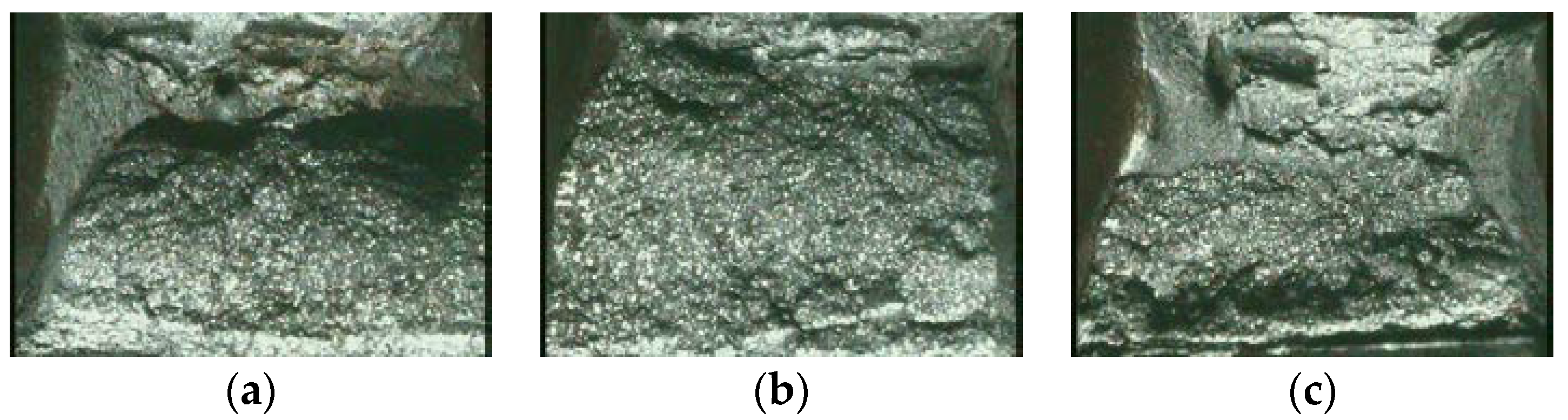
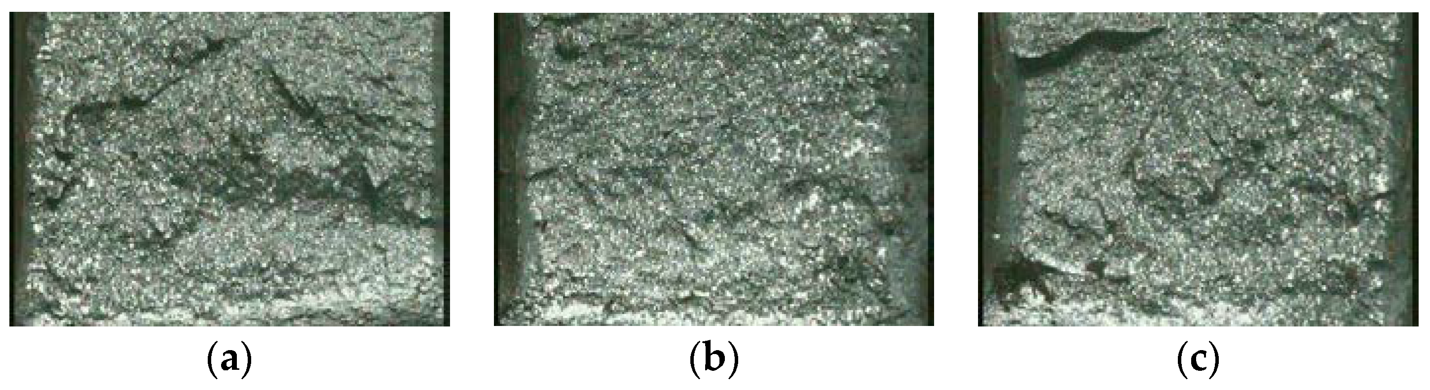
The macroscopic fracture morphologies of impact fracture for different thickness at different temperatures were observed under a 50-fold microscope, and the typical morphology of impact fractures at −20 °C are shown in Figure 1, the typical morphology of impact fractures at −40 °C are shown in Figure 2.
As shown in Figure 1 and Figure 2, the impact section structures of the HAZ for the three-thickness steel plate at −20 °C were much better than these at −40 °C. At −20 °C, the common feature of the three typical impact fractures was that the impact specimen had a large number of deep elongated shear lips near the narrow part of the V-groove area [16], and it appeared farther away from the impact V-groove, with obvious fibrous, fractured areas filled with relatively sharp tear edges, which indicated that the impact toughness of the HAZ is better at −20 °C. For comparison, the ratio of the long shear lip in the fracture of the 25 mm steel plate was relatively low, and the impact absorbed energy was also significantly lower than the other two.
Compared with the above, the three typical impact fractures in Figure 2a–c were relatively flat, with a large number of small facets, radial and herringbone stripes, and there was no obvious tearing edge.
3.2.2. Microscopic Feature
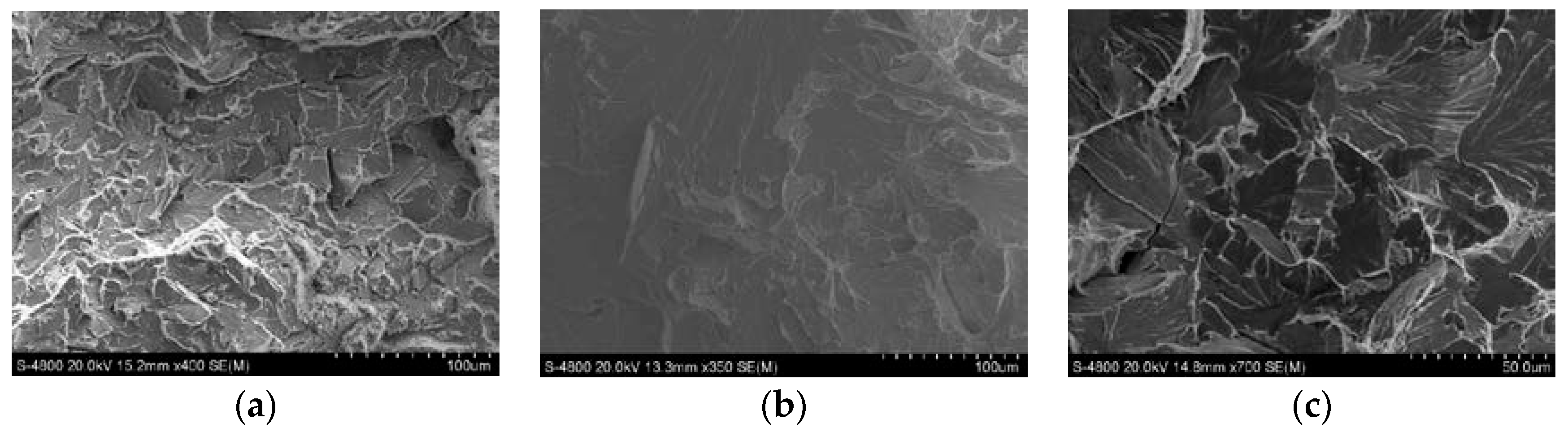
The impact fracture specimen was sampled by wire cut at a distance of 10 mm from the fracture surface. The sample was cleaned with an ultrasonic cleaner, then wiped with alcohol, dried, and finally placed in a scanning electron microscope to observe the microscopic appearance of the fracture. The typical microscopic morphology of impact fractures for different plate thicknesses at −20 °C are shown in Figure 3, and the typical microscopic morphology of impact fractures for different plate thicknesses at −40 °C are shown in Figure 4.
Typical micrographs of impact fractures in the heat affected zone of steel plates thickness 16 mm, 25 mm, and 40 mm at −20 °C are shown in Figure 3a–c, and the impact absorbed values were 197.3 J, 42.5 J, and 197.6 J, respectively. Among them, the fracture micro-morphology shown in Figure 3a was a dense and unequal equiaxed dimple formed by tensile pulling force, and there was a phenomenon of enrichment of small dimples near the large dimple, and it was the typical ductile fractures; as shown in Figure 3b, the microscopic morphology of the fractures was as a fan-shaped cleavage pattern, in which there were distinct torn edges, and there were very few small and shallow dimples in some regions, and there were also solutions in the entire section. Columns are typical quasi-cleavage fractures; the fractures shown in Figure 3c were composed of sheared elongated dimples and partially shallow and small equiaxed dimples, in which elongated dimples had a certain direction. The reason for the above is that the sample was punctured and ruptured under the impact of an impact force and was a typical ductile fracture. For the perspective of the fracture mechanism, the microscopic morphologies of the three types of fractures were consistent with the corresponding impact energy values [16,17,18].
Figure 4a–c show the typical microscopic appearances of impact fractures in the HAZ of steel plate thicknesses of 16 mm, 25 mm and 40 mm at −40 °C, respectively, under the corresponding energy welding conditions. The corresponding impact absorbed values were 49.0 J, 17.4 J and 35.7 J, respectively. Among them, Figure 4a shows that the uneven dimples appeared in the micro-morphology of the fracture surface, and also that there were some smaller cleavage surfaces, and clearer tearing edges, which were typical characters of the quasi-cleavage fracture; Figure 4b shows that the micro-morphology of the fracture was mainly a river pattern. During the process of extending from the cleavage crack outward to the crystal phase, a large number of steps gather and the direction of the river flow were consistent with the direction in which the crack extends outward. The brittle fractures of Figure 4c shows fracture features resembling “fans” at the fractures, which were mainly due to cleavage cracks originating in the crystal near the grain boundary, and the river pattern would be in the form of a fan to extend outwards, and these were the typical quasi-cleavage fracture [16,17,18].
Figure 4a–c show the typical microscopic appearances of impact fractures in the HAZ of steel plate thicknesses of 16 mm, 25 mm and 40 mm at −40 °C, respectively, under the corresponding energy welding conditions. The corresponding impact absorbed values were 49.0 J, 17.4 J and 35.7 J, respectively. Among them, Figure 4a shows that the uneven dimples appeared in the micro-morphology of the fracture surface, and also that there were some smaller cleavage surfaces, and clearer tearing edges, which were typical characters of the quasi-cleavage fracture; Figure 4b shows that the micro-morphology of the fracture was mainly a river pattern. During the process of extending from the cleavage crack outward to the crystal phase, a large number of steps gather and the direction of the river flow were consistent with the direction in which the crack extends outward. The brittle fractures of Figure 4c shows fracture features resembling “fans” at the fractures, which were mainly due to cleavage cracks originating in the crystal near the grain boundary, and the river pattern would be in the form of a fan to extend outwards, and these were the typical quasi-cleavage fracture [16,17,18].
As shown in the experimental results, it can be seen that both the macroscopic appearance and the microscopic appearance of the fracture were matched with the corresponding impact absorbed energy values, and there was no sharp drop in the impact absorbed energy value caused by the steel plate defect, which indicated that the impact energy value could completely represent the impact toughness of the HAZ of the steel plate under the corresponding welding and impact conditions.
4. Discussion
4.1. Influence of Welding Heat Input
For normal conditions, the welding line energy characterizes the heat input per welding area, but for different thickness steel plates, the heat load in the local area does not necessarily increase with the increase of weld heat input, it also depends on the steel plate thickness. For this reason, the welding heat load of three kinds of steel plates had been calculated. The results are shown in Figure 5. From Figure 5, it could be seen that the 25 mm thickness steel plate had the highest heat load, reaching 0.40 kJ/mm2, which would exacerbate the tendency to deteriorate the microstructure of the heat-affected zone, which may be one of the causes for its lower impact toughness. Although the thermal load of the 40 mm thickness steel plate had reached 0.38 kJ/mm2, the impact on the impact test results was relatively small.
At −40 °C, the impact absorbed energy values of the three were greatly reduced, especially for the 40 mm thickness steel plate, and correspondingly, the impact energy value reduced 163.3 J, even lower than the corresponding value of the 25 mm thickness steel plate, which was 32.0 J. The impact energy value of the 16 mm thickness steel plate was 71 J, more than twice that of the other two. The key factor that causes this result was the ductile–brittle transition temperature of the test steel.
The ductile–brittle transition temperature of steel is influenced by factors such as thermal processing [19,20], metallurgical composition [21], and grain boundary precipitation [22]. For this research, the metallographic structure properties and heat load were closely related in the welding process [23]. From Figure 5, it could be seen that the corresponding heat load of the 16 mm thickness steel plate was significantly lower than the other two, and the impact energy value at the −40 °C corresponding to the HAZ was 71 J, which was obviously higher than that of the other two also. It is shown that the welding heat input had a great influence on the ductile–brittle transition temperature of the steel.
In theory, the cooling rate has a greater impact on the microstructure [24,25]. With the increase of the thickness of the steel plate, under the same external cooling conditions, the greater the thickness of the steel plate, the lower the overall cooling rate. Moreover, the heat loads of 25 mm and 40 mm thickness steel plates were all higher than those of 16 mm, so the impact of welding heat input on impact toughness of 25 mm and 40 mm thick steel plates, especially the impact on the ductile–brittle transition temperature, was significantly higher than that of the 16 mm thick steel plates. However, at the same time, at −20 °C, without considering the influence of the ductile–brittle transition temperature of the test steel, the impact toughness of 40 mm thickness steel plate was much higher than that of 25 mm, so the metallographic structures of the three thickness steel plates should be analyzed further.
4.2. Analysis of Metallographic Structures
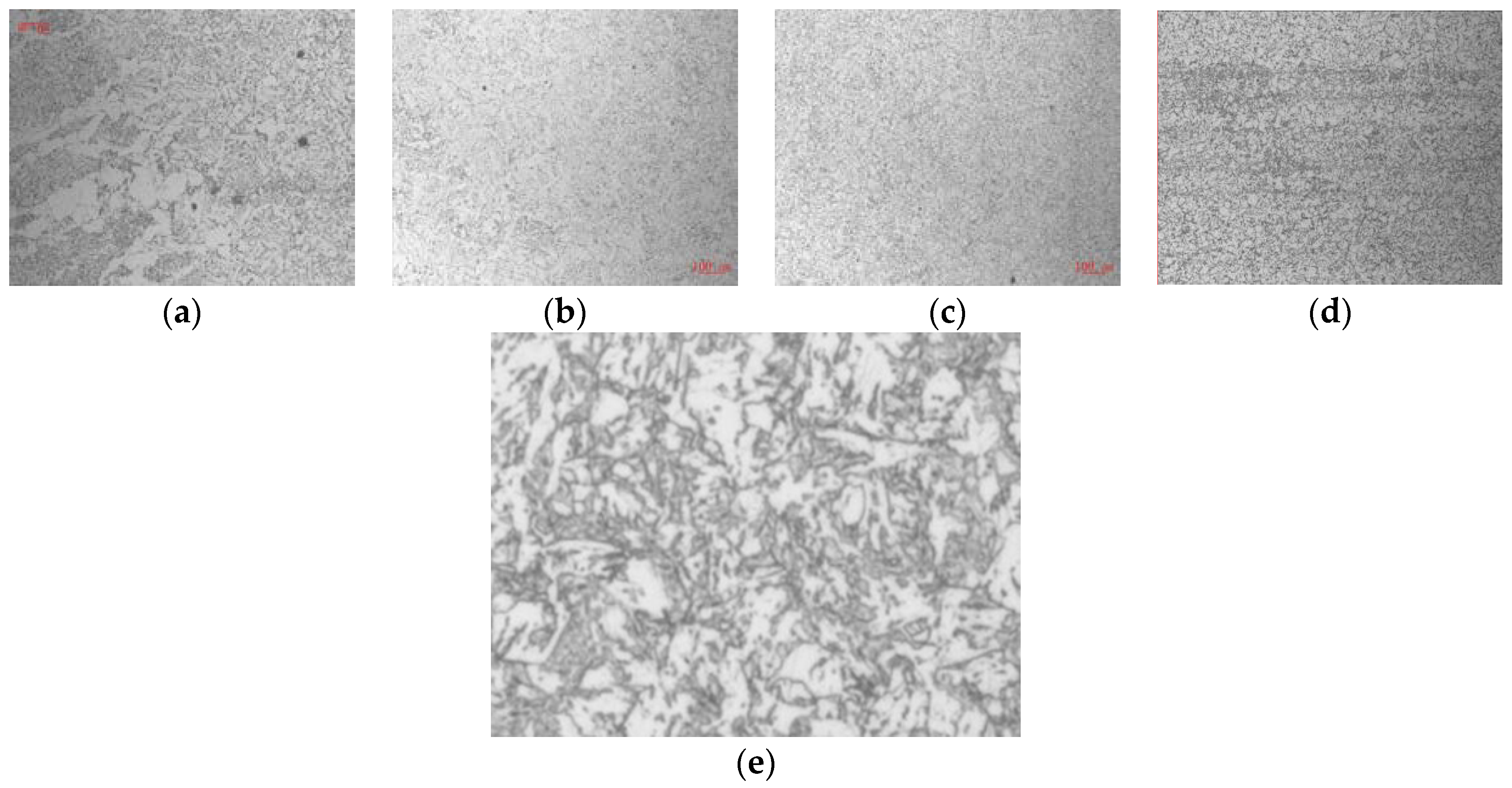
The metallographic structure of 16 mm thickness steel plate with welding heat input 50 kJ/cm under 100-fold field of view are shown in Figure 6a–d, and the higher magnification image of partial area of Figure 6b is shown in Figure 6e. Figure 6a is the welding fusion zone, Figure 6b,c are the welding heat affected zone, and Figure 6d is the metallographic structure of the steel plate.
As shown in Figure 6a, the metallographic structure of the HAZ in the right half of the weld line was a little thicker, which was approximately 100 μm away from the weld line, but with the distance increasing, the structure became finer. Combining with the metallographic structures of the two welding heat affected zones in Figure 6b,c, especially in Figure 6e, it could be found that the overall HAZ structure was relatively uniform, and due to the appearance of a large number of IAF, The austenite grain in the heat-affected zone had been effectively fined. For the entire weld heat affected zone, the nearer to the weld line, the higher the rate of IAF in the metallurgical structure. Under the condition that a large amount of IAF was induced, the heat affected zone was even more fine and uniform than the original plate (as shown in Figure 6d).
The metallographic structure of 25 mm thickness steel plate with welding heat input 100 kJ/cm under 100-fold field of view are shown in Figure 7a–d, and the higher magnification image of partial area of Figure 7b is shown in Figure 7e. Figure 7a is the welding fusion zone, Figure 7b,c are the welding heat affected zone, and Figure 7d is the metallographic structure of the steel plate.
As shown in Figure 7a, the metallographic structure of the right side of the fusion line was significantly coarsened. The metallographic structure of the HAZ showed in Figure 7b was closer to the weld fusion line; it is shown that, the metallographic structure in the lower left area was significantly coarser than that of the upper right area, and the microstructure in the upper right area was the same as the metallographic structure shown in Figure 7c,e than the higher magnification images. This showed that, due to the larger heat load of the 25 mm thickness steel plate, the metallographic structure was obviously coarsened. However, due to the induction of IAF, which had effectively restricted the coarsening of the microstructure, the roughening of the most of the heat-affected zones was not as serious as compared with the steel plate. This is the reason that the impact toughness value of the 25 mm thickness steel plate could reach twice that of the national standard.
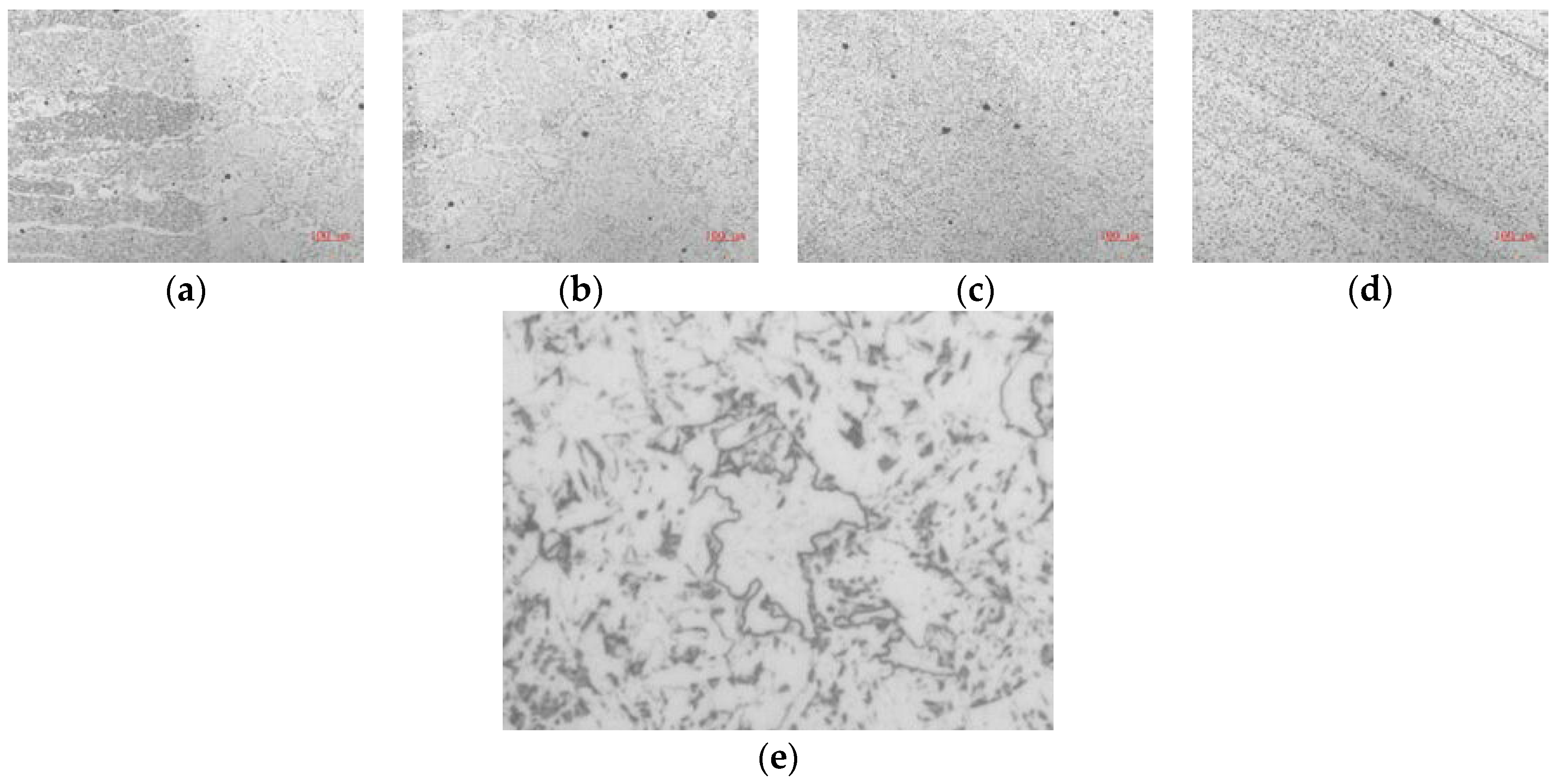
The metallographic structure of 40 mm thickness steel plate with welding heat input 150 kJ/cm under 100-fold field of view are shown in Figure 8a–d, and the higher magnification image of partial area of Figure 8b is shown in Figure 8e. Figure 8a is the welding fusion zone, Figure 8b,c are the welding heat affected zone, and Figure 8d is the metallographic structure of the steel plate.
At −20 °C, the HAZ impact toughness of 40 mm thickness steel plate was similar to 16 mm thickness steel plate, as shown in Figure 8a–d, the metallographic structure was also the same as the corresponding area of the 16 mm thickness steel plate. With a large amount of IAF inducing, the metallographic structure of HAZ was not only no coarser, but also even more uniform and finer than the steel plate.
For the above analysis, it could be seen that the welding heat load of a 25 mm thickness steel plate was not much different from 40 mm thickness steel plate, but the impact toughness value was significantly lower than the 40 mm thickness steel plate. As shown in Figure 7d and Figure 8d, the microstructures of 25 mm thickness steel plate were significantly thicker than that of the 40 mm thickness steel plate, and the corresponding welded heat affected zone also showed the same phenomenon. Due to the coarseness of the original structure of the steel plate, the microstructure of the welding heat affected zone is severely roughened, which indicates that the resistance of the coarse structure to the weld line energy is far worse than that of the fine structure. This also leads to the reduction of the impact toughness of the welded heat affected zone of the 25 mm thickness steel plate. The above analysis indicates that the TMCP process used to roll the 25 mm thick steel plates in actual production needs further optimization.
At −40 °C, the metallographic structure of the weld heat affected zone did not change, but the corresponding impact toughness value of the 40 mm thickness steel plate decreased drastically; that indicated that the ductile brittle transition temperature of the test steel was not directly related to the thickness of the metallographic structure. Shen Dongdong et al [26] have also obtained similar results.
Through the above metallographic analysis, it could be found that the metallographic structure of the HAZ of the 16 mm and 40 mm thickness steel plates was even finer than that of the original steel plate. The HAZ metallographic structure of the 25 mm thickness steel plate was coarser than the original steel plate. That was attributed to the induction of the amount of IAF in the HAZ. Therefore, it is necessary to do further analysis about the inclusions which induced the IAF.
4.3. Analysis of Inclusions
For oxide metallurgical steels, the inclusions could pin the austenite grains to prevent growing, and could also induce the IAF in the austenite grains to make the grain finer. Therefore, for the HAZ with the three different thicknesses steel plates, the number of micro-inclusions had been statistically graded in this study [27,28], and the results are shown in Table 4.
As shown in Table 4, the inclusion size of the HAZ was mainly in the range of 0–5 μm. These types of oxides could be the nuclear core for IAF inducing and play the pinning effect to restrict austenite grains growing. In comparison, for the range of 0–5 μm, the maximum number of inclusions in the heat affected zone of the 25 mm thick steel plate was the largest, but the IAF rate of the 25 mm thickness steel plate was relatively low; this may be due to the relative thicker metallographic structure for the 25 mm thickness of the original steel plate.
For further research, the oxides size for the shipbuilding steel with Mg and normal shipbuilding steel without Mg had been counted by the Aspex, the results are shown in Table 5.
As the results show in Table 5, for the shipbuilding steel in this research, the number of the microscopic inclusions per unit area was increased, and the total area of microscopic inclusions was decreased, as compared with the normal shipbuilding steel without Mg. It showed that, with Mg added, the inclusions had been refined effectively.
The oxide metallurgy effect for the different size inclusions is closely related to the metallographic structure of the steel plate. From the previous studies of the authors, in the as-cast condition, the IAF had been induced by the inclusions mainly with the size of 10 μm, and inclusions in the range of 15–20 μm could also be used as the core to induce the IAF, but for the rolled plate with smaller grain size, the IAF could only be induced by the smaller inclusions.
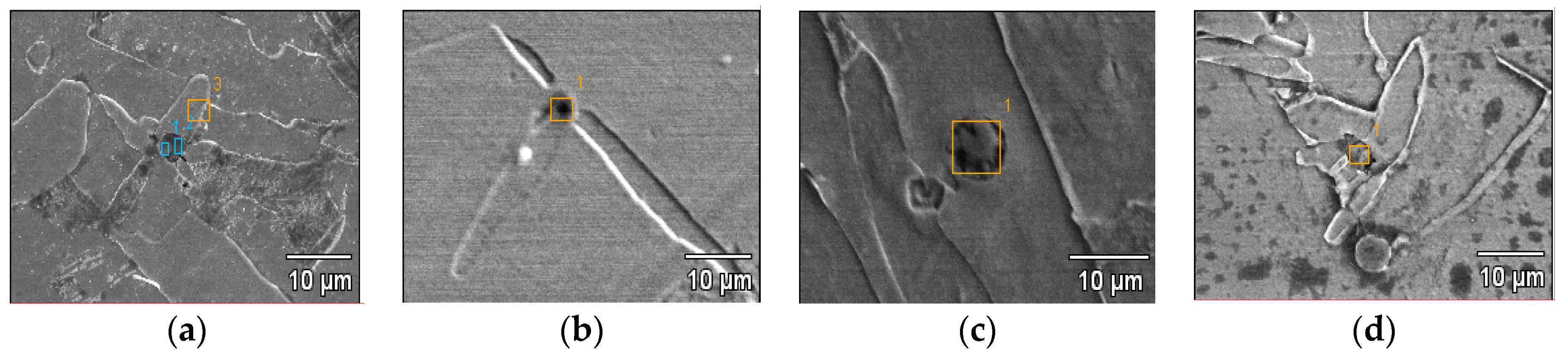
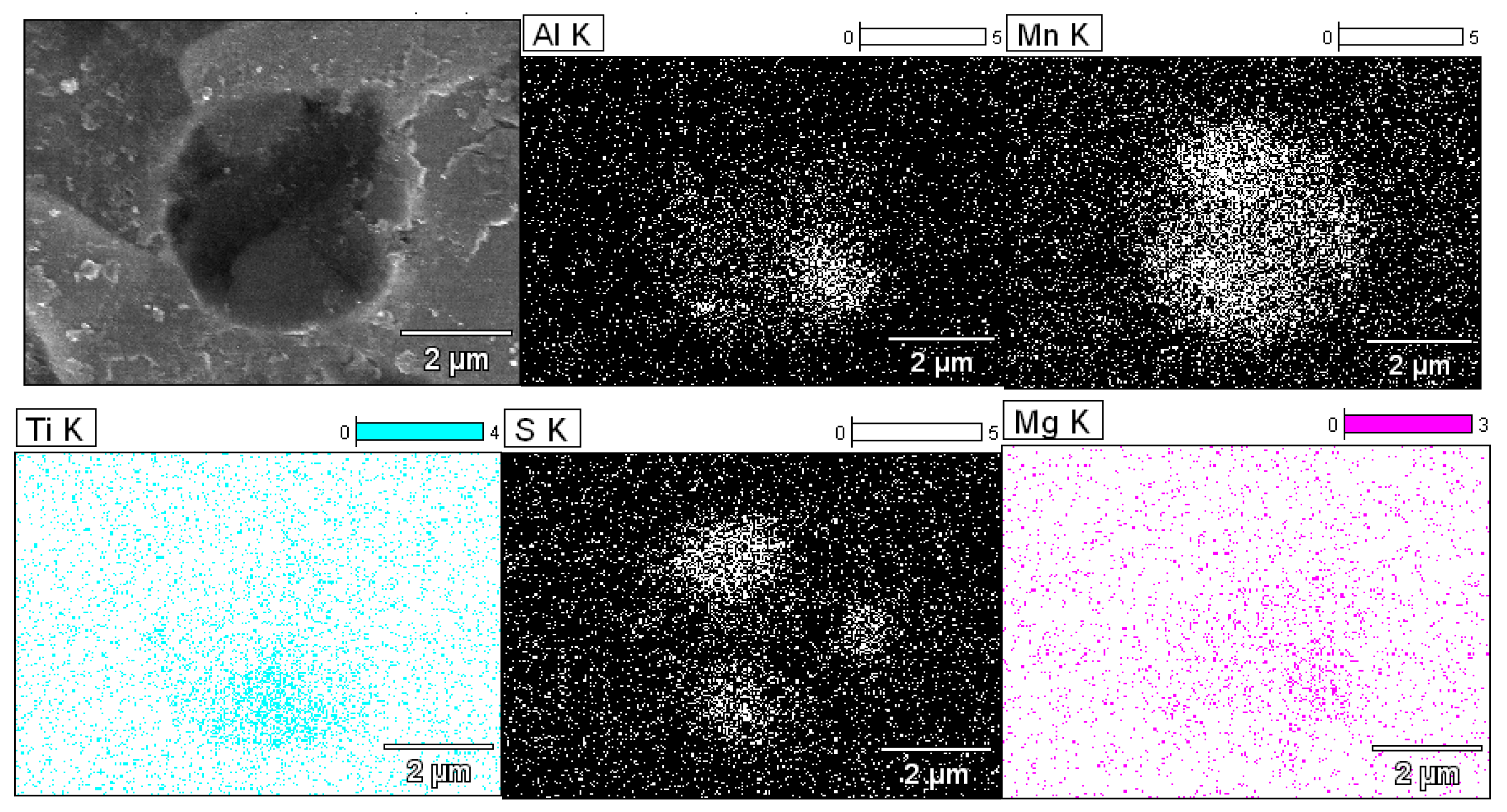
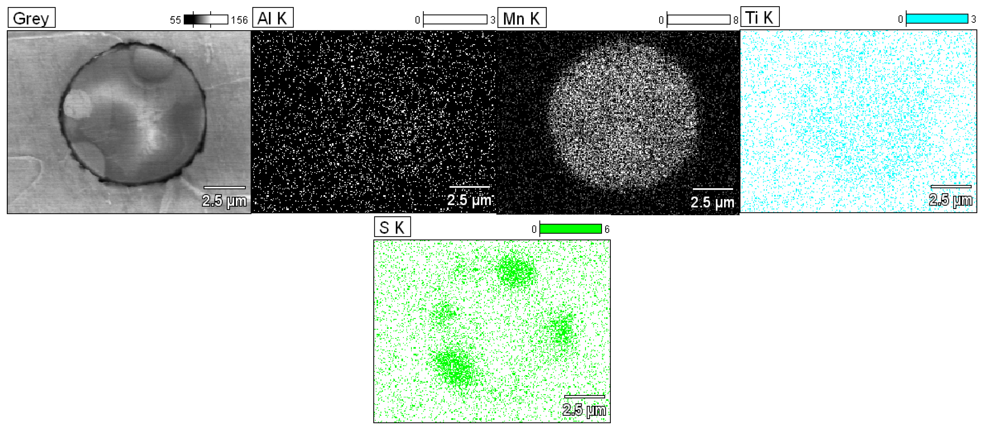
The typical morphologies of IAF and its inducing cores (inclusions) were shown in Figure 9. It is shown that, these inclusions were substantially spherical and their size were mostly about 3 μm. In order to further analyze the composition of inclusions, in this study, scanning electron microscopy and energy spectroscopy were used to perform surface scan analysis of inclusions. The representative inclusion surface scans are shown in Figure 10 and Figure 11, respectively. In this study, the five elements of Mg, Al, Mn, Ti and S that have an important influence on the induction of IAF were mainly investigated.
Figure 10 is a typical surface scan of Mg-containing inclusions that induced IAF. As shown in Figure 10, the size of the inclusion was 3–4 μm, corresponding to the inclusion in Figure 9b. For the five elements examined, the Mg elements were basically diffusely distributed; the Mn element was substantially full of inclusions, but was more concentrated at three positions; the Al and Ti elements were relatively more concentrated in the lower half; the S elements were concentrated in the inclusions at three points on the periphery.
As shown in Figure 9b, the inclusions induced a total of three acicular ferrite branches, and the three branches correspond to the three points in S. Under normal conditions, S existed in the form of MnS, and the concentration of S and Mn causes the decrease of the Mn content in the surrounding area, which in turn induces acicular ferrite.
Figure 11 is a typical surface scan of Mg-free inclusion that induced IAF. As shown in Figure 11, the size of the inclusion was about 7 μm, corresponding to the inclusion in Figure 9c. Among the elements examined, the Mn element was substantially filled with the entire inclusion; Al and Ti elements were basically dispersed; S element was concentrated on the four points of the periphery of the inclusion and appeared in the other two areas on the periphery of the inclusion.
5. Conclusions
- (1)
- The HAZ of three kinds of thickness plates induced much IAF; with Mg addition, the inclusion dimension had been reduced effectively, and the IAF induced ability of the inclusions had also been improved. If the original metallographic microstructure of steel was coarse, the pinning effect of the inclusions would be reduced significantly, and the microstructure of HAZ would be coarsened and the impact toughness of HAZ would be decreased, so there is a certain matching relationship between the metallographic microstructure and the inclusion dimension.
- (2)
- Mg is not the primary cause of the IAF inducing, but Mg can effectively reduce the size of inclusions, and thus increase the inclusion ability of IAF inducing.
- (3)
- The difference of HAZ impact toughness with different welding heat input and different impact temperature is significant; considering the influence of welding heat input and metallographic microstructure on the impact toughness of HAZ, the welding heat load had a far greater effect than the metallographic microstructure on the ductile–brittle transition temperature.
Author Contributions
Conceptualization, L.-g.S.; Funding acquisition, L.-g.Z. and L.-g.S.; Software, Y.-s.L.; Supervision, Y.-g.L. and L.-g.S.; Writing—review & editing, H.-r.L.
Funding
This research was funded by National Natural Science Foundation of China, grant number 51474089, and by Natural Science Foundation of Hebei Province, grant number E2017209194.
Acknowledgments
We would like to extend my sincere gratitude to Professor Wang Shuoming and Professor Liu Zengxun, for their instructive advice and useful suggestions on the thesis. We also thanks the engineers in Handan steel company, they provided a lot for the industrial experiment.
Conflicts of Interest
The authors declare no conflict of interest.
References
- Takamura, J.; Mizoguchi, S. Role of oxides in steels perform ances metallurgy of oxides in steels. In Proceedings of the ISIJ Sixth International Iron and Steel Congress, Nagoya, Japan, 21–26 October 1990; pp. 591–597. [Google Scholar]
- Mizoguchi, S.; Takamura, J. Control of oxides as inoculants metallurgy of oxides in steels. In Proceedings of the ISIJ Sixth International Iron and Steel Congress, Nagoya, Japan, 21–26 October 1990; pp. 598–604. [Google Scholar]
- Hitoshi, H. Effect of Ti and alloying elements on microstructure and toughness of simulated HAZ of 780 MPa class steels. Tetsu-to-Hagane 2004, 90, 271–277. [Google Scholar]
- Shu, W.; Wang, X.; Li, S.; He, X. Nucleation and growth of intragranular acicular ferrite and its effect on grain refinement of the heat-affected-zone. Acta Metall. Sin. 2011, 47, 435–441. [Google Scholar]
- Hong, S.G.; Kang, K.J.; Park, C.G. Strain-induced precipitation of NbC in Nb and Nb-Ti microalloyed HSLA steels. Scr. Mater. 2002, 46, 163–168. [Google Scholar] [CrossRef]
- Vega, M.I.; Medina, S.F.; Quispe, A.; Gomez, M.; Gomez, P.P. Influence of TiN particle precipitation state on static recrystallisation in structural steels. ISIJ Int. 2005, 45, 1878–1886. [Google Scholar] [CrossRef]
- Kanazawa, S.; Nakashima, A.; Okamoto, K.; Kanaya, K. Improved toughness of weld fussion zone by fine TiN particles and development of a steel for large heat input welding. Tetsu-to-Hagane 1975, 61, 2589–2603. [Google Scholar] [CrossRef]
- Kasamatsu, Y. Effect of titanium and nitrogen on toughness of heat-affected zone of steel plate with tensile strength of 50 kg/mm2 in high heat input welding. Tetsu-to-Hagane 1979, 65, 1232–1241. [Google Scholar] [CrossRef]
- Song, M.; Song, B.; Hu, C.; Xin, W.B.; Song, G.Y. Effect of Ti--Mg complex deoxidation on the microstructure and impact properties of HAZ in steel. Chin. J. Eng. 2015, 37, 883–888. [Google Scholar]
- Zhu, K.; Yang, Z. Effect of Mg addition on the ferrite grain boundaries misorientation in HAZ of low carbon steel. J. Mater. Sci. Technol. 2011, 27, 252–256. [Google Scholar] [CrossRef]
- Sun, Z.; Huang, J.; Zhang, H.; Zhao, X.; Li, Q. Microstructures and mechanical properties of joints of mi-croalloyed EH40 ship steel with high heat-input welding. Trans. China Weld. Inst. 2008, 29, 42–43. [Google Scholar]
- Sohn, S.S.; Hong, S.; Lee, J.; Suh, B.-C.; Kim, S.-K.; Lee, B.-J.; Kim, N.J.; Lee, S. Effects of Mn and Al contents on cryogenic-temperature tensile and Charpy impact properties in four austenitic high-Mn steels. Acta Mater. 2015, 100, 39–52. [Google Scholar] [CrossRef]
- Hwang, B.; Lee, C.G. Influence of thermomechanical processing and heat treatments on tensile and Charpy impact properties of B and Cu bearing high-strength low-alloy steels. Mater. Sci. Eng. A 2010, 527, 4341–4346. [Google Scholar] [CrossRef]
- You, Y.; Wang, X.; Shang, C. Influence of austenitizing temperature on the microstructure and impact toughness of a high strength low alloy HLSA100 steel. Acta Metall. Sin. 2012, 48, 1290–1298. [Google Scholar] [CrossRef]
- Sung, H.K.; Shin, S.Y.; Cha, W.; Oh, K.; Lee, S.; Kim, N.J. Effects of acicular ferrite on charpy impact properties in heat affected zones of oxide-containing API X80 linepipe steels. Mater. Sci. Eng. A 2011, 528, 3350–3357. [Google Scholar] [CrossRef]
- Tao, P.; Yu, H.; Fan, Y.; Fu, Y. Effects of cooling method after intercritical heat treatment on microstructural characteristics and mechanical properties of as-cast high-strength low-alloy steel. Mater. Des. 2014, 54, 914–923. [Google Scholar] [CrossRef]
- Li, L.; Cao, F.; Wang, Y.; Zhang, X.; Lu, C. Analysis on low temperature impact toughness and fracture morphologies of X90 pipeline steel. Heat Treat. Met. 2015, 40, 190–193. [Google Scholar]
- Luo, K.Y.; Wang, C.Y.; Sun, G.F.; Cui, C.Y.; Sheng, J.; Lu, J.Z. Investigation and microstructural analyses of massive LSP impacts with coverage area on crack initiation location and tensile properties of AM50 magnesium alloy. Mater. Sci. Eng. A 2016, 650, 110–118. [Google Scholar] [CrossRef]
- Chatterjee, A.; Chakrabarti, D.; Moitra, A.; Mitra, R.; Bhaduri, A.K. Effect of deformation temperature on the ductile–brittle transition behavior of a modified 9Cr-1Mo steel. Mater. Sci. Eng. A 2015, 630, 58–70. [Google Scholar] [CrossRef]
- Bai, X.; Wu, S.; Liaw, P.K. Influence of thermo-mechanical embrittlement processing on microstructure and mechanical behavior of a pressure vessel steel. Mater. Des. 2016, 89, 759–769. [Google Scholar] [CrossRef]
- Nazari, A.; Milani, A.A.; Khalaj, G. Modeling ductile to brittle transition temperature of functionally graded steels by ANFIS. Appl. Math. Model. 2012, 36, 3903–3915. [Google Scholar] [CrossRef]
- Chen, X.M.; Song, S.H.; Weng, L.Q.; Liu, S.J.; Wang, K. Relation of ductile-to-brittle transition temperature to phosphorus grain boundary segregation for a Ti-stabilized interstitial free steel. Mater. Sci. Eng. A 2011, 528, 8299–8304. [Google Scholar] [CrossRef]
- Kumar, S.; Nath, S.K. Effect of heat input on impact toughness in transition temperatureregion of weld CGHAZ of a HY 85 steel. J. Mater. Proc. Technol. 2016, 236, 216–224. [Google Scholar] [CrossRef]
- Goto, H.; Miyazawa, K.; Yamaguchi, K.; Ogibayashi, S.; Tanaka, K. Effect of cooling rate on oxide precipitation during solidification of low carbon steels. ISIJ Int. 1994, 34, 414–419. [Google Scholar] [CrossRef]
- Goto, H.; Miyazawa, K.; Tanaka, K. Effect of oxygen Content on size distribution of oxides in steel. ISIJ Int. 1995, 35, 286–291. [Google Scholar] [CrossRef]
- Shen, D.; Yuan, Z. Factors influencing the DBTT of 2.25CrMo steel. J. Wuhan Univ. Sci. Technol. 2011, 34, 410–413. [Google Scholar]
- Yang, L.; Liu, J.; Bao, Y. Researches on X70 cleanliness in refine and continuous casting process. J. Univ. Sci. Technol. Beijing 2007, 29, 97–100. [Google Scholar]
- Li, C.; Bao, Y.; Liu, J. Investigation of reasonable cleanliness for high-grade linepipe steel scale production. J. Univ. Sci. Technol. Beijing 2007, 29, 10–13. [Google Scholar]
Figure 1.
Macroscopic fracture (−20 °C): (a), impact fracture of 16 mm thickness plate; (b), impact fracture of 25 mm thickness plate; (c), impact fracture of 40 mm thickness plate.
Figure 1.
Macroscopic fracture (−20 °C): (a), impact fracture of 16 mm thickness plate; (b), impact fracture of 25 mm thickness plate; (c), impact fracture of 40 mm thickness plate.

Figure 2.
Macroscopic fracture (−40 °C): (a), impact fracture of 16 mm thickness plate; (b), impact fracture of 25 mm thickness plate; (c), impact fracture of 40 mm thickness plate.
Figure 2.
Macroscopic fracture (−40 °C): (a), impact fracture of 16 mm thickness plate; (b), impact fracture of 25 mm thickness plate; (c), impact fracture of 40 mm thickness plate.

Figure 3.
Sample of micro-fracture (−20 °C): (a), impact fracture of 16 mm thickness plate; (b), impact fracture of 25 mm thickness plate; (c), impact fracture of 40 mm thickness plate.
Figure 3.
Sample of micro-fracture (−20 °C): (a), impact fracture of 16 mm thickness plate; (b), impact fracture of 25 mm thickness plate; (c), impact fracture of 40 mm thickness plate.
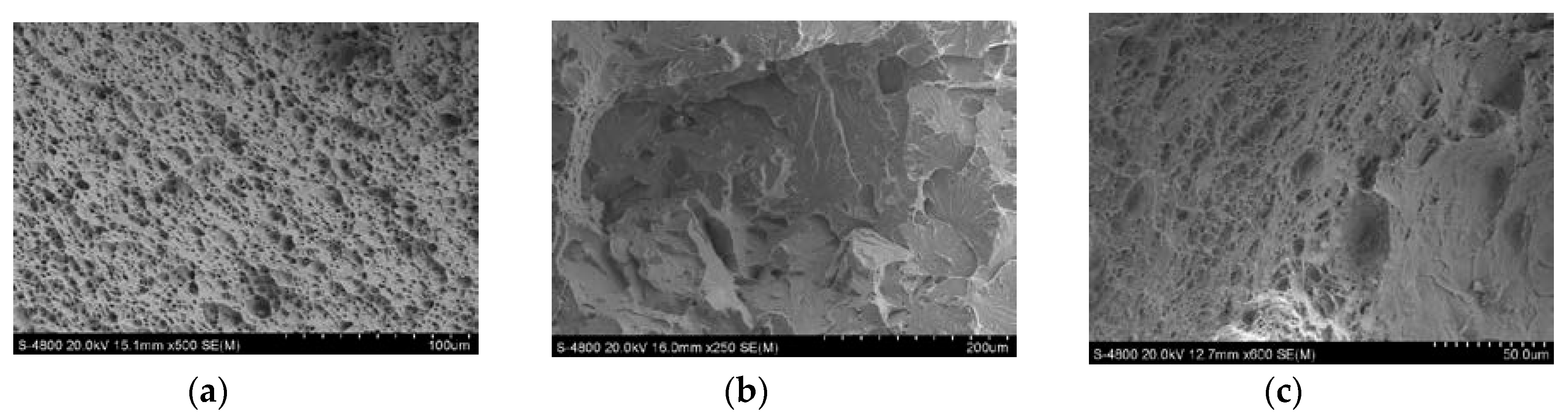
Figure 4.
Sample of micro-fracture (−40 °C): (a), impact fracture of 16 mm thickness plate; (b), impact fracture of 25 mm thickness plate; (c), impact fracture of 40 mm thickness plate.
Figure 4.
Sample of micro-fracture (−40 °C): (a), impact fracture of 16 mm thickness plate; (b), impact fracture of 25 mm thickness plate; (c), impact fracture of 40 mm thickness plate.

Figure 5.
Welding heat load.
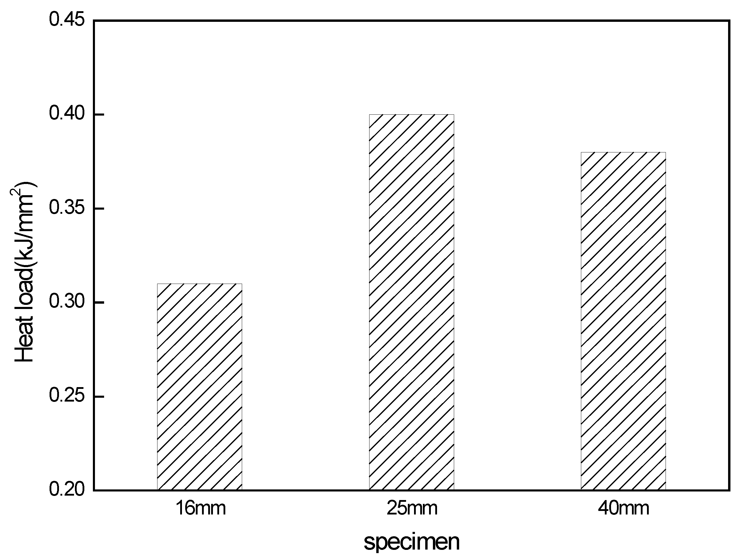
Figure 6.
Metallographic structure of HAZ for 16 mm thickness: (a), the metallographic structure of welding fusion zone; (b,c), the metallographic structure of welding heat affected zone; (d), the metallographic structure of the steel plate; (e), the higher magnification image of partial area of Figure 6b.

Figure 7.
Metallographic structure of HAZ for 25 mm thickness: (a), the metallographic structure of welding fusion zone; (b,c), the metallographic structure of welding heat affected zone; (d), the metallographic structure of the steel plate; (e), the higher magnification image of partial area of Figure 7b.

Figure 8.
Metallographic structure of HAZ for 40 mm thickness: (a), the metallographic structure of welding fusion zone; (b,c), the metallographic structure of welding heat affected zone; (d), the metallographic structure of the steel plate; (e), the higher magnification image of partial area of Figure 8b.


Figure 9.
Typical characters of the inclusions which induced intragranular acicular ferrite (IAF). (a), inclusion size is about 2.5 μm; (b), inclusion size is about 3.0 μm; (c), inclusion size is about 7.0 μm; (d), inclusion size is about 3.3 μm.
Figure 9.
Typical characters of the inclusions which induced intragranular acicular ferrite (IAF). (a), inclusion size is about 2.5 μm; (b), inclusion size is about 3.0 μm; (c), inclusion size is about 7.0 μm; (d), inclusion size is about 3.3 μm.

Figure 10.
Surface scanning analysis of inclusions that contain Mg.

Figure 11.
Surface scanning analysis of inclusions that free from Mg.


Table 1.
The chemical composition of the steel trial (mass%).
| Composition | C | Si | Mn | S | P | Al | Ti | Mo | V | Nb | Mg |
|---|---|---|---|---|---|---|---|---|---|---|---|
| content | 0.08 | 0.20 | 1.40 | 0.005 | 0.015 | 0.01 | 0.015 | 0.07 | 0.04 | 0.04 | 0.005 |
Table 2.
Welding parameters.
| Thickness (mm) | Input Line Energy (KJ/cm) | Welding Speed (m/h) | Welding Wire Diameter (mm) | Welding Wire Kinds | Fore Wire | Hind Wire | ||
|---|---|---|---|---|---|---|---|---|
| Current | Voltage | Current | Voltage | |||||
| (A) | (V) | (A) | (V) | |||||
| 16 | 50 | 19.6 | 4.0 | 10Mn2 | 780 | 35 | ||
| 25 | 100 | 24 | 5.0 + 5.0 | 10Mn2 + SJ501 | 1000 | 41 | 700 | 37 |
| 40 | 150 | 22.7 | 5.0 + 5.0 | 10Mn2 + SJ501 | 1200 | 44 | 1000 | 42 |
Table 3.
Impact results.
| Thickness/mm | Input Line Energy/kJ/cm | Impact Temperature/°C | Impact Absorbed Energy/J | Averaged Value/J | ||
|---|---|---|---|---|---|---|
| 16 | 50 | −20 | 197.3 | 166.7 | 172.0 | 178.7 |
| −40 | 89.6 | 49.0 | 74.3 | 71.0 | ||
| 25 | 100 | −20 | 42.5 | 91.4 | 38.6 | 57.5 |
| −40 | 51.8 | 30.2 | 17.4 | 33.1 | ||
| 40 | 150 | −20 | 198.9 | 189.5 | 197.6 | 195.3 |
| −40 | 32.9 | 35.7 | 27.5 | 32.0 | ||
Table 4.
Statistical result of micro-inclusions in different HAZ.
| Thickness of Steel Plate | 0–5 μm | 5–10 μm | 10–15 μm | 15–20 μm |
|---|---|---|---|---|
| 16 mm | 83 | 14 | 16 | 14 |
| 25 mm | 100 | 20 | 8 | 2 |
| 40 mm | 67 | 26 | 6 | 10 |
Table 5.
Partial test results of automatic scanning system for Micro-inclusions.
| Total Scan Area S1 (mm2) | Number of Microscopic Inclusions | Number of Microscopic Inclusions per Unit Area (/mm2) | Total Area of Microscopic Inclusions S2 (mm2) | S2/S1 (%) | |
|---|---|---|---|---|---|
| Normal (without Mg) | 35.4 | 2042 | 57.7 | 0.023 | 0.065 |
| Experiment (with Mg) | 30.0 | 2211 | 73.7 | 0.017 | 0.057 |
© 2018 by the authors. Licensee MDPI, Basel, Switzerland. This article is an open access article distributed under the terms and conditions of the Creative Commons Attribution (CC BY) license (http://creativecommons.org/licenses/by/4.0/).
Share and Cite
MDPI and ACS Style
Li, H.-r.; Sun, L.-g.; Zhu, L.-g.; Liu, Y.-s.; Li, Y.-g. Research on Influential Mechanism of HAZ Impact Toughness for Shipbuilding Steel with Mg Addition. Metals 2018, 8, 584. https://doi.org/10.3390/met8080584
AMA Style
Li H-r, Sun L-g, Zhu L-g, Liu Y-s, Li Y-g. Research on Influential Mechanism of HAZ Impact Toughness for Shipbuilding Steel with Mg Addition. Metals. 2018; 8(8):584. https://doi.org/10.3390/met8080584
Chicago/Turabian StyleLi, Hui-rong, Li-gen Sun, Li-guang Zhu, Yun-song Liu, and Yun-gang Li. 2018. "Research on Influential Mechanism of HAZ Impact Toughness for Shipbuilding Steel with Mg Addition" Metals 8, no. 8: 584. https://doi.org/10.3390/met8080584
Note that from the first issue of 2016, this journal uses article numbers instead of page numbers. See further details here.