Article

Crack Propagation Mechanisms for Creep Fatigue: A Consolidated Explanation of Fundamental Behaviours from Initiation to Failure

Department of Mechanical Engineering, University of Canterbury, Christchurch 8041, New Zealand
*
Author to whom correspondence should be addressed.
Metals 2018, 8(8), 623; https://doi.org/10.3390/met8080623
Submission received: 10 July 2018 / Revised: 1 August 2018 / Accepted: 2 August 2018 / Published: 8 August 2018
(This article belongs to the Special Issue Failure Mechanisms in Alloys)

Abstract

:
Background—Creep-fatigue damage is generally identified as the combined effect of fatigue and creep. This behaviour is macroscopically described by crack growth, wherein fatigue and creep follow different principles. Need—Although the literature contains many studies that explore the crack-growth path, there is a lack of clear models to link these disparate findings and to explain the possible mechanisms at a grain-based level for crack growth from crack initiation, through the steady stage (this is particularly challenging), ending in structural failure. Method—Finite element (FE) methods were used to provide a quantitative validation of the grain-size effect and the failure principles for fatigue and creep. Thereafter, a microstructural conceptual framework for the three stages of crack growth was developed by integrating existing crack-growth microstructural observations for fatigue and creep. Specifically, the crack propagation is based on existing mechanisms of plastic blunting and diffusion creep. Results—Fatigue and creep effects are treated separately due to their different damage principles. The possible grain-boundary behaviours, such as the mismatch behaviour at grain boundary due to creep deformation, are included. The framework illustrates the possible situations for crack propagation at a grain-based level, particularly the situation in which the crack encounters the grain boundary. Originality—The framework is consistent with the various creep and fatigue microstructure observations in the literature, but goes further by integrating these together into a logically consistent framework that describes the overall failure process at the microstructural level.

1. Introduction

The process of fatigue failure is physically and macroscopically described by crack-growth behaviour. The situation is complicated when creep is also present, because this provides an additional mechanism for plastic deformation and crack growth.
In the case of creep-fatigue, an engineering structure fails when the crack length achieves a critical value. The total damage is the accumulated effect of cycle count, temperature, and period (frequency).
Some of the ways this has been modelled is to prove a mathematical representation of the various components of facture mechanics [1,2,3] or to apply curve fitting [4,5,6]. However, this is not the present topic. Here we are more interested in the progression of crack growth at the microstructural level [7,8,9,10], specifically the way the crack navigates through the grains and along grain boundaries under the combined effects of cyclic loading and creep. Existing works do not provide an integrative treatment of this process.
This paper develops a microstructural theory for crack growth. It does so by adapting existing mechanisms of plastic blunting and diffusion creep into an integrative conceptual framework. This provides a logically consistent framework that describes the creep-fatigue failure in terms of microstructural damage.

2. Background Literature

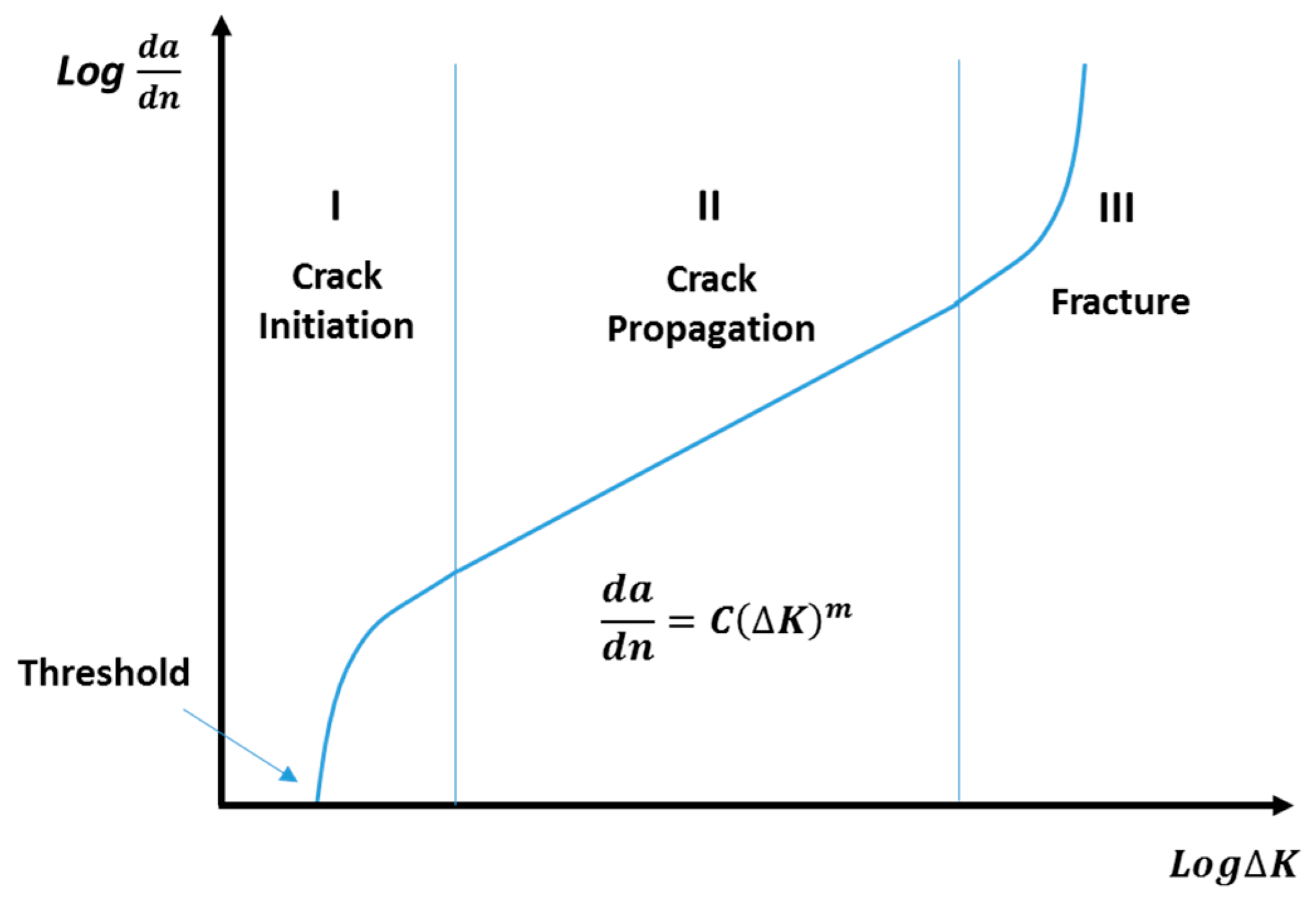
2.1. Phases of Crack Growth

It is generally accepted that the process of crack growth under cyclic loading is divided into three phases (Figure 1) [8]: crack initiation, crack propagation, and structural fracture. Specifically, the first stage presents a threshold, below which there is no crack growth. The second stage shows a relatively steady state, in which the crack growth rate increases steadily with the increasing number of cycles (this is always described by Paris’ Law [11]). The final stage represents an unstable situation, where the engineering structure fails within a small number of cycles.

2.2. Established Principles in the Literature

Crack growth caused by fatigue effect is attributed to plastic deformation at a crack-tip plastic zone, wherein the plastic deformation occurs via dislocations [7]. Ordinarily there is a preferred plane, and in that plane there are specific directions along which dislocation motion occurs; the slip plane. The axial (tension or compression) loading is decomposed into a normal stress, which is perpendicular to the slip plane, and a shear stress, which is parallel to the slip plane. This shear stress then results in the movements along the slip plane. This implies that shear stress contributes to plastic dislocation, and then results in crack growth. In this case, the axial loading is transformed into the shear stress to produce fatigue propagation.
The simplest form of dislocation is edge dislocation, see Figure 2, which represents a simplistic grain unit. Specifically, the dislocation starts from the extra half-plane of atoms (plane I), which is identified as a defect. When a shear stress is applied, and its magnitude is sufficient, the bond between atom A and atom B is cut. Then, the bottom of all planes move to the right, and atom B is bonded with its neighbouring atom (atom C). In this case, a new half-plane of atoms (plane II) is generated. Under the shear stress, this irreversible process is successively and repeatedly presented, with the final result being the creation of a step at the edge of this unit. The process is irreversible because the other atoms in the grain also move into new positions (not shown in the figure) due to other disturbances, hence the atoms do not spontaneously revert to their original positions (plastic deformation). Hence, the dislocation is an enduring feature of the grain. It can, however, be sent in a new direction should the orientation of the shear stress change, as occurs in reversed loading. By this means, the plastic deformation is produced due to the motion of numbers of dislocations. In addition, there may be atomic displacement perpendicular to the plane, hence causing a screw dislocation. In practical situations, the behaviours of edge and screw dislocations are mixed, and both contribute to the overall plastic deformation of the grain and ultimately of the macroscopic deformation of the part.
As mentioned above, the half-plane of atoms is regarded as the source of dislocation. The edge of this half plane is terminated within a grain; hence, a large number of dislocations are piled up, and then plastic deformation arises for the grain as a whole. This implies that the cracks caused by fatigue are initiated within the grains and then are propagated through the grains, causing the observed transgranular fracture phenomenon.
However, the creep mechanism gives a different crack-growth behaviour; crack growth along the grain boundary. In general, crack growth caused by creep is attributed to diffusion behaviour, which is presented as the movements of vacancies [12,13]. Under the creep situation, a constant applied loading leads to stress concentration at the triple points which are formed by the three adjacent grains (Figure 3). Normally, diffusion is a behaviour of atomic shifts from an area with high stress concentration to an area with low stress concentration. In this case, the atomic movements due to the diffusion mechanism results in the convergence of vacancies at the triple points, which then segregate the triple grain boundaries.
By this means, the micro-crack is initiated at the grain boundary. After the process of micro-crack initiation, the localised stress is highly concentrated at the crack tip, which then recruits more vacancies from the bulk of the grain, and these are diffused to the crack tip along the grain boundary. This leads to further propagation of the creep crack along the grain boundary. High temperature provides more favourable conditions for diffusion behaviour, hence advances the creep crack along grain boundaries. Thus, creep failure is strongly temperature dependent.
Overall, crack-growth behaviours of fatigue and creep follow different principles; specifically, fatigue effect occurs via cracks through the grains, while the creep effect involves fracture along the grain boundary.
Significant research effort has been exerted to explore the crack-growth path, through performing fatigue tests and observing the fracture surfaces (fractography). These research efforts mainly focus on the specific features of crack growth for fatigue or creep, such as the creep damage caused by triple points [14,15,16] and grain-boundary effects for fatigue-crack growth [17,18].
In summary, the literature proposes multiple mechanisms at the microstructural level to describe the crack-growth process.
Stage I: Crack initiation
(a)
Dislocation behaviour [19] is a key mechanism at crack initiation. This effect is widely accepted [19]. This effect causes the slip planes to extrude or intrude, which results in stress concentration at the surface and then leads to crack nucleation.
(b)
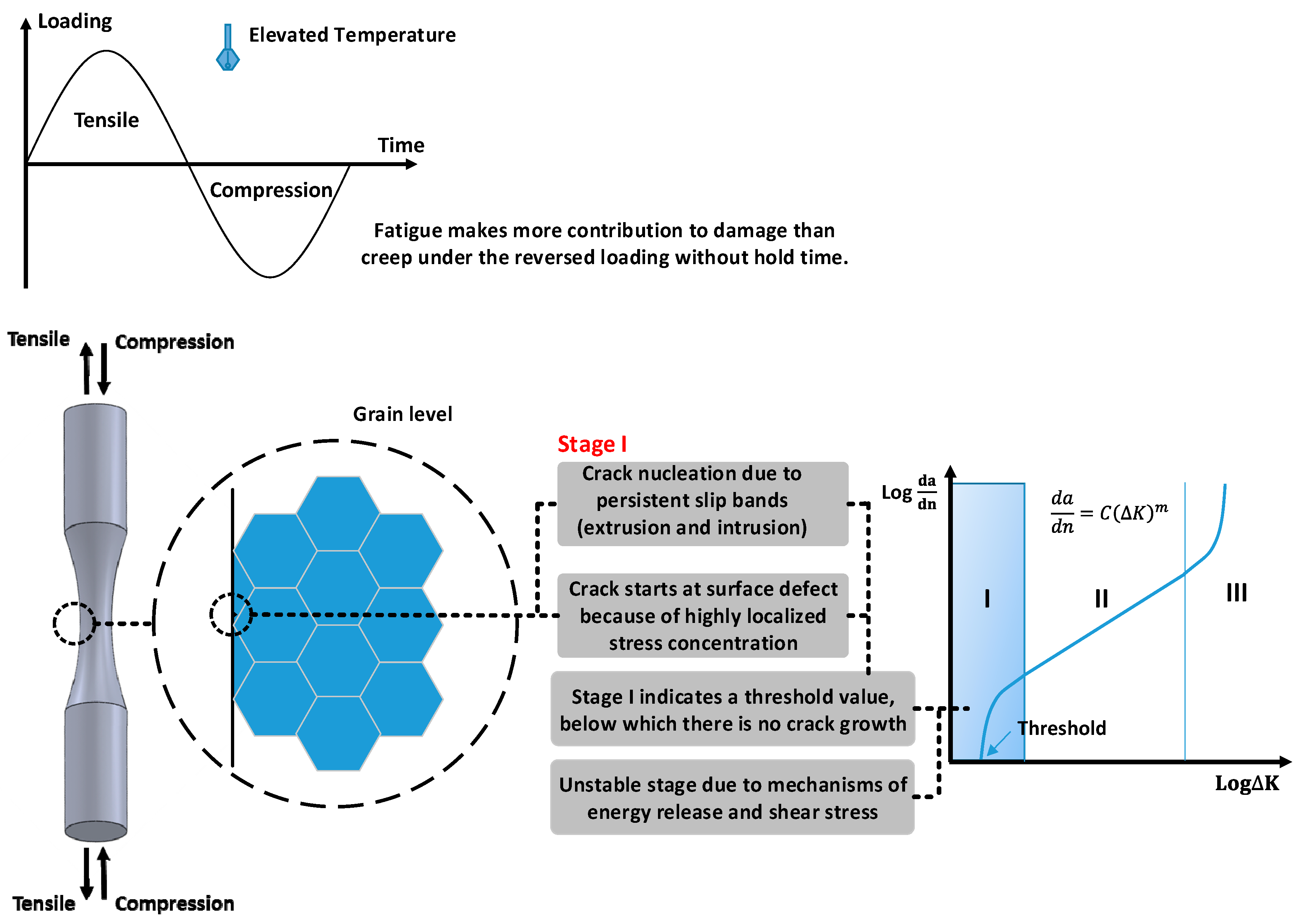
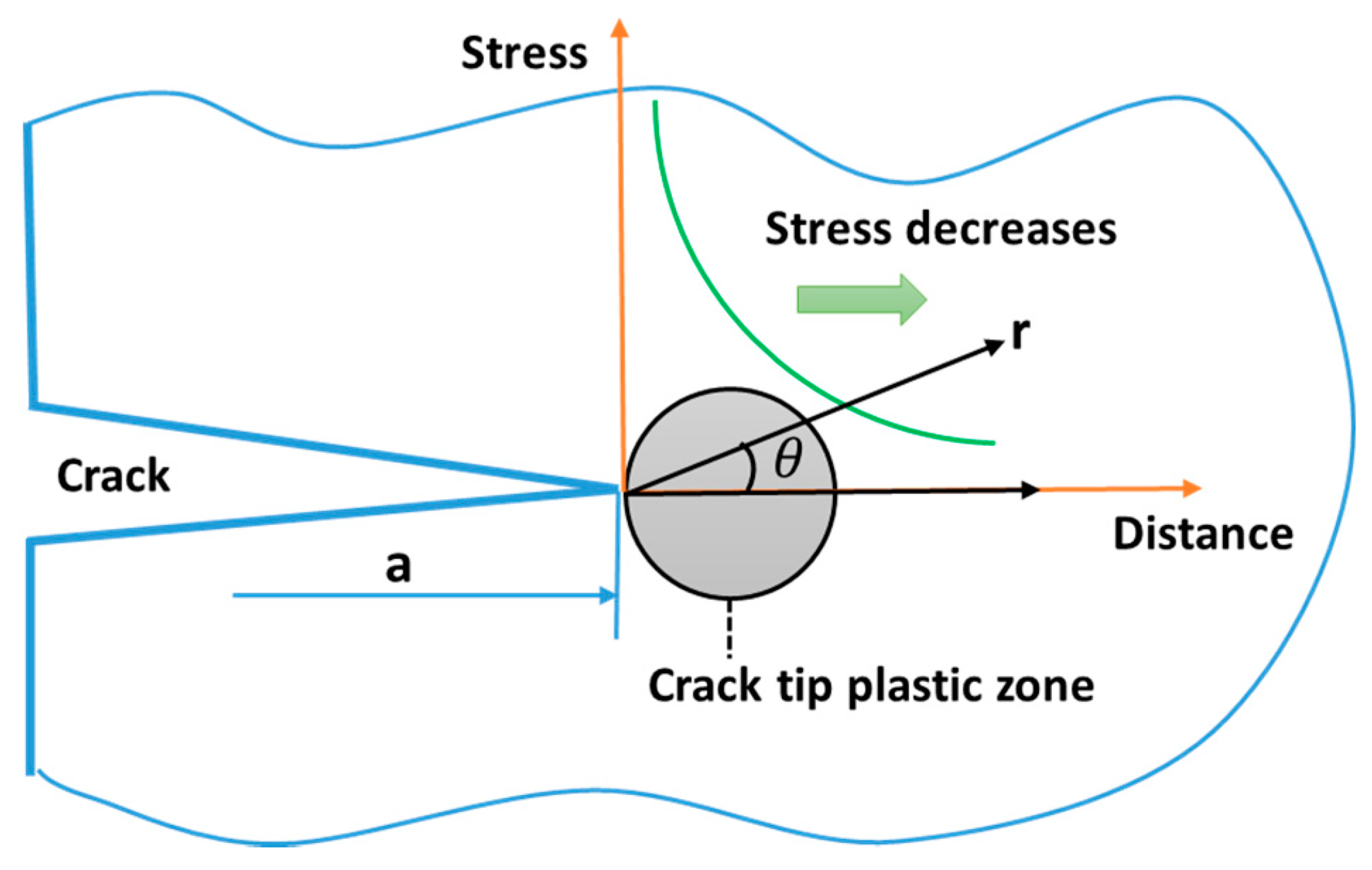
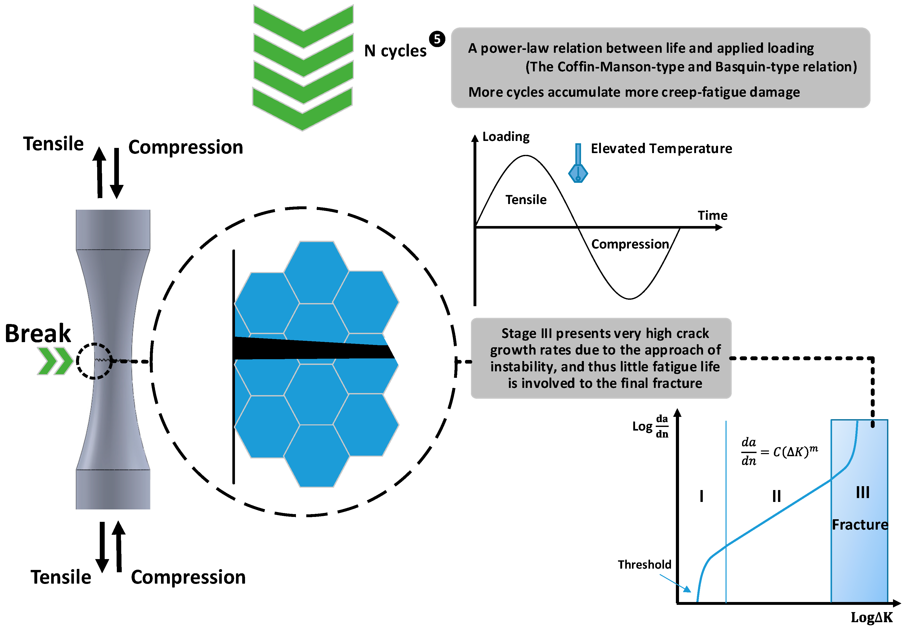
The strain energy release rate [20,21] determines the crack-growth rate. This mechanism underpins the unstable stage after the threshold of crack initiation. In this stage, increased energy accelerates the increase of crack-growth rate at the beginning phase, which is then retarded due to reduced energy and finally achieves a stable state.
(c)
The shear effects [22,23] provide opportunistic directions for crack growth. This mechanism involves the direction oriented at 45° providing a more favourable condition for crack growth at the initial phase of stage I.
Stage II: Crack propagation
(d)
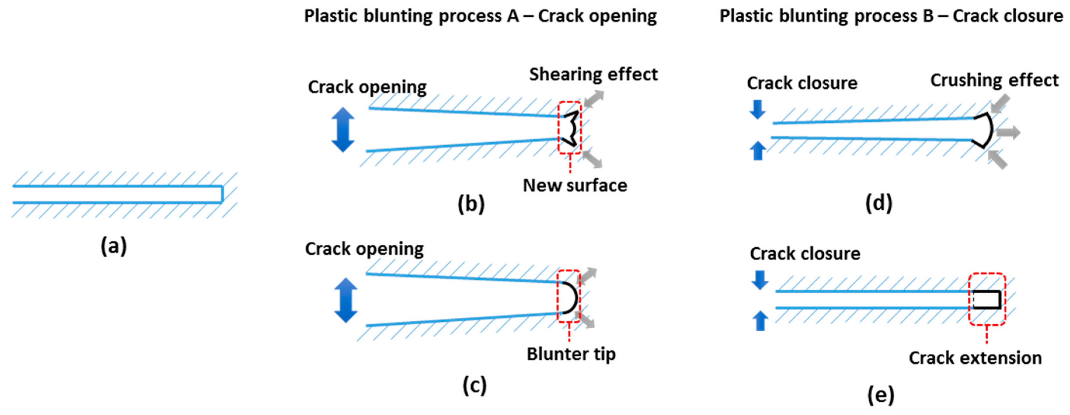
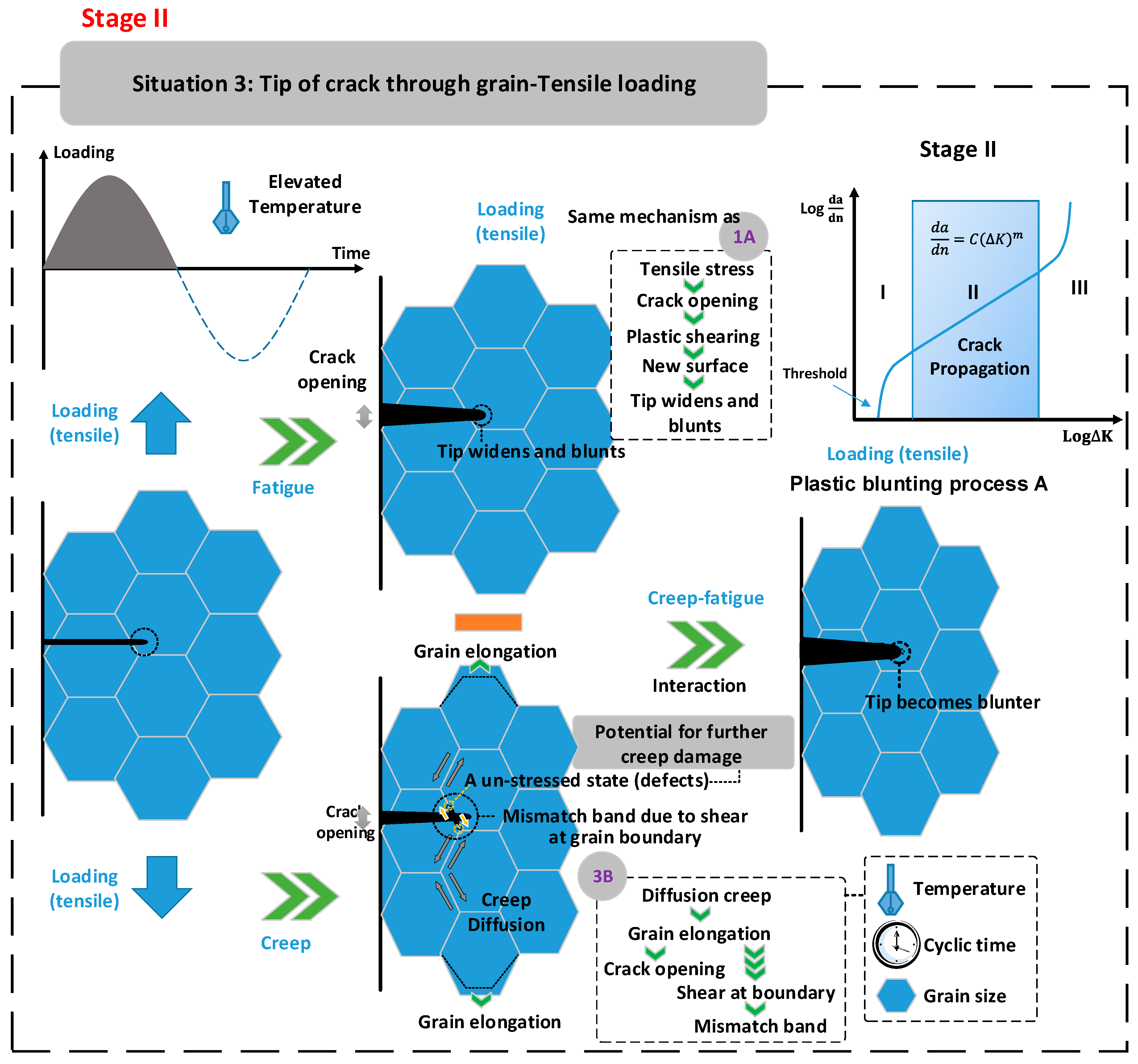
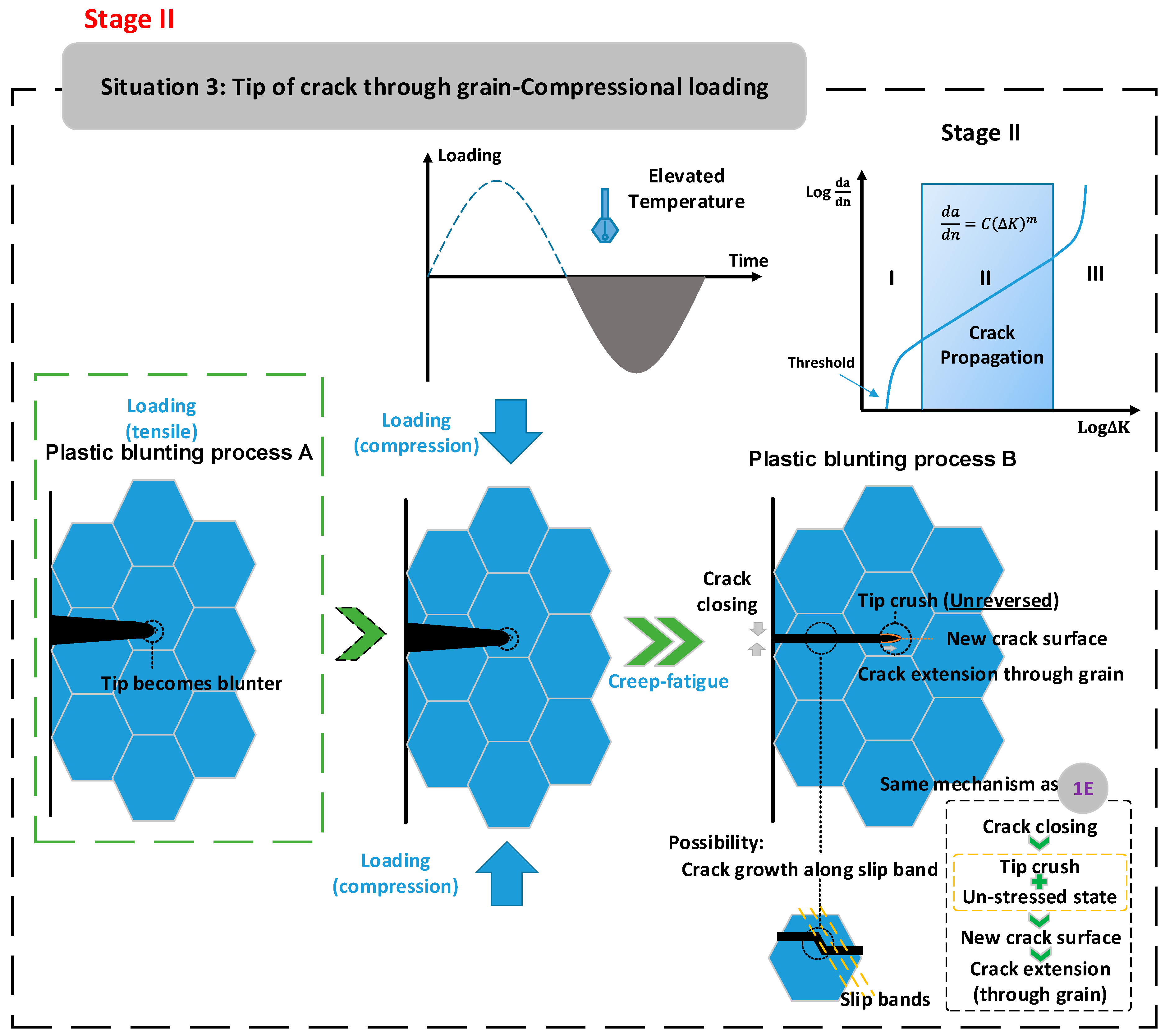
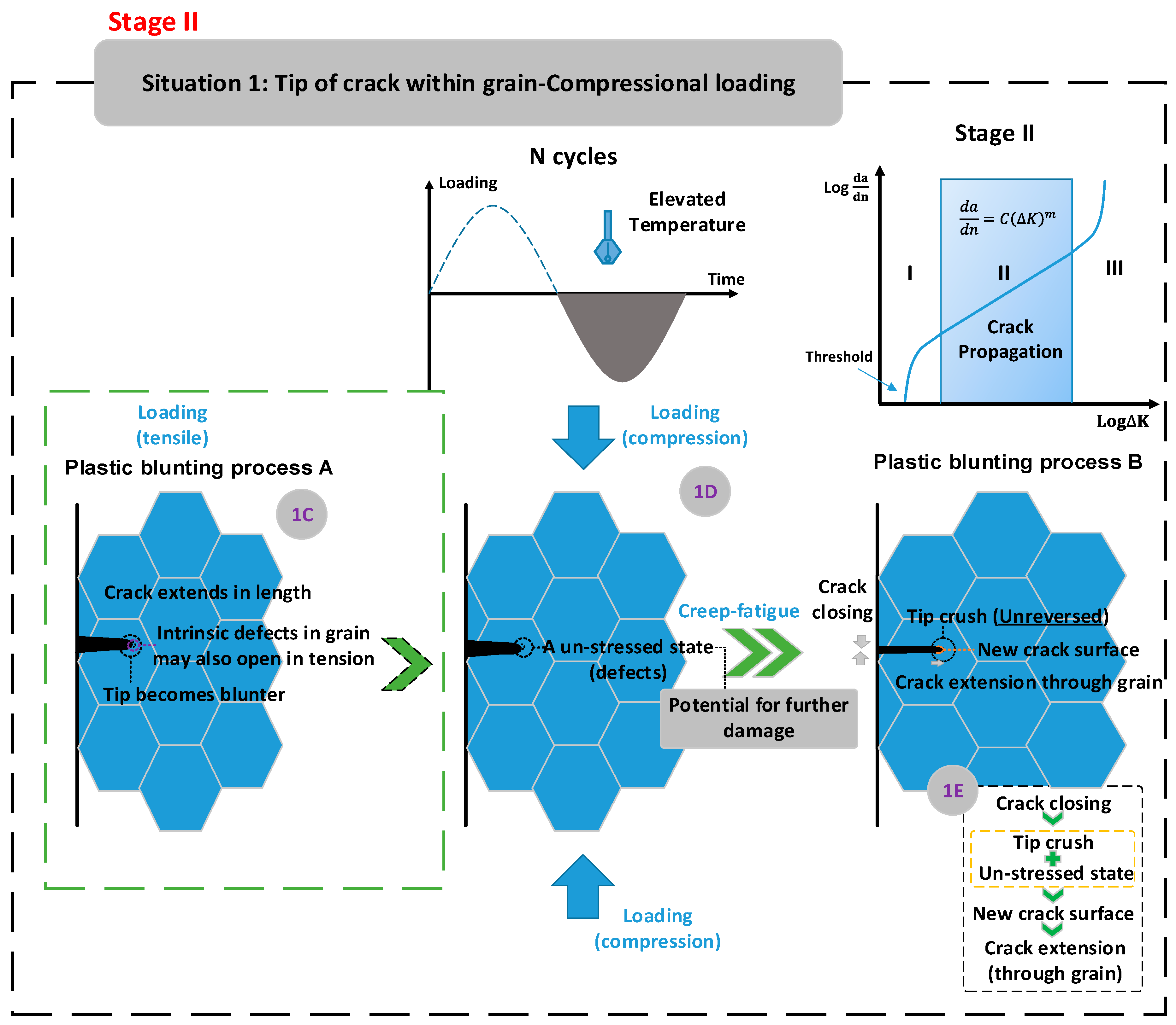
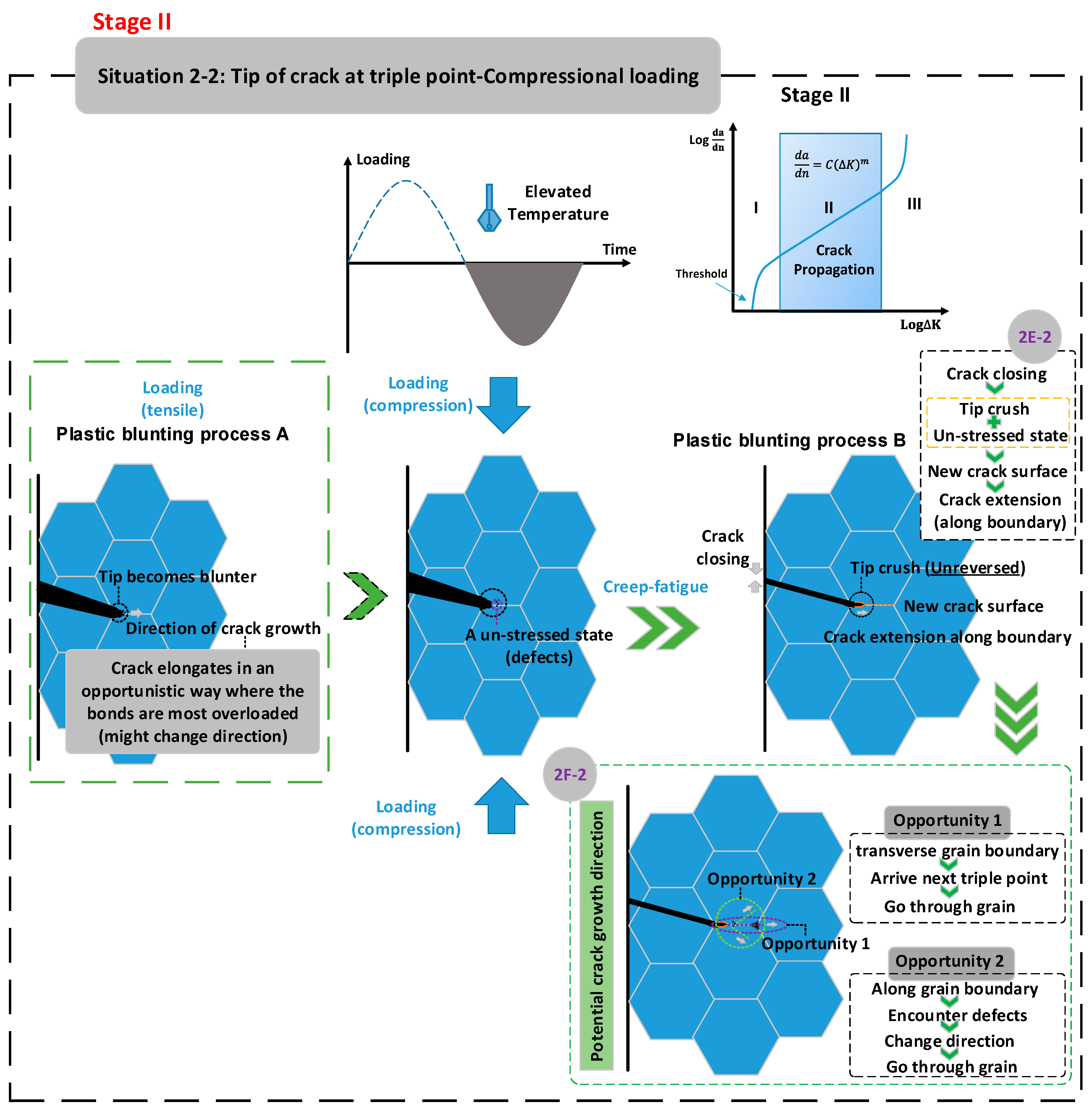
The plastic blunting process [24,25,26,27] has asymmetrical effects in the tensile and compressive loading cycles. This mechanism describes crack-growth behaviour in one loading cycle. The tensile loading blunts the crack tip, and the new crack surface is created due to a shearing effect. Then, when the loading is reversed, the surface created under tensile loading remains (crack extension) because of a crushing effect.
(e)
The crack tip plastic zone [28,29,30] enhances crack growth. This mechanism involves a highly localised stress around the crack tip. This, on the one hand, results in plastic deformation (crack opening) at the crack tip; on the other hand, it gives a more favourable situation for diffusion.
(f)
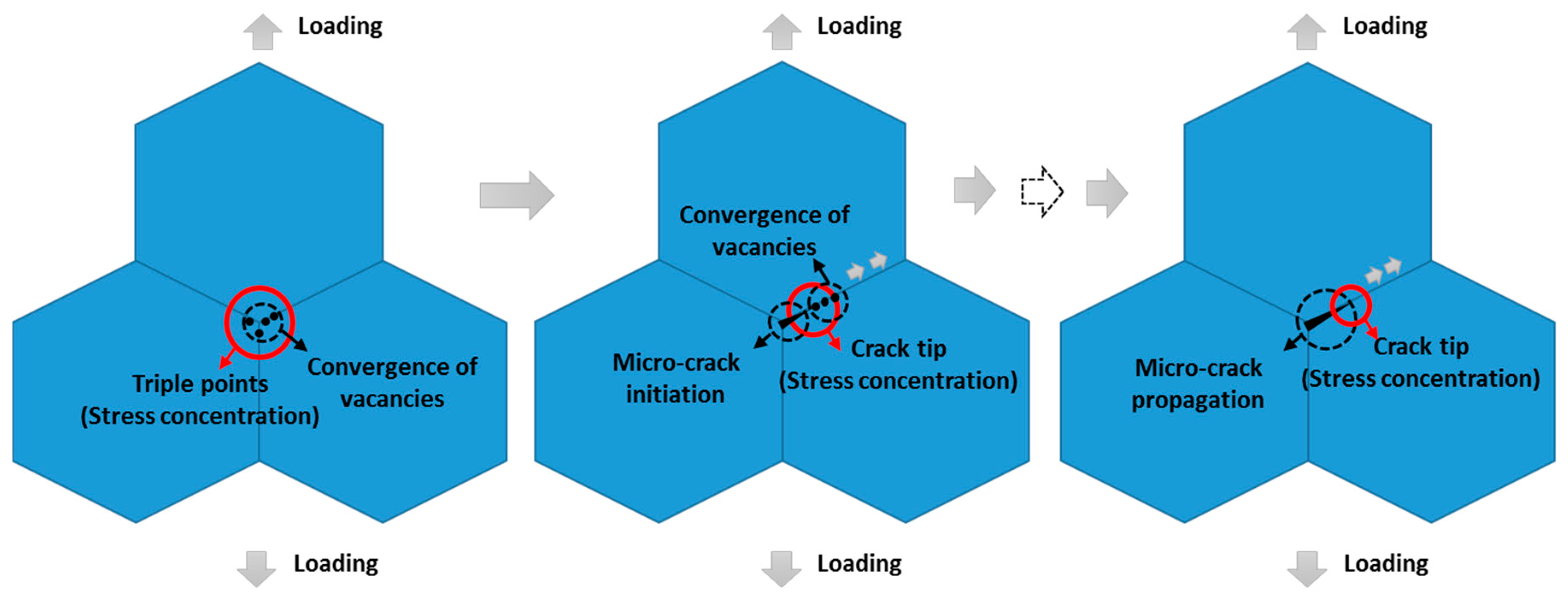
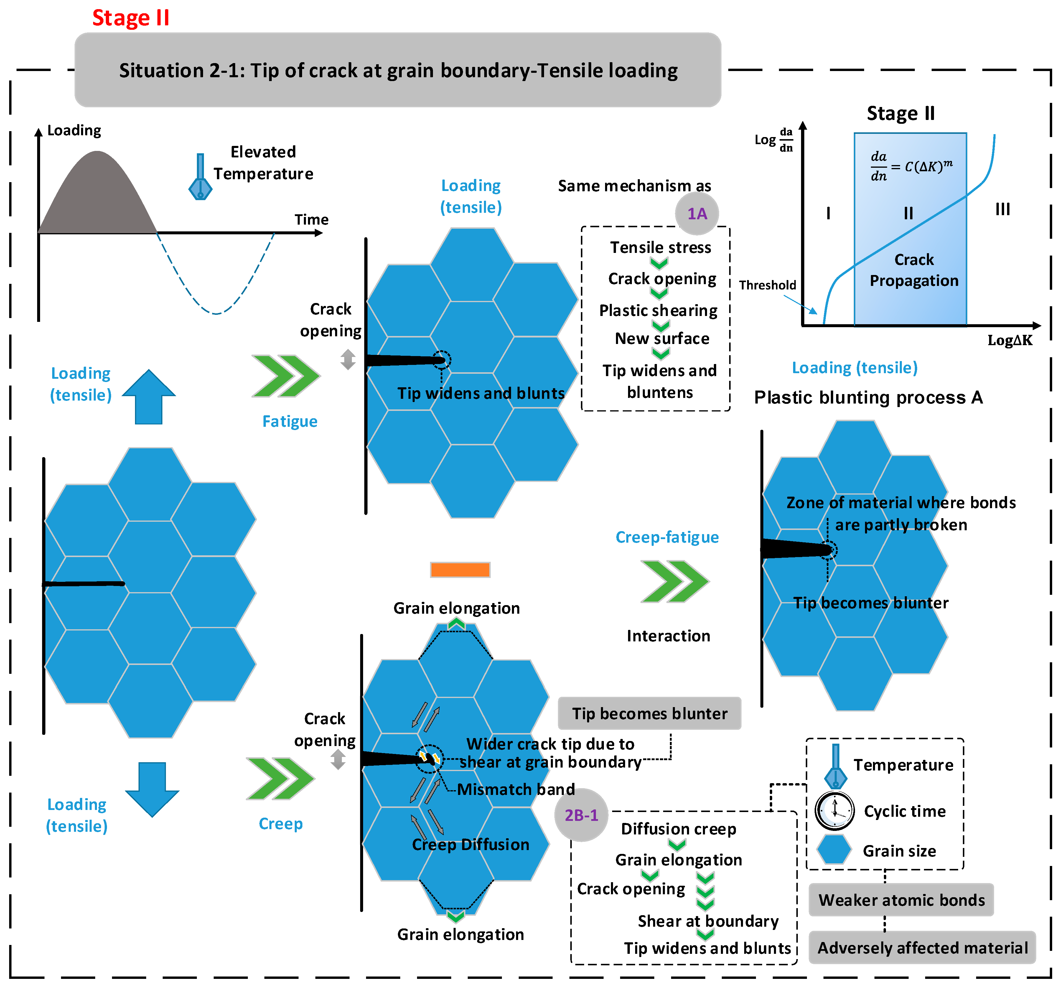
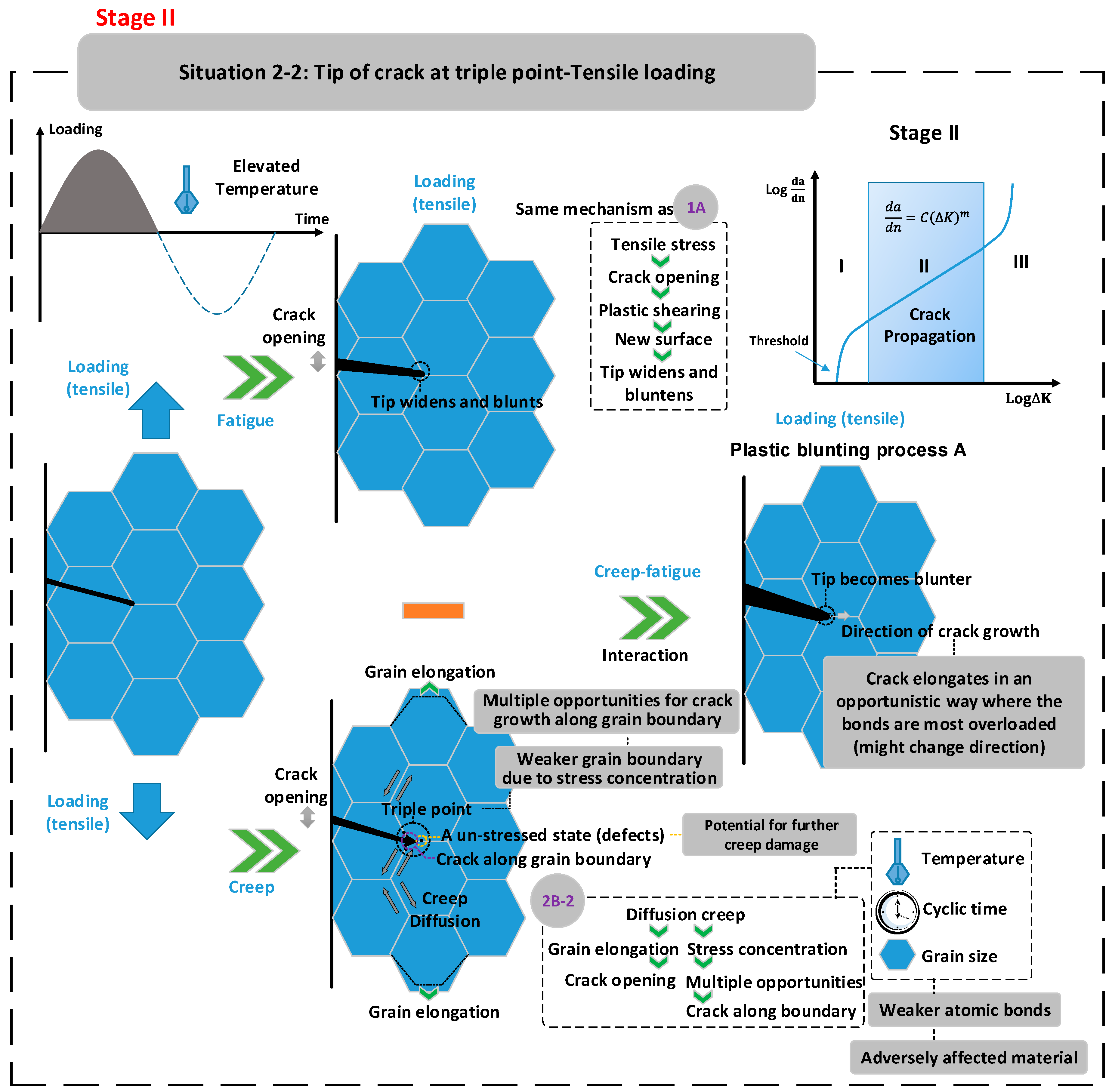
Diffusion creep [12,13] provides a mechanism that leads to grain elongation and then further crack opening. In addition, since atoms diffuse from a high- to a low-concentration region, more vacancies are generated and converged at the crack tip, where highly localised stress is presented, which provides a more favourable situation for creep damage.
(g)
Existing precipitates [31] cause fatigue resistance. The mechanism is mainly that precipitates are the obstacle to dislocation, and hence restrain the process of crack propagation.
(h)
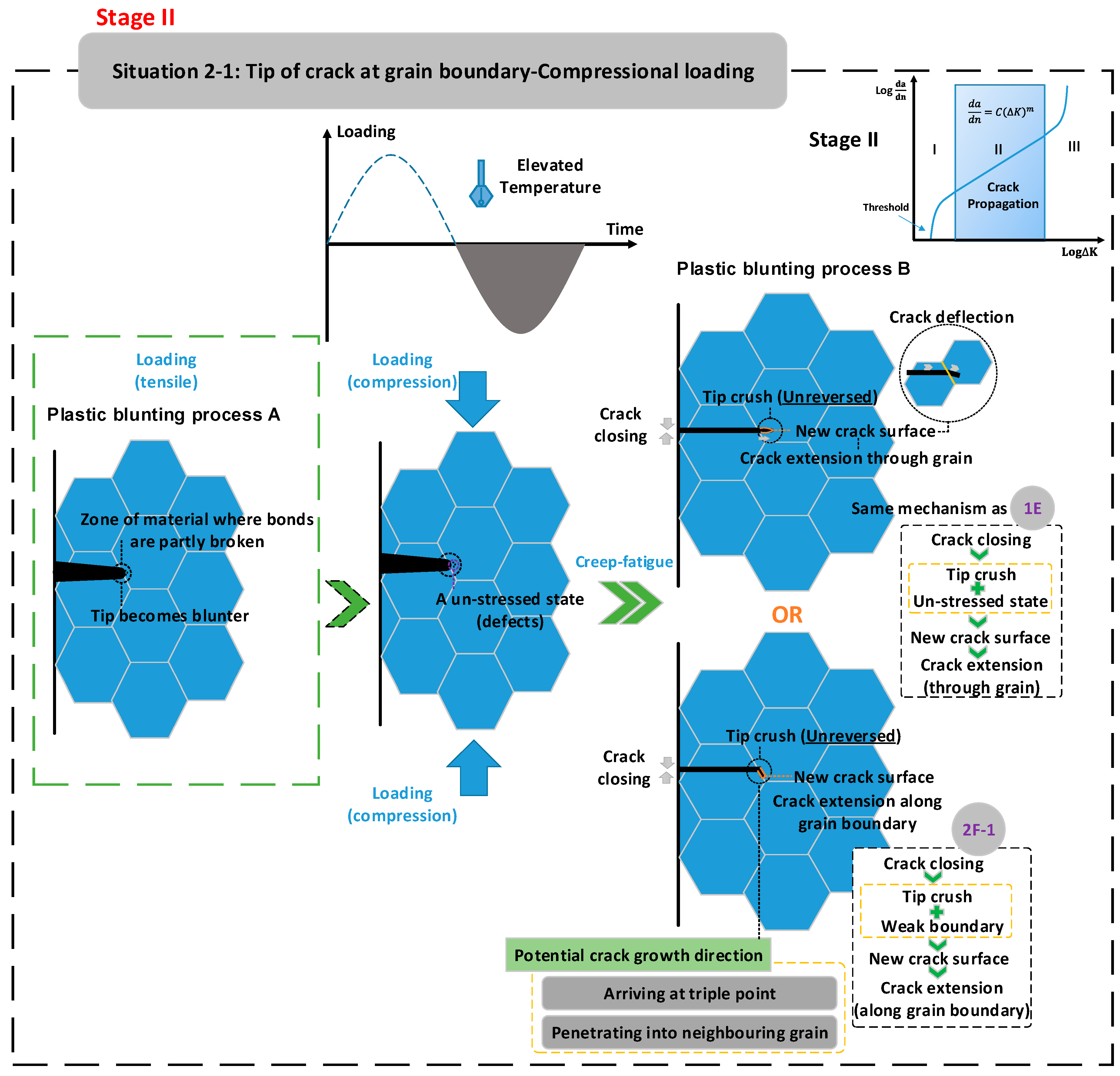
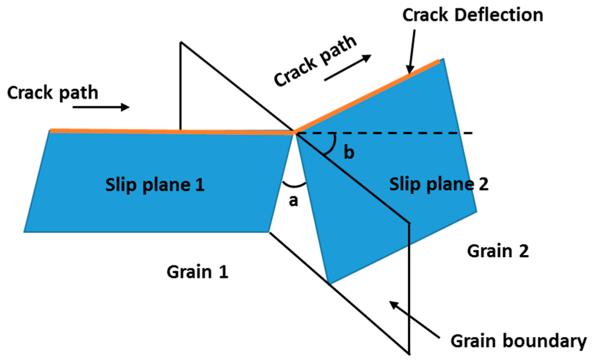
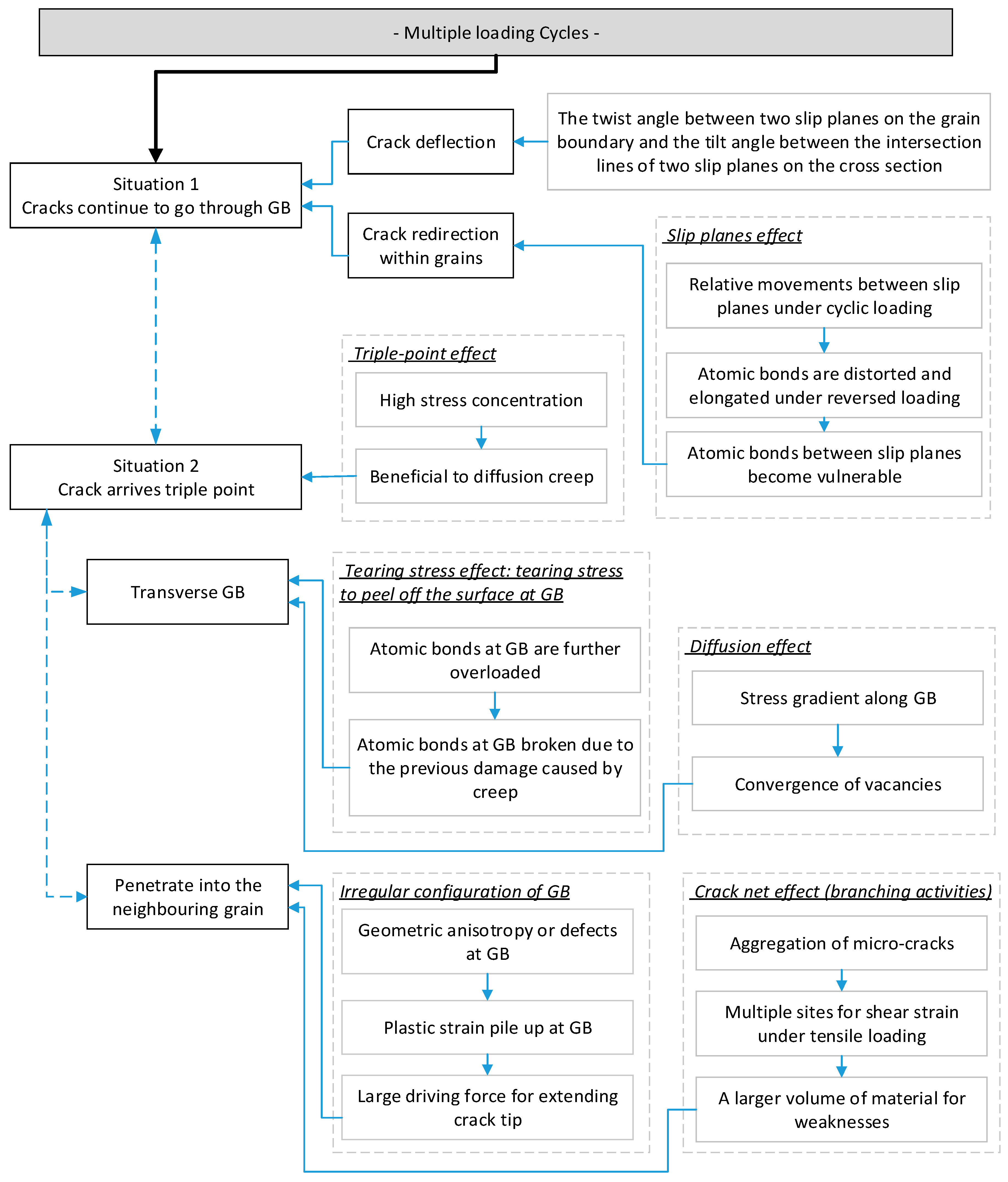
Crack deflection (change of direction) [32] preferentially occurs at the grain boundary. This is determined by the twist angle and the tile angle.
(i)
Triple-points [14,15,16] provide a mechanism for significant stress concentration, which provides a more favourable stress field for creep damage.
(j)
A region with a high density of micro-cracks is particularly weak, and supports crack-branching activities [33].
(k)
The slip bands within grains [34] may cause the crack to re-direct within grains.
Stage III: Structural failure
(l)
The plastic energy [23] available exceeds the need for producing the new crack surface. The excess energy is applied to form voids, and thus further worsens creep-fatigue resistance.

2.3. Gaps in the Body of Knowledge

Although the existing literature [22,23] indicates three stages of crack growth from initiation to failure, the implications of this for the behaviour of the crack at the grain-boundary effect is unclear. The grain boundary is known to play an important role in both fatigue-crack and creep-crack growth in different ways; hence, a grain-boundary effect cannot be ignored. Despite the apparent comprehensiveness of the above list of mechanisms, the literature contains many disparate findings without an obvious integration into a holistic theory for the crack propagation process.
Hence, there is a need to develop a framework to link these details together, to propose a coherent set of mechanisms for the steady stage of crack growth at the grain level, and to involve grain-boundary effects. This ideally needs to consider all the loading effects (fatigue, creep, and creep fatigue) at the microstructural level.

3. Approach

The approach in the present work was to start with existing principles of fatigue-crack and creep-crack growth (Section 2.2), and then conceptually develop a microstructural model of the creep-fatigue crack-growth process. This was achieved by imagining the process from the perspective of atoms in orderly grains and at the grain boundaries (where the orderly arrangement between atoms breaks down). The bonds between atoms inside a grain are strong, relative to the bonds between atoms at grain boundaries. We sought to identify a coherent set of mechanisms that would affect the bonds between atoms, for all the loading regimes. We integrated multiple existing concepts at the microstructural level, such as the plastic blunting process, the mechanisms of dislocation, and the diffusion creep process. These processes are extant in the literature, and our contribution is to integrate and apply them to the fine scale to give a new understanding of the interaction between the underlying mechanisms. In addition, a number of new mechanisms for crack growth were also proposed to construct a comprehensive conceptual framework.
Since the principles of crack growth of fatigue and creep are different (the fatigue effect occurs via cracks through the grains, while the creep effect involves the grain boundary cracking), the fatigue and creep crack-growth behaviours were discussed and illustrated separately. In this microstructural conceptual framework, three stages of crack growth from crack initiation to structural fracture were included. The second stage of steady crack growth is the primary focus. This is where the majority of the lifetime is consumed. It also presents multiple situations regarding the position of the crack relative to the grain boundary. The result is a proposed theory of the failure mechanisms, and this is represented in the form of a schematic representation, see Section 4.

4. Results

The microstructural conceptual framework mainly focuses on the second stage of crack growth. On the one hand, this is because this stage presents a stable process of crack growth and is numerically described by the well-known Paris’ Law [11]. On the other hand, this is because the majority of the lifetime is consumed at the second stage of crack growth for low cycle fatigue, and this fatigue regime is an important consideration when the creep effect is activated during the design process [8]. In this framework, the crack-growth behaviours under the tensile partition and compressional partition are discussed separately, and crack-growth behaviours caused by the fatigue effect and creep effect are described separately.

4.1. New Propositions

The challenge is showing how these multiple premises are integrated together at the microstructural level. There are no models and conceptual frameworks in the literature that provide such integration. To solve this problem, we propose several new effects. Our propositions of mechanisms that operate at the microstructural level during crack growth are:
A
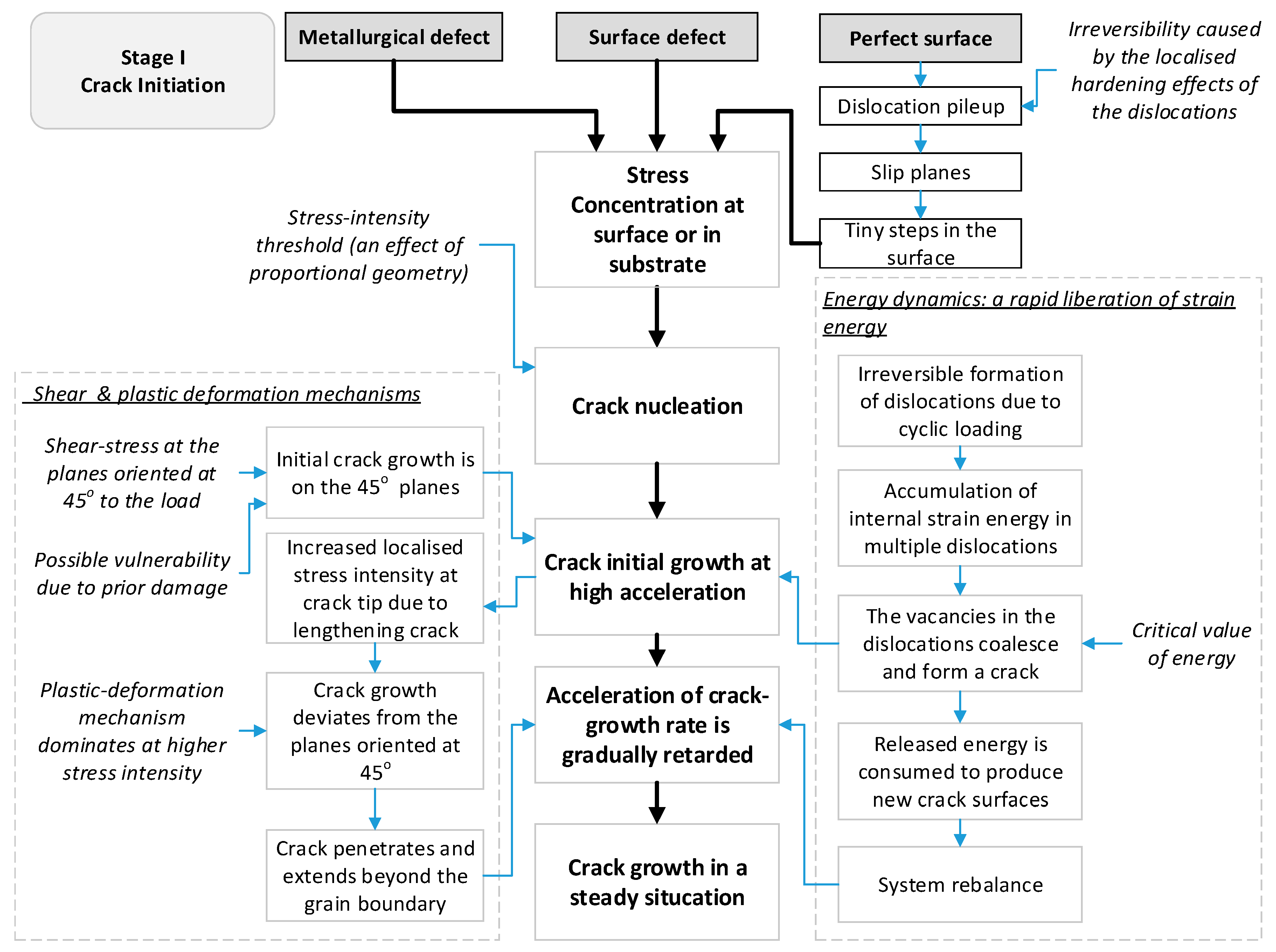
That energy dynamics explain the crack initiation and the following unstable phase, and is based on a liberation of energy due to coalescence of dislocations. In general, when the internal energy stored in the structure due to cyclic loading arrives at a critical value, the barrier to initiate the crack is overwhelmed. After this, the released energy is gradually consumed to produce new crack surfaces at an accelerated crack growth rate.
B
That grain-mismatch occurs due to grain elongation under the tensile loading, resulting in relative movement between two neighbouring grains. Then, the shear stress along the grain boundary is increased and a weaker region along the grain boundary is created. This results in a mismatch band at the grain boundary. This widens the crack body and enhances its growth.
C
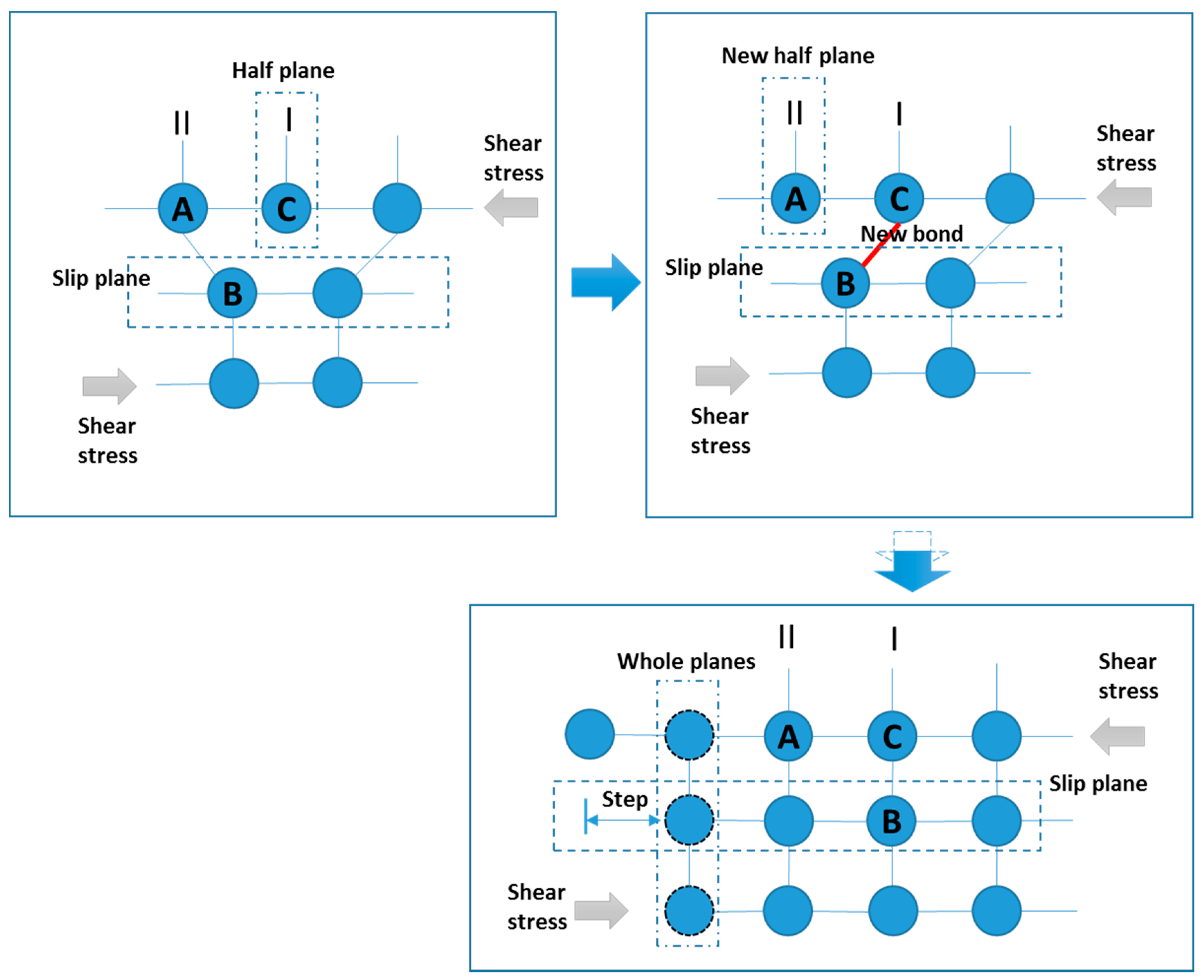
That bonding crushing effects exist at the finer scale. During the process of compression, the atomic bonds, which are distorted and rearranged in the tensile phase, may be further damaged and become potential failure sites for next loading cycle. This process is irreversible, since the atoms cannot return to their original position under the compressional loading.
D
That a crack net is caused by the aggregation of micro-cracks. This crack net probes a larger volume of material for weaknesses, and then promotes the main crack.
E
That irregular configuration of the grain boundary causes stress/strain pile up at the grain boundary, and then results in a large driving force for extending the crack tip into the neighbouring grain.
Furthermore, it is proposed that these mechanisms are integrated by the following assumptions:
F
That the primary mechanism for failure in the creep-fatigue loading regime is crack growth by mechanisms of crack blunting (including shearing and crushing); hence, fatigue effects.
G
That the supporting mechanisms that augment the extent of damage are grain elongation and diffusion; hence, creep effects.
We formulated these propositions as part of an iterative process of seeking a consolidated framework. Hence, the above are not so much lemmas that were asserted at the outset, but rather principles that were acquired during the framework development.
The resulting conceptual framework, shown below, is a fusion of the principles (Section 2.2) and propositions (Section 4.1) into a more extensive conceptual framework.

4.2. Conceptual Framework of Temporal Development of Crack-Growth for Creep Fatigue

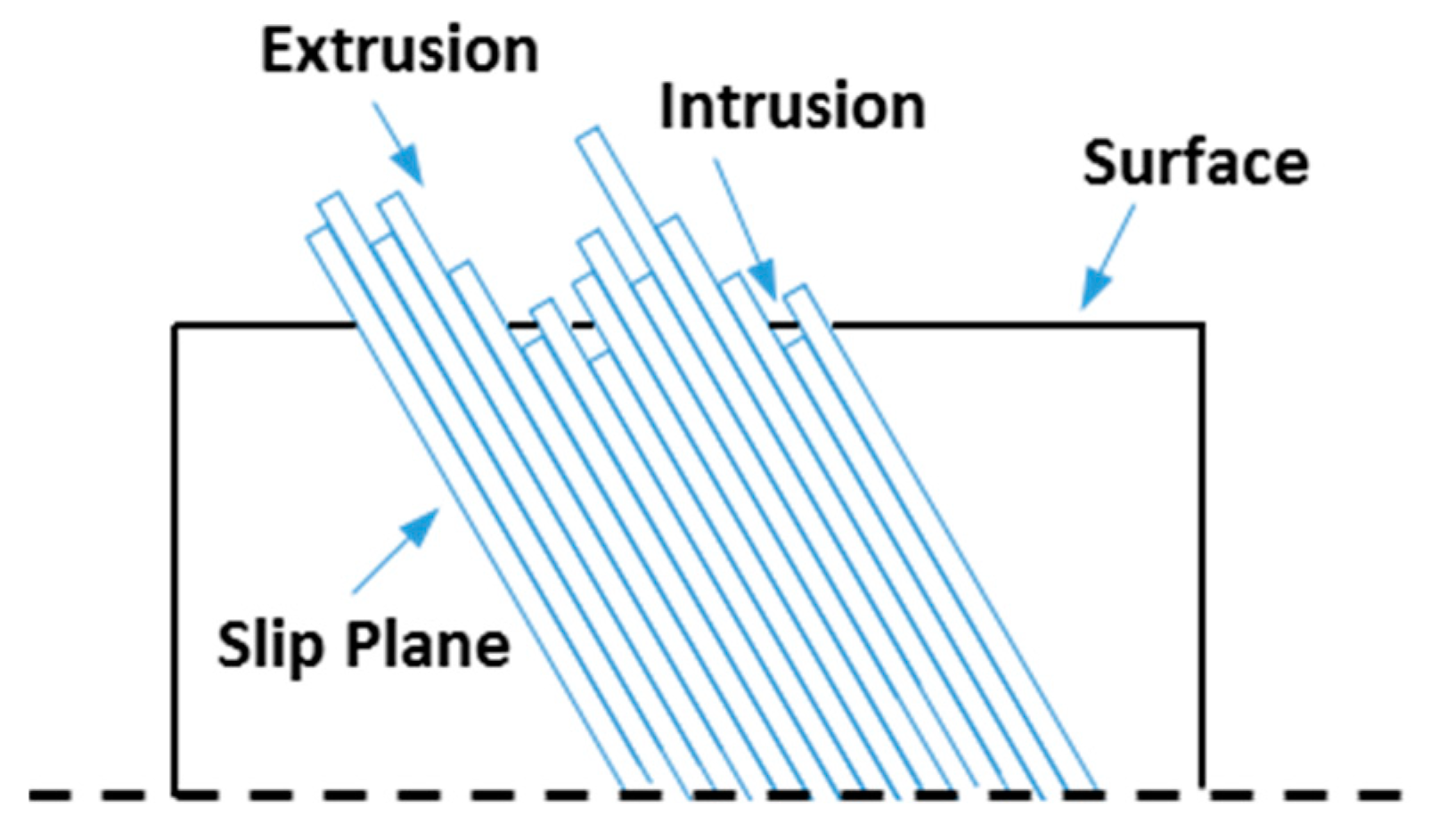
4.2.1. Stage I: Crack Initiation

The first stage (stage I) is that of crack initiation. We summarise the crack initiation mechanics as follows. Fundamentally, crack initiation is caused by stress concentration, where two situations are presented. A typical situation is that the crack starts at a surface defect such as a machining mark. This provides a highly localised stress concentration, hence a pre-existing micro-crack [8]. By this means, a crack is initiated at this specific point, and then the localised plastic strain caused by the ductile micro-tearing events provides opportunity for further propagation.
Second, for a situation with perfect surfaces (defect-free), dislocations play an important role [19] for the initiation of a fatigue crack [35] (Figure 1.9 therein), [36] (Figure 1 therein). During this process, loading cycles cause dislocations to pile up at the microstructural level. These dislocations are in the crystal lattice at the nanoscale. Under loading, they align and coalesce to produce thicker slip planes through the crystal and eventually slip bands at the macrostructural level [37]. Under cyclic loading, there is more relative movement between the bands, so the effect becomes more pronounced—the bands are further displaced. We suggest that this is due to irreversibility caused by the localised hardening effects of the dislocations.
In the area of persistent slip bands, the slip planes extrude or intrude to the surface of the object, see Figure 4. This results in tiny steps in the surface, where the stress concentration then results in crack nucleation.
In stage I (the crack-initiation stage), a crack-growth threshold exists. In general, there are two types of thresholds [38]: microstructural and mechanical. The microstructural threshold describes the initiation of micro-cracks at different microstructural features, such as slip bounds and cavities. The mechanical threshold is related to macroscopic geometry for long crack growth, and is discussed in the present work. Below this latter threshold, there is ordinarily no crack growth [8]. We attribute this to the cracks being too short to result in a meaningful stress concentration effect (which is primarily an effect of proportional geometry). Also, if there are many superficial defects at the surface—which is usually the case—then the material does not have a geometrically exact boundary at the nanoscale, and hence the stress avoids this region: the many small defects effectively decrease the stiffness of the superficial layer, and hence this layer is to some extent unloaded.
After the threshold stress intensity is exceeded, there is a regime of high acceleration of crack-growth rate. Then, following this high-acceleration regime, a transition to a slower acceleration of crack-growth rate is presented.
On the one hand, this process is attributed to the concept of strain energy release rate, which describes the energy consumed per unit of newly created crack surface. This implies that the more strain energy is released, the more new crack surfaces are produced. Normally, the strain energy release rate could be numerically related to the M-integral [20,21]. The relationship between the number of cycles and M-integral was investigated by Margaritis [39] (Figure 7 therein), where the M-integral increases with the increasing number of cycles at the early phase, then it decreases over the peak, and finally it reaches a constant situation. This trend is consistent with observation of the initiation stage shown in Figure 1. Specifically, after the threshold, increased energy (released strain energy) accelerates the increase of crack-growth rate at the beginning phase, then reduced energy retards the acceleration of the crack-growth rate, and finally a steadily increasing crack-growth rate is achieved under a situation with constant energy (this is viewed as the crack-propagation stage).
We suggest that the underlying energy dynamics are based on a rapid liberation of energy due to coalescence of strain. Specifically, the internal energy, which is stored in the structure in the form of the irreversible formation of dislocations that increase in number due to cyclic loading. Then, when this energy arrives at a critical value, the vacancies in the dislocations coalesce and form a crack—hence breaking through the barrier to initiate the crack. This qualitative leap from perfection to imperfection requires internal energy. This process is accomplished during a short time period by releasing large amounts of energy. After this, the released energy is consumed to produce new crack surfaces in a high acceleration of crack-growth rate, and the whole system is forced into an unsteady condition. Naturally, the need to re-balance this system gradually reduces the amount of released energy (caused by applied loading) until a balanced condition is reached. During this process, the high acceleration of crack-growth rate is gradually retarded, and then this acceleration reaches stabilisation (the whole system is re-balanced). The growth of the crack causes further large-scale deformation of the grain as a whole, which causes more dislocations to occur within the grain, and repeats the cycle.
An alternative explanation is that the unstable behaviour of crack growth in stage I is due to shear mechanisms [22,23]. Generally, a crack is propagated through two different methods: the plastic deformation around the crack tip and the shear-stress effect at the planes oriented at 45° to the loading direction. During the initial phase of crack growth, a small plastic zone and a small stress field are presented around the crack tip because of the small magnitude of stress intensity. In this case, the mechanism of plastic deformation around the crack tip may not be significant enough to become the driving force for crack growth. Instead, the shear stress at the planes oriented at 45° provides more favourable conditions for crack growth. This is because the shear stress at these planes and the relative movements between these planes under cyclic loading provide more vulnerable areas for crack growth. Prior damage and lattice imperfections may exist on these planes from previous loading cycles. In this case, a crack grows along the planes oriented at 45° with a minimum of effort, hence resulting in a high acceleration of the crack-growth rate.
As the stress intensifies, the shear-stress effect is gradually suppressed by the plastic-deformation mechanism; hence, the acceleration of crack-growth rate is reduced. This is because, during this process, the direction of the crack growth gradually deviates from the surface of the planes oriented at 45°, and then the behaviour of penetrating the grain boundary results in the deceleration of crack-growth rate. Finally, crack-growth behaviour is stably caused by the crack-tip plastic zone, and a steady situation is achieved (stage II is initiated).
We suggest that both mechanisms apply, and complement each other. The key elements (mechanisms) in the crack initial stage are presented by Figure 5.
We summarise the crack initiation mechanics as follows, see Figure 6. Crack nucleation starts at the surface due to highly localised stress concentration. In the case of smooth surfaces, it is attributed to the presence of persistent slip bands (extrusion and intrusion). Stage I (the stage of crack initiation) has a threshold value, below which no crack growth occurs. Once a crack is initiated, it grows quickly at the early phase, then the acceleration of crack-growth rate is reduced, and the crack-growth behaviour finally becomes steady (see next section). This process is proposed to be underpinned by the above mechanisms of strain energy release and shear stress.

4.2.2. Stage II: Crack Propagation

The second stage (stage II) shown in Figure 1 presents the behaviour of crack propagation, wherein the crack growth undergoes a relatively steady process. This stage is numerically presented by Paris’ Law (Equation (1)) [11], which shows a power-law relationship between the crack growth rate and the range of the stress intensity factor during the fatigue cycle:
  d a d n = C ( Δ K ) m  
where d a d n is the crack growth rate; Δ K is the effective stress intensify factor, which is identified as the difference between maximum and minimum stress intensify factors for one cycle; K is the stress intensify factor; a is the crack growth; n is the number of cycles; and C and m are constants.
The crack-growth process of creep fatigue is mainly discussed under the second stage of crack growth, and this discussion is based on the idea of the plastic blunting process [24,25,26,27].
At the beginning of the loading cycle, the crack tip is sharp (Figure 7a). Then, the applied tensile stress leads to crack opening, and the stress concentration at crack tip causes the slip along planes at 45° (Figure 7b). This leads to the gradual increase of crack-tip area, and finally the crack tip widens to its maximum plastic deformation (Figure 7c) due to the plastic shear effect. At the same time, the crack tip becomes blunt and grows longer because a new crack surface is created.
When the loading is changed to a compressional situation, the crack is closed, and the slip at the crack tip is reversed (Figure 7d). Finally, the crack surfaces are crushed together, and the new crack surface created under tensile loading remains (Figure 7e) (crack extension). Consequently, the sub-cracks promoted by each loading cycle are accumulated, and the structure fails as the total damage achieves a critical value.
The idea of plastic blunting process was integrated with a general understanding of creep mechanism to show crack-growth behaviour of creep fatigue. The process of crack propagation (Figure 8, Figure 9, Figure 10, Figure 11, Figure 12, Figure 13, Figure 14, Figure 15, Figure 16, Figure 17, Figure 18 and Figure 19) is described (at a grain-based level) by three typical situations: (1) crack tip within a grain (Section 4.2.2.1); (2) crack tip at the grain boundary (Section 4.2.2.2 (1)) or at the triple point (Section 4.2.2.2 (2)); and (3) crack tip through grain boundary (Section 4.2.2.3).
In the present work, fatigue is identified as crack growth by overloaded local atomic bonds, and creep is regarded as the flow of atoms relative to each other with transfer of bonding to new partners.

4.2.2.1. Crack Tip within a Grain

■ Conceptual framework for crack growth in the tensile regime
Under tensile loading (Figure 8), the fatigue component follows the idea of the plastic blunting process. In this process (1A in Figure 8), tensile stress leads to crack opening, and shear behaviour is presented at the crack tip. Then, by the plastic shear effect, the new surface is created; meanwhile, the crack tip widens and becomes blunt (the blunting behaviour was illustrated in Figure 12 in Ref. [40] and Figure 32 in Ref. [41], where a stretch region is presented). Diffusion creep is identified as the main creep mechanism for creep-fatigue damage in the present work. It is generally believed that diffusion creep leads to grain elongation, which then results in a further opportunity for crack opening (1B in Figure 8).
In addition, diffusion creep has a dependency on applied loading, and larger loading produces more creep damage. Specifically, the idea of a crack tip plastic zone [28,29,30] indicates that the localised stress is highly significant around the crack tip, and gradually decreases in the direction of crack growth (Figure 9). In particular, under the theory of linear elasticity, stress distribution around the crack tip can be numerically presented as (Equation (2)):
  σ i j = σ a 2 r f ( θ ) = K 2 π r f ( θ )  
where σ i j is the stress distribution, a is the crack length, K is the stress intensity factor, and r and θ are polar coordinates. This equation encapsulates a stress-concentration phenomenon around the crack tip. This relation is commonly accepted as being applicable to the creep-fatigue condition on the assumption that the crack-tip plastic zone is small. Higher localised stress around the crack tip causes more creep damage due to increased diffusion, and thus contributes to crack opening. Specifically, atoms normally diffuse from a region of high concentration to a region of low concentration. In this case, more vacancies are generated and converged at the crack tip, and then a more favourable situation for creep damage is presented.
Consequently, the crack tip surface caused by the fatigue effect is further extended and becomes blunter due to the creep effect (1C in Figure 8), which implies the combined effects of fatigue and creep. A defected-related state, such as intrinsic defects, around the crack tip may also promote crack growth (negative to fatigue resistance), where the weakest zone of atomic bonds is represented. An example of presenting a defected-related effect is shown in Figure 32 from [41], where the crack is promoted due to void coalescence and the bridges between voids are sheared off. In addition, precipitates may also be considered to be defected-related effects, but ones which are normally beneficial to fatigue resistance. On the one hand, this benefit results from the obstacle to further dislocation [31], whereby the precipitates restrain the process of crack propagation. On the other hand, this benefit could also be explained by the fatigue-softening behaviour [42]. Generally, softening behaviour is caused by disordering the stacking sequence of precipitates due to reversed loading, whereby the crack encounters a tougher situation to penetrate this area. In addition, the fatigue-softening behaviour can also be attributed to the reduced area intercepted by the dislocation of the slip planes due to the gradual consumption of precipitates under the reversed loading (the precipitates are cut into smaller sizes under reversed loading, and thus are dissolved).
Creep effect has strong dependencies on temperature, cyclic time and grain size [43]. Generally, a higher temperature leads to more creep damage, and a linear relation between temperature and applied loading is presented (❶ in Figure 8). In addition, a longer cycle time gives more creep damage, and a logarithmic relation between cyclic time and temperature is presented (❷ in Figure 8). Furthermore, a small grain size is positive for fatigue while big grain size is beneficial for creep resistance, and a power-law relationship between grain size and applied loading is presented (❸ in Figure 8). Consequently, the negative creep effect caused by elevated temperature, or prolonged cyclic time, or smaller grain size gives weaker atomic bonds; then, this results in adversely affected material. The concept of ‘fatigue capacity’ indicates that the total fatigue capacity is gradually consumed by creep effect. This process is numerically presented by taking the form of “1-X” (❹ in Figure 8) [43,44].
■ Conceptual framework for crack growth in the compressional regime
Under compressional loading, crack closure is presented based on the idea of the plastic blunting process, see Figure 10. In this process, the crack surface, especially the tip zone, is crushed together. Since the crushing process is inelastic and irreversible, the new crack surface created under tensile loading remains (1E in Figure 10). This implies that compressional loading also contributes to crack growth.
This phenomenon may be explained by the observation of the crack tip opening displacements [45,46] under compressional loading, where the crack is not entirely closed in this loading regime due to the plastic effect (this is illustrated in Figure 3 of Ref. [45]).
In addition, the contribution of compressional loading may also be explained by the behaviour of atomic bonds. Specifically, creep fatigue does its damage in the tensile phase by changing the landscape of atom arrangements and hence the bond vulnerability (which implies the bonds are extended and become weaker). During the process of compression, because of the crushing effect, some of these partly broken bonds may be further damaged and become potential failure sites for the next loading cycle, while others may be totally damaged and then lead to crack extension. This is significantly not a reversible process, since the atoms cannot return to their original positions after one tension-compression cycle. Furthermore, the defect-related state around the crack tip may further propagate cracks due to the crushing effect. Specifically, the crushing effect causes the crack tip to be squeezed, and then the tip is possibly extruded towards the zone with the weak atomic bonds. In this case, the crack is further extended (1D in Figure 10) by cutting these vulnerable bonds with the assistance of the crushing effect. Consequently, the sub-crack under one loading cycle is formed, which contributes to the final fracture.
After N cycles, the accumulated crack arrives at the grain boundary or it encounters the triple point. This results in the following situation.

4.2.2.2. Crack Tip at Grain Boundary or Triple Point

(1) Crack tip at grain boundary
■ Conceptual framework for crack growth in the tensile regime
Under tensile stress (Figure 11), the fatigue component experiences the same process shown in ‘situation 1-1A’, wherein the new crack surface is created due to the plastic shearing effect. Then, this causes the crack tip to widen and become blunt. For the creep component (2B-1 in Figure 11), diffusion creep results in grain elongation along the stress direction. On the one hand, this results in crack opening, which was discussed in Section 4.2.2.1; on the other hand, shear stress, which results from grain elongation, leads to elongation of the grain boundary, which then causes the crack tip to widen; meanwhile, a mismatch band appears [47,48]. Specifically, the grain boundary presents a zone of irregular atomic bonds, and thus the bonds at the grain boundary present anisotropic behaviour. Therefore, the relative movement of points caused by grain elongation at the grain boundary may present different results, the extension or breakage of atomic bonds. This results in a zone of material where bonds are partly weakened, and provides potential for further damage. Consequently, creep intensifies the plastic blunting process caused by the fatigue effect, and a blunter crack tip arises.
■ Conceptual framework for crack growth in the compressional regime
In the situation with compressional loading (Figure 12), the same creep-fatigue process shown in ‘situation 1-1E’ is presented, where reversed loading crushes the material ahead of the crack, even across the grain boundary. As a result, the new crack surface caused by the tensile loading remains, due to the tip-crush effect, and the crack is further extended across the grain boundary.
In particular, the crack path may be deflected (this behaviour is illustrated in Figure 12 of Ref. [49]) at the boundary. Specifically, crack deflection at the grain boundary is generally determined by the twist angle (a) between two slip planes on the grain boundary and the tilt angle (b) between the intersection lines of two slip planes on the cross section [32]. This behaviour is illustrated in Figure 13, where the crack path is redirected at the grain boundary of the sample surface.
Alternatively, the tip-crush effect during the process of crack closure may lead to crack growth along the grain boundary. Specifically, grain band sliding, which occurs during crack opening, may result in a weaker region along the grain boundary. This then provides a more likely direction for crack propagation than the direction passing through the grain boundary. After this, the crack may arrive at a triple point or may penetrate into the neighbouring grain (deviated progression along the grain boundary). These two situations will be discussed in the next section.
(2) Crack tip at triple point
■ Conceptual framework for crack growth in the tensile regime
The triple point, which is defined as the connection point among three adjacent grains, provides a different crack-growth mechanism for fatigue and creep. Specifically, the fatigue effect under tensile stress (Figure 14) presents the same process shown in ‘situation 1-1A’, where a blunt tip is presented at the triple point according to the idea of plastic blunting process. Compared with the situation shown in Section 4.2.2.2 (1), creep presents a different behaviour at the triple point. On the one hand, diffusion creep results in grain elongation along the direction of tensile stress, and then this leads to crack opening (2B-2 in Figure 14); on the other hand, the triple point presents a significant stress concentration [14,15,16], which provides an effective stress field for crack growth along the grain boundary (2B-2 in Figure 14). In this situation, multiple opportunities arise for crack propagation along the grain boundary. Generally, the weakest microstructural zone will finally determine the direction of crack growth. Specifically, the weakest zone shows an intensified state, which is normally caused by defects. These include vacancies, which are beneficial to diffusion creep [10,50], and micro-cracks, which aggravate the concentration of stress and hence provide favourable conditions for diffusion. These defect-related effects may also change the direction of crack growth. In addition, according to the idea of the crack tip plastic zone (shown in Figure 9), the stress concentration is presented at the crack tip, where a strong high-stress field is provided hence more creep damage is produced. This implies that this area/direction may have more potential for crack growth. As a result, with the combined effect of fatigue and creep, a blunter crack tip is presented. The crack grows opportunistically in the direction where the grain boundaries are most vulnerable (for propagation into the grain see below).
■ Conceptual framework for crack growth in the compressional regime
Under compressional loading (Figure 15), according to the idea of the plastic blunting process, the crushing effect maintains the new crack surface created under the tensile situation, and thus the crack is extended along the grain boundary (2E-2 in Figure 15).
Crack growth in the next cycle or the next few cycles may have two possible paths (2F-2 in Figure 15). Specifically, on the one hand, a crack may traverse (or grow along) the grain boundary, where the weakest atomic bonds are present. This may be attributed to stress concentration at the grain boundary, since the existence of the stress gradient results in the convergence of vacancies [12,13], and in particular, the vacancies at the grain boundary provide favourable conditions for diffusion creep [10,50]. In this case, the crack along the grain boundary gradually accumulates, and then reaches the next triple point, where the opportunity for re-direction is provided.
On the other hand, the crack may be deflected away from the grain boundary. This behaviour is illustrated in Figure 3 of Ref. [47] and Figure 7 of Ref. [48]. This phenomenon may result from defects, such as vacancies in the grain or on its boundary and micro-cracks in the vicinity of the crack. These provide locations for re-direction of crack growth. Specifically, vacancies provide better conditions for diffusion creep, as discussed in the previous sections. In addition, the aggregation of micro-cracks, which are attached to the main crack, also contributes to crack deflection at the grain boundary. This phenomenon is identified as branching activities, and is illustrated in Figure 10 of Ref. [33] and Figure 13 of Ref. [51]. In this situation, a crack-based tree is constructed at the microstructural level, where the main crack is the trunk of this tree and micro-cracks form the branches. The weakest area normally appears at the region with the highest density of micro-cracks, and it plays an important role in crack propagation. This is because the aggregation of micro-cracks weaves a crack net which offers multiple sites for shear strain under tensile loading. The shear stress at the inter-atomic level for any one crack is not decreased by having more micro-cracks. Consequently, the crack net probes a larger volume of material for weaknesses than a single crack could do on its own. This promotes the main crack to automatically grow in a direction most favourable to increasing the total strain (hence most injurious to the integrity of the part).
In addition, the deviating progression may also be caused by the stress concentration at the grain boundary due to irregular configuration thereof. Specifically, this grain-boundary condition results in stress/strain pileup at the boundary (weak boundary condition is presented) and then leads to larger driving force for extending the crack tip into the neighbouring grain, whereby the barrier of the grain boundary is overcome. This is consistent with the general understanding that cracks always propagate towards the direction which requires the minimum energy (stress).
These two situations reflect the fact that fatigue makes a greater contribution than creep in the present case, where the cyclic loading is without hold time. Specifically, the first option implies that the tensile stress, which is perpendicular to the grain boundary, provides a tearing stress to peel off the surface at the grain boundary. This is a significant fatigue behaviour, where the bonds at the grain boundary are further overloaded and then broken due to the previous damage caused by creep. In addition, the surface of the grain boundary is normally not ideally smooth; the geometric anisotropy or defects at the grain boundary may cause that plastic strain to pile up at one specific point, which means that less stress is needed at this point to break the barrier and penetrate the grain boundary, thereby providing for re-direction for crack growth [52]. This transgranular behaviour (which is consistent with the principle of fatigue-crack growth) is illustrated in Figure 4 of Ref. [53]. This combined intergranular and transgranular process represents the mixture of fatigue and creep effects [54]. The intergranular behaviour may become more significant when the dwell time is applied and prolonged [54,55].
After this process, the crack goes through the grain boundary, and the crack tip is extended to the next grain, which is the third situation and is examined below.

4.2.2.3. Crack Tip through Grain Boundary

■ Conceptual framework for crack growth in the tensile regime
Under tensile loading (Figure 16), the fatigue component experiences the same process shown in situation 1-1A (Figure 8), where the new crack surface is produced due to plastic shearing effect, and then the crack tip widens and becomes blunt. For the creep partition (3B in Figure 16), on the one hand, diffusion creep results in grain elongation, which leads to crack opening due to the configurational effect of the grain. On the other hand, the extension of the grain boundary caused by grain elongation gives a relative movement between two neighbouring grains, which generates shear stress along the grain boundary. In this case, a mismatch band at the grain boundary is generated due to the distortion of the existing crack under shearing conditions. This band may be further intensified due to pre-existing damage caused by the grain-boundary effect (shown in Section 4.2.2.2 (1), situation 2-1). As a result, this mismatch band widens the crack body and further promotes crack opening. Finally, the combination of fatigue and creep results in a blunter crack tip.
■ Conceptual framework for crack growth in the compressional regime
Under compressional loading (Figure 17), the crack-closure process maintains the new crack surface created under tensile loading. Meanwhile, the fatigue crack is extended during the process of crushing, and this is enhanced by any nearby defects in the material.
It is notable that the slip band may result in a re-direction of the crack within grains, following the slip bands inside the grain. We propose that this is caused by the relative movements between slip planes under cyclic loading, which provides a better condition for crack growth along the slip planes. Microstructurally, at the surfaces of the slip bands, the atomic bonds are distorted and elongated under the reversed loading. Thus, these bonds become vulnerable, and then the weakest region (the surfaces of the slip bands) is formed. In this case, at these surfaces, the atomic bonds require the least effort to cut, which subsequently results in crack propagation along the slip bands. The slip band activities are illustrated in Figure 11 of Ref. [34], wherein the crack behaviour of re-direction within a grain is presented.
The above mechanisms for one loading cycle in the stage of crack propagation for tension and compression are summarised in Figure 18, and for multiple load cycles in Figure 19.

4.2.3. Stage III: Structural Failure

The final stage shown in Figure 20 illustrates the fracture of an engineering structure:
In this stage, crack growth rate rapidly increases, and part-separation commences when the total crack length reaches a critical value (final facture). This stage represents an unstable state, where the equilibrium shown in the second stage of crack growth is broken due to intensified accumulation of damage and reduction of remaining cross-sectional area. This is attributed to a high stress field at the crack tip due to high stress intensity [23]; hence, the plastic zone becomes large compared to the crack size. Under this stress state, the plastic energy available exceeds that needed for producing the new crack surface. In this case, on the one hand, a part of the plastic energy is applied to create new crack surface; one the other hand, the rest of plastic energy is applied to form voids [23] (see Figure 4.11 therein). Then, under the applied stress, these voids are further expanded and then coalesced by internal necking [56]. This phenomenon worsens the creep-fatigue resistance, and then leads to rapid growth of the crack. Therefore, in this stage, a small contribution of loading cycles leads to big creep-fatigue damage, which then results in failure.
The key elements (mechanisms) in the stage of structural failure are presented in Figure 21.
During the process of crack growth, the creep-fatigue damage gradually accumulates with the increasing number of cycles, and this process is presented in a power-law relation (❺ in Figure 20). As discussed in Section 4.2.2.1, the idea of the crack tip plastic zone implies that the stress concentration around the crack tip plays an important role in crack growth. Specifically, the more the stress is concentrated, the larger the plastic zone, and then the more the crack is promoted. Therefore, we assume that crack growth is a geometry-related behaviour, and the crack growth rate (crack growth in one cycle) may be related to the size of the plastic zone. Normally, the area of a zone can be presented as a second-order power relation with a certain dimension, such as radius for circle and the length of a side for square. In this case, since the stress amplitude is directly related to size of the plastic zone, we believe that the applied loading could be related to the crack growth rate in a power-law form. In addition, this relation is also consistent with the idea of damage accumulation shown in Figure 22. In the first stage, the original steady state (a perfect body) is suddenly broken due to the large amount of accumulated energy, which implies at this stage a small amount of damage is produced with a large number of loading cycles (stage I in Figure 22). Then, after the process of re-balancing, the damage accumulation gives a relatively steady state, where the rate of accumulation stably increases (stage II in Figure 22). Finally, when the total damage reaches or is close to a critical value, the load-bearing capacity collapses in a short time. This stage implies that much damage is produced within a small number of loading cycles (stage III in Figure 22).

5. Discussion

5.1. Summary of the Crack Growth Process and Mechanisms

In the present work, a microstructural graphical-based model for creep fatigue is proposed. In this microstructural conceptual framework, we propose that different crack growth mechanisms are active for different stages in the temporal evolution of the crack (stages I to III), different parts of the tension- compression cycle, and for different regions within the microstructure (grain boundary, triple point, inside the grain).
In general, the temporal evolution of the crack is mainly based on the mechanisms of the plastic blunting process, stress-concentration state and diffusion-creep behaviour. The illustration of the crack-growth process is presented in three different stages:
Stage I: Crack initiation
In the first stage (the crack initial stage), a threshold is presented, below which no significant crack is detected. The existence of this threshold can be attributed to the effect of stress concentration. For a surface with defects (such as a machining mark), the stress concentration is caused by the pre-existing micro-cracks. For a defect-free surface, the behaviours of extrusion and intrusion between slip plans give some tiny steps in the surface, which then results in the stress concentration.
Stage II: Crack propagation
In the second stage (the steady stage of crack growth), the crack-growth behaviours under tensile loading and compressional loading were discussed separately. The primary differentiating factor between the tension-compression cycles can be explained by the plastic blunting process. Specifically, tensile loading creates a new crack surface due to the shearing effect around the crack-tip area, and then the crushing effect results in crack extension (by maintaining the new surface created by the tensile loading) under the compressional loading. Regarding the microstructure, the plastic blunting process implies that the damage produced within one tension-compression cycle is not a reversed process since the atoms cannot return to their original positions after one cycle.
In addition, the crack-growth behaviours of fatigue and creep were also illustrated separately. Specifically, the fatigue component was generally presented by the plastic blunting process shown above, and the creep component was explained by the mechanism of diffusion creep. On the one hand, stress concentration at the crack tip provides a favourable condition for diffusion to form voids due to the stress-gradient effect, and then the void coalescence by shearing of the bridges between voids results in crack growth. On the other hand, diffusion creep gives grain elongation under tensile loading, which then further opens the crack created by fatigue effect. In addition, grain elongation also gives the shear stress at the grain boundaries between two adjacent grains, which probably results in the mismatch behaviour of the crack due to weak atomic bonds at the boundaries; then, the crack widens.
Furthermore, the crack-growth behaviour with respect to the grain-boundary effect was discussed, and this effect plays a more important role in creep-crack growth than fatigue behaviour. In this case, due to the shear stress between two adjacent grains caused by grain elongation, the grain-boundary effect results in a blunter crack tip or wider crack body (mismatch). In particular, this effect can be presented by a special situation, the triple-point effect. In the triple points, the high stress concentration provides better conditions for diffusion.
Stage III: Structural failure
In the final stage (structural failure), the fracture occurs within small loading cycles. This can be attributed to the high stress field at the crack tip. Specifically, under this stress state, the plastic energy exceeds the needs for producing the new crack surface. In this case, a part of energy is applied to create the new surface, and the rest of the energy is applied to form voids, which further promote crack growth through internal necking.

5.2. Original Contributions

The original contribution of the present work is the proposal of a microstructural conceptual framework for the multiple crack propagation mechanisms at a grain-based level. In general, the plastic blunting process was introduced to describe fatigue-crack growth, the mechanism of diffusion was included to present creep-crack growth, and the grain-boundary effect is proposed to describe the phenomena taking place when a crack encounters a grain boundary. While the ideas of crack growth are well known, the literature does not provide a comprehensive explanation of the process from initiation to failure. The novel contribution of the above conceptual framework is therefore the integration of multiple mechanisms at the microstructural level, inclusion of the grain boundary effect, and coverage of the stages from initiation to failure. To achieve this, some new propositions (such as the grain mismatch and the bonding crush effect) were proposed, and some existing concepts (such as the energy dynamics and the micro-cracks aggregation) were extended to explain the crack-growth behaviours in the present work. These principles connect the existing but separate crack-growth principles into a consolidated explanation of the whole failure process.
We have proposed a number of new mechanisms (propositions A-G in Section 4.1) and phenomena for crack growth:
(1) We proposed the grain-mismatch mechanism which occurs at the grain boundary under the tensile loading. At the microstructural level, tensile loading results in relative movement between two neighbouring grains, which then generates shear stress along the grain boundary. This shear stress may be caused by the stretch of atomic bonds. In this case, a weak region arises at the grain boundary. On the one hand, when a crack arrives at the grain boundary, the grain-mismatch behaviour results in a wider crack tip, which creates more new surface under tensile loading, and then intensifies the crack-extension process due to the crushing effect under the compressional loading. On the other hand, when a crack goes through the grain boundary, the grain-mismatch behaviour widens the crack body, and then a mismatch band is formed. This further promotes the crack-opening behaviour under the tensile loading, then a blunter crack tip is created. The new surface generated in this stage is then retained under compressional loading. The grain-mismatch mechanism gives a wide-ranging explanation of crack-growth behaviour at the grain boundary. This effect is transient and is not expected to be easy to detect.
(2) We proposed the idea of the bonding crushing effect. Specifically, during the compressional phase, the distorted and rearranged atomic bonds caused by tensile loading are further damaged. Then, the atomic bonds may break during the compressional process or become potential failure sites for the next loading cycle. The compressional phase is also presented by the existing principle of plastic blunting process, which indicates that the crack is extended because the new surface created in tensile phase is crushed together at the compressional phase. This existing principle gives a general understanding of crack extension, but not to the atomic level. Our crushing effect offers a deeper explanation of the process of crack closure at the atomic level. This key element of the bonding crushing effect is that the damage (distorted and rearranged atomic bonds) under the tensile loading cannot be recovered when the loading is reversed. Then, the damage is retained by this irreversible process, since the atoms cannot return to their original positions under compressional loading.
(3) We proposed that the crack growth is a geometry-related behaviour. In general, crack-growth rate is determined by the size of the plastic zone, and a larger plastic zone gives longer crack growth. This is combined with our other propositions, namely that fatigue-crack growth is caused by overloaded local atomic bonds, and creep-crack growth is defined as the flow of atoms relative to each other with transfer of bonding to new partners. These two damage behaviours are stress-motivated processes. On the one hand (for the fatigue process), larger plastic zone results in more overloaded atomic bonds. Thus, more bonds become vulnerable. They may totally break under the compressional process, or may become potential failure sites during the next loading cycles. This implies that more completed or potential crack surfaces are formed. On the other hand (for the creep process), a larger plastic zone leads to more space and enhanced stress conditions for diffusion. Thus, at a given volume, more atoms are transferred to new positions and then form new bonds with other atoms. This phenomenon is more significant in the crack-tip area. During the process of crack growth, the increased crack length leads to the expansion of the plastic zone, and higher localised stress around the crack tip. Hence, more vacancies are generated and converged in this area, and a more favourable situation arises for creep. Hence, the plastic-zone-based explanation for crack growth presents an explanation of the loading contribution for fatigue and creep behaviours at the atomic level.
(4) We proposed a mechanism for crack behaviour at the triple point. This situation may not happen during the whole process from crack initiation to component failure. However, it is a possible situation; thus, it is valuable to discuss it. At a triple point, the stress concentration (which arises from the geometry of the grains) results in weaker atomic bonding between the grains, and thus a more favourable situation for both fatigue and creep damage. In particular, we proposed two possible paths of crack growth over one or more cycles. On the one hand, the crack may be deflected away from the grain boundary. This phenomenon may be explained by two existing mechanisms—the crack-net behaviour and the irregular configuration of the grain boundary—which have been extended in the present work. Specifically, the crack net around the grain boundary gives a larger volume of material for weaknesses, and then promotes and deflects the main crack. In this case, a crack penetrates into its neighbouring grain, where the crack net is highly concentrated. The irregular configuration of a grain boundary causes stress/strain pile up at the grain boundary, and then leads to a larger driving force for extending the crack tip into the neighbouring grain. On the other hand, a crack may grow along the grain boundary. This phenomenon may result from the larger contribution of creep than fatigue. In this case, convergence of vacancies caused by diffusion along the grain boundary gives a favourable condition for crack growth in this area. The situation of the crack tip at a triple point introduces further opportunities for changes in the direction and extent of crack growth.
(5) We applied the mechanism of energy dynamics to qualitatively describe the whole process of crack growth from initiation to failure. Although this mechanism is extant, it was then further extended in the present work. Generally, in the initial stage of crack growth, internal energy is continually stored in the structure under the cyclic loading in the form of irreversible dislocations. Dislocations are vacancies in the atomic lattice; hence, they comprise localised vacancies and strain between atoms. When this energy arrives at a critical energy level, the vacancies in the dislocations coalesce and form a crack. This results in a cascade effect of a rapid liberation of energy, which is consumed to form new crack surfaces. During this process, the high crack-growth rate is gradually reduced, and then achieves a steady situation due to the need of the system to rebuild new dislocations. We propose that this cyclic energisation process underpins the steady second stage of crack growth. When the accumulated energy/damage is large enough, the crack is re-energised even as it progresses; hence, the growth rate accelerates. This process is consistent with the representation of the final stage of crack growth. In this case, the completed process from crack initiation to component failure is described in the perspective of energy accumulation and release.
Using these, it has been possible to construct a comprehensive conceptual framework of the crack growth process at the microstructural level. This conceptual framework is also consistent with the existing concepts in the literature (premises a-l in Section 2.3). In itself, this does not prove that these propositions are true, but it does show that these concepts are useful in better understanding the creep-fatigue mechanisms.

5.3. Implications for Practitioners

The conceptual framework presents a theory for the multiscale mechanisms of crack development and growth. This theory has implications for various practitioners. For those who are studying microstructure, the implications are that an explanatory framework has been provided. This integrates multiple existing microstructural phenomena, and hence it is expected that existing microstructural observations would be able to be reconciled to the theory. For those who are designing engineering components, e.g., design engineers, the implications are more abstract, in that it emphasizes the need to avoid the reverse loading condition, where possible. Practical materials used by engineers are invariably full of crack initiators; hence, the default state of the material is Stage I, with many of the cracks propagating into Stage II. The aim of engineering design is to avoid Stage III failure, as this terminates the life of the part/machine and can have catastrophic consequences for human safety. Hence, from the engineering perspective, there is a need to keep the part in the Stage II regime for as long as possible. Designers affect this by controlling the geometry of the part, the external loading, the material selection and treatment. The theory shows, per Figure 19 and Figure 20, that the combination of tension and compression is key to crack growth. This is already well known, but the theory makes the relationships more explicit. In particular, this theory makes explicit the mechanisms whereby the compressional process contributes crack growth. This is because the distorted and rearranged atomic bonds caused by the tensile loading are further damaged, such that some atomic bonds break during the compressional process, and others become weak areas for the next loading cycle.

5.4. Limitations

The analysis presented here does not completely include all possible loading situations, though it is believed to be broadly representative.
This schematic representation of creep-fatigue crack growth is based on the assumption that fatigue damage makes a greater contribution to failure than creep damage. In this case, the crack mainly grows through the grains. The creep behaviour is regarded as an assistant effect. This may not be true of all situations, especially not at higher temperatures, longer cyclic times, or cyclic loading with hold time, where creep begins to dominate. In these situations, the creep effect may contribute to more damage, and crack growth may take a different direction. This is because the creep damage gradually increases with the crack growing due to increasing number of creep voids, but the fatigue damage gradually decreases during this process [57,58].
For a creep-dominated structure, we believe that the crack growth along the grain boundary is more significant. In particular, at the situation of the cyclic loading with hold time, a component of pure creep effect is introduced. This period may result in a more complex situation, where the stress relaxation occurs under strain-controlled loading. In this case, the stress-related mechanisms, such as the stress condition around the crack tip, may need further examination. In addition, at the situation of the cyclic loading with hold time, the effect of oxidation may become more significant. This effect normally results in brittle crack surfaces, and then reduces the failure life. The research [55] shows that this reduction in life is more severe at the creep-fatigue-oxidation condition than the creep-oxidation condition. In this case, the combination of creep, fatigue and oxidation affects crack growth in a more complex manner. Therefore, other possibilities for crack growth, such as the influences of stress relaxation and oxidation on the fatigue component, may need to be considered. These may be an opportunity for future research.

5.5. Implications for Further Research

The graphical-based crack-growth model proposed in this paper is a microstructural conceptual framework. Some of the fatigue and creep behaviours have been well demonstrated and explained in previous research, such as stress distribution at the crack tip for fatigue and the stress concentration at the triple point for creep. However, there are still some behaviours which are difficult to validate through experiments, such as the situation with the crack tip at the grain boundary. Our microstructural conceptual framework has offered an explanation of these behaviours, but this work is conjectural. It would be valuable to test the validity of this at the microstructural level. To achieve this, it would be necessary to combine fractography and fatigue tests.
Overall, the present work presents some unanswered questions that require experiments. This opens multiple opportunities for future research:
(1)
The crack-growth behaviours at the grain boundary when crack tip at/through the grain boundary. The question is that it is difficult and complex to empirically examine and investigate the phenomena at the grain boundary since it will be difficult to dynamically capture those moments when the crack tip arrives at the grain boundary. To catch this microstructural behaviour, a new experimental method may also need to be developed.
(2)
The grain-mismatch behaviour due to grain elongation under the tensile loading. It is valuable to explore the shape change of grains under tensile loading, and observe the relative movements and investigate the interfacial phenomena between two neighbouring grains. This research may also be extended to the situation of compressional loading.
(3)
The bonding crushing effects during the process of compression ahead of the crack. This is a call for an atomic-level investigation, e.g., using atomic force microscopy. Existing approaches have been focussed on statically describing the force-distance relation and force field between two neighbouring bonds. This provides valuable information on the local material properties [59,60,61]. However, the dynamical process (such as the time-depended force/distance variances and the trace of atomic movements) under a cyclic or constant loading have not been addressed. In addition, it may also be valuable to explore both the situations of tensile and compressional loadings.
(4)
The stress/strain pile-up at the grain boundary because of the irregular configuration of the grain boundary. This is the question of investigating the dislocation pile-up [62] and measuring the stress field at the grain boundary [47]. The future research may start from the existing theories and methods, and then go further to evaluate the configuration-based effects at the grain boundary. In addition, finite element analysis may also be involved to investigate the stress/strain distributions and the shape distortion at the simulative grain boundaries.
(5)
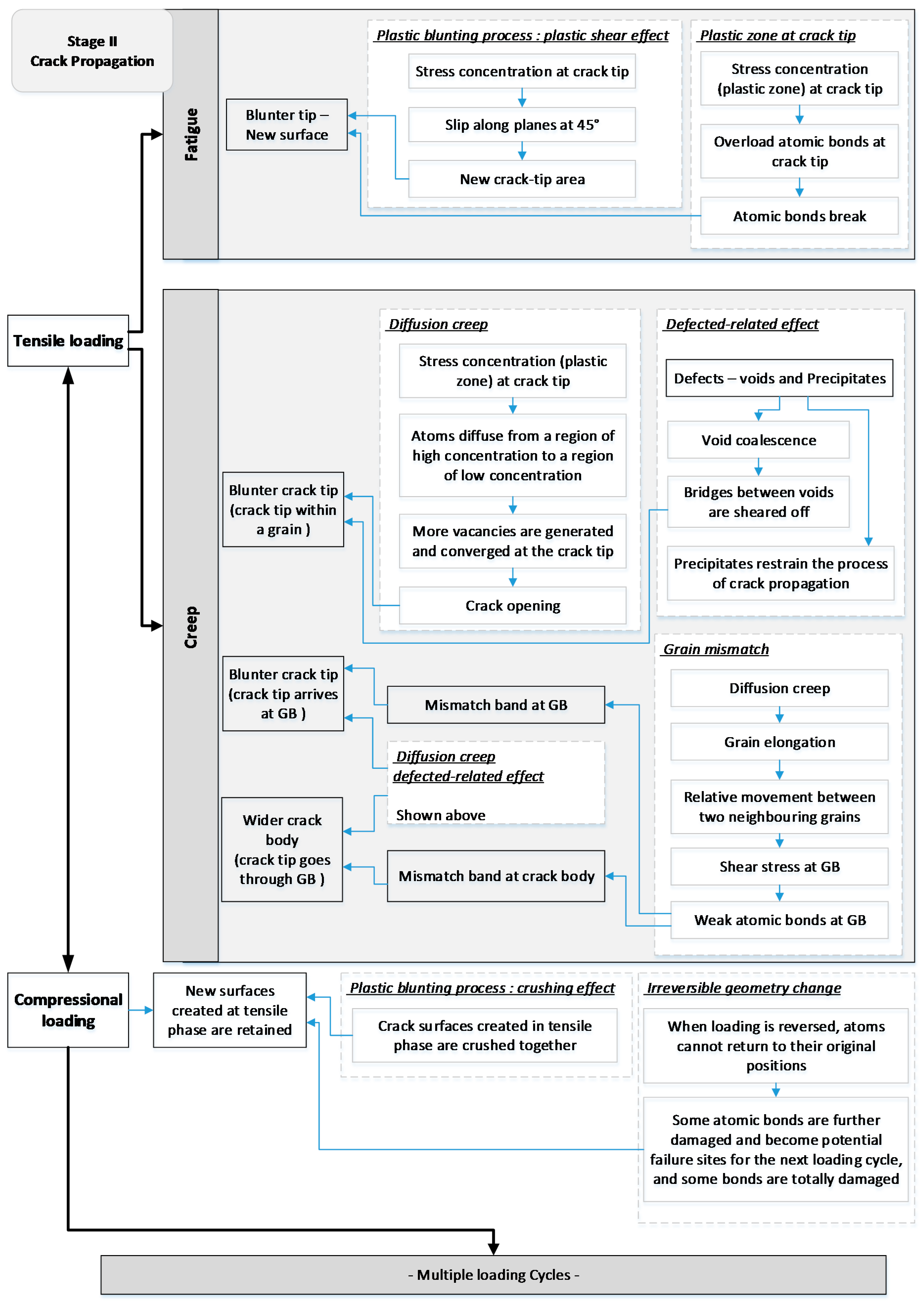
Numerical modelling and its experimental validation. This could be done at several levels. At a high level of abstraction, there are already formulations for describing the failure process. For example, Paris’s law [11] gives the crack growth in one cycle based on the stress intensity factor, the Arrhenius equation [63,64] presents the creep behaviour at the steady stage based on diffusion creep, and the conventional loading-life equations (the Basquin [65,66] equation and Coffin-Manson [67,68] equation) model life based on empirical data. At the level of detail providing in this paper, as represented in Figure 19 and Figure 20, the crack-growth process is graphically described in the microstructural level.
An ideal model would be one that represented the physics of the interactions between atoms within the finer level of the grain. Of interest are the interactions between the imperfections in the crystal lattice (e.g., dislocations), the grain boundaries, and the way the cracks propagate. However, this is likely to be a challenging proposition for some time. It would be ideal to observe the stages of crack growth using methods such as atomic force microscopy (AFM). Some work in this area includes the investigation of the force-distance relation and force field between two neighbouring bonds [59,60,61]. However, the difficulties are the extremely small area of examination afforded by AFM, and the practical difficulties of arranging a crack to grow in the sample. Furthermore, AFM measures free surfaces, whereas cracks have a three-dimensional interaction with the grains.
Possibly a more immediately achievable model could be to use finite element methods to represent the grains and grain boundary regions. It would be necessary to incorporate the anisotropy of the crystal lattice. This may be able to explore the interaction of the crack with the microstructure. Potentially this could be validated by microscopy. Neither observed fracture surfaces nor cross-sections show the full development of the crack architecture in the 3D volume. Also, fracture surfaces only show the Stage III development and termination of the cracks. A FEA approach might help better understand the evolution of the crack architecture across the Stages.
Our framework has proposed a number of variables, and the general direction of causality. If it were possible—which does not currently appear to be the case—to measure all these variables, then a statistical method such as factor analysis or structural path modelling might be used to determine the relative importance of the variables and the strength of the relationships.

6. Conclusions

Based on the general understanding of crack-growth behaviour, a microstructural conceptual framework has been proposed, and represented graphically, wherein fatigue and creep effects are treated separately due to the different damage principles. This microstructural model illustrates the process of damage accumulation from crack initiation to crack propagation then to structural failure. In particular, the analysis of crack propagation is mainly based on existing mechanisms of plastic blunting and diffusion creep. The possible grain-boundary behaviours, such as the mismatch behaviour at grain boundary due to creep deformation, are included. This conceptual framework is consistent with the various creep and fatigue microstructure observations in the literature, but goes further by integrating these premises and our proposed propositions together into a logically consistent framework that describes the overall failure process.

Author Contributions

D.L. and D.J.P. conceptualised the overall framework, D.L. worked out the details and produced the graphical model, D.L. and D.J.P. contributed to writing the paper.

Funding

This research received no external funding.

Conflicts of Interest

The authors declare no conflict of interest. The research was conducted without personal financial benefit from any funding body, and no such body influenced the execution of the work.

References

  1. June, W. A continuum damage mechanics model for low-cycle fatigue failure of metals. Eng. Fract. Mech. 1992, 41, 437–441. [Google Scholar] [CrossRef]
  2. Metzger, M.; Nieweg, B.; Schweizer, C.; Seifert, T. Lifetime prediction of cast iron materials under combined thermomechanical fatigue and high cycle fatigue loading using a mechanism-based model. Int. J. Fatigue 2013, 53, 58–66. [Google Scholar] [CrossRef]
  3. Seifert, T.; Riedel, H. Mechanism-based thermomechanical fatigue life prediction of cast iron. Part I: Models. Int. J. Fatigue 2010, 32, 1358–1367. [Google Scholar] [CrossRef]
  4. Jing, H.; Zhang, Y.; Xu, L.; Zhang, G.; Han, Y.; Wei, J. Low cycle fatigue behavior of a eutectic 80Au/20Sn solder alloy. Int. J. Fatigue 2015, 75, 100–107. [Google Scholar] [CrossRef]
  5. Shi, X.; Pang, H.; Zhou, W.; Wang, Z. Low cycle fatigue analysis of temperature and frequency effects in eutectic solder alloy. Int. J. Fatigue 2000, 22, 217–228. [Google Scholar] [CrossRef]
  6. Solomon, H. Fatigue of 60/40 solder. IEEE Trans. Compon. Hybrids Manuf. Technol. 1986, 9, 423–432. [Google Scholar] [CrossRef]
  7. Callister, W.D.; Rethwisch, D.G. Materials Science and Engineering; John Wiley & Sons: Hoboken, NJ, USA, 2011; Volume 5. [Google Scholar]
  8. Dowling, N.E. Mechanical Behavior of Materials: Engineering Methods for Deformation, Fracture, and Fatigue; Prentice: London, UK, 2012; p. 954. [Google Scholar]
  9. Evans, R.W.; Wilshire, B. Introduction to Creep; The Institute of Materials, University of Michiganb: Ann Arbor, MI, USA, 1993; p. 115. [Google Scholar]
  10. Kassner, M.E. Fundamentals of Creep in Metals and Alloys; Butterworth-Heinemann: Oxford, UK, 2015; p. 337. [Google Scholar]
  11. Paris, P.; Erdogan, F. A critical analysis of crack propagation laws. J. Basic Eng. 1963, 85, 528–533. [Google Scholar] [CrossRef]
  12. Liu, C.; Han, Y.; Yan, M.; Chaturvedi, M. Creep crack growth behaviour of alloy 718. Superalloys 1991, 178, 537–548. [Google Scholar]
  13. Sadananda, K. A theoretical model for creep crack growth. Metall. Mater. Trans. A 1978, 9, 635–641. [Google Scholar] [CrossRef]
  14. Cocks, A.; Pontern, A. Mechanics of Creep Brittle Materials 1; Springer Science & Business Media: Berlin/Heidelberg, Germany, 1989; p. 310. [Google Scholar]
  15. Ejaz, N.; Qureshi, I.; Rizvi, S. Creep failure of low pressure turbine blade of an aircraft engine. Eng. Fail. Anal. 2011, 18, 1407–1414. [Google Scholar] [CrossRef]
  16. Král, P.; Dvořák, J.; Kvapilová, M.; Svoboda, M.; Sklenička, V. Creep damage of Al and Al-Sc alloy processed by ecap. Acta Metall. Slov. Conf. 2013, 3, 136–144. [Google Scholar] [CrossRef]
  17. Dai, C.; Zhang, B.; Xu, J.; Zhang, G. On size effects on fatigue properties of metal foils at micrometer scales. Mater. Sci. Eng. A 2013, 575, 217–222. [Google Scholar] [CrossRef]
  18. Hanlon, T.; Kwon, Y.-N.; Suresh, S. Grain size effects on the fatigue response of nanocrystalline metals. Scr. Mater. 2003, 49, 675–680. [Google Scholar] [CrossRef]
  19. Laird, C. Mechanisms and theories of fatigue. Fatigue Microstruct. 1979, 149–203. [Google Scholar]
  20. Banks-Sills, L.; Motola, Y.; Shemesh, L. The m-integral for calculating intensity factors of an impermeable crack in a piezoelectric material. Eng. Fract. Mech. 2008, 75, 901–925. [Google Scholar] [CrossRef]
  21. Warzynek, P.; Carter, B.; Banks-Sills, L. The M-Integral for Computing Stress Intensity Factors in Generally Anisotropic Materials; National Aeronautics and Space Administration: Washington, DC, USA, 2005.
  22. Miller, K. Materials science perspective of metal fatigue resistance. Mater. Sci. Technol. 1993, 9, 453–462. [Google Scholar] [CrossRef]
  23. Rodopoulos, C.A. Fatigue damage map as a virtual tool for fatigue damage tolerance. In Virtual Testing and Predictive Modeling; Springer: Berlin/Heidelberg, Germany, 2009; pp. 73–104. [Google Scholar]
  24. Chowdhury, P.; Sehitoglu, H. Mechanisms of fatigue crack growth—A critical digest of theoretical developments. Fatigue Fract. Eng. Mater. Struct. 2016, 39, 652–674. [Google Scholar] [CrossRef]
  25. Laird, C. The influence of metallurgical structure on the mechanisms of fatigue crack propagation. In Fatigue Crack Propagation; ASTM International: West Conshohocken, PA, USA, 1967. [Google Scholar]
  26. Laird, C.; de La Veaux, R. Additional evidence for the plastic blunting process of fatigue crack propagation. Metall. Mater. Trans. A 1977, 8, 657–664. [Google Scholar] [CrossRef]
  27. Peralta, P.; Choi, S.-H.; Gee, J. Experimental quantification of the plastic blunting process for stage ii fatigue crack growth in one-phase metallic materials. Int. J. Plast. 2007, 23, 1763–1795. [Google Scholar] [CrossRef]
  28. Shi, K.; Cai, L.; Qi, S.; Bao, C. A prediction model for fatigue crack growth using effective cyclic plastic zone and low cycle fatigue properties. Eng. Fract. Mech. 2016, 158, 209–219. [Google Scholar] [CrossRef]
  29. Wang, G. The plasticity aspect of fatigue crack growth. Eng. Fract. Mech. 1993, 46, 909–930. [Google Scholar] [CrossRef]
  30. Weertman, J. Fatigue crack propagation theories. In Fatigue and Microstructure; American Society for Metals: Geauga County, OH, USA, 1979; Volume 279. [Google Scholar]
  31. Ham, R.; Broom, T. The mechanism of fatigue softening. Philos. Mag. 1962, 7, 95–103. [Google Scholar] [CrossRef]
  32. Zhai, T.; Jiang, X.; Li, J.; Garratt, M.; Bray, G. The grain boundary geometry for optimum resistance to growth of short fatigue cracks in high strength al-alloys. Int. J. Fatigue 2005, 27, 1202–1209. [Google Scholar] [CrossRef]
  33. Kinloch, A.; Wang, C.; Wu, S.; Ladani, R.; Zhang, J.; Bafekrpour, E.; Ghorbani, K.; Mouritz, A. Aligning Graphene Nanoplatelets with an External Electric Field to Improve Multifunctional Properties of Epoxy Nanocomposites. Carbon 2015, 94, 607–618. [Google Scholar] [CrossRef]
  34. Villechaise, P.; Cormier, J.; Billot, T.; Mendez, J. Mechanical behaviour and damage processes of udimet 720li: Influence of localized plasticity at grain boundaries. In Proceedings of the 12th International Symposium on Superalloys, Pennsylvania, PA, USA, 9–13 September 2012. [Google Scholar]
  35. Claude Bathias, A.P. Fatigue of Materials and Structures: Fundamentals; John Wiley & Sons: Hoboken, NJ, USA, 2013; p. 512. [Google Scholar]
  36. Sangid, M.D. The physics of fatigue crack initiation. Int. J. Fatigue 2013, 57, 58–72. [Google Scholar] [CrossRef]
  37. Wang, Z.; Beyerlein, I.; LeSar, R. Slip band formation and mobile dislocation density generation in high rate deformation of single fcc crystals. Philos. Mag. 2008, 88, 1321–1343. [Google Scholar] [CrossRef]
  38. Zerbst, U.; Vormwald, M.; Pippan, R.; Gänser, H.-P.; Sarrazin-Baudoux, C.; Madia, M. About the fatigue crack propagation threshold of metals as a design criterion—A review. Eng. Fract. Mech. 2016, 153, 190–243. [Google Scholar] [CrossRef]
  39. Margaritis, G.; Botsis, J. Energy evaluations during crack initiation. Eng. Fract. Mech. 1991, 40, 1123–1134. [Google Scholar] [CrossRef]
  40. Lach, R.; Adhikari, R.; Weidisch, R.; Huy, T.; Michler, G.; Grellmann, W.; Knoll, K. Crack toughness behavior of binary poly (styrene-butadiene) block copolymer blends. J. Mater. Sci. 2004, 39, 1283–1295. [Google Scholar] [CrossRef]
  41. Zerbst, U.; Klinger, C.; Clegg, R. Fracture mechanics as a tool in failure analysis—Prospects and limitations. Eng. Fail. Anal. 2015, 55, 376–410. [Google Scholar] [CrossRef]
  42. Fournier, D.; Pineau, A. Low cycle fatigue behavior of inconel 718 at 298 k and 823 k. Metall. Mater. Trans. A 1977, 8, 1095–1105. [Google Scholar] [CrossRef]
  43. Liu, D.; Pons, D.J. Physical-mechanism exploration of the low-cycle unified creep-fatigue formulation. Metals 2017, 7, 379. [Google Scholar]
  44. Liu, D.; Pons, D.; Wong, E.-h. The unified creep-fatigue equation for stainless steel 316. Metals 2016, 6, 219. [Google Scholar] [CrossRef]
  45. Pippan, R.; Grosinger, W. Fatigue crack closure: From lcf to small scale yielding. Int. J. Fatigue 2013, 46, 41–48. [Google Scholar] [CrossRef]
  46. Prasad, K.; Kumar, V.; Rao, K.B.S.; Sundararaman, M. A comparative assessment of crack closure mechanisms in timetal 834 near α titanium alloy under isothermal and thermomechanical fatigue loading. J. Alloys Compd. 2016, 688, 8–11. [Google Scholar] [CrossRef]
  47. Guo, Y.; Collins, D.; Tarleton, E.; Hofmann, F.; Tischler, J.; Liu, W.; Xu, R.; Wilkinson, A.; Britton, T. Measurements of stress fields near a grain boundary: Exploring blocked arrays of dislocations in 3d. Acta Mater. 2015, 96, 229–236. [Google Scholar] [CrossRef]
  48. McMurtrey, M.; Was, G.; Cui, B.; Robertson, I.; Smith, L.; Farkas, D. Strain localization at dislocation channel–grain boundary intersections in irradiated stainless steel. Int. J. Plast. 2014, 56, 219–231. [Google Scholar] [CrossRef]
  49. Pineau, A. Crossing grain boundaries in metals by slip bands, cleavage and fatigue cracks. Philos. Trans. R. Soc. A 2015, 373, 20140131. [Google Scholar] [CrossRef] [PubMed]
  50. Kumar, Y.; Venugopal, S.; Sasikala, G.; Albert, S.K.; Bhaduri, A. Study of creep crack growth in a modified 9cr–1mo steel weld metal and heat affected zone. Mater. Sci. Eng. A 2016, 655, 300–309. [Google Scholar] [CrossRef]
  51. Pretty, C.J.; Whitaker, M.T.; Williams, S.J. Thermo-mechanical fatigue crack growth of rr1000. Materials 2017, 10, 34. [Google Scholar] [CrossRef] [PubMed]
  52. Kacher, J.; Eftink, B.; Cui, B.; Robertson, I. Dislocation interactions with grain boundaries. Curr. Opin. Solid State Mater. Sci. 2014, 18, 227–243. [Google Scholar] [CrossRef]
  53. Benz, J.K.; Wright, R.N. Fatigue and Creep Crack Propagation Behaviour of Alloy 617 in the Annealed and Aged Conditions; Idaho National Laboratory (INL): Idaho Falls, ID, USA, 2013.
  54. Tang, Z.; Jing, H.; Xu, L.; Zhao, L.; Han, Y.; Xiao, B.; Zhang, Y.; Li, H. Creep-fatigue crack growth behavior of g115 steel under different hold time conditions. Int. J. Fatigue 2018, 116, 572–583. [Google Scholar] [CrossRef]
  55. Zhao, L.; Nikbin, K. Characterizing high temperature crack growth behaviour under mixed environmental, creep and fatigue conditions. Mater. Sci. Eng. A 2018, 728, 102–114. [Google Scholar] [CrossRef]
  56. Scheyvaerts, F.; Pardoen, T.; Onck, P. A new model for void coalescence by internal necking. Int. J. Damage Mech. 2010, 19, 95–126. [Google Scholar] [CrossRef] [Green Version]
  57. Xu, L.; Rong, J.; Zhao, L.; Jing, H.; Han, Y. Creep-fatigue crack growth behavior of g115 steel at 650 °C. Mater. Sci. Eng. A 2018, 726, 179–186. [Google Scholar] [CrossRef]
  58. Xu, L.; Zhao, L.; Han, Y.; Jing, H.; Gao, Z. Characterizing crack growth behavior and damage evolution in p92 steel under creep-fatigue conditions. Int. J. Mech. Sci. 2017, 134, 63–74. [Google Scholar] [CrossRef]
  59. Butt, H.-J.; Cappella, B.; Kappl, M. Force measurements with the atomic force microscope: Technique, interpretation and applications. Surf. Sci. Rep. 2005, 59, 1–152. [Google Scholar] [CrossRef] [Green Version]
  60. Neuman, K.C.; Nagy, A. Single-molecule force spectroscopy: Optical tweezers, magnetic tweezers and atomic force microscopy. Nat. Methods 2008, 5, 491–505. [Google Scholar] [CrossRef] [PubMed]
  61. Williams, J.M.; Han, T.; Beebe, T.P. Determination of single-bond forces from contact force variances in atomic force microscopy. Langmuir 1996, 12, 1291–1295. [Google Scholar] [CrossRef]
  62. Kato, M. Hall–petch relationship and dislocation model for deformation of ultrafine-grained and nanocrystalline metals. Mater. Trans. 2014, 55, 19–24. [Google Scholar] [CrossRef]
  63. Arrhenius, S. Über die dissociationswärme und den einfluss der temperatur auf den dissociationsgrad der elektrolyte. Zeitschrift Physikalische Chemie 1889, 4, 96–116. [Google Scholar] [CrossRef]
  64. Arrhenius, S. Über die reaktionsgeschwindigkeit bei der inversion von rohrzucker durch säuren. Zeitschrift Physikalische Chemie 1889, 4, 226–248. [Google Scholar] [CrossRef]
  65. Basquin, O. The exponential law of endurance tests. Am. Soc. Test. Mater. 1910, 10, 625–630. [Google Scholar]
  66. Wöhler, A. Theorie rechteckiger eiserner brückenbalken mit gitterwänden und mit blechwänden. Zeitschrift Bauwesen 1855, 5, 121–166. [Google Scholar]
  67. Coffin, L.F., Jr. A Study of the Effects of Cyclic Thermal Stresses on a Ductile Metal; Knolls Atomic Power Lab.: New York, NY, USA, 1953.
  68. Manson, S. Behavior of Materials Under Conditions of Thermal Stress. Available online: https://ntrs.nasa.gov/archive/nasa/casi.ntrs.nasa.gov/19930092197.pdf (accessed on 8 March 2018).
Figure 1. Three stages of crack growth.
Metals 08 00623 g001
Figure 2. Edge dislocation process.
Metals 08 00623 g002
Figure 3. Crack growth by diffusion mechanism.
Metals 08 00623 g003
Figure 4. Crack initiation due to dislocation.
Metals 08 00623 g004
Figure 5. Key elements (mechanisms) in the crack initial stage.
Metals 08 00623 g005
Figure 6. Stage I: Crack initiation.
Metals 08 00623 g006
Figure 7. Plastic blunting process.
Metals 08 00623 g007
Figure 8. Crack tip within a grain—Tensile loading.
Metals 08 00623 g008
Figure 9. Stress around crack tip.
Metals 08 00623 g009
Figure 10. Crack tip within a grain—Compressional loading.
Metals 08 00623 g010
Figure 11. Crack tip at grain boundary—Tensile loading.
Metals 08 00623 g011
Figure 12. Crack tip at grain boundary—Compressional loading.
Metals 08 00623 g012
Figure 13. Crack deflection.
Metals 08 00623 g013
Figure 14. Crack tip at triple point—Tensile loading.
Metals 08 00623 g014
Figure 15. Crack tip at triple point—Compressional loading.
Metals 08 00623 g015
Figure 16. Crack tip through grain boundary—Tensile loading.
Metals 08 00623 g016
Figure 17. Crack tip through grain boundary—Compressional loading.
Metals 08 00623 g017
Figure 18. Key elements for one loading cycle in the stage of crack for tension and compression.
Metals 08 00623 g018
Figure 19. Key elements for multiple load cycles in the stage of crack propagation.
Metals 08 00623 g019
Figure 20. Structural failure.
Metals 08 00623 g020
Figure 21. Key elements in the stage of structural failure.
Metals 08 00623 g021
Figure 22. Damage accumulation
Metals 08 00623 g022

