Abstract
A new process with argon injected into the ladle around the tapping hole for controlling slag carry-over in a teeming ladle was presented. Physical modeling was used to study the mechanism of controlling slag carry-over, and the feasibility of the new process was also investigated by industrial trials. The results show that vortex forms firstly, and then converts to drain sink. With argon injected into the ladle around the tapping hole, an argon ring was formed, and the rotating angular velocity of the melt close to the tapping hole reduced dramatically, and even vanished when the melt passed the argon ring. Therefore, the new controlling slag carry-over process can eliminate the slag carry-over caused by vortex. The velocity of the melt toward the tapping hole was reduced due to the bubble buoyancy as the melt passed the argon ring. So, the new process can decrease the critical height of slag carry-over caused by drain sink. The application feasibility of the new controlling slag carry-over process is verified by the plant trials. Compared to the traditional teeming ladle process, the new controlling slag carry-over process shows much better efficiency on decreasing the steel residual in the poured ladle.
1. Introduction
During the continuous casting process, molten steel covered by a slag layer is poured from the ladle to the tundish through a nozzle located in an eccentric position in the ladle floor. During the ladle teeming process, slag carry-over from ladle to tundish not only decreases the heats of continuous casting due to the slag accumulation in the tundish, but also worsens the steel cleanness [1,2,3]. Moreover, to maximize metallic yield and reduce costs, the steel residual is highly desirable to be as small as possible. Therefore, for the sake of cleaner steel, improved yield, and higher production, the onset of slag carry-over should be stalled as long as possible during ladle teeming. According to the literature [1,2,3,4,5], two different mechanisms can lead to slag carry-over in teeming ladle: vortex or drain sink. Vortex is characterized by high tangential velocities in the neighborhood of the tapping hole, and can develop even with a high bath height of steel in the teeming ladle. Although simple in principle, the formation of vortex in the teeming ladle is not as easy to understand as is the vortex formed in a bath tube draining water. Hammerschmid et al. [1] and Andrzejewski et al. [6] reported that the vortex formation depends strongly on the state of initial rotation. However, Morales et al. [7] and Dubke et al. [8] reported that the initial rotation had little or null influence on the vortex formation. The vortex formation is also affected by the eccentricity of the draining nozzle [1,4,9,10], the steel throughput [5,11], the slag thickness [12,13], the ratios of viscosity as well as density between steel and slag [14], the diameter ratio of the outlet nozzle and the ladle [2,15], and so on. On the other hand, a drain sink is characterized by the radial flow and develops in the last stage of the teeming process, when less liquid steel is left in the ladle. A drain sink is always present at the end of the process and takes place when the bath height of the steel is approximately equal to the nozzle diameter [4,6,16]. Several researchers claim that there was no vortex formation and slag carry-over was caused by drain sink in the teeming ladle [4,8], while more researchers reported that vortex was formed prior to the drain sink formation [1,2,3,7,17].
Once a slag flow is detected by magnetic fields [18,19], vibration signals [20,21], or ultrasonic sensors [22], slag carry-over can be controlled by closing the gate. However, all of those slag control systems can only detect rather than suppress the slag carry-over caused by vortex and drain sink. With the help of slag control systems, the slag carry-over can be stopped as long as possible, but the amount of residual steel will be still considerably high, decreasing the metallic yield. Thus, how to minimize the slag carry-over during ladle teeming economically is still one of the problems during the production of clean steel.
Gas injection is commonly practiced in the secondary metallurgy processes and continuous casting for the homogenization of composition and temperature, inclusion removal, and the prevention of nozzle clogging. In the present work, a new controlling slag carry-over process with argon injected into the ladle around the tapping hole during ladle teeming is presented, as shown in Figure 1. This is to say, argon is injected into the ladle via an annular porous plug located around the tapping hole in the ladle floor in the teeming ladle. Then, an argon ring is formed, so the rotating melt flow close to the tapping hole may be restrained, resulting in the suppression of the vortex. Moreover, the radial melt flow toward the tapping hole may be also weakened, which restrains the drain sink. Therefore, the new process, which is well controlled, may be helpful to diminish the slag carry-over caused by the vortex and drain sink. A physical model was established to study the mechanism of controlling the slag carry-over of the new process, and the effects of the operation parameters on controlling slag carry-over under the new process were also investigated. Furthermore, the feasibility of the new process was also investigated by industrial trials.
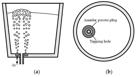
Figure 1.
Schematic of the new controlling slag carry-over process with argon injected into the ladle around the tapping hole: (a) front view; and (b) top view.
2. Experimental
Based on the principle of geometrical similarity, a 1:5 downscale physical model that simulated the ladle with argon injected around the tapping hole was made. Water and air were chosen to simulate the molten steel and argon gas in an actual system, respectively. According to the similarity rule, in the system of a ladle with gas blowing, a physical model should have the same modified Froude number as the prototype [23]. Therefore, the relations between model and prototype for gas flow rates can be expressed as follows:
where λ is the model geometrical scale factor, and Qm and Qp are the gas flowrates of the model and the prototype, respectively. The main parameters for the model and the prototype are listed in Table 1. To model the metal/slag behavior, a mixture of kerosene and vacuum pump oil was used as the model slag, and the proportion of them satisfied the principle that the kinematic viscosity ratio of the mixture oil to water equals that of slag to liquid steel [24].

Table 1.
Main parameters for model and prototype.
The schematic diagram of the experimental setup is shown in Figure 2, and Figure 3 shows the annular porous plug that was used in the physical model. The model was made of Perspex, and the ball valve 9, which was installed at the end of the model ladle nozzle, had an inner diameter of 20 mm (larger than the inner diameter of 18 mm of the model ladle nozzle) to avoid any effect of the ball valve on the flow in the model ladle nozzle. The experimental apparatus consisted of a water supply system, a gas supply system, and a video system. All of the important experimental phenomena were recorded by a digital camera. The detailed procedures for the experiments are as follows:

Figure 2.
Schematic of the experimental setup: 1. air compressor; 2. pressure gauge; 3. air tank; 4. spring safety valve; 5. gas pressure regulator; 6. gas flow controller; 7. annular porous plug; 8. beaker; 9. ball valve; 10. model ladle; 11. fluid flowmeter; and 12. digital camera.

Figure 3.
Annular porous plug used in the physical model.
First, during the continuous casting ladle teeming process, both the mechanism of slag carry-over without gas blowing and the mechanism of controlling slag carry-over of the new process with argon bubbling were investigated by observation, and the processes of slag carry-over and controlling slag carry-over were all recorded using a digital video camera. Commercial software was used so that the video could be played frame by frame. The frames showing slag carry-over as well as control of slag carry-over were found, saved in pictures by the player software, and the time interval between the adjacent frames was recorded and determined.
Then, the metal/slag interface behavior under the new process was studied. The metal/slag interface phenomenon that occurred in the model was observed by the naked eye and recorded by the digital camera under different operation parameters. In this way, the critical operation parameters of the metal/slag interface behavior can be determined and recorded. Each process was normally repeated three times.
Finally, the effects of operation parameters on controlling the slag carry-over under the new process were investigated. As shown in Figure 2, during the model ladle teeming process, when the bath with typical slag thickness fell from the working ladle depth to a certain height, air was blown into the model ladle. Once the slag carry-over occurred (or just several seconds after occurrence of slag carry-over), the teeming process would be stopped by closing the ball valve 9. The mixture of model slag and water solution was then collected under a certain bath height (gained by measuring the leaving bath height in the model ladle). Dealing with the collected mixture, the pure model slag can be separated. The slag carry-over rate at a certain bath height can be given by the following equations:
where ηh is the slag carry-over rate at the bath height of h, and V0 and Vh are the initial model slag volume in the model ladle and the carry-over slag volume at the bath height of h, respectively.The slag carry-over rate can reflect the degree of slag carry-over under different bath heights. According to the quantitative analysis of slag carry-over rate, the effect of gas flow rate on controlling slag carry-over under typical slag thickness was investigated.
3. Results and Discussion
3.1. Behavior of Slag Carry-over during the Ladle Teeming Process
Figure 4 shows the behavior of slag carry-over caused by vortex and drain sink during the continuous casting ladle teeming process from a physical model. It can be seen that vortex forms firstly and then converts to drain sink. That is to say, during the formation of vortex, a dimple formed at the beginning (photograph 0.0 s); then, a vortex with a short vibrating tail formed (photograph 0.4 s), and the vortex extended its tail toward the nozzle quickly (photographs 0.4–0.468 s). Once the vibrating tail comes to the nozzle at the model ladle floor, it becomes a steadily and fully developed vortex with a non-vibrating tail formed (photograph 0.535 s). As teeming continues, the stable vortex causes slag carry-over continuously (photographs 0.535–1.001 s). When the bath height comes to a certain height, the stable vortex begins converting to drain sink (photograph 1.269 s), and is replaced by a drain sink gradually (photographs 1.269–1.468 s). At last, a fully developed drain sink forms (photograph 1.602 s) and becomes stronger and stronger (photographs 1.602–2.470 s).

Figure 4.
Behavior of slag carry-overcaused by vortex and drain sink from a physical model.
It can also be seen from Figure 4 that the critical bath height for fully developed vortex formation is 26.0 mm (photograph 0.535 s), while it is 23.5 mm for drain sink formation (photograph 1.602 s).
3.2. Behavior of Controlling Slag Carry-over of the New Process
The behavior of controlling slag carry-over of the new process with argon injected into the ladle around the tapping hole is shown in Figure 5. It can be seen that there is no vortex formation, which means that the slag carry-over caused by vortex can be eliminated by the new process. Furthermore, the critical bath height for drain sink formation is 20.5 mm under the new process (Figure 5d), while it is 23.5 mm before argon blowing. Although the slag carry-over caused by a drain sink cannot be eliminated by the new process, it can be suppressed obviously.
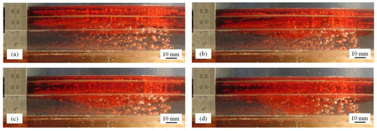
Figure 5.
Behavior of controlling slag carry-over of the new process with argon injected into the ladle around the tapping hole at bath heights: (a) 26 mm, (b) 23 mm, (c) 21.5 mm, and (d) 20.5 mm.
After argon was injected into the ladle around the tapping hole, the flow behavior during the ladle teeming process changed, resulting in the behavior variations of vortex and drain sink. That is to say, the rotating angular velocity of the melt in the ladle close to the tapping hole is responsible for the formation of a vortex. With argon injected into ladle around the tapping hole, an argon ring is formed, and the rotating angular velocity of the melt close to the tapping hole can be reduced dramatically, and even vanished, when the melt is passing through the argon ring. Therefore, the vortex is eliminated and the slag carry-over caused by vortex is also avoided. When the flow volume toward the draining nozzle is smaller than the outflow capacity of the nozzle, the drain sink is formed. With argon blowing, the velocity of the radial melt flow toward the tapping hole is reduced due to the bubble buoyancy as the melt is passing through the argon ring, decreasing the outflow capacity of the nozzle. So, the critical bath height for drain sink formation is lowered, restraining the slag carry-over caused by drain sink.
3.3. Metal/Slag Interface Behavior under the New Process
By direct observation with the naked eye in a water model, the slag thickness has a big effect on the metal/slag interface behavior during the ladle teeming process. This is to say, as the slag thickness is smaller than 20 mm, the bubbles can pass through the slag layer under smaller gas flowrates, and slag eyes are formed over the nozzle under bigger gas flowrates. With those slag thicknesses larger than 20 mm, unreasonable argon blowing can cause foam slag beneath the slag layer, as shown in Figure 6. Under the thick slag, some bubbles reaching the metal/slag interface cannot pass through the slag layer, and some of them are surrounded by a little slag due to the bubbles’ attack to the interface. More and more bubbles with/without slag gather (including the growth of some bubbles) beneath the slag layer and form the foam slag. From the water model, once foam slag beneath the slag layer forms, the slag carry-over easily occurs in the high bath height. Therefore, it is necessary to control the operation parameters in the new process to avoid the formation of the foam slag. For the present study, under the slag thickness of 24 mm, those gas flowrates smaller than 0.75 NL/min can avoid the foam slag.

Figure 6.
Behavior of foam slag beneath the slag layer under the slag thickness of 24 mm.
3.4. Effects of Operation Parameters on Controlling the Slag Carry-over under the New Process
The variation of slag carry-over rate with bath height under various gas flow rates at typical slag thicknesses is shown in Figure 7. As mentioned above, under the slag thickness of 24 mm, the maximum gas flow rate for avoiding foam slag is 0.75 NL/min, so those gas flow rates smaller than that were investigated as shown in Figure 7b. It can be seen that under the thin slag, the quantity of slag carry-over during the ladle teeming process decreases with the increase of gas flowrate, and large gas flowrates show good efficiency on controlling the slag carry-over. Meanwhile, the gas flow rates that are smaller than the maximum one for avoiding foam slag have a small effect on the slag carry-over under the thick slag. On the whole, the new process with reasonable operation parameters can obviously decrease the slag carry-over during the ladle teeming process.

Figure 7.
The variation of slag carry-over rate with bath height under various gas flow rates at the slag thickness of (a) 10 mm and (b) 24 mm.
4. Trial Application
To evaluate the effect of the controlling slag carry-over of the new process, plant trials were carried out in the 110 ton LF (Ladle Furnace) of the CSP (Compact Strip Production) thin slab continuous casting line in an Iron & Steel Company in China. It is quite difficult to produce an annular porous plug with an inner diameter more than 400 mm that is located around the tapping hole of the ladle in a steel plant. The installation, cost, and lifetime were also taken into account. So, the porous plug used in the new process was integrated with the ladle nozzle well block, and four porous plugs were mounted on the conventional ladle nozzle well block, as shown in Figure 8a. Figure 8b shows the installation of the porous plug of the new process in the ladle of the steel plant.

Figure 8.
The porous plug of the new process integrated with the ladle nozzle well block: (a) the configuration; and (b) the installation in the ladle of a steel plant.
Then, 55 heats was investigated in the plant trials, and the comparison of the steel residual during the ladle teeming process between the original and new controlling slag carry-over process is shown in Table 2. Figure 9 shows the typical steel residual of one heat in the ladle that just finished the casting under the two processes. It can be seen that, compared with the original process, the steel residual reduces by 40% with the new controlling slag carry-over process. Therefore, the new controlling slag carry-over process shows good efficiency in decreasing the steel residual in the poured ladle.
Table 2.
Comparison of the steel residual during the ladle teeming process between the original and new controlling slag carry-over process.

Figure 9.
The typical steel residual of one heat in the ladle just finished the casting: (a) the original process; and (b) the new controlling slag carry-over process.
5. Conclusions
A physical model was established to study a new controlling slag carry-over process with argon injected into the ladle around the tapping hole during ladle teeming. The feasibility of the new process was also investigated by industrial trials. The main conclusions could be summarized as follows:
- (1)
- During a continuous casting ladle teeming process, vortex is derived from the dimple at the water/oil interface and quickly develops from the one with a short vibrating tail to a fully developed vortex with a non-vibrating tail. As teeming continues to a certain bath height, the stable vortex begins converting to drain sink gradually. Finally, a fully developed drain sink forms and becomes stronger and stronger. The critical bath heights for the formation of a fully developed vortex and drain sink in a water model are 26.0 mm and 23.5 mm, respectively.
- (2)
- By the new process with argon injected into the ladle around the tapping hole, an argon ring is formed, and the rotating angular velocity of the melt close to the tapping hole can be reduced dramatically, and even vanished, when the melt is passing through the argon ring. Therefore, the slag carry-over caused by vortex can be eliminated. With argon blowing, the velocity of the radial melt flow toward the tapping hole is reduced due to the bubble buoyancy as the melt is passing through the argon ring, decreasing the outflow capacity of the nozzle. Then, the critical bath height for drain sink formation is lowered. So, the slag carry-over caused by drain sink can be suppressed, obviously.
- (3)
- As the model slag thickness is smaller than 20 mm, the bubbles can pass through the slag layer under smaller gas flow rates, and slag eyes are formed over the nozzle under bigger gas flow rates. Under those model slags with thicknesses larger than 20 mm, unreasonable argon blowing can cause foam slag beneath the slag layer, resulting in the slag carry-over in the high bath height.
- (4)
- Under the thin slag, the quantity of slag carry-over during the ladle teeming process decreases with the increase of gas flow rate, and large gas flow rates show good efficiency on controlling the slag carry-over. When the gas flow rates are smaller than the maximum one for avoiding foam slag, they have a small effect on the slag carry-over under the thick slag.
- (5)
- By the plant trials, compared with the original process, the steel residual reduces by 40% with the new controlling slag carry-over process. Therefore, the new controlling slag carry-over process show good efficiency on decreasing the steel residual in the poured ladle.
Author Contributions
Experiment, S.Z. and M.Z.; Formal Analysis, S.Z.; Resources, S.Z.; Writing-Original Draft Preparation, S.Z.; Writing-Review & Editing, M.Z.; Project Administration, S.Z. and M.Z.; Funding Acquisition, S.Z.
Funding
This research is supported by the National Natural Science Foundation of China (No. 51474059, No. 51774077, No. 51204042).
Acknowledgments
We wish to thank Bikai Qiao for his help of doing the experiment.
Conflicts of Interest
The authors declare no conflict of interest.
References
- Hammerschmid, P.; Tacke, K.H.; Popper, H.; Weber, L.; Dubke, M.; Schwerdtfeger, K. Vortex formation during drainage of metallurgical vessels. Ironmak. Steelmak. 1984, 11, 332–339. [Google Scholar]
- Sankaranarayanan, R.; Guthrie, R.I.L. Slag entraining vortexing funnel formation during ladle teeming: Similarity criteria and scale-up relationships. Ironmak. Steelmak. 2002, 29, 147–153. [Google Scholar] [CrossRef]
- Davila, O.; Garcia-Demedices, L.; Morales, R.D. Mathematical simulation of fluid dynamics during steel draining operations from a ladle. Metall. Mater. Trans. B 2006, 37, 71–87. [Google Scholar] [CrossRef]
- Mazzaferro, G.M.; Piva, M.; Ferro, S.P.; Bissio, P.; Lglesias, M.; Calvo, A.; Goldschmit, M.B. Experimental and numerical analysis of ladle teeming process. Ironmak. Steelmak. 2004, 31, 503–508. [Google Scholar] [CrossRef]
- Koria, S.C.; Kanth, U. Model studies of slag carry-over during drainage of metallurgical vessels. Steel Res. Int. 1994, 65, 8–14. [Google Scholar] [CrossRef]
- Andrzejewski, P.; Diener, A.; Pluschkell, W. Model investigations of slag flow during last stages of ladle teeming. Steel Res. Int. 1987, 58, 547–552. [Google Scholar] [CrossRef]
- Morales, R.D.; Dávila-Maldonado, O.; Calderón, I.; Morales-Higa, K. Physical and mathematical models of vortex flows during the last stages of steel draining operations from a ladle. ISIJ Int. 2013, 53, 782–791. [Google Scholar] [CrossRef]
- Dubke, M.; Schwerdtfeger, K. Phenomena occurring during drainage of metallurgical vessels. Effect of stopper rod on vortex formation and development of surface waves. Ironmak. Steelmak. 1990, 17, 184–192. [Google Scholar]
- Sucker, D.; Reinecke, J.; Hage-Jewainski, H. Evaluation of melting behaviour of slags containing nonferrous metals. Stahl. Eisen. 1985, 105, 765–769. [Google Scholar]
- Lin, R.; Yan, Z.G.; Yu, J.K. Physical modeling test of vortex during teeming from ladle. J. Northeast. Univ. 2010, 31, 1287–1291. [Google Scholar]
- Zhou, L.; Cao, C.H.; Dai, W.; He, X. Physical simulation of sink-vortex slag entrainment in 120 t ladle. Steelmaking 2012, 28, 56–59. [Google Scholar]
- Huang, Y.; Ye, S.F.; Tao, Y.P.; Li, M.M.; Huang, Z.M. Influence of slag thickness and outlet shape on the vortex sink carrying slag. J. Iron Steel Res. 1995, 7, 9–14. [Google Scholar]
- Lin, R.; Yan, Z.G.; Liu, T.; Yu, J.K. Modeling formation mechanism of vortex during steel casting in a 60 t ladle. Chin. J. Process Eng. 2010, 10, 655–659. [Google Scholar]
- Hassall, G.J.; Jackaman, D.P.; Hawkins, R.J. Phosphorus and sulphur removal from liquid steel in ladle steelmaking processes. Ironmak. Steelmak. 1991, 18, 359–369. [Google Scholar]
- Sankaranarayanan, R.; Guthrie, R.I.L. A laboratory study of slag entrainment during the emptying of metallurgical vessels. In Proceedings of the Steelmaking Conference, Toronto, Canada, 5–8 April 1992; pp. 655–664. [Google Scholar]
- Kojola, N.; Takagi, S.; Yokoya, S.; Jönsson, P. Prediction and disarming of drain sink formation during unsteady-state bottom teeming. ISIJ Int. 2009, 49, 1–9. [Google Scholar] [CrossRef]
- Huang, Y.; Ye, S.F.; Li, M.M. Technology of preventing slag carry-over during casting process. Steelmaking 1996, 12, 26–31. [Google Scholar]
- Idstein, D.J.; Hoffman, J.P.; Witek, E.T.; Hogan, J.L. Development of an improved ladle nozzle system. Iron Steelmak. 1994, 21, 79–81. [Google Scholar]
- Qiu, D.M. A novel continuous casting slag detection system using a single-coil sensor. Scand. J. Metall. 1997, 26, 178–182. [Google Scholar]
- Tan, D.P.; Li, P.Y.; Pan, X.H. Application of improved HMM algorithm in slag detection system. J. Iron Steel Res. Int. 2009, 16, 1–6. [Google Scholar] [CrossRef]
- Trotter, D.J.; Duncan, G.; Camplin, J.M. Development of a ladle/tundish slag detector. Iron Steelmak. 1991, 18, 57–60. [Google Scholar]
- Walker, D.I.; Dawson, S.; Mountford, N.D.G.; Sommerville, I.D.; Mclean, A. Development of ultrasonic sensors for the early detection of slag carryover. Iron Steelmak. 1990, 17, 59–64. [Google Scholar]
- Zhu, M.Y.; Xiao, Z.Q. Maths-Physical Modeling of Steel Refining Process, 1st ed.; Metallurgical Industry Press: Beijing, China, 1998; pp. 124–125. [Google Scholar]
- Zheng, S.G.; Zhu, M.Y. Physical modelling of inclusion behavior in secondary refining with argon blowing. Steel Res. Int. 2008, 79, 685–690. [Google Scholar] [CrossRef]
© 2018 by the authors. Licensee MDPI, Basel, Switzerland. This article is an open access article distributed under the terms and conditions of the Creative Commons Attribution (CC BY) license (http://creativecommons.org/licenses/by/4.0/).