Profile Map of Weld Beads and Its Formation Mechanism in Gas Metal Arc Welding


School of Mechanical and Automotive Engineering, South China University of Technology, Guangzhou 510641, China
*
Author to whom correspondence should be addressed.
Metals 2019, 9(2), 146; https://doi.org/10.3390/met9020146
Submission received: 19 December 2018
/
Revised: 26 January 2019
/
Accepted: 27 January 2019
/
Published: 29 January 2019
Abstract
:In order to investigate the profile map of weld beads and its formation mechanism in gas metal arc welding (GMAW), bead-on-plate welding was carried out with different average currents, and the dimensions of a weld bead were measured. The results show that the profile of weld beads can be divided into three stages according to the volume relationship between the melted filler metal and the weld pool. During the stages, the top surface of the reinforcement consisting of the central plane and the side plane mainly goes through inversed-U, W, V, and U shapes, which are mainly attributed to the change of flow pattern. Moreover, the role played by the bottom wall in determining the flow pattern and the resultant bead profile has been investigated as well. The experiment results show that with the bottom wall changing from the solid to the totally melted state, the role of redirecting, redistributing and bearing the molten metal played by the bottom wall gradually disappears. As a result, the side reinforcement is no longer covered by the liquid flowing backward. The top reinforcement is thoroughly collapsed when the width of the bottom reinforcement exceeds that of the top one by 1.1 mm.
1. Introduction
Gas metal arc welding (GMAW) is a metal joining process in which droplets are melted at the tip of electrode then transferred to a weld pool and solidified to form a bead on the base metal [1]. The mechanical properties of a weld bead are significantly affected by its profile, which mainly comprises depth of penetration, bead width, reinforcement height, and contact angle, etc. The formation of a bead profile in GMAW is complicated because of the involvement of droplets [2], which has motivated many researchers to study the bead formation in detail.
Meng et al. [3] studied the formation mechanism of humping defects in GMAW, which provides useful knowledge about the reinforcement formation, but the humping has a periodic undulate profile, which differs from the ordinary bead appearance. Furthermore, the momentum of the backward flow metal is the direct reason for the humping bead formation by capturing the tracer particle movement simultaneously [4]. However, the experiment was carried out with the base metal not fully penetrated. A fully penetrated bead is needed in fabricating metal parts. In regard to the fully penetrated beads, Liu et al. [5] studied the stabilization of the weld pool through jet flow argon gas backing, but they did not point out how the jet flow argon affects the bead profile. Moreover, the high crown in a fully penetrated Mg butt joint weld can be reduced by deepening the groove in the backing plate [6]. Unfortunately, they did not explore the mechanism of how the backing plate affects the reinforcement. Furthermore, the current literature related to the bead profile sets the welding current in a narrow range to achieve either a partially penetrated bead or a fully penetrated one instead of a wide range to achieve beads ranging from a shallow penetration to a collapsed profile, which hinders a more comprehensive understanding of the whole stages of forming a weld bead.
Pang et al. [7] pointed out that the formation of a weld bead in the GMAW process is closely associated with the heat input and the weld pool behavior, which was studied by many researchers. Wang et al. [4] demonstrated that during the welding process, the surface of a weld pool is significantly depressed under the combined effects of droplet impingement and the arc pressure, which leaves a thin liquid pool area between the arc and the base metal. The thin liquid pool and the droplet impingement plays a significant role in determining the flow pattern in the weld pool. When the accelerated droplet impinges into the thin weld pool, the liquid in the weld pool is driven downward to the bottom and redirected to the tail where the molten metal solidifies to form a bead [8,9]. Regarding the role played by droplet impingement in the reinforcement formation, Chen et al. [10] compared the difference in bead profile by simulating the process with and without the droplet impingement, and results showed that the reinforcement is higher when there is droplet impingement. Moreover, the profile of a weld bead is also impacted by the direction of droplet impingement. Zhang et al. [11] reported that the center lines of the lower part and the upper portion no longer coincides once the welding torch is inclined. Although the molten behavior has been studied quite adequately by the mentioned researches, all the weld pool walls involved above are almost in their solid state, and the role played by the wall in affecting the flow pattern and the resultant bead profile is rarely reported.
The present study investigated the various profiles of weld beads by setting the welding current to a wide range. The objectives were as follows: (1) Map and divide into stages the profile of weld beads; (2) reveal the formation mechanism of a weld bead and figure out the role that the wall of a weld pool plays in the profile formation process.
2. Materials and Methods
Bead-on-plate welding experiments were conducted on aluminum alloy AA6061 base metal (250 × 60 × 3 mm3) using ER4043 filler wire. A schematic of the experimental setup for GMAW is given in Figure 1a. The chemical compositions of AA6061 alloys and ER4043 are provided in Table 1. Because of the low energy input for thin sheets, the Pulsed-GMAW (P-GMAW) process was employed, and the parameters are presented in Table 2. The average current, labelled as current A/B/C/D/E and ranging from 72 A to 136 A, was obtained by changing the base current from 30 A to 110 A while the peak current was kept constant at 280 A as shown in Figure 1b. Pure argon was coaxially supplied as a shielding gas at a flow rate of 18 L/min. For each process setting, three samples which are at least 15 cm were welded, and those with the best typical appearances were chosen as the research object. After welding, the specimens were cut along the transverse cross-sections of the welds. The samples were ground and polished with colloidal silica and were subsequently etched for metallographic analysis using the standard Keller’s agent for 20 s. Then, the profiles of the cross section were observed using the LIOO SZ850T microscope (Beijing-Jinghao Co. Ltd., Beijing, China) and the dimensions were measured using the included software.
3. Results and Discussion
3.1. Profile Map and Stages of Weld Beads
Figure 2 shows the map of weld beads, which displays clearly that with the increase of mean current, the profile can be divided into three stages according to the volume relationship between the melted filler metal and the weld pool: the melted filler metal (i) overflowing (Figure 2a), (ii) matching (Figure 2b–d), and (iii) inadequate (Figure 2e) for the weld pool when the average current is at a low, medium, and high level, respectively. In our cases, when the average current is smaller than 88 A, although the heat input is low for both the filler wire and the base metal, the melted volume of filler metal is significantly excessive for that of the base metal which composes the weld pool, thus leading to a volume lack for the weld pool to accommodate the excessive melted filler metal. As a result, the excess filler metal overflows the weld pool and spreads onto the surface of the solid base metal. Hence, as shown by the green lines in Figure 2a, the typical profile characteristic in this stage is the excess within the maximum width of deposited filler metal on the base metal over that of the weld pool. Furthermore, under the combined effect of poor wettability resulting from a small welding current [12] and surface tension, a smaller contact angle of 114.5° will be formed after the molten wire spreads and accumulates on the surface of the base metal, as represented by Figure 2f,g. The smaller the welding current, the greater the volume deviation of the melted wire over the melted base metal, and thus the greater volume of the overflowing melted wire, which leads to a greater width deviation between the reinforcement and the weld pool. An example for this viewpoint is the bead welded by cold metal transfer (CMT) + pulse process [7], which is characterized by a significant width deviation: The maximum width of reinforcement is 219% of that of the weld pool and the contact angle is only 26.8 degrees, as can be seen from Figure 2h. Another example is the bead welded by tungsten inert gas welding (TIG) + CMT hybrid welding [12] in which the maximum width of reinforcement is also double that of the weld pool and the contact angle is nearly 90°.
The width difference between reinforcement and weld pool decreases gradually with increasing average current and finally diminishes when the current is up to 120 A. Although the heat input grows with the increase of average welding current and a larger volume is melted for both filler wire and base metal [13], the diminished width difference, however, indicates that the base metal has a higher melting rate than the filler wire. As we can see from Figure 3a, when the current increases from 72 A to 136 A, the increased melted area for filler wire and base metal are 12.82 mm2 and 28.05 mm2. Thus, with the weld pool gaining a larger room at a higher speed than the melted speed for filler wire, its capacity to accommodate the melted filler wire grows, which results in a gradual decrease in volume difference between the melted filler wire and the base metal. The decreased volume difference makes most of the melted filler wire held by the growing weld pool, thus leaving less melted filler wire overflowing the weld pool. Hence, less melted filler wire spreads and accumulates outside the weld pool on the base metal, which, as a result, displays the diminished width difference. The difference in width will decrease further with the increasing current and finally disappears when the average current is up to the critical value of 120 A, and it will not emerge once the average current is beyond the critical value. Namely, although melted filler wire accumulation on the beads remains, the width of the reinforcement is equal to that of the weld pool. However, because of the weakened accumulation, the height decreases and the contact angle increases accordingly, as shown by Figure 2g and Figure 3b. Therefore, with filler metal accumulated on the base metal, beads at this stage are characterized by the matched width between the reinforcement and the weld pool.
With the average current increasing further, more heat is brought to melt the base metal, and then more liquid is produced and held by the weld pool. Meanwhile, the driving force and the arc pressure is also strengthened owing to the higher current, which propels the liquid in the weld pool to flow upwards and outwards, creating a thin liquid film between the arc and solid base metal [14,15]. Thus, the heat brought by the arc can be more easily transferred to the base metal in a solid state, which will be melted faster. Moreover, Wang et al. [16] indicated that droplets with abundant heat would impinge into the weld pool at high speed, which will easily pass through the thin liquid layer, crash against the solid bottom, and create a crater. The penetration is then deepened further, and when the average current reaches 104 A, the base metal is fully penetrated.
If the average current continues to grow, reinforcement then will become flat or even sunken due to the greater heat input and the combined effect of all kinds of driving forces exerted on the weld pool [7]. With the base metal fully penetrated, the bottom wall of a weld pool is no longer in its solid state and it is in delicate balance between the surface tension of liquid bottom and the driving forces acted on weld pool. Because the confining effect provided by the bottom wall is significantly weakened due to the transition of the bottom wall from a solid state to liquid metal, the flow pattern of liquid metal in the weld pool changes. Although the flowing molten metal has the ability to scour out or “dig” a channel with its thermal energy and momentum, the flow pattern is determined not only by the “digging” ability but also by the confining effect the weld pool wall can provide. Thus, when the bottom wall is in a solid state, it can provide a strong confining effect to force the liquid metal to flow along the channel which consists of a solid wall. For example, the formation mechanism of bead hump in high-speed GMAW is ascribed to the redirecting role provided by the sloping leading edge of the weld pool [17]. In our case, when the bottom wall is in a solid state, it can resist the digging from thermal liquid and redirect the liquid backward. The backward liquid then accumulates and solidifies at the rear of the weld pool to form reinforcements. However, when the base metal is fully melted and penetrated, the surface tension provided by the back surface is far from enough to bear the digging effect and redirect the molten metal. Therefore, under the combined impact of arc pressure, powerful droplet impingement, and the weakened confining of liquid bottom, more molten metal is driven downwards with little redirection backwards. As a result, a little molten metal flows backwards, which means a little metal accumulates at the rear of the weld pool, and then the reinforcement is flat. If the arc pressure continues to grow with the increase of the average current, more molten metal will be driven downwards and less will flow backwards. Thus, the back reinforcement sticks out high and a sunken top surface is created.
If the average current continues to grow, the base metal will burn through, which means that the back surface loses its delicate balance due to the oversized driving forces exerted on the weld pool.
3.2. Formation Mechanism of Reinforcement
When the current is at a low level, the top surface of reinforcement displays an inverted U-shaped profile (Figure 2a). As we can see from Figure 2c and Figure 4a, when the average current is up to 88 A, reinforcement is divided into three parallel longitudinal parts by two grooves (the red arrows in Figure 4b) along the welding direction. The three longitudinal parts lie in the central and both side planes, respectively, which represents a W-shaped profile. With the current increasing further, the height of reinforcement in all three longitudinal planes decreases (Figure 3b). Once the current increases to 120 A, the reinforcement height in the central plane goes down even below the top surface of the base metal, leaving merely the reinforcement in the side plane above the base metal. The shape of the reinforcement at this stage is V-shaped (Figure 2d and Figure 4c). However, the side reinforcement will also begin to sink and finally diminish if the current continues to increase, which indicates that the whole reinforcement above the top surface has disappeared. Instead, a thoroughly sunken weld pool surface emerges (Figure 2e and Figure 4d). The profile of the top surface is U-shaped, as the term reinforcement has lost its meaning with the height of the weld pool above the base metal having thoroughly disappeared. According to the relationship between the reinforcement and the base metal as described above, the reinforcement profile undergoes the shapes of inverted U, W, V, and U periods. The formation of these profiles is ascribed to the combined effect of heat input, driving forces in the weld pool, and the role that the weld pool wall plays in bearing, constraining, and redirecting the liquid flow. The inputted heat has the ability to melt the base metal, which then turns into the weld pool. The driving forces exerted on the weld pool are able to propel the molten metal in the weld pool to flow along a channel, which consists of the weld pool wall. Although the wall provides a channel for the liquid to flow along, the liquid, however, brings both thermal energy and momentum that will melt and corrode the weld pool wall (namely, the channel). The heat input and driving forces are directly controlled by the current, whereas the channel is not only affected by the current but also determined by the state of the base metal wall.
The flow pattern is simulated by Na and his coworkers as shown in Figure 5a, from which we can see that the liquid driven by droplet impingement flows downwards, backwards (redirected), and then upwards. When the average current is small, both the heat input and driving forces are at a low level which melts only a small amount of base metal and does not propel the molten metal powerfully. Combined with the bottom wall in its solid state, the melted metal propelled by driving forces cannot flow deeply downwards, and meanwhile, because the driving forces are small, it gains no ability to drive the liquid flow further backwards. Accordingly, the molten metal accumulates high near the arc center and the inverted U-shape of the reinforcement comes into being, as shown in Figure 5b.
3.2.1. W-Shaped Reinforcement
With the increase of the average current, the heat input and the driving forces consequently increase. The more heat inputted means more base metal melted and stored, and a larger weld pool forms. Thus, there is more liquid metal that can be driven to flow in the weld pool. Moreover, the greater driving forces have the ability to propel a more intense convection in the weld pool. As simulated by Wang et al. [16], the arc pressure increases significantly with the current augmented, and the arc pressure for the peak current, 220 A, is almost six times higher than that at base current of 90 A. Because of the dominant role played by arc pressure in depressing the weld pool surface, the greater arc pressure will no doubt cause a deeper weld pool surface deformation, which may affect the reinforcement height in two ways: (1) The deeper weld pool surface, combined with the larger weld pool, lowers the whole reinforcement height; and (2) the reinforcement maintains low height when it solidifies at the rear part of the weld pool, which highlights the liquid flow driven by the droplet impingement. Cheon et al. [18] indicated that the droplet impingement momentum strikes the bottom of the weld pool first, and it detours backwards at a deep level where, finally, the liquid propelled by the droplet impingement flows upwards along the rear solidified wall (Figure 5a). As mentioned earlier, the top surface of the weld pool is depressed deep by the arc pressure, and the deepest deformation lies at the surface right under the arc center, which is also exactly the place where the upward liquid flows intensively. Hence, it can be seen from Figure 2b and Figure 5c that the upward flow driven by droplet impingement gains the ability to break the constraint acted on the top surface by the surface tension and arc pressure [19]. Moreover, Chen et al. [10] also indicated that the droplet impingement had the ability to elevate the reinforcement (Figure 5d). The reinforcement in central plane then emerges (Figure 5c).
Because the arc pressure obeys a Gaussian distribution, the regions adjacent the central plane are also depressed heavily and only slightly inferior to that in the central plane. These regions, however, gain far less intensive upward flow because of the limited effect of the impingement on the liquid adjacent to the central plane, and the adjacent liquid is not able to negate the surface tension [19] and remains at a low level. Hence, the interface of the sunken surface and the raised central reinforcement, namely the grooves, forms. Thus, as illustrated by Figure 5c, the reinforcement in central plane emerges on a depressed top surface.
The reason why the reinforcements in the side planes are above the base metal is attributed to the combined effect of heat input and arc pressure. First, the heat input follows a Gaussian distribution, which determines that less base metal is melted far from the central plane. Therefore, the bottom wall of the weld pool in the side plane is at a higher level than the central plane, which will resultantly hold the liquid accumulated here at a high level. Meanwhile, Gaussian-distributed arc pressure also has a weak distribution far from the central plane. In other words, the surfaces in the side planes are not heavily depressed, and the molten metal that flows here will not be driven away and is able to accumulate to form a reinforcement higher than the base metal. The reinforcements in the side planes survive under the combined effect of heat input and arc pressure. The reinforcements in side and central planes add up to form a W-shaped reinforcement.
3.2.2. V-Shaped Reinforcement
It should be pointed out that the base metal has been thoroughly penetrated discontinuously during the W-shape stage, but there is still liquid flowing back because the heat input and arc pressure are at a low level. With the current increasing to 120 A, the heat input and driving forces including arc pressure climb to a higher level. During this stage, the base metal has been completely and steadily penetrated, which indicates a thorough transition of the bottom wall from a solid state to a liquid state. In addition, this complete transition suggests that the role of bearing, constraining, and redirecting the fluid flow at a deep level played by the solid bottom wall has totally gone with the liquefying of the solid wall. Thus, when the droplet impinges and strikes the frontier weld pool wall, the liquid wall can no longer redirect the molten metal, and the liquid is driven straight down. With little liquid redirected backwards, little metal accumulates in the central plane to form the reinforcement. Therefore, as we can see from Figure 5e, the reinforcement in the central plane disappears, leaving the crater formed by droplet impingement solidified before being filled up again. Chen et al. [10] simulated the formation process of the top surface profiles with and without droplet impingement, and the results showed that the surface in the central plane is sunken when the droplet impinges the weld pool (Figure 5f). The profile then becomes a V-shape, with the side reinforcements surviving alone.
3.2.3. U-Shaped Reinforcement
When the average current is up to 136 A, the weld width on the bottom surface is slightly wider than that on the top surface, with 1.1 mm excess as shown by Figure 2e and Figure 5g,h. Under this condition, the excess in weld width of the bottom surface over that of the top surface indicates the loss of the side solid wall, which plays the role of bearing and bracing the molten metal high when accumulating until it solidifies to form a reinforcement higher than the base metal. Therefore, when the foundation of bracing the liquid is missing because of the excessive heat input and arc pressure, the liquid can no longer “stay” and accumulate at the side planes. The weld pool, which has lost the central reinforcement in the previous stage, then collapses entirely, and the U-shape top surface (Figure 5g) finally comes into being.
3.2.4. Four Stages of the Top Surface
The four stages of inversed-U, W, V, and U shape for the top surface that is gone with the increase of the average current reveals that the reinforcement consists of the central plane and the side planes, and the shape of the reinforcement is determined by the combined effect of heat input and the driving forces exerted on a weld pool. At first, when the average current is small, because of the excess accumulation of filler wire on the base metal and the low-level arc pressure, the reinforcement in the side plane is covered by the accumulated molten filler metal. However, with the increase of current, when the base metal melts more and the arc pressure depresses the weld pool greatly, the side reinforcement emerges out from the top surface. Whereas once the bottom wall melts, it loses the ability to redirect the liquid backwards, which leaves a groove in the central plane by the droplet impingement. Moreover, the side reinforcement will also disappear because of the further increase of heat input and arc pressure.
From the above analysis, it can also be seen that the essence of the role played by the bottom wall is redistributing the molten metal, which is determined by the state of the bottom wall. When the bottom wall is in a solid state, most of the molten metal in the weld pool is redirected backwards and then flows upwards to form the reinforcement. However, once the bottom is thoroughly melted, which means the loss of the ability to redirect the liquid, most of the molten metal flows downwards directly and little is redirected backwards to form the reinforcement.
4. Conclusions
- (1).
- The profile of weld beads obtained over a wide range of welding current in GMAW can be divided into three stages: (i) the filler metal overflowing the weld pool; (ii) the filler metal matching the weld pool; and (iii) the filler metal inadequate for the weld pool.
- (2).
- Both the flow pattern in the weld pool and the profile of a weld bead are determined by the combined effect of driving forces and the significant role played by the weld pool wall, such as bearing, constraining, and redirecting the liquid. The essence of the bottom wall’s role is redirecting and redistributing the molten metal.
- (3).
- The top surface of the reinforcement goes through stages of inversed-U, W, V, and U shapes, which consists of two parts: the central plate and the side plate. The side reinforcement is covered by the central one when the current is at a low level and emerges gradually with increasing current.
Author Contributions
Conceptualization, Z.Z. and J.X.; methodology, Z.Z.; formal analysis, Z.Z.; writing—original draft preparation, Z.Z. and J.X.; project administration, J.X.; funding acquisition, J.X.
Funding
This research was funded by the National Natural Science Foundation of China (51875213), The High-level Leading Talent Introduction Program of GDAS (2016-GDASRC-0106), Natural Science Foundation of Fujian (2018J01503), Longyan Science and Technology Project (2017LY68).
Conflicts of Interest
The authors declare no conflict of interest.
References
- Pal, K.; Pal, S.K. Effect of Pulse Parameters on Weld Quality in Pulsed Gas Metal Arc Welding: A Review. J. Mater. Eng. Perform. 2010, 20, 918–931. [Google Scholar] [CrossRef]
- Rao, Z.H.; Zhou, J.; Liao, S.M.; Tsai, H.L. Three-dimensional modeling of transport phenomena and their effect on the formation of ripples in gas metal arc welding. J. Appl. Phys. 2010, 107, 054905. [Google Scholar] [CrossRef]
- Meng, X.; Qin, G.; Zou, Z. Characterization of molten pool behavior and humping formation tendency in high-speed gas tungsten arc welding. Int. J. Heat Mass Transf. 2018, 117, 508–516. [Google Scholar] [CrossRef]
- Wang, L.; Chen, J.; Wu, C.; Gao, J. Backward flowing molten metal in weld pool and its influence on humping bead in high-speed GMAW. J. Mater. Process. Technol. 2016, 237, 342–350. [Google Scholar] [CrossRef]
- Liu, Z.; Fang, Y.; Qiu, J.; Feng, M.; Luo, Z.; Yuan, J. Stabilization of weld pool through jet flow argon gas backing in C-Mn steel keyhole TIG welding. J. Mater. Process. Technol. 2017, 250, 132–143. [Google Scholar] [CrossRef]
- Chai, X.; Yang, Y.K.; Carlson, B.E.; Kou, S. Gas Metal Arc Welding of Magnesium Alloys: Oxide Films, High Crowns, and Fingers. Weld. J. 2015, 94, 16S–33S. [Google Scholar]
- Pang, J.; Hu, S.; Shen, J.; Wang, P.; Liang, Y. Arc characteristics and metal transfer behavior of CMT + P welding process. J. Mater. Process. Technol. 2016, 238, 212–217. [Google Scholar] [CrossRef]
- Fan, H.G.; Kovacevic, R. A unified model of transport phenomena in gas metal arc welding including electrode, arc plasma and molten pool. J. Phys. D Appl. Phys. 2004, 37, 2531–2544. [Google Scholar] [CrossRef]
- Cho, M.H.; Farson, D.F. Understanding Bead Hump Formation in Gas Metal Arc Welding Using a Numerical Simulation. Metall. Mater. Trans. B 2007, 38, 305–319. [Google Scholar] [CrossRef]
- Chen, X.; Yu, G.; He, X.; Li, S.; Miao, H. Effect of droplet impact on molten pool dynamics in hybrid laser-MIG welding of aluminum alloy. Int. J. Adv. Manuf. Technol. 2018, 96, 209–222. [Google Scholar] [CrossRef]
- Zhang, Z.; Xue, J.; Jin, L.; Wu, W. Effect of Droplet Impingement on the Weld Profile and Grain Morphology in the Welding of Aluminum Alloys. Appl. Sci. 2018, 8, 1203. [Google Scholar] [CrossRef]
- Liang, Y.; Hu, S.; Shen, J.; Zhang, H.; Wang, P. Geometrical and microstructural characteristics of the TIG-CMT hybrid welding in 6061 aluminum alloy cladding. J. Mater. Process. Technol. 2017, 239, 18–30. [Google Scholar] [CrossRef]
- Pickin, C.G.; Williams, S.W.; Lunt, M. Characterisation of the cold metal transfer (CMT) process and its application for low dilution cladding. J. Mater. Process. Technol. 2011, 211, 496–502. [Google Scholar] [CrossRef] [Green Version]
- Chen, S.; Xu, B.; Jiang, F. Blasting type penetrating characteristic in variable polarity plasma arc welding of aluminum alloy of type 5A06. Int. J. Heat Mass. Transf. 2018, 118, 1293–1306. [Google Scholar] [CrossRef]
- Mendez, P.F.; Eagar, T.W. Penetration and defect formation in high current arc welding. Weld. J. 2003, 82, S296–S306. [Google Scholar]
- Wang, L.L.; Lu, F.G.; Cui, H.C.; Tang, X.H. Investigation of molten pool oscillation during GMAW-P process based on a 3D model. J. Phys. D Appl. Phys. 2014, 47, 465204. [Google Scholar] [CrossRef]
- Wang, L.; Wu, C.S.; Gao, J.Q. Suppression of humping bead in high speed GMAW with external magnetic field. Sci. Technol. Weld. Join. 2016, 21, 131–139. [Google Scholar] [CrossRef]
- Cheon, J.; Kiran, D.V.; Na, S.J. CFD based visualization of the finger shaped evolution in the gas metal arc welding process. Int. J. Heat Mass Transf. 2016, 97, 1–14. [Google Scholar] [CrossRef]
- Silwal, B.; Santangelo, M. Effect of vibration and hot-wire gas tungsten arc (GTA) on the geometric shape. J. Mater. Process. Technol. 2018, 251, 138–145. [Google Scholar] [CrossRef]
Figure 1.
Schematic of (a) experimental setup and (b) the adjustment of average current.

Figure 2.
Profiles of weld bead and its dimensions. (a) 72 A; (b) 88 A; (c) 104 A; (d) 120 A; (e) 136 A; (f) schematic of measurement; (g) contact angle; (h) bead of CMT + P (reproduced from [7], with permission of Elsevier, 2016); and (i) bead of TIG-CMT (reproduced from [12], with permission of Elsevier, 2017).
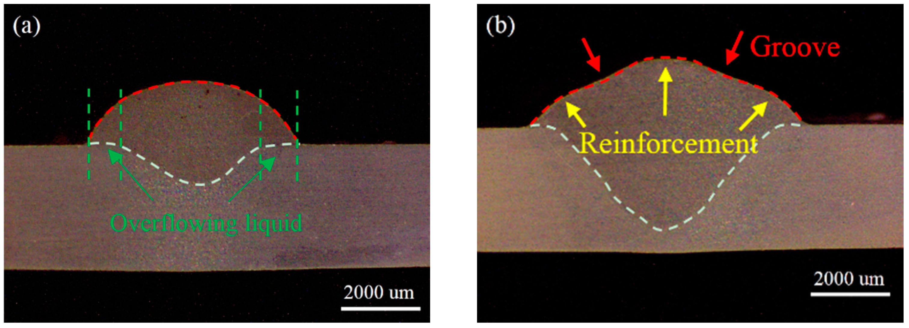

Figure 3.
Dimensions of beads welded with different average currents. (a) Area of different parts. (b) Height of different parts.
Figure 3.
Dimensions of beads welded with different average currents. (a) Area of different parts. (b) Height of different parts.

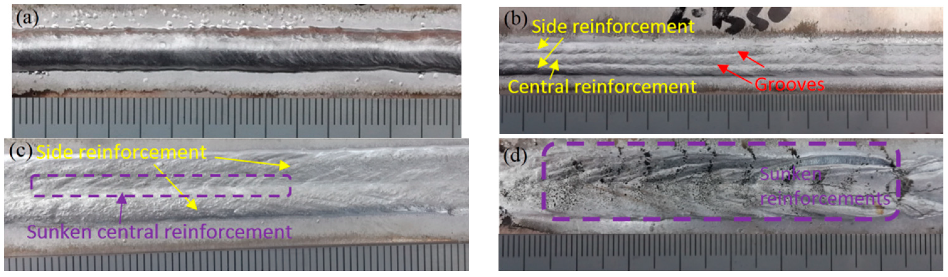
Figure 4.
Appearances of the top surface for bead welded with different average current. (a) Less than 88A; (b) 104 A; (c) 120 A; (d) 136 A.
Figure 4.
Appearances of the top surface for bead welded with different average current. (a) Less than 88A; (b) 104 A; (c) 120 A; (d) 136 A.

Figure 5.
The formation mechanism for different weld beads. (a) Simulated flow pattern of droplet impingement (reproduced from [18], with permission of Elsevier, 2016); (b) schematic of bead profile welded with current no more than 88 A; (c) schematic of bead profile welded with 104 A; (d) profile of simulation with and without droplet impingement (X = 13 mm) (reproduced from [10], with permission of Springer, 2018); (e) schematic of bead profile welded with 120 A; (f) profile of simulation with and without droplet impingement (X = 8 mm) (reproduced from [10], with permission of Springer, 2018); (g) schematic of bead profile welded with 136 A; (h) width excess of the top reinforcement over the bottom one.


Table 1.
Chemical compositions of AA6061 and ER4043 (wt%).
| Material | Mg | Si | Fe | Cu | Mn | Cr | Al |
|---|---|---|---|---|---|---|---|
| AA6061 | 0.96 | 0.52 | 0.25 | 0.25 | 0.12 | 0.26 | Bal. |
| ER4043 | 0.05 | 5.60 | 0.80 | 0.30 | 0.05 | – | Bal. |
Table 2.
Welding process parameters for P-GMAW.
| Process Parameters | Value |
|---|---|
| Mean voltage (V) | 24.3 |
| Mean current (A) | A: 72 B: 88 C: 104 D: 120 E: 136 |
| Wire feeding rate (mm/s) | A: 61 B: 71 C: 82 D: 94 E: 103 |
| Wire diameter (mm) | 1.2 |
| Welding speed (mm/s) | 10 |
© 2019 by the authors. Licensee MDPI, Basel, Switzerland. This article is an open access article distributed under the terms and conditions of the Creative Commons Attribution (CC BY) license (http://creativecommons.org/licenses/by/4.0/).
Share and Cite
MDPI and ACS Style
Zhang, Z.; Xue, J. Profile Map of Weld Beads and Its Formation Mechanism in Gas Metal Arc Welding. Metals 2019, 9, 146. https://doi.org/10.3390/met9020146
AMA Style
Zhang Z, Xue J. Profile Map of Weld Beads and Its Formation Mechanism in Gas Metal Arc Welding. Metals. 2019; 9(2):146. https://doi.org/10.3390/met9020146
Chicago/Turabian StyleZhang, Zhanhui, and Jiaxiang Xue. 2019. "Profile Map of Weld Beads and Its Formation Mechanism in Gas Metal Arc Welding" Metals 9, no. 2: 146. https://doi.org/10.3390/met9020146
Note that from the first issue of 2016, this journal uses article numbers instead of page numbers. See further details here.