The Influence of Assembly Force on the Material Loss at the Metallic Head-Neck Junction of Hip Implants Subjected to Cyclic Fretting Wear


Abstract
:1. Introduction
2. Methods
2.1. Fretting Wear Model Development
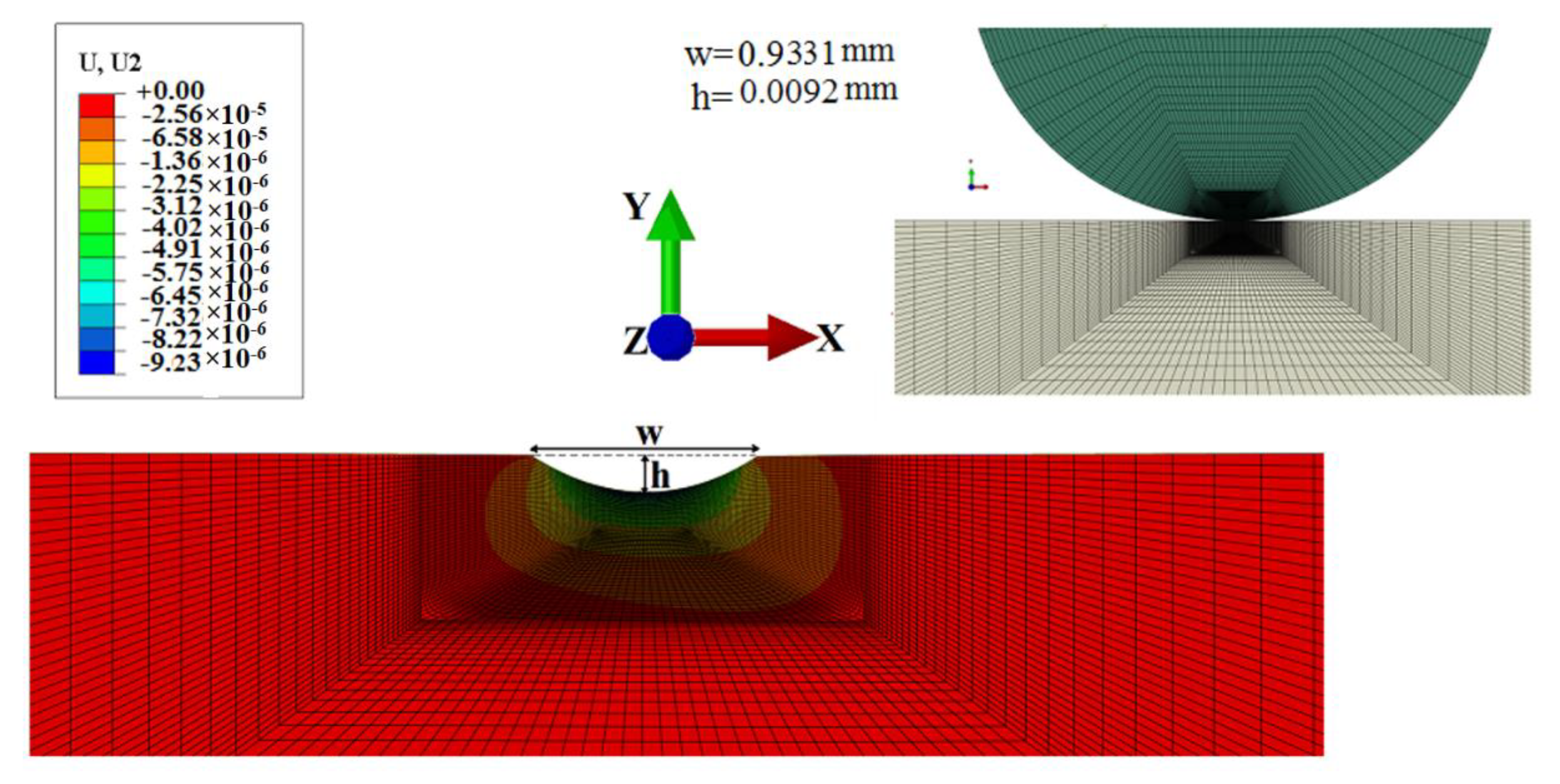
2.1.1. Verification
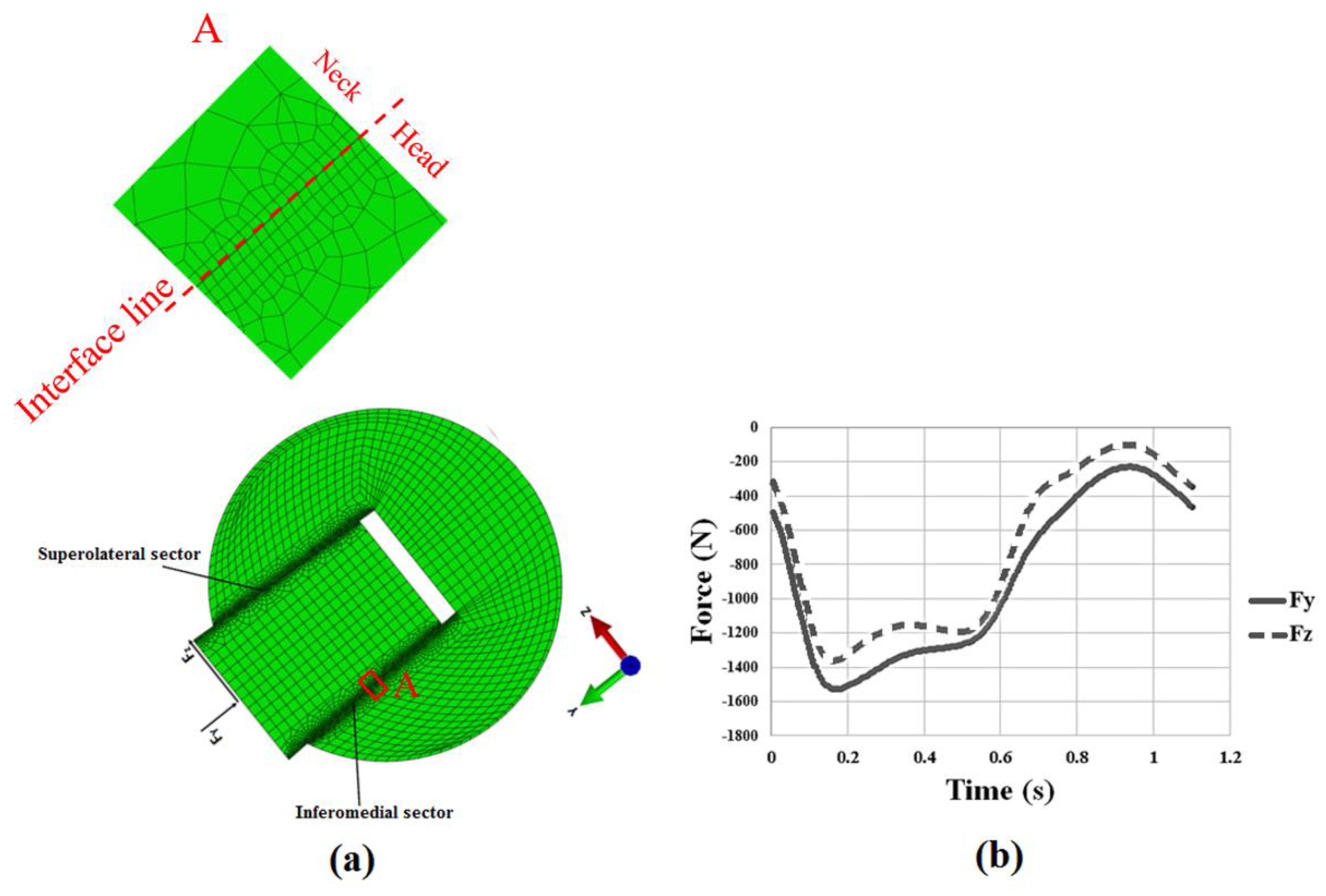
2.1.2. Fretting Wear Model for the Head-Neck Taper Junction
3. Results
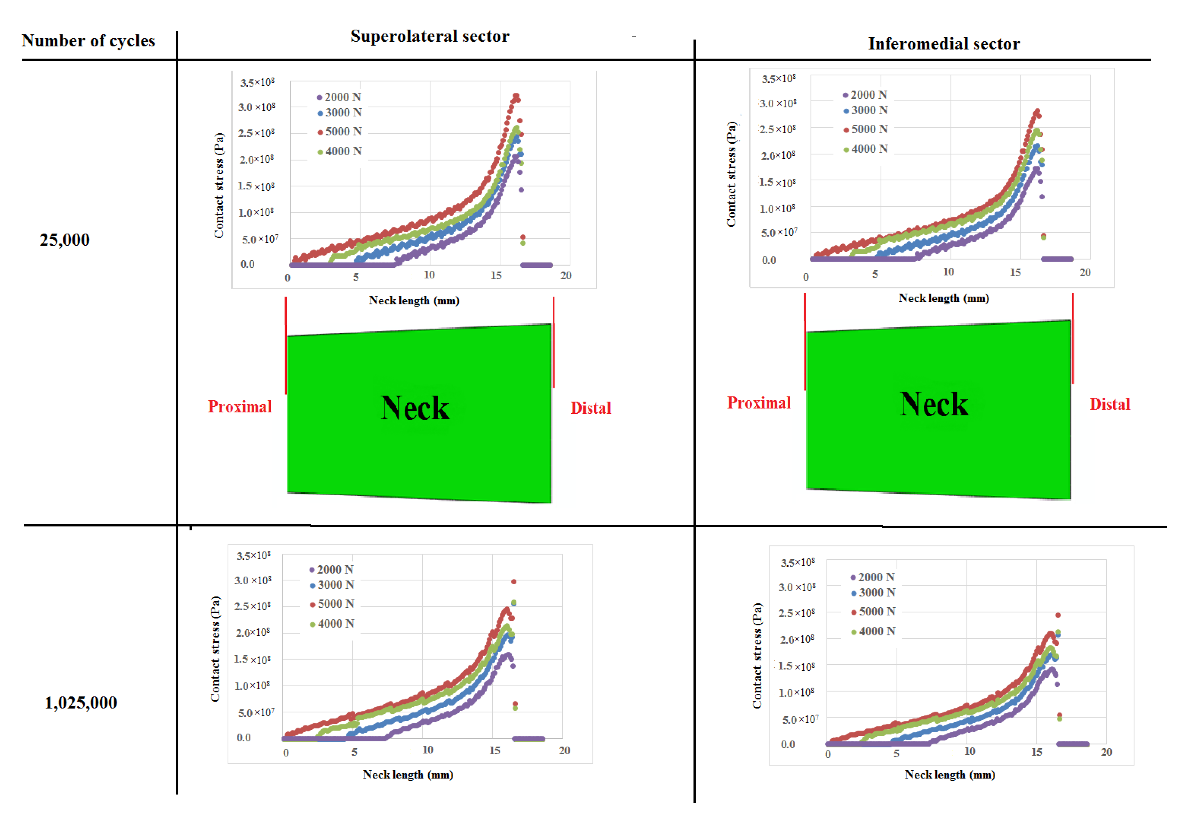
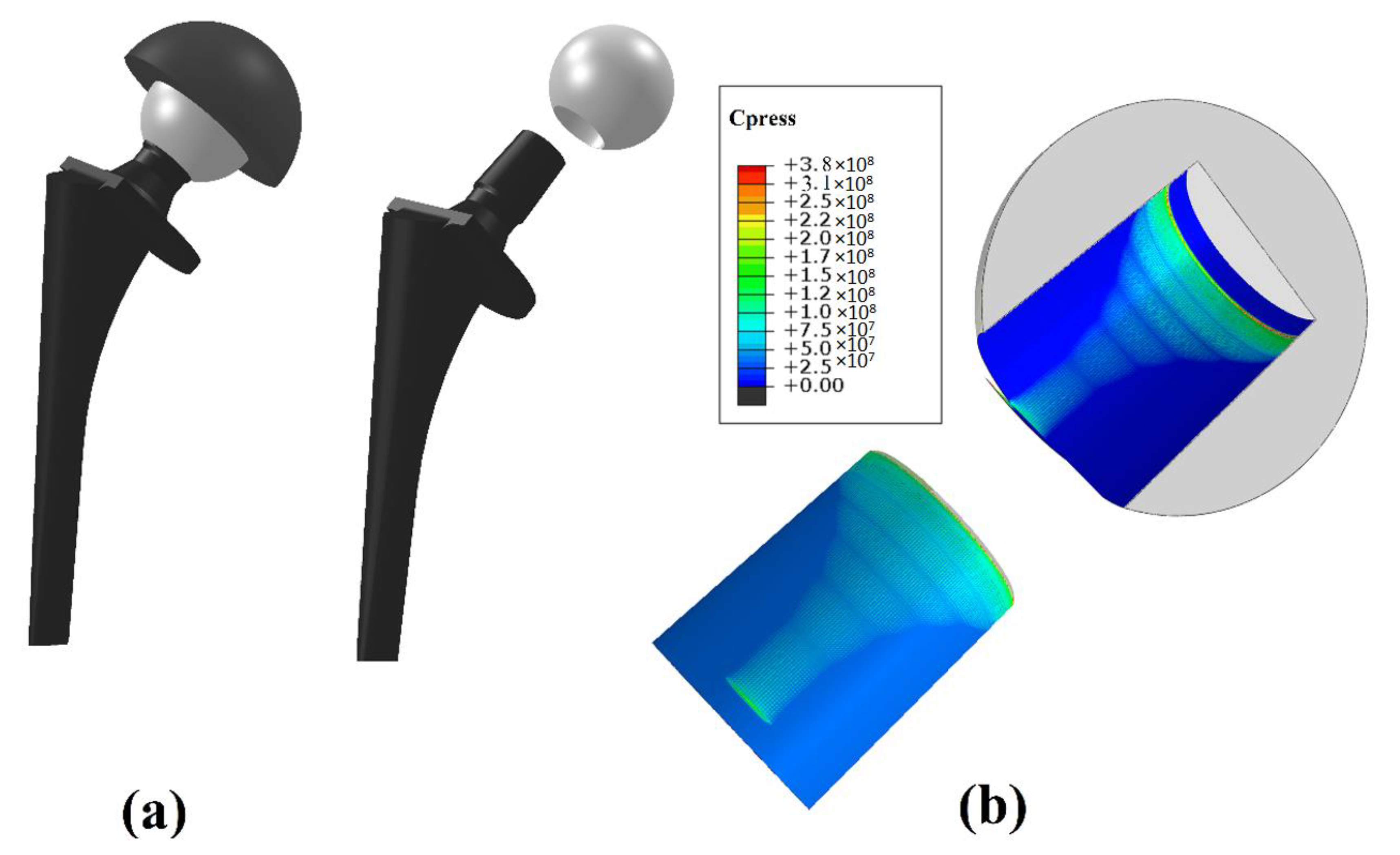
3.1. Contact Pressure and Contact Length
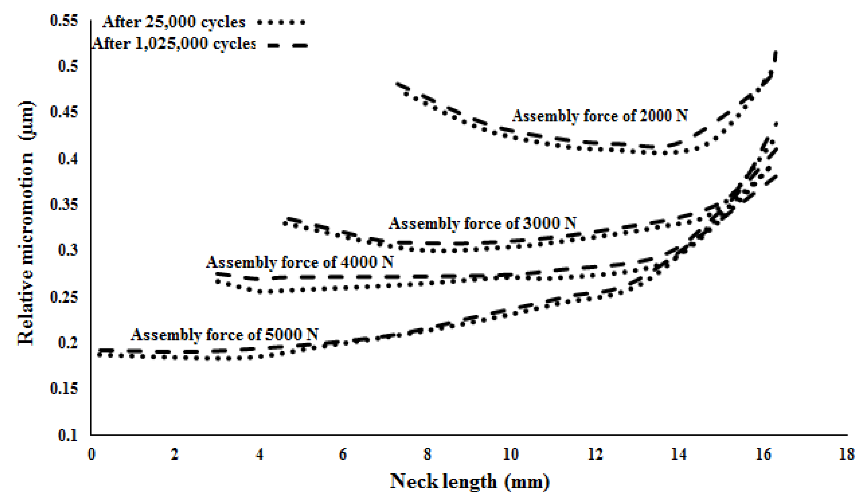
3.2. Micro-Motions
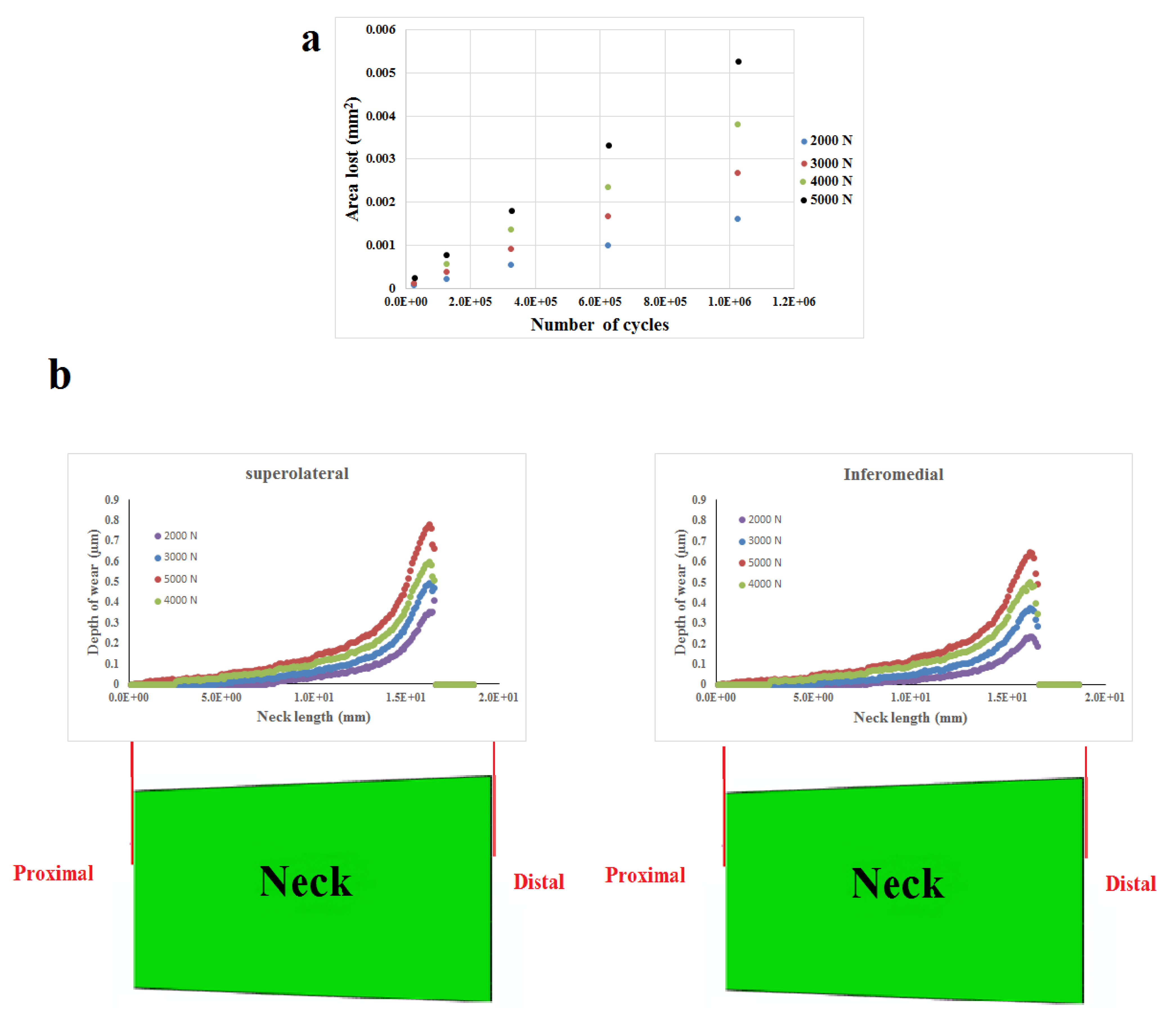
3.3. Material Loss
4. Discussion
5. Conclusions
Author Contributions
Funding
Acknowledgments
Conflicts of Interest
References
- Gilbert, J.L.; Buckley, C.A.; Jacobs, J.J. In vivo corrosion of modular hip prosthesis components in mixed and similar metal combinations. The effect of crevice, stress, motion, and alloy coupling. J. Biomed. Mater. Res. 1993, 27, 1533–1544. [Google Scholar] [CrossRef] [PubMed]
- Oskouei, R.; Fallahnezhad, K.; Kuppusami, S. An Investigation on the Wear Resistance and Fatigue Behaviour of Ti-6Al-4V Notched Members Coated with Hydroxyapatite Coatings. Materials 2016, 9, 111. [Google Scholar] [CrossRef] [PubMed]
- Chana, R.; Esposito, C.; Campbell, P.A.; Walter, W.K.; Walter, W.L. Mixing and matching causing taper wear: Corrosion associated with pseudotumour formation. J. Bone Joint Surg. Br. 2012, 94, 281–286. [Google Scholar] [CrossRef]
- Fricka, K.B.; Ho, H.; Peace, W.J.; Engh, C.A., Jr. Metal-on-Metal Local Tissue Reaction Is Associated With Corrosion of the Head Taper Junction. J. Arthroplast. 2012, 27, 26–31. [Google Scholar] [CrossRef]
- Hussenbocus, S.; Kosuge, D.; Solomon, L.B.; Howie, D.W.; Oskouei, R.H. Head-neck taper corrosion in hip arthroplasty. BioMed Res. Int. 2015, 2015, 9. [Google Scholar] [CrossRef]
- Fallahnezhad, K.; Farhoudi, H.; Oskouei, R.H.; Taylor, M. Influence of geometry and materials on the axial and torsional strength of the head-neck taper junction in modular hip replacements: A finite element study. J. Mech. Behav. Biomed. Mater. 2016, 60, 118–126. [Google Scholar] [CrossRef] [PubMed]
- Donaldson, F.E.; Coburn, J.C.; Siegel, K.L. Total hip arthroplasty head-neck contact mechanics: A stochastic investigation of key parameters. J. Biomech. 2014, 47, 1634–1641. [Google Scholar] [CrossRef]
- Gührs, J.; Körner, M.; Bechstedt, M.; Krull, A.; Morlock, M.M. Stem taper mismatch has a critical effect on ceramic head fracture risk in modular hip arthroplasty. Clin. Biomech. 2017, 41, 106–110. [Google Scholar] [CrossRef] [PubMed]
- Kocagöz, S.B.; Underwood, R.J.; Sivan, S.; Gilbert, J.L.; MacDonald, D.W.; Day, J.S.; Kurtz, S.M. Does Taper Angle Clearance Influence Fretting and Corrosion Damage at the Head-Stem Interface? A Matched Cohort Retrieval Study. Semin. Arthroplast. 2013, 24, 246–254. [Google Scholar] [CrossRef]
- Farhoudi, H.; Fallahnezhad, K.; Oskouei, R.H.; Taylor, M. A finite element study on the mechanical response of the head-neck interface of hip implants under realistic forces and moments of daily activities: Part 1, level walking. J. Mech. Behav. Biomed. Mater. 2017, 75, 470–476. [Google Scholar] [CrossRef]
- Fallahnezhad, K.; Farhoudi, H.; Oskouei, R.H.; Taylor, M. A finite element study on the mechanical response of the head-neck interface of hip implants under realistic forces and moments of daily activities: Part 2. J. Mech. Behav. Biomed. Mater. 2018, 77, 164–170. [Google Scholar] [CrossRef]
- Rehmer, A.; Bishop, N.E.; Morlock, M.M. Influence of assembly procedure and material combination on the strength of the taper connection at the head-neck junction of modular hip endoprostheses. Clin. Biomech. (Bristol, Avon) 2012, 27, 77–83. [Google Scholar] [CrossRef] [PubMed]
- Georgiou, G.; Siapkara, A.; Dimitrakopoulou, A.; Provelengios, S.; Dounis, E. Dissociation of bipolar hemiarthroplasty of the hip after dislocation. Injury 2006, 37, 162–168. [Google Scholar] [CrossRef]
- Ramoutar, D.N.; Crosnier, E.A.; Shivji, F.; Miles, A.W.; Gill, H.S. Assessment of Head Displacement and Disassembly Force With Increasing Assembly Load at the Head/Trunnion Junction of a Total Hip Arthroplasty Prosthesis. J. Arthroplast. 2017, 32, 1675–1678. [Google Scholar] [CrossRef] [PubMed]
- Nassutt, R.; Mollenhauer, I.; Klingbeil, K.; Henning, O.; Grundei, H. Relevance of the insertion force for the taper lock reliability of a hip stem and a ceramic femoral head. Biomed. Tech. Biomed. Eng. 2006, 51, 103–109. [Google Scholar] [CrossRef] [PubMed]
- Pennock, A.T.; Schmidt, A.H.; Bourgeault, C.A. Morse-type tapers: Factors that may influence taper strength during total hip arthroplasty. J. Arthroplast. 2002, 17, 773–778. [Google Scholar] [CrossRef]
- Scholl, L.; Longaray, J.; Raja, L.; Lee, R.; Faizan, A.; Herrera, L.; Thakore, M.; Nevelos, J. Friction in modern total hip arthroplasty bearings: Effect of material, design, and test methodology. Proc. Inst. Mech. Eng. Part H J. Eng. Med. 2015, 230, 50–57. [Google Scholar] [CrossRef]
- Bitter, T.; Khan, I.; Marriott, T.; Lovelady, E.; Verdonschot, N.; Janssen, D. A combined experimental and finite element approach to analyse the fretting mechanism of the head-stem taper junction in total hip replacement. Proc. Inst. Mech. Eng. Part H J. Eng. Med. 2017, 231, 862–870. [Google Scholar] [CrossRef] [PubMed]
- Witt, F.; Gührs, J.; Morlock, M.M.; Bishop, N.E. Quantification of the contact area at the head-stem taper interface of modular hip prostheses. PLoS ONE 2015, 10, e0135517. [Google Scholar] [CrossRef]
- Dyrkacz, R.M.R.; Brandt, J.M.; Morrison, J.B.; O’Brien, S.T.; Ojo, O.A.; Turgeon, T.R.; Wyss, U.P. Finite element analysis of the head-neck taper interface of modular hip prostheses. Tribol. Int. 2015, 91, 206–213. [Google Scholar] [CrossRef]
- English, R.; Ashkanfar, A.; Rothwell, G. A computational approach to fretting wear prediction at the head–stem taper junction of total hip replacements. Wear 2015, 338–339, 210–220. [Google Scholar] [CrossRef]
- English, R.; Ashkanfar, A.; Rothwell, G. The effect of different assembly loads on taper junction fretting wear in total hip replacements. Tribol. Int. 2016, 95, 199–210. [Google Scholar] [CrossRef]
- Fallahnezhad, K.; Oskouei, R.H.; Badnava, H.; Taylor, M. An adaptive finite element simulation of fretting wear damage at the head-neck taper junction of total hip replacement: The role of taper angle mismatch. J. Mech. Behav. Biomed. Mater. 2017, 75, 58–67. [Google Scholar] [CrossRef] [PubMed]
- Farhoudi, H.; Oskouei, R.H.; Jones, C.F.; Taylor, M. A novel analytical approach for determining the frictional moments and torques acting on modular femoral components in total hip replacements. J. Biomech. 2015, 48, 976–983. [Google Scholar] [CrossRef] [PubMed]
- Farhoudi, H.; Oskouei, R.; Pasha Zanoosi, A.; Jones, C.; Taylor, M. An Analytical Calculation of Frictional and Bending Moments at the Head-Neck Interface of Hip Joint Implants during Different Physiological Activities. Materials 2016, 9, 982. [Google Scholar] [CrossRef]
- Archard, J. Contact and rubbing of flat surfaces. J. Appl. Phys. 1953, 24, 981–988. [Google Scholar] [CrossRef]
- Johansson, L. Numerical Simulation of Contact Pressure Evolution in Fretting. J. Tribol. 1994, 116, 247–254. [Google Scholar] [CrossRef]
- Ding, J.; Leen, S.B.; McColl, I.R. The effect of slip regime on fretting wear-induced stress evolution. Int. J. Fatigue 2004, 26, 521–531. [Google Scholar] [CrossRef]
- McColl, I.R.; Ding, J.; Leen, S.B. Finite element simulation and experimental validation of fretting wear. Wear 2004, 256, 1114–1127. [Google Scholar] [CrossRef]
- Fallahnezhad, K.; Oskouei, R.H.; Taylor, M. Development of a fretting corrosion model for metallic interfaces using adaptive finite element analysis. Finite Elem. Anal. Des. 2018, 148, 38–47. [Google Scholar] [CrossRef]
- Maruyama, N.; Kawasaki, H.; Yamamoto, A.; Hiromoto, S.; Imai, H.; Hanawa, T. Friction-wear properties of nickel-free co-cr-mo alloy in a simulated body fluid. Mater. Trans. 2005, 46, 1588–1592. [Google Scholar] [CrossRef]


| Comparison | Wear Profile Parameters on the Surface of the Disc | After 1000 Cycles | After 5000 Cycles | After 18,000 Cycles |
|---|---|---|---|---|
| Results of this work | Width, w (mm) | 0.3512 | 0.7123 | 0.9331 |
| Height, h (mm) | 0.0013 | 0.0042 | 0.0092 | |
| Results reported by Ding et al. [28] | Width, w (mm) | 0.3834 | 0.7644 | 0.9754 |
| Height, h (mm) | 0.0013 | 0.0042 | 0.0092 |
© 2019 by the authors. Licensee MDPI, Basel, Switzerland. This article is an open access article distributed under the terms and conditions of the Creative Commons Attribution (CC BY) license (http://creativecommons.org/licenses/by/4.0/).
Share and Cite
Fallahnezhad, K.; Oskouei, R.H.; Badnava, H.; Taylor, M. The Influence of Assembly Force on the Material Loss at the Metallic Head-Neck Junction of Hip Implants Subjected to Cyclic Fretting Wear. Metals 2019, 9, 422. https://doi.org/10.3390/met9040422
Fallahnezhad K, Oskouei RH, Badnava H, Taylor M. The Influence of Assembly Force on the Material Loss at the Metallic Head-Neck Junction of Hip Implants Subjected to Cyclic Fretting Wear. Metals. 2019; 9(4):422. https://doi.org/10.3390/met9040422
Chicago/Turabian StyleFallahnezhad, Khosro, Reza H. Oskouei, Hojjat Badnava, and Mark Taylor. 2019. "The Influence of Assembly Force on the Material Loss at the Metallic Head-Neck Junction of Hip Implants Subjected to Cyclic Fretting Wear" Metals 9, no. 4: 422. https://doi.org/10.3390/met9040422