3D Printed Acetabular Cups for Total Hip Arthroplasty: A Review Article


Institute of Orthopaedics and Musculoskeletal Science, University College London and the Royal National Orthopaedic Hospital, Stanmore HA7 4LP, UK
*
Author to whom correspondence should be addressed.
Metals 2019, 9(7), 729; https://doi.org/10.3390/met9070729
Submission received: 31 May 2019
/
Revised: 17 June 2019
/
Accepted: 26 June 2019
/
Published: 28 June 2019
(This article belongs to the Special Issue Failure Analysis of Biometals)
Abstract
:Three-dimensional (3D) printed titanium orthopaedic implants have recently revolutionized the treatment of massive bone defects in the pelvis, and we are on the verge of a change from conventional to 3D printed manufacture for the mass production of millions of off-the-shelf (non-personalized) implants. The process of 3D printing has many adjustable variables, which taken together with the possible variation in designs that can be printed, has created even more possible variables in the final product that must be understood if we are to predict the performance and safety of 3D printed implants. We critically reviewed the clinical use of 3D printing in orthopaedics, focusing on cementless acetabular components used in total hip arthroplasty. We defined the clinical and engineering rationale of 3D printed acetabular cups, summarized the key variables involved in the manufacturing process that influence the properties of the final parts, together with the main limitations of this technology, and created a classification according to end-use application to help explain the controversial and topical issues. Whilst early clinical outcomes related to 3D printed cups have been promising, in-depth robust investigations are needed, partly because regulatory approval systems have not fully adapted to the change in technology. Analysis of both pristine and retrieved cups, together with long-term clinical outcomes, will help the transition to 3D printing to be managed safely.
1. Introduction
Three-dimensional (3D) printing, also known as ‘Additive Manufacturing’ (AM), of titanium orthopaedic implants has revolutionized the treatment of massive bone defects in the pelvis due to their ability to be customized with complex shapes, size and surface geometries; this is more complicated to achieve with conventional manufacturing (i.e., non-3D printing) methods, such as drop forging and machining, which are commonly used to produce orthopaedic implants. The greatest impact of 3D printing of orthopaedic implants is, however, still to come: the mass production of millions of off-the-shelf (non-personalized) implants.
Every year, over 600,000 total hip arthroplasty (THA) procedures are performed in Europe and 1.4 million worldwide; these numbers are expected to grow significantly by 2030 [1,2,3]. The main clinical rationale for the use of 3D printed off-the-shelf implants is achieving a successful long-term fixation with bone to restore biomechanical function of the joint.
The process of 3D printing has many adjustable variables which, taken together with the possible variation in designs that can be printed, has created even more variables in the final product that must be understood if we are to predict the safety and performance of 3D printed implants [4,5,6,7]. The regulatory approval systems have not yet completely caught up with the change in technology [8]; surgeons prefer to use implants that have been followed up for several years and have been highly rated by systems such as the Orthopaedic Data Evaluation Panel (ODEP, UK) [9]. Orthopaedics has already shown cases of unpredictable outcomes with design solutions that were thought to be revolutionary, such as metal-on-metal hip replacements [10,11].
This review aims to describe the role of 3D printing of orthopaedic implants, focusing on acetabular components used in THA. To achieve this, we (1) explain the rationale for 3D printed acetabular cups, (2) describe the variables and the limitations involved in the 3D printing manufacture, and (3) suggest a classification for these cups, presenting also the investigation methods and the clinical outcomes of 3D printed cups.
2. Rationale for 3D Printing in Orthopaedics
Although the majority of THA procedures are still performed using conventionally manufactured cups, acetabular components produced using 3D printing technologies are being increasingly used for primary and revision hip surgeries. There are advantages and disadvantages of each production techniques (Table 1). In terms of manufacturing, 3D printing enables complex porous structures with specifically designed pores shapes to be produced, unlike conventional technologies, where the control over the final architecture of the porous backside coating is limited. Furthermore, customization of implants can be achieved more easily using 3D printing. In terms of clinical outcomes and investigation of the implants, the conventional cups have a long-track record, with long-term clinical results, unlike 3D printed; however, aseptic loosening (i.e., loss of fixation without infection) is still one of the most common reasons for revision [12]. Independent investigations of full-post production 3D printed acetabular components are currently missing.
2.1. Clinical Rationale for 3D Printed Cups
Customized implants
The clinical unmet need addressed by customized 3D printed titanium acetabular implants was the poor outcome resulting from the use of conventionally manufactured triflange implants, jumbo cup, cages and augments to reconstruct massive acetabular defects [14,15,16,17,18]. These defects most commonly occur following previous failed implants. Conventionally manufactured implants failed due to poor fixation to the bone as a result of the complex shape of the defect and low surface area of host bone with good blood supply. 3D printed implants have overcome both of these problems (Figure 1a).
Off-the-shelf
One of the commonest reasons for the failure of orthopaedic implants is loosening from the bone [19]. Several factors are responsible for this including poor bone quality, the presence of metabolic bone diseases, pathological bone anatomy or conditions due to previous surgeries [20,21]. 3D printing creates implants with highly porous structures for enhanced fixation, matching bone characteristics such as pore size, coefficient of friction and modulus of elasticity to avoid stress shielding. Porosity and properties similar to cancellous bone may enable bone-implant interactions that lead to primary stability, bone ingrowth and osseointegration [22].
3D printed, off-the-shelf implants can also be designed to optimize hip joint biomechanics and cup size. Surgeons try to use the 36 mm heads for greater stability [23,24], but this is difficult to achieve with conventional implants in a size suitable for most women unless they can be made with thinner walls. 3D printing can achieve this, allowing surgeons to use large femoral head size options (e.g., 36 mm diameter) with smaller acetabular cups (e.g., 48 mm diameter). It is not clear, however, what impact this design modification may have on the mechanical properties of the cup (Figure 1b).
2.2. Engineering Rationale for 3D Printed Cups
The ISO/ASTM 52900 standard defines 3D printing as ‘the process of joining materials to make parts from 3D model data, usually layer upon layer, as opposed to subtractive manufacturing and formative manufacturing methodologies’ [25]. From an engineering perspective, the greatest advantage of 3D printing, when compared to conventional techniques, is the design freedom enabled during the Computer Aided Design (CAD) process. Unlike conventional methods, tools such as molds are not needed, reducing the cost of the final part; therefore, increased complexity in the structure of the 3D printed object does not involve higher costs.
To date, 3D printing involves a lower cost-per-part than conventional manufacturing when the number of parts is below a certain threshold, but with the increased adoption of this manufacturing technique, this threshold will grow [6]. It has also been estimated that the consumption of raw materials may be reduced up to 75% [26]. Acetabular cups with complex architecture and controlled mesostructure (structure associated with pores and porosity) can be designed and made, integrating porous and dense regions.
3. 3D Printing Manufacturing Process, Limitations and Risks
Both conventional and 3D printing technology use Titanium-6-Aluminum-4-Vanadium (Ti6Al4V) alloy, due to its biocompatibility, mechanical strength and corrosion resistance [27,28]. Guidelines regarding the properties of Ti6Al4V as a material for surgical implants are defined by both the International Organization for Standardization (ISO) and the American Society for Testing and Material (ASTM) standards [29,30,31]. However, we must be aware of the limitations and risks of defects that are unique to the 3D printing process, together with the potential impacts of these when present in orthopaedic implants.
3.1. Manufacturing Process
Conventional manufacturing technologies start production of the implant from a dense block that is machined into the shape of an acetabular component, using techniques such as computer numerical controlled (CNC) machining of wrought or cast bars, powder metallurgy, drop forging and casting [27,32]. The component is then finished using wet or coarse blasting on the external surface to obtain roughened areas, and post-processing the internal surface to obtain the required dimensional tolerances and minimal friction for an optimal seating of the liner [27]. The backside coating is applied at a later step using different methods such as solid state processing (powder metallurgy, sintering of powders and fibres), vapour deposition or plasma spray [22,33,34,35].
The 3D printing, or additive manufacturing, methods used to manufacture acetabular cups are classified as Powder Bed Fusion (PBF) technologies, where an energy source (laser or electron beam) selectively melts specific regions of a powder bed. Two different processes fall under the PBF category: selective laser melting (SLM) [36,37] and electron beam melting (EBM) [7,38,39,40,41]. In the pastdecade 3D printing has evolved, leading in 2007 to the first acetabular component produced using EBM to obtain the CE-certification (Figure 2) [42]. To date, several companies have commercialized machines with laser powder-bed hardware (EOS GmbH, Kraillin, Germany; SLM Solutions, Lübeck, Germany; Concept Laser, GE Additive, Lichtenfels, Germany; Renishaw, Wotton-under-Edge, UK; 3D Systems, Rock Hill, SC, USA) and one company (Arcam, GE Additive, Mölndal, Sweden) with electron beam as the energy source [6,43,44].
These 3D printing processes are guided by CAD files containing the model of the part to manufacture. With the layer-over-layer process, once a layer of powder has been selectively melt, the build platform is lowered, new powder is deposited and raked, and the process is repeated until the object is built [45]. Adherence of the current layer to the rest of the part is achieved by re-melting of previous layers. The whole implant (dense and porous parts) is produces in a single step, although post-processing such as powder removal, heat treatment or post-machining are required [4,6,37,43,44]. It has been estimated that more than 130 variables are involved in PBF [46,47]; a schematic summary of some of these variables is presented in Figure 3.
The feedstock quality is the first ‘macro-variable’ to determine the properties of the final implant. Powder characteristics, such as size, shape, chemical composition and surface morphology depend on the powder production technique (gas atomization, rotary atomization, plasma rotating electrode process, plasma atomization); these influence properties like flowability (how well a powder flows), apparent density (how well a powder packs) and thermal conductivity of the whole powder bed [43,44]. Smaller powder particles are used in SLM, compared to EBM, leading to a smoother surface finish due to decrease of the size of satellites formed during melting and reduction of layer thickness; this has an effect on the overall roughness, which is higher in EBM-manufactured components [44]. Moreover, powder chemical composition must be within the alloy specifications, especially when the material is recycled and the possibility of contamination with oxygen or other gases is present. It has been demonstrated that oxygen content can increase up to 0.19% in weight over 21 reuse cycles [48], implying that powder can be reused, but titanium and its alloys are known to oxidize and suffer embrittlement when the oxygen content increases [49].
The second ‘macro-variable’ is defined by the software system; the CAD model represents the ideal final shape of the part to build, but it has to be converted into a surface tessellation format (STL) and sliced into layers in order to generate the manufacturing information for each cross-section. The conversion CAD-to-STL may represent a source of error with loss of resolution because the STL format simplifies the component geometry into a set of triangular facets connected at the vertices [4,47,50]. Moreover, the spatial position and the orientation of the components in the build chamber may influence the geometrical accuracy of the part, because different temperature gradients can result in the powder bed [51].
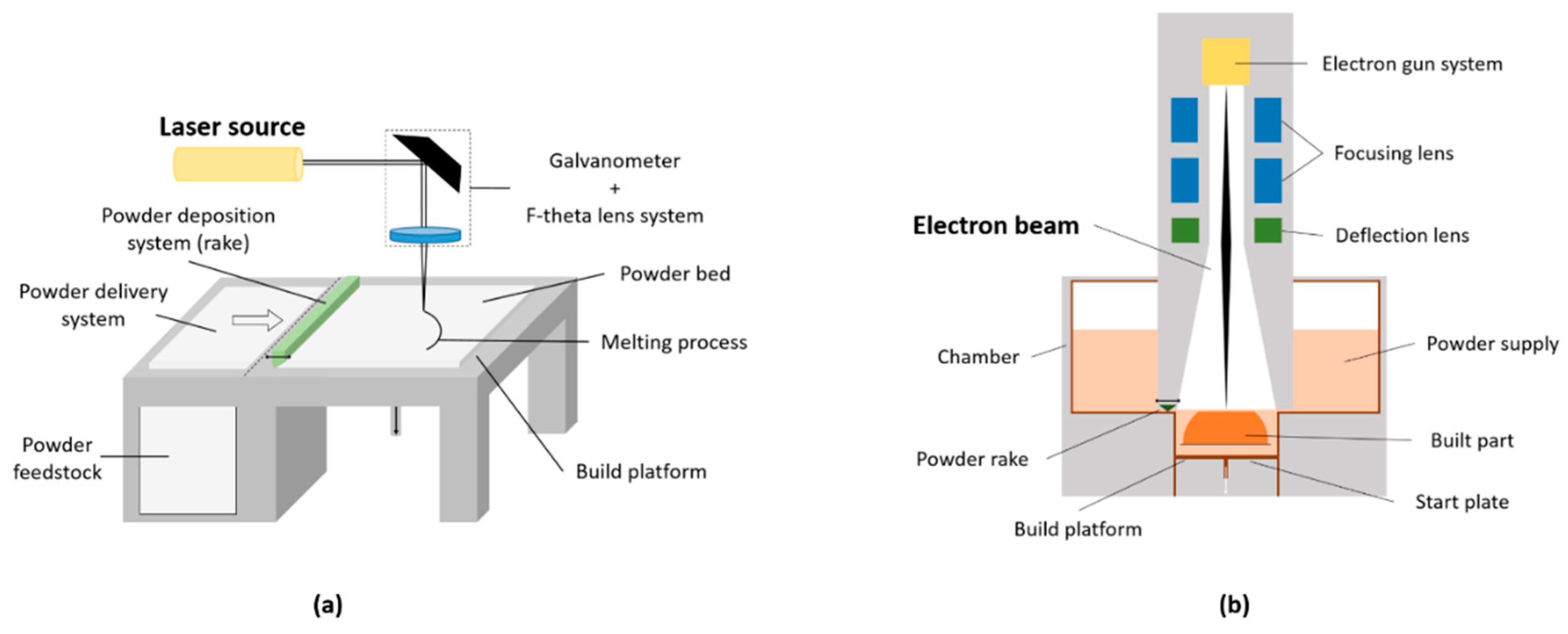
The third ‘macro-variable’ is represented by the hardware of the machine. SLM works using a laser source, a system of lenses and a galvanometer (scanning mirror) to position the beam; the laser heats and melts the powder when photons are absorbed by the powder particles (Figure 4a). EBM uses a filament (usually made of tungsten) as source of electrons, a magnetic coil to collimate and deflect the beam spatially and a column for the electron beam, resembling a high-power scanning electron microscopy (SEM) (Figure 4b). In this case, the powder is heated by the transfer of kinetic energy from incoming electrons, generating also increasingly negative charge on the powder bed. In order to reduce this, the EBM energy is more diffuse (i.e., larger heat-affected powder zone) and helium gas is injected during melting to dissipate the charge; this leads to a larger minimum feature size that can be produced and to the use of larger powder particle size [34,43,44,45]. In general, the small feature size that both SLM and EBM can manufacture allows to print the meshes or foam structures that are present in orthopaedic implants such as acetabular cups [52].
Other variables to be considered in the 3D printing processes can be summarized as follows: scan speed, which is higher in EBM because magnetically driven, while in SLM depends on the galvanometer inertia; layer thickness, which determines how much powder is distributed to the melt surface and is greater in EBM because of larger powder particles size and beam focusing; powder deposition, which is delivered by a powder hopper and a metal rake in EBM and by variable feeding systems (hopper or dispersing piston) and re-coating systems (soft blades or roller) in SLM; build chamber atmosphere, which is filled with inert gas (argon or nitrogen) to avoid oxidation in SLM and is under vacuum (<5 × 10⁻⁴ Pa) to generate the electrons and prevent any contamination in EBM [43,44].
A fundamental step of the building process is the cooling phase, which determines both microstructural and mechanical properties of the 3D printed part. This process is influenced by parameters such as scan strategy (path followed by the heating source) and temperature of the powder bed. The higher energy input of the electron beam heats the surrounding loose powder, generating a higher temperature in the chamber (400–1000 °C), compared to SLM (100–200 °C), where heaters are used to avoid temperature drops on the build platform. Therefore, the thermal cycling experienced by the metal (simultaneous melting of the top powder, re-melting of underlying layers and cooling) is different between the two PBF techniques, resulting in different microstructure (grain size and orientation, phase distribution). Laser-built components experience the presence of residual stresses which must be relieved [4,43,44]. A summary of the differences between SLM and EBM is presented in Table 2.
At the end of the building process, the part is considered “as-fabricated” and requires post-processing steps. Excess powder and support structures must be removed; thermal treatment can be applied to reduce residual stresses in the structure and enhance the overall mechanical properties. Machining can also be used to modify the surface finish, influencing the actual part tolerance, minimum feature size and surface roughness of the end-use component. As example, surface roughness is influenced by the layering effect (‘stair-step effect’), by the actual roughness of the powder particles (finer powder means smaller satellites formation) and by post-processing steps. Similarly, the geometrical accuracy depends on the setup of the machine and post-processing treatments [43,44]; it has been suggested that EBM tolerance capability is about ±250/300 µm [53,54].
The mechanical properties of the final part depend on the microstructure that is formed during the building process, which in turn depends on the parameters of the technology [45].
At room temperature, the Ti6Al4V alloy is made of α- and β-phases; after being processed using EBM or SLM, different microstructures are generated [43]. The low cooling rate experienced during EBM enables the β-phase formed during the process to transform back to α-phase, whilst the high cooling rate of SLM generates martensitic α’-phase. This is usually removed using post-processing heat treatments. Overall, the thermal history (melting and cooling), the quality of the feedstock, the potential presence of structural defects, the component size, the energy source density and the scanning strategy are the main factors affecting the final mechanical properties [55,56,57]. The layer-over-layer building process also creates anisotropy in the build direction (i.e., Z-direction).
If the 3D printed part also includes porous structures, as with acetabular cups, the mechanical properties of the whole component will differ and depend on the behaviour of this region, as demonstrated by Murr et al. [13]
3.2. Limitations and Potential Risks of 3D Printing
Dimensional accuracy, optimal surface roughness and minimization of residual stresses in the material structure are key aspects of 3D printed parts for critical applications like medical implants. These can be achieved choosing the most adequate powder feedstock, correctly designing the final object and selecting the best machine parameters. However, 3D printing shows limitations that leads to the presence of defects in the built part.
One of the most common limitation is represented by the presence of voids or pores in the structure of the final part, which can affect its mechanical properties [45]. These defects can be due to the properties of the powder feedstock or to suboptimal building conditions. Spherical gas pores entrapped in the powder particles can be transferred to the final object if the powder is not completely melted; similarly, gasses of the build chamber can be entrapped in the melt pool during the process, resulting in spherical voids [61]. Another source of defects is the so-called ‘keyhole melting’ mode, where the depth of the melt pool is controlled by the evaporation of the metal due to the high-power energy source. If the vapor cavity collapses, then almost spherical voids are left behind [62]. Voids with elongated shapes can also be generated if a lack of fusion between subsequent layers occurs (lack of fusion defects) [63].
Another common limitation is given by the presence of solid powder particles partially attached to the surface of the built part (Figure 5); if the energy source is too low, then the powder is not completely molten, whilst if it is too high, the molten pool can form small ‘islands’ that generate particles (‘balling phenomenon’) [45].
Cracking and delamination are other possible defects exhibited by 3D printed parts; these can occur due to solidification shrinkage (thermal contraction) of the structure, which subsequently generates tensile stresses that form cracks at the grain boundaries if the strength of the material is exceeded. When the residual stresses overcome the strength of the metal at the interface of subsequent layers, then a delamination phenomenon of these consecutive layers can occur [45]. When the temperature of the melting material is too elevated, a phenomenon of loss of alloying elements can also occur. This depends on the metal alloy and can cause modification in the alloy composition [64].
At the end of the manufacturing process, the as-fabricated part needs to be cleaned from the residual unmolten powder [43]. The complex porous structures that can be produced with 3D printing have made this cleaning process challenging [35,65,66].
Although all these limitations and the presence of defects have been widely reported in 3D printed parts, few studies have addressed this for medical implants. In a comprehensive review on additive manufacturing of medical instruments, Culmone et al. [66] highlighted how the presence of debris in the final component is still a technical issue that needs to be addressed. Another study by du Plessis et al. [67] identified pores in the material structure of a nasal cavity implant made of Ti6Al4V produced using SLM; these pores were in the range 10–60 µm, according to the region analyzed. In general, an issue found with 3D printed device related to surgery, such as anatomic models and surgical guides, is the non-satisfactory accuracy of the final components compared to the initial model [68].
It cannot be excluded that some of these defects are present in 3D printed acetabular cups, although no studies have reported this. It can be speculated that if some defects were to be found, then, there might be implications for the implant’s properties and performance. As an example, the presence of unmolten particles on the surface of the cups might lead to the release of titanium.
To date, 3D printed implants have received both the Food & Drug Administration (FDA) and CE marking approval. In the United Kingdom, three 3D printed acetabular cup designs are currently going through the Beyond Compliance initiative, which monitors new or modified implants placed on the market. The substantial equivalence to other legally marketed devices, regarding safety and effectiveness, is still applied as a principle to clear implants, including 3D printed cups. These components are treated as conventionally manufactured implants, since the intended use (i.e., acetabular component for THA) is the same [69].
4. Classification and Analysis of 3D Printed Acetabular Cups
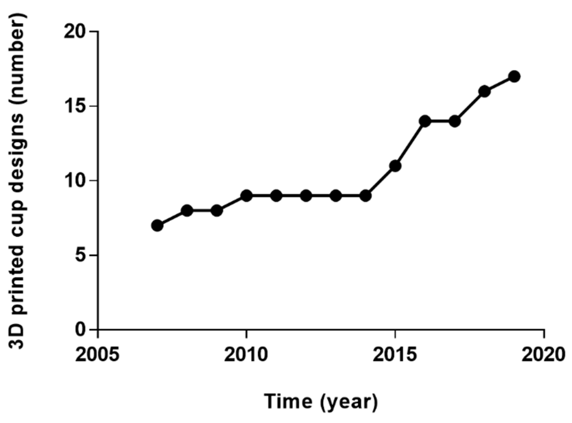
Over fifteen 3D printed acetabular cup designs are currently commercially available (Table 3); this number has grown constantly since 2007, when the first cups were released (Figure 6). It has been estimated that more than 60,000 acetabular cups produced using EBM have been used worldwide by 2017 and this number is expected to grow [39].
According to their end-use application, the cups can be classified as ‘custom’ or ‘off-the-shelf’. Considering the design of the porous structure present on the cups, another classification for 3D printed acetabular components can be suggested.
4.1. Acetabular Cup Classification: Porous Structure Design
Regardless of the end-use application, another classification may take into account the different porous architectures that each company have developed. The overall aim is to obtain an open-pore (cellular or lattice) structure that can promote bone ingrowth and prevent a later-stage loosening of the implant, avoiding micromotion over 150 µm [82]. Moreover, the porous structure can reduce the risk of stress shielding due to stiffness mismatch between the metallic implant and bone, providing a lower modulus of elasticity [13,83,84]. Similarly to implants with conventionally manufactured porous coatings, the fixation efficacy of 3D printed components strongly depends on the geometric characteristic of the porous structure [33]. A compromise in maintaining the mechanical strength while providing adequate pore size leads to different porous architectures. The majority of the specifications are proprietary but the possible methods to define the 3D porous structures are well established [34,47,85]. Regular (repeated unit cells) or irregular (stochastic, random) structures can be designed and manufactured, theoretically producing any kind of porous shape; typical design strategy for periodic regular networks include the use of CAD tools (libraries of unit cells), image-based structure taken from computed tomography (CT) or magnetic resonance imaging (MRI) data or implicit surfaces solutions, where a single mathematical equation defines the pore shape [34,85]. These solutions are usually based on a trial-and-error approach, which is why the so-called ‘topology optimization’ have been applied in order to create structures with desired properties satisfying prescribed constraints. These techniques have been thoroughly described elsewhere [34]. In general, the quality and the real dimensions of the mesh may vary significantly depending on design and fabrication process.
An example of a unit cell-based highly porous trabecular structure is represented by Trabecular Titanium (TT; Lima Corporate, Udine, Italy): a hexagon-shaped structure developed on three planes which mimics a diamond crystal (Figure 7a) [53,54,86,87]. Differently, a stochastic architecture is represented by Tritanium (Stryker, Mahwah, NJ, USA), which is a random interconnected structure with irregular pore size and shape (Figure 7b). An example of porous structure derived from human CT data is represented by OsseoTi (Zimmer Biomet, Warsaw, IN, USA).
4.2. Acetabular Cup Analysis
The number of investigations of 3D printed acetabular designs is limited. A summary of the analysis methods used for these cups is reported in Table 4.
Other investigations tools have been suggested to assess the properties of 3D printed samples, such as electron microscopy, mechanical testing and histology. However, these methods have been applied to cylindrical or cubic specimens to test the properties of the structure, evaluate bone ingrowth and the interaction with bone cells [13,32,40,52,53,92,93,94].
Non-clinical tests, defined as ‘performance tests’ in the FDA 510(k) reports, have been performed on 3D printed cups in order to determine the substantial equivalence to conventionally manufactured implants and obtain the certification. Shear testing, both static and fatigue, as well as tensile testing, deformation testing, locking mechanism strength, range of motion testing, dynamic compression, fatigue testing, push-out, lever-out and torque-out testing have been carried out based on standards [95,96,97]. However, the outcomes of such tests are not publicly available.
To date, a small number of clinical studies about 3D printed cups have been published for both off-the-shelf [73,98,99,100,101,102] and custom implants [21,78,103,104,105,106,107,108].
A registry study by Castagnini et al. [73] compared the survival rate and reason for revision of a specific 3D printed off-the-shelf design (Fixa Ti-Por; Adler Ortho, Milan, Italy) with all the other cementless cups used from July 2007 and December 2015 reported in the Registry of Prosthetics Orthopaedic Implants (RIPO). The AM socket was implanted in 9,864 cases out of 36,787, with similar patients mean age at the time of surgery (68 vs. 69 years). Significantly higher survival rate (98.7% vs. 97.9%) and lower incidence of aseptic loosening were reported for the 3D printed socket. Steno et al. [98] reported on the early outcomes (mean follow-up period of 38.14 months) of three AM designs (Delta TT, Delta ONE TT, Delta Revision TT; Lima Corporate, Udine, Italy) used in 81 revision cases (mean age 68 years) between March 2009 and May 2012. Only one re-revision was performed due to instability of the acetabular component; in general, encouraging results were showed. Perticarini et al. [99] reported good clinical and radiographic mid-term results (mean follow-up period of 72.7 months) of the Delta TT cup (Lima Corporate, Udine, Italy) used in 134 THA and 8 revisions carried out between September 2007 and November 2009 (mean age 57.5 years). At the last follow-up, both improvement of the Harris Hip Score (HHS) [109] and radiographically stable acetabular components (99.3%) were recorded; hip dislocation occurred in two cases, aseptic loosening in one patient. Similar clinical and radiographic outcomes were reported by Gallart et al. [101] regarding the use of Delta TT and Delta Revision TT (Lima Corporate, Udine, Italy) in 67 revision and 5 primary cases performed between January 2009 and July 2014 (mean follow-up 30.5 months). Aseptic loosening (2 cases), infection (3 cases) and dislocation (3 cases) were recorder as reason for re-revision. Massari et al. [100] evaluated the osseointegration of Delta TT cups (Lima Corporate, Udine, Italy) implanted in 91 primary THA between February 2009 and November 2010 in four centres. Periacetabular changes in bone mineral density (BMD) were evaluated using dual-emission X-ray absorptiometry (DEXA) at fixed time points after surgery. An initial decrease in BMD was noted, followed by a progressive increase and stabilization at the last follow-up (24 months), in accordance with previous studies related to cementless acetabular components. Significant improvements in HHS and good radiographic outcomes were also reported, with no revision needed. Short and mid-term (mean follow-up of 58.6 months) clinical and radiographic results of the AM cups Delta One TT and Delta Revision TT (Lima Corporate, Udine, Italy) were also described by De Meo et al. [102]. Among the 154 revision procedures (mean age 69.6 years) performed between December 2008 and August 2015, re-revision was required in 3 cases due to dislocation. In general, more consistent conclusion about the performance of 3D printed off-the-shelf implants may be reached with long-term clinical follow-up, which are still unpublished.
Clinical outcomes related to custom-based components mainly concerned the aMace® acetabular revision system (Materialise, Leuven, Belgium). Colen et al. [103] reported of the successful application in the short-term of this custom design used in six patients with severe acetabular defects (mean age 69.2 years). Similarly, Citak et al. [21] and Baauw et al. [105] described the clinical outcomes of the aMace® solution in nine and twelve patients, respectively. Encouraging results were showed, although in the first study one case needed a further operation due to implant failure at 13 months. The complexity of the patient condition must be taken into account, considering that the average number of revisions that patients underwent before being implanted with the custom components were reported to be five and two, respectively. Baauw et al. [104] reported also of the difficulty to achieve a correct position of the patient-specific implant comparing pre-surgery plan and post-surgery clinical outcome with CT scans; seven out of sixteen cases showed malposition in at least one of inclination, anteversion, rotation or position of the centre of rotation. Other good clinical results on the use of this implant were reported by Wong et al. [78] and Goriainov et al. [106], with one and eleven patients, respectively. The challenges in planning and implementation of the operation were highlighted, but satisfactory outcomes were reached in treating patients with disability or severe bone loss. Myncke et al. [107] reported about the experiences in using the aMace® technology in Belgium between September 2009 and November 2014. The overall results suggested that 3D printed custom implant can represent an acceptable solution for complex acetabular revisions, despite the cumbersome and time-consuming planning procedure. A high rate of complications (36%, 8/22 cases) were also reported, concerning mainly dislocations; this was attributed to the poor quality of the soft tissue in multioperated patients. Lastly, Angelini et al. [108] reported satisfactory early clinical outcomes (mean follow-up 13.7 months) using both Promade and C-Fit 3D® in six patients with severe acetabular defects. In general, likewise off-the-shelf implants, only clinical outcomes in the short-term have been reported for custom-based components. Moreover, considering the high costs, these implants have been used in a limited number of cases where the acetabular defects could not be corrected with any other solution. Longer follow-ups and bigger numbers are required to better understand the performance of AM patient-specific implants.
5. Conclusions
In this review of 3D printed acetabular implants, we compared and contrasted 3D printing with conventional manufacturing. We defined the clinical and engineering rationale of 3D printed acetabular cups, summarized the key variables involved in the manufacturing process, and created a classification of the applications. Whilst early clinical outcomes related to 3D printed cups have been promising, in-depth robust investigations are needed.
3D printing has already revolutionized the way customized orthopaedic implants are produced and the same may happen for off-the-shelf implants. Complex porous structures to achieve enhanced fixation with bone and the printing of personalized shapes are the two main advantages of 3D printing over conventional manufacture for customized implants. Enhanced porous structures and design flexibility is the main rationale for the use of off-the-shelf implants.
However, the importance of standardization of all the steps involved in the production process before implantation in the human body is clear. Both the International Organization for Standardization (ISO) and the American Society for Testing and Material (ASTM) have released guidelines related to terminology, design, process, materials and test methods [25,31,110], but significant gaps remain with respect to the interplay of various parameters in the properties of the final part and how to investigate the potential presence of defects.
In-depth analysis of the properties of these implants is highly suggested in order to avoid unexpected wide-scale failures as occurred with metal-on-metal implants [10,11]. A better understanding of the link between the microstructure, processing and properties of 3D printed components is necessary, considering the complex thermal cycles and the distinctive layer-over-layer building experienced with this technology, which are issues uniquely associated with the use of 3D printer technology [6].
Although it is still unclear if this new manufacturing technology is completely suitable for orthopaedic implants, further analysis of both pristine and retrieved components, together with long-term clinical outcomes and surveillance of new implants placed on the market, will help the transition to 3D printing to be managed safely.
Author Contributions
Conceptualization, L.D., H.H., A.D.L., J.H., A.H.; writing—original draft preparation, L.D.; writing—review and editing, H.H., A.D.L., J.H., A.H.
Acknowledgments
This review was supported by The Maurice Hatter Foundation, the RNOH Charity, the Rosetrees Trust and the Stoneygate Trust and the National Institute for Health Research University College London Hospitals Biomedical Research Centre.
Conflicts of Interest
The authors declare no conflict of interest.
References
- Abdel Jaber, S.; Affatato, S. An overview of in vitro mechanical and structural characterization of hip prosthesis components. Biomater. Clin. Pract. Adv. Clin. Res. Med. Devices 2017, 585–599. [Google Scholar] [CrossRef]
- Bozic, K.J.; Kurtz, S.M.; Lau, E.; Ong, K.; Vail, T.P.; Berry, D.J. The Epidemiology of Revision Total Hip Arthroplasty in the United States. J. Bone Jt. Surg. Am. Vol. 2009, 91, 128–133. [Google Scholar] [CrossRef] [PubMed]
- Patel, A.; Pavlou, G.; Mújica-Mota, R.E.; Toms, A.D. The epidemiology of revision total knee and hip arthroplasty in England and Wales: A comparative analysis with projections for the United States. A study using the national joint registry dataset. Bone Jt. J. 2015, 97-B, 1076–1081. [Google Scholar] [CrossRef] [PubMed]
- Banerjee, S.; Kulesha, G.; Kester, M.; Mont, M.A. Emerging technologies in arthroplasty: Additive manufacturing. J. Knee Surg. 2014, 27, 185–191. [Google Scholar] [CrossRef] [PubMed]
- Mumith, A.; Thomas, M.; Shah, Z.; Coathup, M.; Blunn, G. Additive manufacturing. Bone Jt. J. 2018, 100-B, 455–460. [Google Scholar] [CrossRef] [PubMed]
- Frazier, W.E. Metal additive manufacturing: A review. J. Mater. Eng. Perform. 2014, 23, 1917–1928. [Google Scholar] [CrossRef]
- Murr, L.E.; Gaytan, S.M.; Martinez, E.; Medina, F.; Wicker, R.B. Next generation orthopaedic implants by additive manufacturing using electron beam melting. Int. J. Biomater. 2012, 2012, 1–14. [Google Scholar] [CrossRef] [PubMed]
- Morrison, R.J.; Kashlan, K.N.; Flanangan, C.L.; Wright, J.K.; Green, G.E.; Hollister, S.J.; Weatherwax, K.J. Regulatory considerations in the design and manufacturing of implantable 3D-printed medical devices. Clin. Transl. Sci. 2015, 8, 594–600. [Google Scholar] [CrossRef]
- Orthopaedic Data Evaluation Panel (ODEP). Available online: http://www.odep.org.uk/products.aspx (accessed on 1 April 2019).
- Hothi, H.S.; Berber, R.; Panagiotopoulos, A.C.; Whittaker, R.K.; Rhead, C.; Skinner, J.A.; Hart, A.J. Clinical significance of corrosion of cemented femoral stems in metal-on-metal hips: A retrieval study. Int. Orthop. 2016, 40, 2247–2254. [Google Scholar] [CrossRef]
- Hothi, H.S.; Berber, R.; Whittaker, R.K.; Blunn, G.W.; Skinner, J.A.; Hart, A.J. The relationship between cobalt/chromium ratios and the high prevalence of head-stem junction corrosion in metal-on-metal total hip arthroplasty. J. Arthroplasty 2016, 31, 1123–1127. [Google Scholar] [CrossRef]
- National Joint Registry for England, Wales, Northern Ireland and the Isle of Man: 15th Annual Report. 2018. Available online: www.njrreports.org.uk (accessed on 1 April 2019).
- Murr, L.E.; Gaytan, S.M.; Medina, F.; Lopez, H.; Martinez, E.; MacHado, B.I.; Hernandez, D.H.; Martinez, L.; Lopez, M.I.; Wicker, R.B.; et al. Next-generation biomedical implants using additive manufacturing of complex cellular and functional mesh arrays. Philos. Trans. R. Soc. A Math. Phys. Eng. Sci. 2010, 368, 1999–2032. [Google Scholar] [CrossRef] [PubMed]
- Dennis, D.A. Management of massive acetabular defects in revision total hip arthroplasty. J. Arthropl. 2003, 18, 121–125. [Google Scholar] [CrossRef] [PubMed]
- Jain, S.; Grogan, R.J.; Giannoudis, P.V. Options for managing severe acetabular bone loss in revision hip arthroplasty. A systematic review. Hip Int. 2014, 24, 109–122. [Google Scholar] [CrossRef] [PubMed]
- Moore, K.D.; McClenny, M.D.; Wills, W.B. Custom Triflange acetabular components for large acetabular defects: Minimum 10-year follow-up. Orthopedics 2018, 16, 1–5. [Google Scholar] [CrossRef] [PubMed]
- Hart, A.J.; Hart, A.; Panagiotopoulou, V.; Henckel, J. Orthopaedic Products News, 2017; 178, 22–26.
- Sheth, N.P.; Nelson, C.L.; Springer, B.D.; Fehring, T.K.; Paprosky, W.G. Acetabular bone loss in revision total hip arthroplasty: Evaluation and management. J. Am. Acad. Orthop. Surg. 2013, 21, 128–139. [Google Scholar] [CrossRef] [PubMed]
- Learmonth, I.D.; Young, C.; Rorabeck, C. The operation of the century: total hip replacement. Lancet 2007, 370, 1508–1519. [Google Scholar] [CrossRef]
- Paprosky, W.G.; Perona, P.G.; Lawrence, J.M. Acetabular defect classification and surgical reconstruction in revision arthroplasty. A 6-year follow-up evaluation. J. Arthropl. 1994, 9, 33–44. [Google Scholar] [CrossRef]
- Citak, M.; Kochsiek, L.; Gehrke, T.; Haasper, C.; Suero, E.M.; Mau, H. Preliminary results of a 3D-printed acetabular component in the management of extensive defects. Hip Int. 2017, 28, 266–271. [Google Scholar] [CrossRef]
- Frank, R.M.; Fabi, D.; Levine, B.R. Modern porous coatings in orthopaedic applications. In Thin Films and Coatings in Biology; Springer: Cham, Switzerland, 2013; pp. 69–103. ISBN 978-94-007-2591-1. [Google Scholar]
- Burroughs, B.R.; Hallstrom, B.; Golladay, G.J.; Hoeffel, D.; Harris, W.H. Range of motion and stability in total hip arthroplasty with 28-, 32-, 38-, and 44-mm femoral head sizes: An in vitro study. J. Arthropl. 2005, 20, 11–19. [Google Scholar] [CrossRef]
- Berry, D.J.; Von Knoch, M.; Schleck, C.D.; Harmsen, W.S.; Knoch, M. Von dislocation after primary total hip arthroplasty effect of femoral head diameter and operative approach on risk of effect of femoral head diameter and operative approach on risk of dislocation after primary total hip arthroplasty. J. Bone Jt. Surg. 2005, 2456–2463. [Google Scholar] [CrossRef]
- ASTM 52900:2015(E): American Society for Testing and Materials (ASTM). Standard Terminology for Additive Manufacturing—General Principles—Terminology; ASTM: West Conshohocken, PA, USA, 2015. [Google Scholar]
- Zhai, Y.; Lados, D.A.; Lagoy, J.L. Additive manufacturing: Making imagination the major limitation. Jom 2014, 66, 808–816. [Google Scholar] [CrossRef]
- McTighe, T.; Brazil, D.; Bruce, W. Metallic Alloys in Total Hip Arthroplasty. In The Hip: Preservation, Replacement and Revision; Parvizi, J., Goyal, N., Cashman, J., Eds.; Data Trace Publishing Company: Brooklandville, MD, USA, 2015; pp. 1–12. ISBN 9781574001495. [Google Scholar]
- Long, M.; Rack, H.J. Titanium alloys in total joint replacement—A materials science perspective. Biomaterials 1998, 19, 1621–1639. [Google Scholar] [CrossRef]
- International Organization for Standardization. Implants for Surgery—Metallic Materials-Part 3: Wrought Titanium 6-Aluminium 4-Vanadium Alloy; ISO 5832-3; International Organization for Standardization: Geneva, Switzerland, 2016. [Google Scholar]
- ASTM F1472-14: American Society for Testing and Materials (ASTM). Standard Specification for Wrought Titanium-6Aluminum-4Vanadium Alloy for Surgical Implant Applications; ASTM: West Conshohocken, PA, USA, 2014. [Google Scholar]
- ASTM F2924-14: American Society for Testing and Materials (ASTM). Standard Specification for Additive Manufacturing Titanium-6 Aluminum-4 Vanadium with Powder Bed Fusion; ASTM: West Conshohocken, PA, USA, 2014. [Google Scholar]
- Murr, L.E.; Quinones, S.A.; Gaytan, S.M.; Lopez, M.I.; Rodela, A.; Martinez, E.Y.; Hernandez, D.H.; Martinez, E.; Medina, F.; Wicker, R.B. Microstructure and mechanical behavior of Ti-6Al-4V produced by rapid-layer manufacturing, for biomedical applications. J. Mech. Behav. Biomed. Mater. 2009, 2, 20–32. [Google Scholar] [CrossRef] [PubMed]
- Ryan, G.; Pandit, A.; Apatsidis, D.P. Fabrication methods of porous metals for use in orthopaedic applications. Biomaterials 2006, 27, 2651–2670. [Google Scholar] [CrossRef]
- Wang, X.; Xu, S.; Zhou, S.; Xu, W.; Leary, M.; Choong, P.; Qian, M.; Brandt, M.; Xie, Y.M. Topological design and additive manufacturing of porous metals for bone scaffolds and orthopaedic implants: A review. Biomaterials 2016, 83, 127–141. [Google Scholar] [CrossRef] [PubMed]
- Muth, J.; Poggie, M.; Kulesha, G.; Meneghini, R.M. Novel highly porous metal technology in artificial hip and knee replacement: Processing methodologies and clinical applications. Jom 2013, 65, 318–325. [Google Scholar] [CrossRef]
- Vaithilingam, J.; Prina, E.; Goodridge, R.D.; Hague, R.J.M.; Edmondson, S.; Rose, F.R.A.J.; Christie, S.D.R. Surface chemistry of Ti6Al4V components fabricated using selective laser melting for biomedical applications. Mater. Sci. Eng. C 2016, 67, 294–303. [Google Scholar] [CrossRef] [PubMed] [Green Version]
- Sing, S.L.; An, J.; Yeong, W.Y.; Wiria, F.E. Laser and electron-beam powder-bed additive manufacturing of metallic implants: A review on processes, materials and designs. J. Orthop. Res. 2016, 34, 369–385. [Google Scholar] [CrossRef] [PubMed]
- Heinl, P.; Rottmair, A.; Körner, C.; Singer, R.F. Cellular titanium by selective electron beam melting. Adv. Eng. Mater. 2007, 9, 360–364. [Google Scholar] [CrossRef]
- Murr, L.E. Additive manufacturing of biomedical devices: An overview. Mater. Technol. 2018, 33, 57–70. [Google Scholar] [CrossRef]
- Parthasarathy, J.; Starly, B.; Raman, S.; Christensen, A. Mechanical evaluation of porous titanium (Ti6Al4V) structures with electron beam melting (EBM). J. Mech. Behav. Biomed. Mater. 2010, 3, 249–259. [Google Scholar] [CrossRef] [PubMed]
- Heinl, P.; Müller, L.; Körner, C.; Singer, R.F.; Müller, F.A. Cellular Ti-6Al-4V structures with interconnected macro porosity for bone implants fabricated by selective electron beam melting. Acta Biomater. 2008, 4, 1536–1544. [Google Scholar] [CrossRef] [PubMed]
- Arcam EBM a GE Additive Company. Available online: www.arcam.com (accessed on 1 April 2019).
- Sames, W.J.; List, F.A.; Pannala, S.; Dehoff, R.R.; Babu, S.S. The metallurgy and processing science of metal additive manufacturing. Int. Mater. Rev. 2016, 61, 315–360. [Google Scholar] [CrossRef]
- Gibson, I.; Rosen, D.; Stucker, B. Powder bed fusion processes. In Additive Manufacturing Technologies; Springer: Cham, Switzerland, 2015; pp. 107–145. ISBN 978-1-4939-2112-6. [Google Scholar]
- DebRoy, T.; Wei, H.L.; Zuback, J.S.; Mukherjee, T.; Elmer, J.W.; Milewski, J.O.; Beese, A.M.; Wilson-Heid, A.; De, A.; Zhang, W. Additive manufacturing of metallic components—Process, structure and properties. Prog. Mater. Sci. 2018, 92, 112–224. [Google Scholar] [CrossRef]
- O’Regan, P.; Prickett, P.; Setchi, R.; Hankins, G.; Jones, N. Metal based additive layer manufacturing: Variations, correlations and process control. Procedia Comput. Sci. 2016, 96, 216–224. [Google Scholar] [CrossRef]
- Leary, M. Design of titanium implants for additive manufacturing. In Titanium in Medical and Dental Applications; Elsevier Inc.: Amsterdam, The Netherlands, 2018; pp. 203–224. ISBN 9780128124567. [Google Scholar]
- Tang, H.P.; Qian, M.; Liu, N.; Zhang, X.Z.; Yang, G.Y.; Wang, J. Effect of powder reuse times on additive manufacturing of ti-6al-4v by selective electron beam melting. Jom 2015, 67, 555–563. [Google Scholar] [CrossRef]
- Donachie, M. Titanium—A Technical Guide, 2nd ed.; ASM International: Russell Township, OH, USA, 2000. [Google Scholar]
- Huotilainen, E.; Jaanimets, R.; Valášek, J.; Marcián, P.; Salmi, M.; Tuomi, J.; Mäkitie, A.; Wolff, J. Inaccuracies in additive manufactured medical skull models caused by the DICOM to STL conversion process. J. Cranio-Maxillofacial Surg. 2014, 42, 259–265. [Google Scholar] [CrossRef] [PubMed]
- Lieneke, T.; Adam, G.A.O.; Leuders, S.; Knoop, F.; Josupeit, S.; Delfs, P.; Funke, N.; Zimmer, D. Systematical determination of tolerances for additive manufacturing by measuring linear dimensions. In Proceedings of the Annual International Solid Freeform Fabrication Symposium, Austin, TX, USA, 8–12 May 2015; pp. 371–384. [Google Scholar]
- Murr, L.E.; Gaytan, S.M.; Ramirez, D.A.; Martinez, E.; Hernandez, J.; Amato, K.N.; Shindo, P.W.; Medina, F.R.; Wicker, R.B. Metal fabrication by additive manufacturing using laser and electron beam melting technologies. J. Mater. Sci. Technol. 2012, 28, 1–14. [Google Scholar] [CrossRef]
- Marin, E.; Fusi, S.; Pressacco, M.; Paussa, L.; Fedrizzi, L. Characterization of cellular solids in Ti6Al4V for orthopaedic implant applications: Trabecular titanium. J. Mech. Behav. Biomed. Mater. 2010, 3, 373–381. [Google Scholar] [CrossRef]
- Regis, M.; Marin, E.; Fusi, S.; Pressacco, M.; Fedrizzi, L. Preparation and characterization of newly developed trabecular structures in titanium alloy to optimize osteointegration. Int. J. Med. Health Pharm. Biomed. Eng. 2014, 8, 279–284. [Google Scholar]
- Zhao, X.; Li, S.; Zhang, M.; Liu, Y.; Sercombe, T.B.; Wang, S.; Hao, Y.; Yang, R.; Murr, L.E. Comparison of the microstructures and mechanical properties of Ti-6Al-4V fabricated by selective laser melting and electron beam melting. Mater. Des. 2016, 95, 21–31. [Google Scholar] [CrossRef]
- Hrabe, N.; Quinn, T. Effects of processing on microstructure and mechanical properties of a titanium alloy (Ti-6Al-4V) fabricated using electron beam melting (EBM), Part 2: Energy input, orientation, and location. Mater. Sci. Eng. A 2013, 573, 271–277. [Google Scholar] [CrossRef]
- Galarraga, H.; Lados, D.A.; Dehoff, R.R.; Kirka, M.M.; Nandwana, P. Effects of the microstructure and porosity on properties of Ti-6Al-4V ELI alloy fabricated by electron beam melting (EBM). Addit. Manuf. 2016, 10, 47–57. [Google Scholar] [CrossRef] [Green Version]
- Concept Laser a GE Additive Company. Available online: www.conceptlaserinc.com (accessed on 1 April 2019).
- Murr, L.E.; Martinez, E.; Amato, K.N.; Gaytan, S.M.; Hernandez, J.; Ramirez, D.A.; Shindo, P.W.; Medina, F.; Wicker, R.B. Fabrication of metal and alloy components by additive manufacturing: Examples of 3D materials science. J. Mater. Res. Technol. 2012, 1, 42–54. [Google Scholar] [CrossRef]
- Wang, P.; Sin, W.J.; Nai, M.L.S.; Wei, J. Effects of processing parameters on surface roughness of additive manufactured Ti-6Al-4V via electron beam melting. Materials 2017, 10, 1121. [Google Scholar] [CrossRef]
- Gong, H.; Rafi, K.; Gu, H.; Starr, T.; Stucker, B. Analysis of defect generation in Ti-6Al-4V parts made using powder bed fusion additive manufacturing processes. Addit. Manuf. 2014, 1, 87–98. [Google Scholar] [CrossRef]
- King, W.E.; Barth, H.D.; Castillo, V.M.; Gallegos, G.F.; Gibbs, J.W.; Hahn, D.E.; Kamath, C.; Rubenchik, A.M. Observation of keyhole-mode laser melting in laser powder-bed fusion additive manufacturing. J. Mater. Process. Technol. 2014, 214, 2915–2925. [Google Scholar] [CrossRef]
- Kasperovich, G.; Haubrich, J.; Gussone, J.; Requena, G. Correlation between porosity and processing parameters in TiAl6V4 produced by selective laser melting. Mater. Des. 2016, 105, 160–170. [Google Scholar] [CrossRef] [Green Version]
- Mukherjee, T.; Zuback, J.S.; De, A.; DebRoy, T. Printability of alloys for additive manufacturing. Sci. Rep. 2016, 6, 19717. [Google Scholar] [CrossRef]
- Wong, K.-C.; Scheinemann, P. Additive manufactured metallic implants for orthopaedic applications. Sci. China Mater. 2018, 61, 440–454. [Google Scholar] [CrossRef] [Green Version]
- Culmone, C.; Smit, G.; Breedveld, P. Additive manufacturing of medical instruments: A state-of-the-art review. Addit. Manuf. 2019, 27, 461–473. [Google Scholar] [CrossRef]
- Du Plessis, A.; le Roux, S.G.; Booysen, G.; Els, J. Quality control of a laser additive manufactured medical implant by X-Ray tomography. 3D Print. Addit. Manuf. 2016, 3, 175–182. [Google Scholar] [CrossRef]
- Martelli, N.; Serrano, C.; Van Den Brink, H.; Pineau, J.; Prognon, P.; Borget, I.; El Batti, S. Advantages and disadvantages of 3-dimensional printing in surgery: A systematic review. Surgery 2016, 159, 1485–1500. [Google Scholar] [CrossRef] [PubMed]
- Di Prima, M.; Coburn, J.; Hwang, D.; Kelly, J.; Khairuzzaman, A.; Ricles, L. Additively manufactured medical products—The FDA perspective. 3D Print. Med. 2015, 2, 1–6. [Google Scholar] [CrossRef] [PubMed]
- Adler Ortho. Available online: www.adlerortho.com (accessed on 1 April 2019).
- OsseoTi TM Porous Metal for Enhanced Bone Integration an Animal Study. Available online: www.zimmerbiomet.com (accessed on 1 April 2019).
- Stryker. Available online: www.stryker.com (accessed on 1 April 2019).
- Castagnini, F.; Bordini, B.; Stea, S.; Calderoni, P.P.; Masetti, C.; Busanelli, L. Highly porous titanium cup in cementless total hip arthroplasty: Registry results at eight years. Int. Orthop. 2018, 1–7. [Google Scholar] [CrossRef] [PubMed]
- Corin Connected Orthopaedic Insight. Available online: www.coringroup.com (accessed on 1 April 2019).
- Implantcast. Available online: www.implantcast.de (accessed on 1 April 2019).
- Lima Corporate Orthopaedic Emotion. Available online: www.limacorporate.com (accessed on 1 April 2019).
- Mobelife. aMace Acetabular Revision System, 2014.
- Wong, K.C.; Kumta, S.M.; Gee, N.V.L.; Demol, J. One-step reconstruction with a 3D-printed, biomechanically evaluated custom implant after complex pelvic tumor resection. Comput. Aided Surg. 2015, 20, 14–23. [Google Scholar] [CrossRef] [PubMed]
- Medacta International. Available online: www.medacta.com (accessed on 1 April 2019).
- Conceloc Advanced Porous Titanium Material Specification. Available online: www.medacta.com (accessed on 1 April 2019).
- Zhang, Z.; Jones, E.; Lee, P.D.; Jones, J.R.; Kim, T.B.; Yue, S. Additive manufactured porous titanium structures: Through-process quantification of pore and strut networks. J. Mater. Process. Technol. 2014, 214, 2706–2715. [Google Scholar] [CrossRef]
- Jasty, M.; Bragdon, C.; Burke, D.; O’Connor, D.; Lowenstein, J.; Harris, W.H. In vivo skeletal responses to porous-surfaced implants subjected to small induced motions. J. Bone Jt. Surg.Ser. A 1997, 79, 707–714. [Google Scholar] [CrossRef] [PubMed]
- Karageorgiou, V.; Kaplan, D. Porosity of 3D biomaterial scaffolds and osteogenesis. Biomaterials 2005, 26, 5474–5491. [Google Scholar] [CrossRef] [PubMed]
- Koschwanez, H.E.; Reichert, W.M. Textured and porous materials. In Biomaterials Science: An Introduction to Materials, 3rd ed.; Elsevier: Amsterdam, The Netherlands, 2013; pp. 321–331. ISBN 9780123746269. [Google Scholar]
- Pałka, K.; Pokrowiecki, R. Porous titanium implants: A review. Adv. Eng. Mater. 2018, 20, 1–18. [Google Scholar] [CrossRef]
- Marin, E.; Pressacco, M.; Fusi, S.; Lanzutti, A.; Turchet, S.; Fedrizzi, L. Characterization of grade 2 commercially pure Trabecular Titanium structures. Mater. Sci. Eng. C 2013, 33, 2648–2656. [Google Scholar] [CrossRef] [PubMed]
- Regis, M.; Marin, E.; Fedrizzi, L.; Pressacco, M. Additive manufacturing of Trabecular Titanium orthopedic implants. MRS Bull. 2015, 40, 137–144. [Google Scholar] [CrossRef]
- Davignon, R.; Rajaravivarma, R.; Yanoso-Scholl, L.; Gopalakrishnan, A.; Abitante, P. Comparison of seating and initial stability of an additive manufactured porous acetabular shell to a clinically successful porous acetabular shell. In Proceedings of the 30th Annual Congress of the International Society for Technology in Arthroplasty, Seoul, South Korea, 20–23 September 2017; pp. 146–148. [Google Scholar]
- Kourra, N.; Warnett, J.M.; Attridge, A.; Dibling, G.; McLoughlin, J.; Muirhead-Allwood, S.; King, R.; Williams, M.A. Computed tomography metrological examination of additive manufactured acetabular hip prosthesis cups. Addit. Manuf. 2018, 22, 146–152. [Google Scholar] [CrossRef]
- Jahnke, A.; Bott, C.C.; Fonseca Ulloa, C.A.; Jahnke, G.W.; Rickert, M.; Ishaque, B.A.; Ahmed, G.A. In vitro examination of the primary stability of three press-fit acetabular cups under consideration of two different bearing couples. Med. Eng. Phys. 2019. [Google Scholar] [CrossRef] [PubMed]
- Le Cann, S.; Galland, A.; Rosa, B.; Le Corroller, T.; Pithioux, M.; Argenson, J.N.; Chabrand, P.; Parratte, S. Does surface roughness influence the primary stability of acetabular cups? A numerical and experimental biomechanical evaluation. Med. Eng. Phys. 2014, 36, 1185–1190. [Google Scholar] [CrossRef] [PubMed]
- Taniguchi, N.; Fujibayashi, S.; Takemoto, M.; Sasaki, K.; Otsuki, B.; Nakamura, T.; Matsushita, T.; Kokubo, T.; Matsuda, S. Effect of pore size on bone ingrowth into porous titanium implants fabricated by additive manufacturing: An in vivo experiment. Mater. Sci. Eng. C 2016, 59, 690–701. [Google Scholar] [CrossRef] [PubMed]
- Palmquist, A.; Shah, F.A.; Emanuelsson, L.; Omar, O.; Suska, F. A technique for evaluating bone ingrowth into 3D printed, porous Ti6Al4V implants accurately using X-ray micro-computed tomography and histomorphometry. Micron 2017, 94, 1–8. [Google Scholar] [CrossRef] [PubMed]
- Palmquist, A.; Emanuelsson, L.; Thomsen, P.; Palmquist, A.; Snis, A.; Emanuelsson, L.; Thomsen, P.; Snis, A.; Browne, M. Long-term biocompatibility and osseointegration of electron beam melted, free-form–fabricated solid and porous titanium alloy: Experimental studies in sheep. J. Biomater. Appl. 2013, 27, 1003–1016. [Google Scholar] [CrossRef] [PubMed]
- Delta TT Acetabular System (K112898). Available online: www.fda.gov (accessed on 1 April 2019).
- Mpact® 3D MetalTM Implants and Augments 3D MetalTM (K171966). Available online: www.fda.gov (accessed on 1 April 2019).
- Trident® II Tritanium® Acetabular Shell (K161569). Available online: www.fda.gov (accessed on 1 April 2019).
- Steno, B.; Kokavec, M.; Necas, L. Acetabular revision arthroplasty using trabecular titanium implants. Int. Orthop. 2015, 39, 389–395. [Google Scholar] [CrossRef]
- Perticarini, L.; Zanon, G.; Rossi, S.M.P.; Benazzo, F.M. Clinical and radiographic outcomes of a trabecular titaniumTM acetabular component in hip arthroplasty: Results at minimum 5 years follow-up. BMC Musculoskelet. Disord. 2015, 16, 375. [Google Scholar] [CrossRef]
- Massari, L.; Bistolfi, A.; Grillo, P.P.; Borré, A.; Gigliofiorito, G.; Pari, C.; Francescotto, A.; Tosco, P.; Deledda, D.; Ravera, L.; et al. Periacetabular bone densitometry after total hip arthroplasty with highly porous titanium cups: A 2-year follow-up prospective study. HIP Int. 2017, 27, 551–557. [Google Scholar] [CrossRef] [PubMed]
- Gallart, X.; Fernández-Valencia, J.A.; Riba, J.; Bori, G.; García, S.; Tornero, E.; Combalía, A. Trabecular TitaniumTM cups and augments in revision total hip arthroplasty: Clinical results, radiology and survival outcomes. HIP Int. 2016, 26, 486–491. [Google Scholar] [CrossRef] [PubMed]
- De Meo, F.; Cacciola, G.; Bellotti, V.; Bruschetta, A.; Cavaliere, P. Trabecular Titanium acetabular cups in hip revision surgery: Mid-term clinical and radiological outcomes. HIP Int. 2018, 28, 61–65. [Google Scholar] [CrossRef] [PubMed]
- Colen, S.; Harake, R.; De Haan, J.; Mulier, M. A modified custom-made triflanged acetabular reconstruction ring (MCTARR) for revision hip arthroplasty with severe acetabular defects. Acta Orthop. Belg. 2013, 79, 71–75. [Google Scholar] [PubMed]
- Baauw, M.; Van Hellemondt, G.G.; Van Hooff, M.L.; Spruit, M. The accuracy of positioning of a custom-made implant within a large acetabular defect at revision arthroplasty of the hip. Bone Jt. J. 2015, 97-B, 780–785. [Google Scholar] [CrossRef] [PubMed]
- Baauw, M.; van Hellemondt, G.G.; Spruit, M. A Custom-made Acetabular Implant for Paprosky Type 3 Defects. Orthopedics 2017, 40, e195–e198. [Google Scholar] [CrossRef] [PubMed]
- Goriainov, V.; McEwan, J.K.; Oreffo, R.O.; Dunlop, D.G. Application of 3D-printed patient-specific skeletal implants augmented with autologous skeletal stem cells. Regen. Med. 2018, 13, 283–294. [Google Scholar] [CrossRef]
- Myncke, I.; Van Schaik, D.; Scheerlinck, T. Custom-made triflanged acetabular components in the treatment of major acetabular defects. Short-term results and clinical experience. Acta Orthop. Belg. 2017, 83, 341–350. [Google Scholar]
- Angelini, A.; Trovarelli, G.; Berizzi, A.; Pala, E.; Breda, A.; Ruggieri, P. Three-dimension-printed custom-made prosthetic reconstructions: From revision surgery to oncologic reconstructions. Int. Orthop. 2018, 43, 123–132. [Google Scholar] [CrossRef]
- Harris, W. Traumatic Arthritis of the hip after dislocation and acetabular fractures: treatment by mold arthroplasty. J. Bone Jt. Surg. 1969, 51, 737–755. [Google Scholar] [CrossRef]
- ISO 17296-3. Additive manufacturing—General principles Part 3: Main Characteristics and Corresponding Test Methods; International Organization for Standardization: Geneva, Switzerland, 2014. [Google Scholar]
Figure 1.
Images showing backside and internal surface of (a) custom and (b) off-the-shelf 3D printed implants. Post-operative X-ray images are also shown.
Figure 1.
Images showing backside and internal surface of (a) custom and (b) off-the-shelf 3D printed implants. Post-operative X-ray images are also shown.

Figure 2.
Timeline chart of the evolution of 3D printing in orthopaedics (EBM, electron beam melting; SLM, selective laser melting).
Figure 2.
Timeline chart of the evolution of 3D printing in orthopaedics (EBM, electron beam melting; SLM, selective laser melting).

Figure 3.
Flowchart of the powder bed fusion process showing the main variables involved. The output properties of the final part are determined by feedstock quality (metal powder), software and hardware specifics, and post-processing.
Figure 3.
Flowchart of the powder bed fusion process showing the main variables involved. The output properties of the final part are determined by feedstock quality (metal powder), software and hardware specifics, and post-processing.

Figure 4.
Schematic representations of the two-powder bed fusion machines used to manufacture orthopaedic implants: (a) selective laser melting (SLM) and (b) electron beam melting (EBM). The two technologies use the same powder-bed principle for layer-by-layer selective melting, but hardware and process differences are present.

Figure 5.
Scanning electron image (×150) taken at our laboratory showing a 3D printed part with presence of partially molten powder particles attached to the surface of the object. The part was manufactured using electron beam melting.
Figure 5.
Scanning electron image (×150) taken at our laboratory showing a 3D printed part with presence of partially molten powder particles attached to the surface of the object. The part was manufactured using electron beam melting.

Figure 6.
Graph showing the number of acetabular cup designs produced using 3D printing placed on the market in the past decade. In 2007 there were six available designs, in 2019 the number has reached seventeen, data from [70,71,72,73,74,75,76,77,78,79,80,81].

Figure 7.
Scanning electron microscopy images taken at our laboratory showing two examples of 3D printed porous structures: (a) regular shaped architecture (Trabecular Titanium, TT; Lima Corporate, Udine, Italy) and (b) irregular shaped architecture (Tritanium; Stryker, Mahwah, NJ, USA). The first one is produced using EBM, the second one SLM.


Table 1.
Summary of advantages and disadvantages of 3D printing and conventional manufacturing for acetabular components in hip arthroplasty [6,7,12,13].
| Factor | 3D Printing | Conventional Manufacturing |
|---|---|---|
| Advantages |
|
|
| Disadvantages |
|
|
Table 2.
Main parameters of the main parameters of selective laser melting (SLM) and electron beam melting (EBM) [37,42,43,44,58,59,60].
| Features | SLM | EBM |
|---|---|---|
| Heat source | Laser beam (up to 1 kW) | Electron beam (60 kW) |
| Scan speed | Limited by galvanometer inertia | Fast, magnetically driven |
| Powder size | 10–45 µm | 45–106 µm |
| Minimum beam size | 50 mm | 140 mm |
| Beam/melt pool dimension | 0.5–1.5 µm | 2–3 µm |
| Layer thickness | 20–100 µm | 50–200 µm |
| Chamber atmosphere | Argon or nitrogen | Vacuum (+helium) |
| Environment temperature | Build platform at 100–200 °C | Chamber at 400–1000 °C |
| Powder pre-heating | Using infrared or resistive heaters | Using electron beam |
| Surface finish | Excellent to moderate (~20 µm) | Moderate to poor (~35 µm) |
| Residual stresses | Yes | No |
Table 3.
3D printed acetabular cup designs currently on the market (custom designs are specified) [65,70,71,72,73,74,75,76,77,78,79,80].
| Company | Cup Brand | Porous Structure | Properties: Porosity; Pore Size |
|---|---|---|---|
| Adler Ortho (Milan, IT) | Agilis Ti-Por® | Tri-Por™Cup | 65%; 700 µm |
| Custom | |||
| Fixa Ti-Por® | |||
| Omnia Ti-Por® | |||
| PolyMax Ti-Por® | |||
| Corin (Cirencester, UK) | Trinity™ Plus | Porous Layer Unique Structure (PLUS) | 50–90%; 300–900 µm |
| Implantcast (Buxtehude, DE) | C-Fit 3D® (custom) | EPORE® | 60%; 100–500 µm |
| EcoFit® | |||
| Lima Corporate (Udine, IT) | Delta TT | Trabecular Titanium (TT) | 65%; 640 µm |
| Delta ONE TT | |||
| Delta Revision TT | |||
| Promade (custom) | |||
| Materialise (Leuven, BE) | aMace® (custom) | aMace® | 70%; 720 µm |
| Medacta (Castel San Pietro, CH) | Mpact® | 3D Metal™ | ~75%; 600–800 µm |
| Smith&Nephew (Memphis, USA) | Redapt | Conceloc Advanced Porous Titanium | ~67%; 202–934µm |
| Stryker (Mahwah, USA) | Trident® II | Tritanium® AMagine™ | 55–65%; 100–700 µm |
| Zimmer Biomet (Warsaw, USA) | G7 | OsseoTi™ | ~70%; 475 µm |
Table 4.
Summary of the investigation performed on 3D printed acetabular cups.
| Authors | Acetabular Cup | Investigation | Findings |
|---|---|---|---|
| Davignon et al. [88] | Trident II Tritanium | Comparative analysis with conventional cup of seating and initial stability in bench test with foam blocks | 3D printed cup showed significantly higher yield moment (i.e., failure of fixation) and lower seating |
| Kourra et al. [89] | Prototype cup produced using EBM Arcam machine | Porous structure analysis using micro-computed tomography (micro-CT) | Micro-CT can accurately provide qualitative and quantitative data on porous structure of 3D printed cups |
| Jahnke et al. [90] | Ecofit EPORE | Comparative analysis with two conventional cups of primary stability and relative micromotion in simulator test with foam blocks | 3D printed cup showed similar micromotion to conventional cups, within an acceptable clinical range |
| Le Cann et al. [91] | Unspecified cup by Alder Ortho | Surface roughness influence on primary stability in bench test with foam block and animal bone | Macro-roughness is good for osseointegration but has negative effects on primary stability if present in the equatorial region of the cup |
© 2019 by the authors. Licensee MDPI, Basel, Switzerland. This article is an open access article distributed under the terms and conditions of the Creative Commons Attribution (CC BY) license (http://creativecommons.org/licenses/by/4.0/).
Share and Cite
MDPI and ACS Style
Dall’Ava, L.; Hothi, H.; Di Laura, A.; Henckel, J.; Hart, A. 3D Printed Acetabular Cups for Total Hip Arthroplasty: A Review Article. Metals 2019, 9, 729. https://doi.org/10.3390/met9070729
AMA Style
Dall’Ava L, Hothi H, Di Laura A, Henckel J, Hart A. 3D Printed Acetabular Cups for Total Hip Arthroplasty: A Review Article. Metals. 2019; 9(7):729. https://doi.org/10.3390/met9070729
Chicago/Turabian StyleDall’Ava, Lorenzo, Harry Hothi, Anna Di Laura, Johann Henckel, and Alister Hart. 2019. "3D Printed Acetabular Cups for Total Hip Arthroplasty: A Review Article" Metals 9, no. 7: 729. https://doi.org/10.3390/met9070729
Note that from the first issue of 2016, this journal uses article numbers instead of page numbers. See further details here.