Experimental and Numerical Analysis of Conical Projectile Impact on Inconel 718 Plates
by
 ,
,
Marcos Rodríguez-Millán
1,* ,
,
Antonio Díaz-Álvarez
1, 
Richard Bernier
2,
María Henar Miguélez
1 and
José Antonio Loya
3 1
Department of Mechanical Engineering, University Carlos III of Madrid, Avda. de la Universidad 30, 28911 Leganés, Madrid, Spain
2
Laboratory of Microstructure Studies and Mechanics of Materials (LEM3), Lorraine University, 7 rue Félix Savart, BP 15082, 57073 Metz CEDEX 03, France
3
Department of Continuum Mechanics and Structural Analysis, University Carlos III of Madrid, Avda. de la Universidad 30, 28911 Leganés, Madrid, Spain
*
Author to whom correspondence should be addressed.
Metals 2019, 9(6), 638; https://doi.org/10.3390/met9060638
Submission received: 9 May 2019
/
Revised: 21 May 2019
/
Accepted: 28 May 2019
/
Published: 2 June 2019
(This article belongs to the Special Issue Metallic Materials under Dynamic Loading)
Abstract
:This paper analyses the impact behavior of Inconel 718 through experimental and numerical approach. Different conical projectiles were tested in order to obtain the ballistic curves and failure mechanisms. A three-dimensional (3D) numerical model corresponding to the experimental tests was developed using the Johnson–Cook constitutive model. The experimental data (residual velocities, global, and local perforation mechanisms) were successfully predicted with the numerical simulations. The influence of the projectile’s nose angle was found to be important when designing ballistic protections. The projectile with the narrowest angle, 40°, developed a ballistic limit approximately 10 m/s lower than the projectile with a 72° nose. The use of double-nose projectile for the same nose angle, 72°, led to a ballistic limit 12 m/s lower than that obtained for the single nose.
1. Introduction
Applications requiring high mechanical performance at elevated temperatures, such as turbine and aeroengine components, are commonly based on Ni superalloys. During engine operation, blade detachment, material defects, fatigue, bird-strike, etc. [1] could cause blade failure. This is a relevant threat involving impact of fragments on vital structures of the plane, such as the fuselage, fuel tank, and other critical parts, compromising the security of the plane. The casing impact-protective capacity against fragments due to internal component failure has become a relevant requirement for aerospace industry, being a complex problem due to the interactions of numerous engine components.
The analysis of perforation mechanisms is required for the design of the containment of the aero-engine casing. The impact behavior on metals have been widely studied in the literature [2,3,4,5,6,7,8,9]. The important role of the type of projectile and the mechanical properties of materials has been demonstrated. The stress state achieved at the plate during impact is strongly dependent on the projectile nose-shape, and its effect varies with the plate thickness, and the relative value to projectile diameter, the impact velocity and the projectile geometry (nose angle and diameter).
Turbine components are commonly based on nickel superalloys such as Inconel 718 because of high temperatures involved during engine operation. However, the ballistic behavior on Inconel 718 has not been sufficiently analysed [10,11,12]. Pereira and Lerch [10] analysed the effects of heat treated Inconel 718 on impact behavior and failure mechanism. They used cylindrical projectiles impacting within range of 150–300 m/s, the best behavior under impact was found in the case of annealed material. Di Sciuva et al. [11] carried out experimental tests at both low and high velocity impact velocities using a single projectile. Erice et al. [12] performed ballistic impact tests at three different temperatures (25 °C, 400 °C, and 700 °C) with a 5.55 mm diameter spherical steel projectile obtain good predictions with the numerical model developed.
Despite the interest of several authors in the ballistic performance of Inconel 718, the studies are still limited. The present paper focuses on the perforation process of Inconel 718 plates subjected to a non-deformable conical projectile impact. In this work, experimental tests are carried out with three nose-shape geometries, and subsequently, the influence of the variation of the angle and nose geometry is analysed using also numerical simulations of the perforation process. The presented experimental ballistic curves for Inconel 718 could be considered interesting for the design and optimisation of the containment of the aero-engine casing.
2. Experimental Procedures
2.1. Material Description
2.2. Impact Test Description
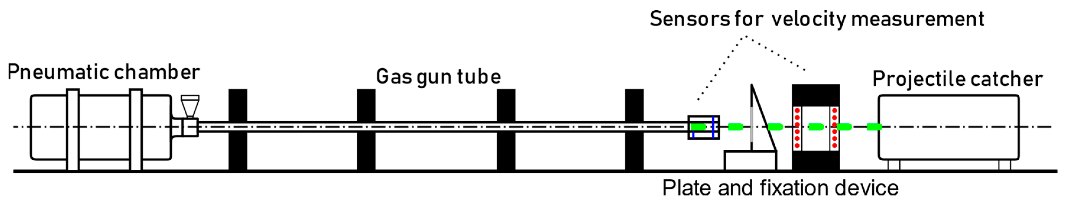
The experimental setup, used also in previous works of the authors [7,8,9], is depicted in Figure 1. It consists of a gas-gun to impel the projectile, two laser sensors to determine the impact and residual velocities of the projectile, a plate fixing system, and a projectile braking device. The velocity sensors have an accuracy of 1 m/s approx. The fixation system, Figure 2, allows the attachment of the contour of the plates 1.6 mm thickness Inconel 718 plates allowing an effective impact area of 100 × 100 mm2.
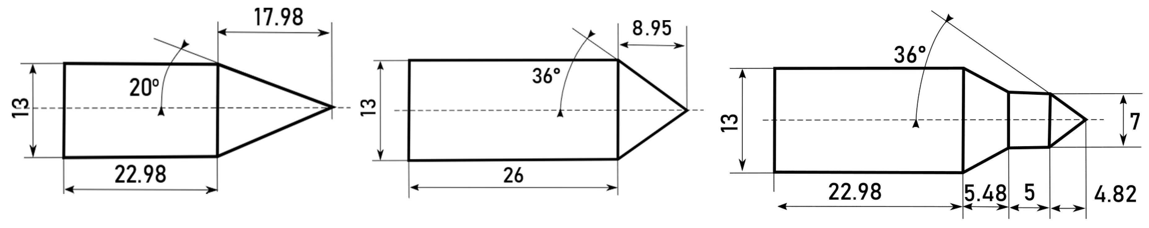
The used gas-gun barrel is approximately 13 mm and the projectiles have a similar diameter in order to avoid the use of sabots and to ensure the perpendicularity of the impact. The projectiles are made of high strength steel and heat treated in such a way that they are considered non-deformable projectiles since the yield stress is more than 1.5 GPa. Three different nose-shape projectiles have been used in this work: 40°, 72° and special double-ended geometry; and have been already studied in other works in the literature [14,15]. The geometry and dimensions of projectiles are illustrated in Figure 3. In order to ensure that the tests have equivalent impact energy, all projectiles have a mass close to 30 g.
Once the plates were impacted, local and global deformations were analyzed by means of a surface scanner (HP 3D Structured Light Scanner Pro S3, GRAFINTA, Madrid, Spain) with 0.05 mm maximum resolution. This device is based on two cameras that obtain the final geometry of the test and allow further measurement of the deflection of the tested plates.
2.3. Experimental Results
Experimental tests are analyzed in terms of ballistic curves, energy absorbed by the plate and local failure mechanisms for the three types of projectiles considered.
2.3.1. Ballistic Curves
The residual velocity, versus the impact velocity, , is showed in Figure 4 for the different projectiles analysed. The ballistic limits of the 72° nose projectile, is slightly greater than that corresponding to the 40° nose projectile, and the double-nose projectile . The experimental results, presented in Figure 4, have been fitted to the Lambert and Jonas [16] expression:
where is a fitting parameter. For the different analysed geometries, it was determined to be for 72° nose projectile, for 40° nose projectile, and for double-nose projectile.
2.3.2. Energy Absorbed by the Target
The mechanical energy absorbed by the specimen, , due to the impact of a projectile (mass Mp), can be calculated by the following expression:
The energy absorbed by the specimen versus impact velocity is presented in Figure 5. In the range of velocities analysed, the energy absorbed by the specimen impacted above the ballistic limit, is quite independent on the impact velocity.
2.3.3. Experimental Observations
The absorbed energy during the different nose-shaped projectile impact, is related to the different deformation and failure modes observed in Figure 6. In all cases, main failure mechanism was petalling, where the number of petals changed with velocity and projectile geometry. The relation between the failure-strain achieved and the stress-strain state induced by the projectile shape agrees with other author observations [14].
3. Numerical Simulations
3.1. Numerical Model Description
The impact problem presented were numerically modelled using the finite element commercial code ABAQUS 6.14/Explicit [17].
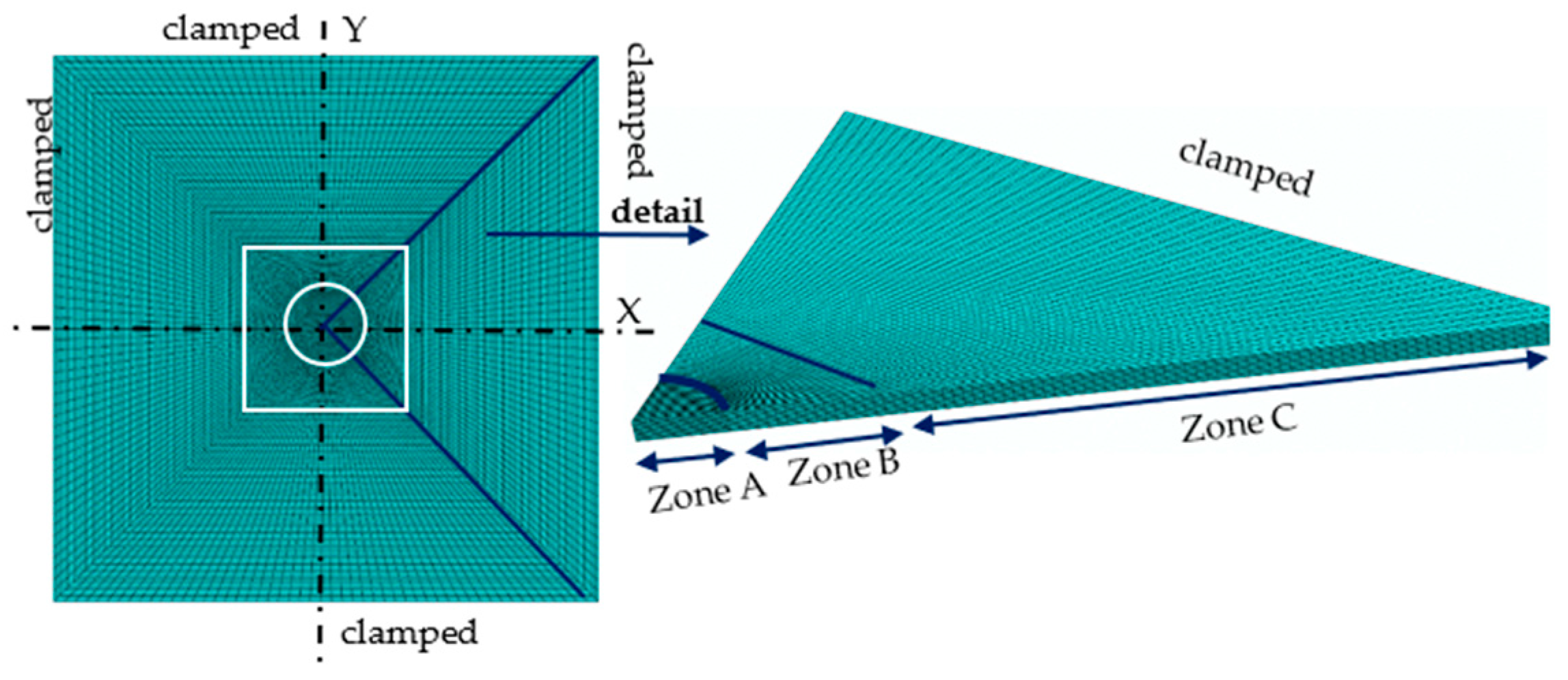
The mesh of the specimen, see Figure 7, has 264,100 nodes and 242,500 eight-node hexahedral elements with one integration point (C3D8R in ABAQUS notation) [17], distributed in three zones with different refinement:
- Zone A: the plate zone closes to the impact location. Requires the finest mesh, and its size is related to the radius of the projectile (34,900 elements).
- Zone B: is the transition region between the impact zone (zone A) and the surrounding zone (zone C) (44,500 elements).
- Zone C: represents a zone far from the impact point, where the boundary conditions are applied. It can be modelled with a coarse mesh (163,150 elements).
Following the recommendation of other authors [18], 12 elements were considered through the specimen thickness in the different zones.
Regarding the used projectiles, they are modelled according to the geometry presented in Figure 3. After impact tests, no plastic deformation was observed on the projectile, thus it is assumed to behave as a rigid body. This simplification reduces the computational cost required. In the contact between the projectile and the specimen, a friction coefficient of 0.1 is considered as proposed by other authors [8,18,19,20,21].
3.1.1. Mechanical Behavior of Inconel 718
The thermomechanical behavior of Inconel 718 at different strain rates and temperatures was described using the Johnson–Cook (JC) model [22]. This constitutive equation, Equation (3), consists of three independent terms accounting for the sensitivity to strain hardening due to plastic deformation, , (first term of the equation); the sensitivity to strain rate sensitivity, , (second term) and the sensitivity to temperature (third term).
where is a dimensionless parameter defined by the current temperature T, the melting temperature Tm, and a reference temperature T0 as:
Table 2 summarizes the values of the parameters described in Equations (2) and (3), see [23]. The initial temperature (T0) was defined as 20 °C and the melting temperature Tm as 1300 °C.
The process is assumed to be adiabatic due to the reduced time for heat transmission out of the generation zone. Taylor–Quinney coefficient (β), the percentage of plastic work converted into heat, is assumed to be equal to 0.9 [24,25,26]. The increase of temperature is given in Equation (5) depending also on the density of the material () and the specific heat at constant pressure ().
3.1.2. Failure Behavior of Inconel 718
The proposed failure behavior, based on [22], considers the dependence of the critical failure deformation on plastic strain , strain rate , temperature T, and stress triaxiality . The damage evolution parameter in an element, D, follows the next equation:
where D ranges from 0 (for an intact element) to 1 (for completely damaged element), is the increment of accumulated plastic strain in an integration cycle, and is the critical failure strain defined as:
being the failure constants for the material modelled. Table 3 shows the values used in this case.
3.2. Numerical and Experimental Data Comparison
The experimental ballistic curves are compared with the numerical predictions in Figure 8, showing good correlation. The ballistic limit is almost the same for experimental tests and for numerical simulations.
4. Discussion
This paper analyses the influence of different nose-shaped projectiles (40° conical, 72° conical, and double-nose conical) in the ballistic behavior of 1.6 mm thickness Inconel 718 plates. From the previous analysis developed, the following points can be remarked.
4.1. Ballistic Limit
The experiments presented show that the ballistic limit is strongly dependent on the configuration of the projectile nose-shape. This observation agrees with theoretical, numerical, and experimental conclusions achieved in other works [2,8,9,21].
Figure 9 shows the ballistic limit versus the projectile geometry. For the simple conical geometries, the ballistic limit increases with the nose angle of the projectile. This is generally observed in most metals although it has been shown that there may be exceptions due to the influence of the triaxiality and the Lode parameter on plasticity and failure strain [8,27,28].
For the case of 72°, the double-nose plays an important role because it reduces the perforation resistance of the plate by 10% ( for simple conical projectile and for double-nose projectile).
4.2. Perforation Mechanisms
The experimental permanent deflection of the specimen has been obtained from the use of a superficial scanner. Once scanned, the deflection in the middle plane of the plate has been obtained and compared with the numerical values. Figure 10 presents experimental and numerical post-mortem deflection in plates subjected to two impact velocities: one near the ballistic limit and the other far from ballistic (174 m/s). Note that the curve has been normalized according to the thickness in the Y axis and according to the length of the plate in the X axis. The following conclusions were obtained from this analysis:
- A greater projectile nose angle produces larger permanent deformations since more contact surface is involved.
- Numerical predictions follow the trend of experimental data. It is observed that at higher velocities, the damage is more localized, although numerically there are small differences. However, at low velocities, the model correctly predicts bending. Regarding the maximum deflection values, it is difficult to obtain that value due to the petalling effect.
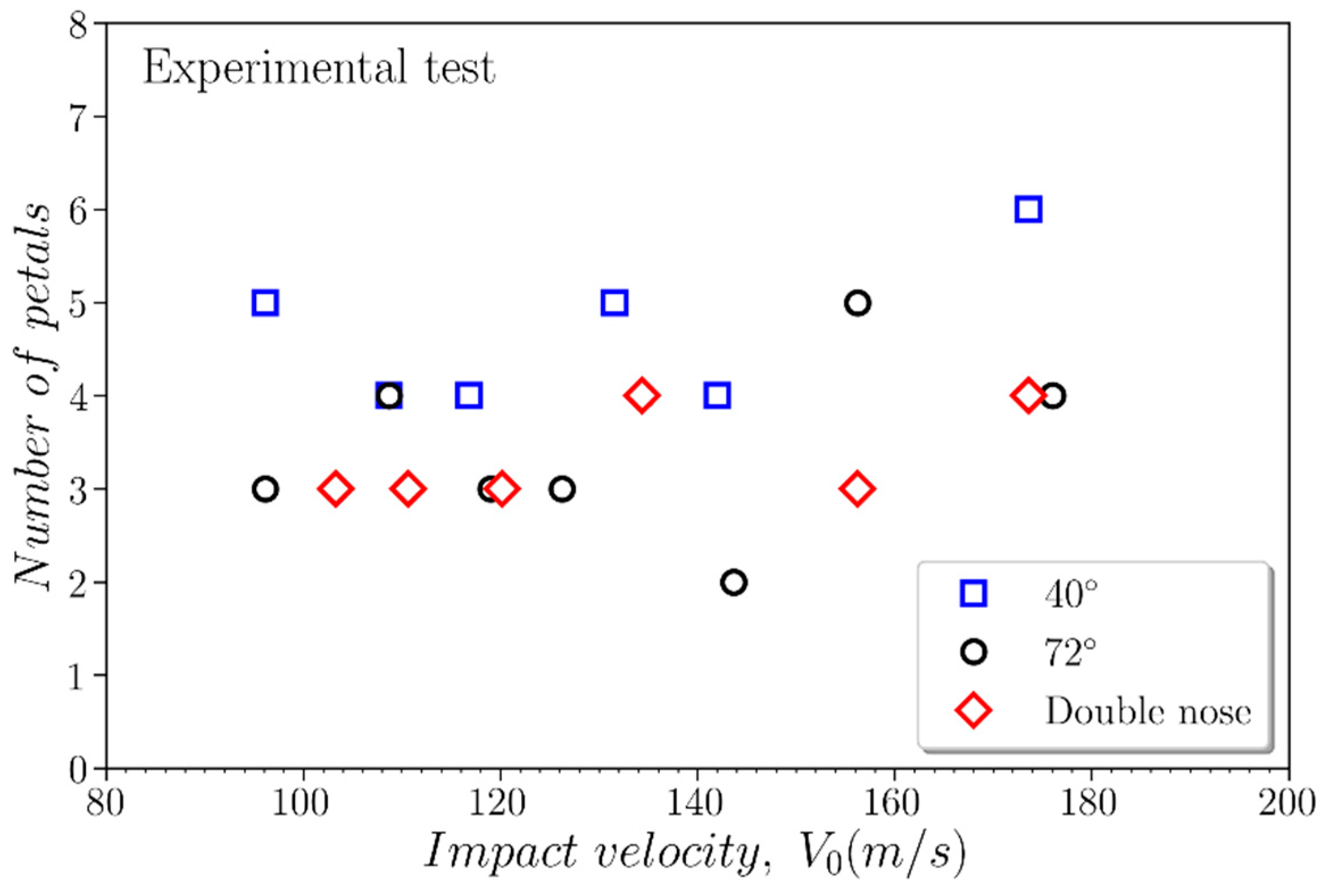
The number of petals is related to the nose-angle of the projectile, Figure 11. The lower the nose angle, the greater the number of petals for the range of impact velocities considered. However, the influence of the double nose is negligible compared to the 72° projectile. In addition, for all configurations studied, an increase in the number of petals with velocity is observed. This observation agrees with the results found by other researchers [14].
5. Conclusions
This paper analyses the influence of the projectile geometry (nose shape) on the ballistic performance of Inconel 718 plates from the experimental and numerical point. From the experimental testing, ballistic curves, failure mechanisms, and absorbed energy by the plate were determined at velocities up to 200 m/s for the different nose-shapes considered. It is found that the ballistic limit and the failure mode of the target are strongly dependent on the projectile nose shape. The projectile with the smallest nose angle is the most damaging (lower ballistic limit) and produces the least deflection and the greatest number of petals. The influence of the double-nose projectile results in reduced ballistic limit when compared to the single nose projectile and a similar deflection and number of petals.
On the other hand, the impact problem has been modelled by means of the finite element method implemented in ABAQUS/Explicit. The proposed model allowed one to calculate the ballistic curves for the different projectile geometries and to estimate the failure mode and global deflection of the specimen. The numerical results obtained were successfully compared with the experimental observations and the accuracy of the model was demonstrated.
Author Contributions
Conceptualization, M.R.-M., J.A.L., R.B., A.D.-Á., and M.H.M.; methodology, R.B. and J.A.L.; software, M.R.-M. and A.D.-Á.; validation, A.D.-Á. and M.R.-M.; formal analysis, J.A.L. and M.H.M.; writing—original draft preparation, M.R.-M., A.D.-Á., R.B., M.H.M., and J.A.L.; supervision J.A.L. and M.H.M.; funding acquisition, M.H.M.
Funding
This research was funded by the Ministry of Economy, Industry and Competitiveness and the FEDER program, grant number DPI2014-56137-C2-2-R.
Acknowledgments
The researchers are indebted to the FEDER/Ministerio de Ciencia, Innovación y Universidades de España (Project DPI2014-56137-C2-2-R) for the financial support which permitted to conduct part of this work.
Conflicts of Interest
The authors declare no conflict of interest.
References
- He, Q.; Xuan, H.; Liu, L.; Hong, W.; Wu, R. Perforation of aero-engine fan casing by a single rotating blade. Aerosp. Sci. Technol. 2013, 25, 234–241. [Google Scholar] [CrossRef]
- Børvik, T.; Clausen, A.H.; Eriksson, M.; Berstad, T.; Sture Hopperstad, O.; Langseth, M. Experimental and numerical study on the perforation of AA6005-T6 panels. Int. J. Impact Eng. 2005, 32, 35–64. [Google Scholar] [CrossRef]
- Borvik, T.; Hopperstad, O.S.; Berstad, T.; Langseth, M. Numerical simulation of plugging failure in ballistic penetration. Int. J. Solids Struct. 2001, 38, 6241–6264. [Google Scholar] [CrossRef]
- Borvik, T.; Dey, S.; Clausen, A.H. Perforation resistance of five different high-strength steel plates subjected to small-arms projectiles. Int. J. Impact Eng. 2009, 36, 948–964. [Google Scholar] [CrossRef]
- Senthil, K.; Arindam, B.; Iqbal, M.A.; Gupta, N.K. Ballistic Response of 2024 Aluminium Plates Against Blunt Nose Projectiles. Procedia Eng. 2017, 173, 363–368. [Google Scholar] [CrossRef]
- Gupta, N.K.; Iqbal, M.A.; Sekhon, G.S. Effect of projectile nose shape, impact velocity and target thickness on the deformation behavior of layered plates. Int. J. Impact Eng. 2008, 35, 37–60. [Google Scholar] [CrossRef]
- Rodríguez-Millán, M.; Vaz-Romero, A.; Rusinek, A.; Rodríguez-Martínez, J.A.; Arias, A. Experimental Study on the Perforation Process of 5754-H111 and 6082-T6 Aluminium Plates Subjected to Normal Impact by Conical, Hemispherical and Blunt Projectiles. Exp. Mech. 2014, 54, 729–742. [Google Scholar] [CrossRef] [Green Version]
- Rodriguez-Millan, M.; Garcia-Gonzalez, D.; Rusinek, A.; Arias, A. Influence of Stress State on the Mechanical Impact and Deformation Behaviors of Aluminum Alloys. Metals 2018, 8, 520. [Google Scholar] [CrossRef]
- Rodriguez-Millan, M.; Garcia-Gonzalez, D.; Rusinek, A.; Abed, F.; Arias, A. Perforation mechanics of 2024 aluminium protective plates subjected to impact by different nose shapes of projectiles. Thin Walled Struct. 2018, 123, 1–10. [Google Scholar] [CrossRef]
- Pereira, J.M.; Lerch, B.A. Effects of heat treatment on the ballistic impact properties of Inconel 718 for jet engine fan containment applications. Int. J. Impact Eng. 2001, 25, 715–733. [Google Scholar] [CrossRef] [Green Version]
- Di Sciuva, M.; Frola, C.; Salvano, S. Low and high velocity impact on Inconel 718 casting plates: Ballistic limit and numerical correlation. Int. J. Impact Eng. 2003, 28, 849–876. [Google Scholar] [CrossRef]
- Erice, B.; Pérez-Martín, M.J.; Gálvez, F. An experimental and numerical study of ductile failure under quasi-static and impact loadings of Inconel 718 nickel-base superalloy. Int. J. Impact Eng. 2014, 69, 11–24. [Google Scholar] [CrossRef] [Green Version]
- Reed, R.C. The Superalloys: Fundamentals and Applications; Cambridge University Press: Cambridge, UK, 2006; ISBN 9780521859042. [Google Scholar]
- Kpenyigba, K.M.; Jankowiak, T.; Rusinek, A.; Pesci, R. Influence of projectile shape on dynamic behavior of steel sheet subjected to impact and perforation. Thin Walled Struct. 2013, 65, 93–104. [Google Scholar] [CrossRef] [Green Version]
- Rodríguez Millán, M.; Moreno, C.E.; Marco, M.; Santiuste, C.; Miguélez, H. Numerical analysis of the ballistic behavior of Kevlar® composite under impact of double-nosed stepped cylindrical projectiles. J. Reinf. Plast. Compos. 2015, 35, 124–137. [Google Scholar] [CrossRef]
- Lambert, J.; Jonas, G.H. Towards Standardization of in Terminal Ballistic Testing: Velocity Representation; Rep. BRL-R-1852; Army Ballistic Research Laboratory: Aberdeen Proving Ground, MD, USA, 1976. [Google Scholar]
- Dassault Systèmes. Abaqus v6.14 Documentation—ABAQUS Analysis User’s Manual ABAQUS, 2014th ed.; Dassault Systemes: Velezzi vila kublai, France, 2014. [Google Scholar]
- Rodríguez-Martínez, J.A.; Rusinek, A.; Pesci, R.; Zaera, R. Experimental and numerical analysis of the martensitic transformation in AISI 304 steel sheets subjected to perforation by conical and hemispherical projectiles. Int. J. Solids Struct. 2013, 50, 339–351. [Google Scholar] [CrossRef] [Green Version]
- Børvik, T.; Langseth, M.; Hopperstad, O.S.S.; Malo, K.A.; Berstad, T. Perforation of 12 mm thick steel plates by 20 mm diameter projectiles with flat, hemispherical and conical noses Part II: numerical simulations. Int. J. Impact Eng. 2002, 27, 37–64. [Google Scholar] [CrossRef]
- Gupta, N.K.; Iqbal, M.A.; Sekhon, G.S. Experimental and numerical studies on the behavior of thin aluminum plates subjected to impact by blunt- and hemispherical-nosed projectiles. Int. J. Impact Eng. 2006, 32, 1921–1944. [Google Scholar] [CrossRef]
- Arias, A.; Rodríguez-Martínez, J.A.; Rusinek, A. Numerical simulations of impact behavior of thin steel plates subjected to cylindrical, conical and hemispherical non-deformable projectiles. Eng. Fract. Mech. 2008, 75, 1635–1656. [Google Scholar] [CrossRef]
- Johnson, G.R.; Cook, W.H. Fracture characteristics of three metals subjected to various strains, strain rates, temperatures and pressures. Eng. Fract. Mech. 1985, 21, 31–48. [Google Scholar] [CrossRef]
- Díaz-Álvarez, J.; Cantero, J.L.; Miguélez, H.; Soldani, X. Numerical analysis of thermomechanical phenomena influencing tool wear in finishing turning of Inconel 718. Int. J. Mech. Sci. 2014, 82, 161–169. [Google Scholar] [CrossRef]
- Jankowiak, T.; Rusinek, A.; Wood, P. A numerical analysis of the dynamic behavior of sheet steel perforated by a conical projectile under ballistic conditions. Finite Elem. Anal. Des. 2013, 65, 39–49. [Google Scholar] [CrossRef]
- García-González, D.; Rodríguez-Millán, M.; Vaz-Romero, A.; Arias, A. High impact velocity on multi-layered composite of polyether ether ketone and aluminium. Compos. Interfaces 2015, 22, 705–715. [Google Scholar] [CrossRef]
- Bendarma, A.; Jankowiak, T.; Łodygowski, T.; Rusinek, A.; Klósak, M. Experimental and numerical analysis of the aluminum alloy AW5005 behavior subjected to tension and perforation under dynamic loading. J. Theor. Appl. Mech. 2017, 55, 1219–1233. [Google Scholar] [CrossRef]
- Graham, S.M.; Zhang, T.; Gao, X.; Hayden, M. Development of a combined tension–torsion experiment for calibration of ductile fracture models under conditions of low triaxiality. Int. J. Mech. Sci. 2012, 54, 172–181. [Google Scholar] [CrossRef]
- Rodríguez-Millán, M.; Vaz-Romero, Á.; Arias, Á. Failure behavior of 2024-T3 aluminum under tension-torsion conditions. J. Mech. Sci. Technol. 2015, 29, 4657–4663. [Google Scholar] [CrossRef] [Green Version]
Figure 1.
Scheme of experimental setup.

Figure 2.
Geometry and dimensions of the target.
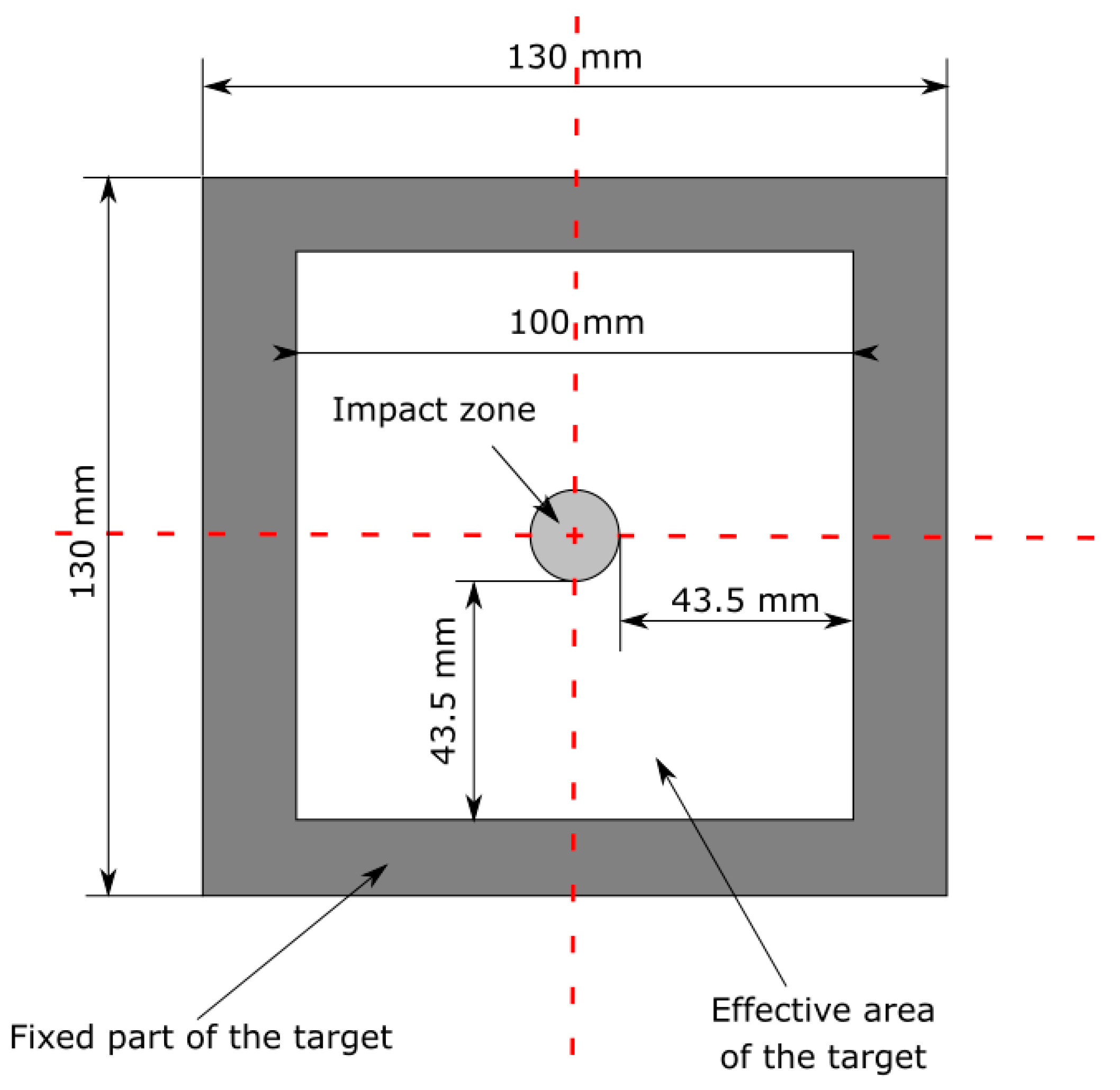
Figure 3.
Geometry of the considered projectiles (dimensions in mm).

Figure 4.
Residual velocity, , versus impact velocity, for the different projectiles.

Figure 5.
Energy absorbed by the specimen versus impact velocity .
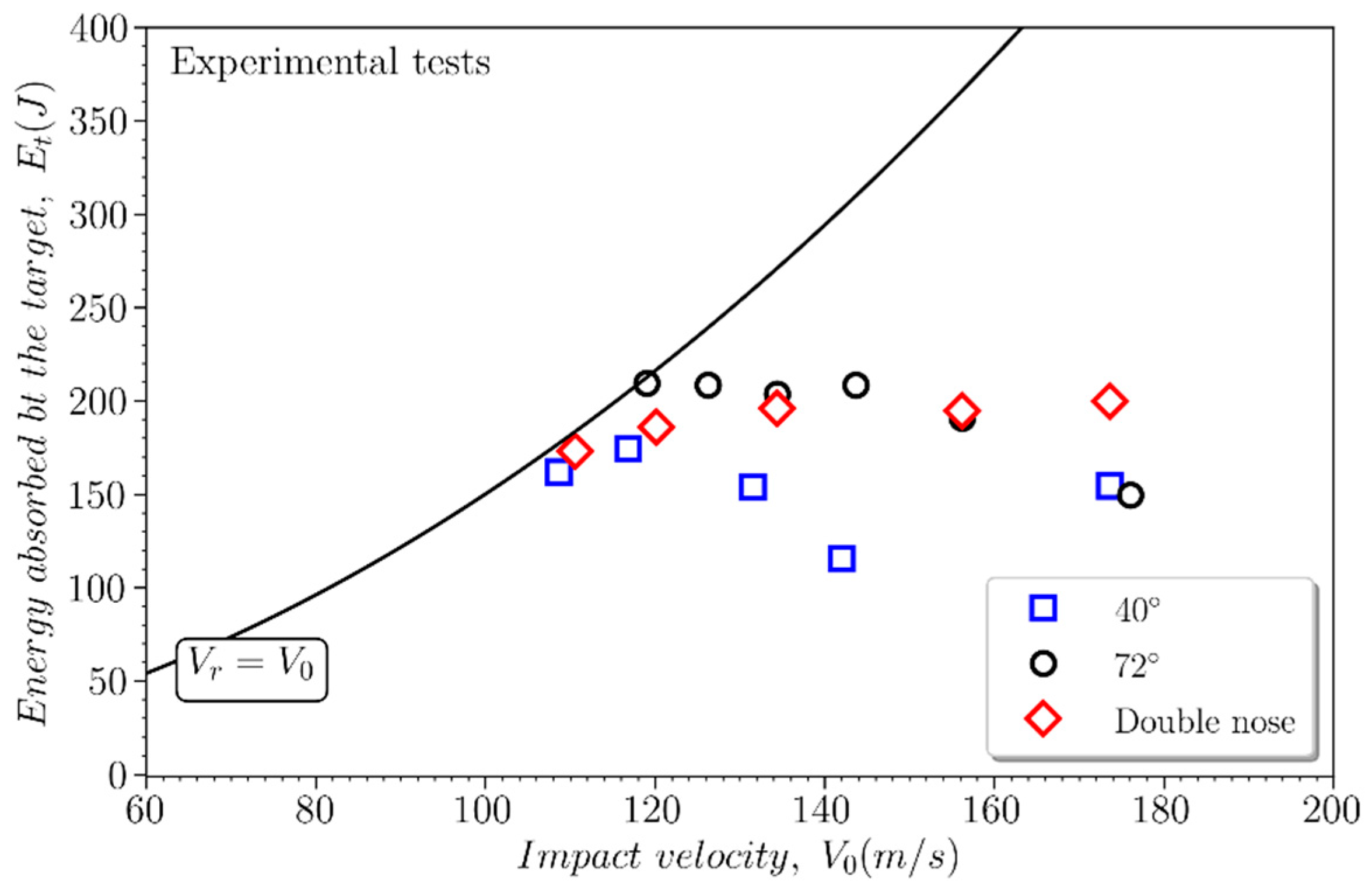
Figure 6.
Specimen final stage under different nose-shaped projectile impact.
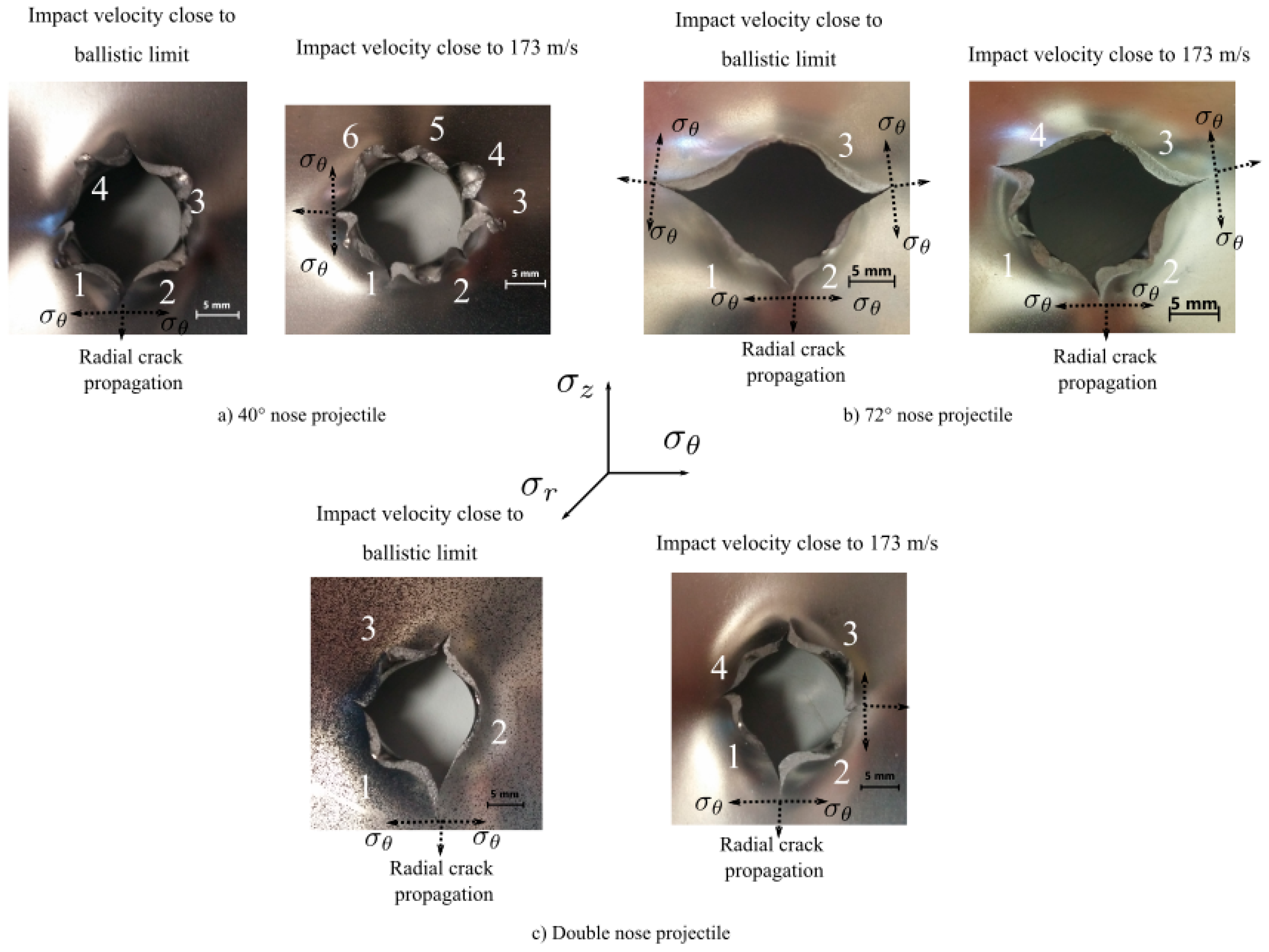
Figure 7.
Specimen mesh.

Figure 8.
Experimental and numerical ballistic curves for (a) 40° conical projectile, (b) 72° conical projectile, and (c) double-nose projectile.
Figure 8.
Experimental and numerical ballistic curves for (a) 40° conical projectile, (b) 72° conical projectile, and (c) double-nose projectile.
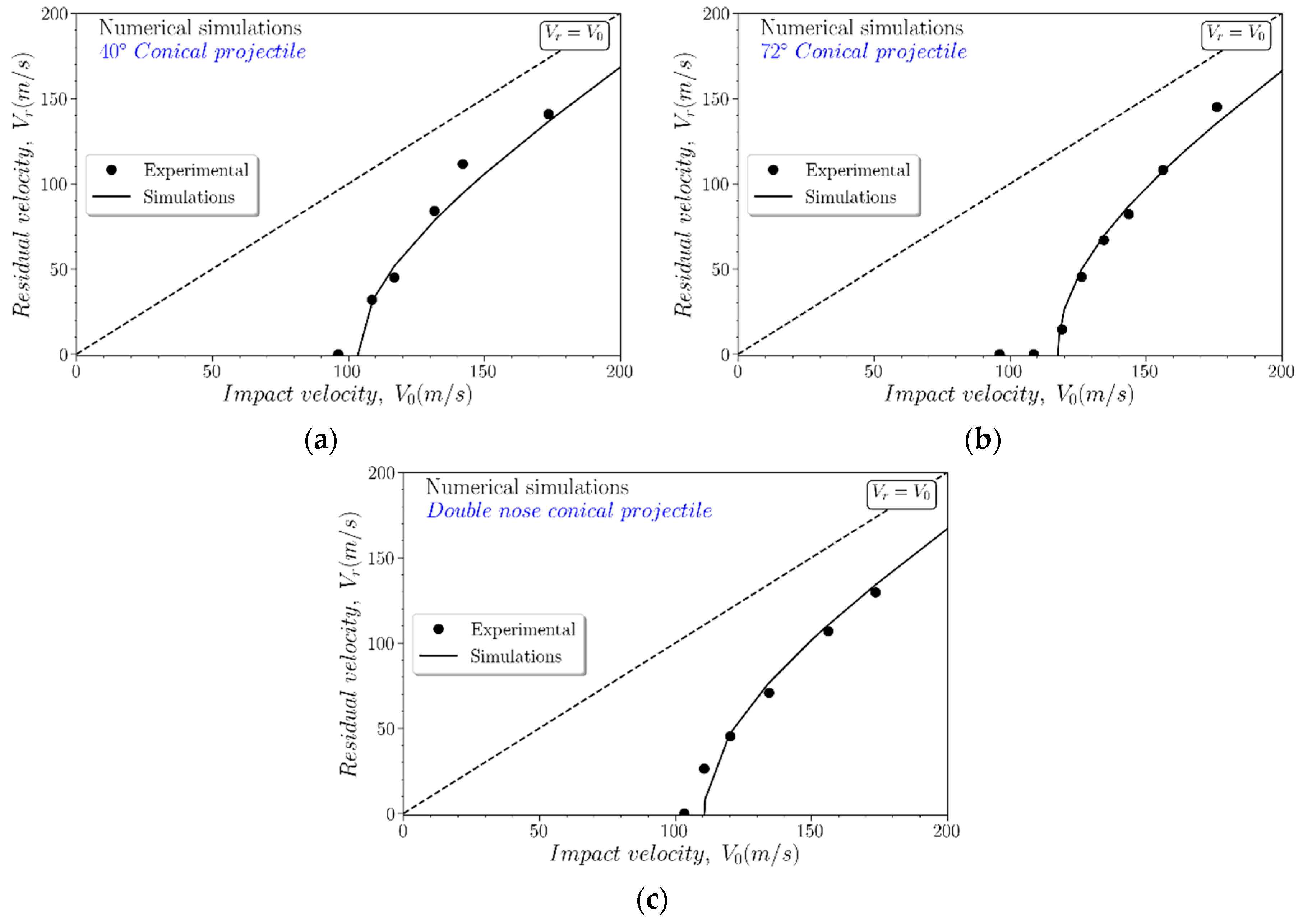
Figure 9.
Ballistic limit vs. the projectile geometry nose-angle.

Figure 10.
Dimensionless post-mortem deflection vs. the normalized target length for: (a) 40° conical projectile at V0 ∼ 96 m/s; (b) 40° conical projectile at V0 ∼ 174 m/s; (c) 72° conical projectile at V0 ∼ 108 m/s; (d) 72° conical projectile at V0 ∼ 174 m/s; (e) double-nose projectile at V0 ∼ 103 m/s; and (f) double-nose projectile at V0 ∼ 174 m/s.
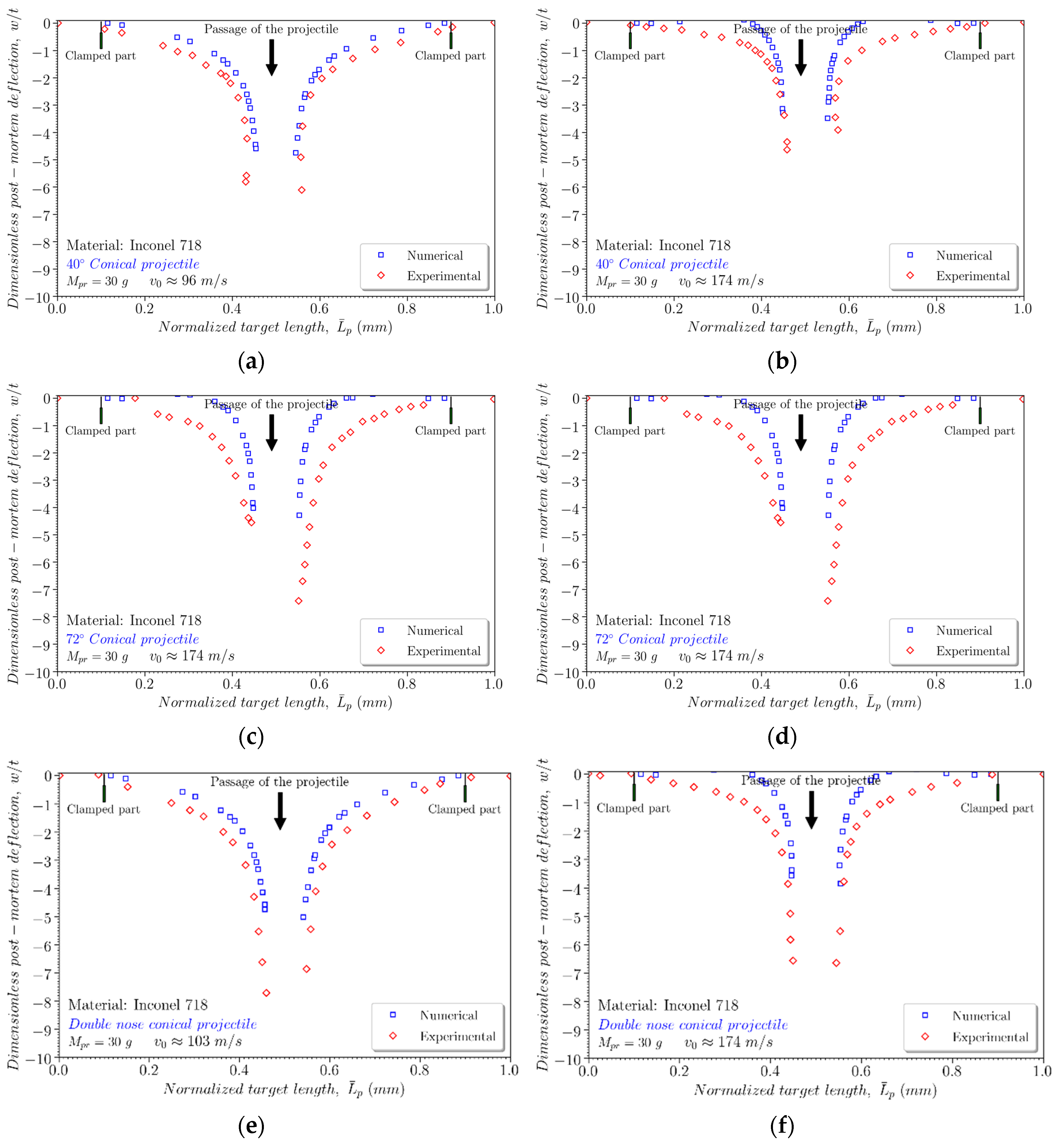
Figure 11.
Number of petals as a function of the impact velocity for 40° conical projectile, 72° conical projectile, and double-nose projectile.
Figure 11.
Number of petals as a function of the impact velocity for 40° conical projectile, 72° conical projectile, and double-nose projectile.


Table 1.
Chemical composition of the Inconel 718 (% of wt.) [13].
Table 1.
Chemical composition of the Inconel 718 (% of wt.) [13].
| Element | Ni | Cr | Fe | Nb | Mo | Ti | Al | Co | Si | Cu | Mn | C |
|---|---|---|---|---|---|---|---|---|---|---|---|---|
| % | 53.02 | 18.49 | 18.12 | 5.40 | 3.06 | 0.96 | 0.55 | 0.10 | 0.06 | 0.05 | 0.06 | 0.03 |
Table 2.
Properties of Inconel 718 and Johnson–Cook (JC) parameters obtained from [23].
Table 2.
Properties of Inconel 718 and Johnson–Cook (JC) parameters obtained from [23].
| Elasticity | Thermoviscoplastic Behaviour | ||||||
|---|---|---|---|---|---|---|---|
| 217 | 0.3 | 790 | 610 | 0.23 | 0.011 | 0.01 | 3.28 |
| Other physical constants | |||||||
| 8200 | 0.9 | 20 | 1300 | ||||
Table 3.
JC failure parameters for Inconel 718.
| Parameter | INCONEL 718 |
|---|---|
| 0.035 | |
| 0.65 | |
| −1.45 | |
| 0.04 | |
| 0.89 |
© 2019 by the authors. Licensee MDPI, Basel, Switzerland. This article is an open access article distributed under the terms and conditions of the Creative Commons Attribution (CC BY) license (http://creativecommons.org/licenses/by/4.0/).
Share and Cite
MDPI and ACS Style
Rodríguez-Millán, M.; Díaz-Álvarez, A.; Bernier, R.; Miguélez, M.H.; Loya, J.A. Experimental and Numerical Analysis of Conical Projectile Impact on Inconel 718 Plates. Metals 2019, 9, 638. https://doi.org/10.3390/met9060638
AMA Style
Rodríguez-Millán M, Díaz-Álvarez A, Bernier R, Miguélez MH, Loya JA. Experimental and Numerical Analysis of Conical Projectile Impact on Inconel 718 Plates. Metals. 2019; 9(6):638. https://doi.org/10.3390/met9060638
Chicago/Turabian StyleRodríguez-Millán, Marcos, Antonio Díaz-Álvarez, Richard Bernier, María Henar Miguélez, and José Antonio Loya. 2019. "Experimental and Numerical Analysis of Conical Projectile Impact on Inconel 718 Plates" Metals 9, no. 6: 638. https://doi.org/10.3390/met9060638
Note that from the first issue of 2016, this journal uses article numbers instead of page numbers. See further details here.