Biodegradable Implantation Material: Mechanical Properties and Surface Corrosion Mechanism of Mg-1Ca-0.5Zr Alloy


Department of Materials Science and Engineering, National Cheng Kung University, Tainan 701, Taiwan
*
Author to whom correspondence should be addressed.
Metals 2019, 9(8), 857; https://doi.org/10.3390/met9080857
Submission received: 19 June 2019
/
Revised: 24 July 2019
/
Accepted: 2 August 2019
/
Published: 6 August 2019
(This article belongs to the Special Issue Failure Analysis of Biometals)
Abstract
:Mg alloy is suitable for biomedical implants as the mechanical properties of Mg are close to those of human bone. Ca is a major element in bone and Zr has a great grain refinement effect. Hence, we developed Mg-1Ca-0.5Zr alloy (XK105) as a biodegradable biomaterial and investigated its mechanical properties and surface corrosion mechanism. The results showed that heat treatment made the secondary phase homogeneous. Tensile tests showed that the heat treatment increased ductility, and that the tensile stress results in the extrusion direction showed better ductility than that in the transverse direction because of the fiber texture and extrusion characteristics. Electrochemistry test results showed that XK105 after heat treatment had a lower corrosion rate than that before heat treatment and that of pure Mg. XK105 after heat treatment formed a calcium phosphate layer after immersion in simulated body fluid; this layer protects Mg from corrosion. Surface roughening treatment increased corrosion because pits on the surface promoted pitting corrosion. This study developed Mg-1Ca-0.5Zr alloy as a biomedical implant material. The results can be used as a reference for the biomedical material industry.
1. Introduction
Common biomedical implant materials include metals, polymers, and ceramics. Metal-based biomedical materials have better mechanical properties than those of polymers and ceramics [1] and are thus much more widely used in practical applications. Common metal-based biomedical materials such as stainless steel [2], Ti alloys [3], and Co-based alloys [4] have elastic moduli that are very different from that of human bone. This leads to a stress shielding effect, which makes new bone tissues lack stimulation during growth and leads to insufficient recovery of bone strength [5]. Another disadvantage of common metal-based biomedical materials is their non-degradability [6]; they must be removed in a second operation after the affected area has recovered.
In view of these issues, Mg alloys have been developed as next-generation biomedical materials [7]. Mg alloys have several advantages as biomaterials. Mg is an essential mineral nutrient, so it has good biosafety [8]. Mg alloys have biomechanical properties similar to those of human bone, which can avoid stress shielding effects and improve the strength of bone tissue after healing [9]. Mg is degradable in vivo, and when used for short-term implants, it does not need to be removed in a second operation [10]. The products produced by the degradation of Mg in vivo can be excreted through the kidney [11]. Mg alloy combines well with surrounding bone tissues after degradation and accelerates the formation of biological calcium phosphate [12]. Mg alloys can stimulate the differentiation and growth of osteoblasts and promote bone tissue production [13].
The concentration of chloride ions in the human body is as high as 150 mmol/L, making the degradation of pure Mg very fast [14]. Such a fast degradation rate may cause slow recovery of the affected area and even lead to tissue necrosis [15]. Adding other metallic elements to form Mg alloys can solve this issue. Mg-Ca alloys have become a focus in the development of Mg-based biomedical materials [16] because Ca is not only harmless to the human body, but also an important component that makes up bone [17]. The Ca ions released during degradation help the healing of bone tissue [18]. Adding Ca to Mg alloys can enhance their mechanical properties through grain refinement and solid solution strengthening [19]. However, if the Ca content is excessive, a large amount of Mg2Ca will be precipitated, decreasing mechanical properties and corrosion resistance [20]. Mg2Ca has a lower corrosion potential than that of the Mg base, so it is preferentially corroded as a sacrificial anode and can thus increase the corrosion resistance of the Mg base [21]. However, in excess amounts, Mg2Ca forms a continuous network structure at the grain boundary, causing cracks [22]. According to previous studies, Mg alloy with 1 wt.% Ca has good mechanical properties and corrosion resistance [23]. Both Zr and Mg are hexagonal close-packed (HCP) structures and the two elements have very similar lattice constants, so adding Zr to Mg alloy can refine grains and improve mechanical properties [24,25]. However, in excess amounts, Zr aggregates into particles larger than 5 μm and reduces the corrosion resistance of Mg alloys [26]. The casting Mg-Ca-Zr alloy has better tensile strength and elongation than Mg-Ca alloy at all Ca content ratios [27]. Heat treatment is important for Mg alloys in application. The temperature of post heat treatment is generally around 380–420 °C for 6–12 h [28,29] to achieve the best mechanical properties. For a novel Mg alloy, the heat treatment conditions should be suggested in this range.
In this study, the Mg alloy Mg-1Ca-0.5Zr (98.5 wt.% Mg, 1 wt.% Ca, and 0.5 wt.% Zr) is subjected to heat treatment to homogenize and stabilize its material properties. The heat treatment condition was 400 °C for 8 h at atmosphere which followed the common condition of Mg-Ca alloy [28]. A series of experiments were conducted to evaluate the feasibility of Mg-1Ca-0.5Zr alloy as a biomedical implant material. The results can be used as a reference for the biomedical material industry.
2. Material and Methods
Mg-1Ca-0.5Zr was produced in a smelting furnace. A 99.9 wt.% pure Mg block was placed in a stainless-steel bowl and heated to 700 °C until the Mg block had completely melted into a liquid state. Then, Mg-20Ca and Mg-33Zr blocks were placed into the molten Mg. After the alloy blocks had melted completely, the molten alloy was poured into a mold and allowed to cool in air to room temperature. For all casting, argon was used as a protective gas. The casting product, Mg-1Ca-0.5Zr alloy, is denoted as XK105 following the ASTM (American Society for Testing and Materials) naming convention. For experiments, we processed XK105 into an extruded sheet, denoted as XK105-F. To enhance the mechanical properties, XK105 was subjected to heat treatment at 400 °C for 8 h in an air furnace. To decrease the formation of the crystalline phase, the alloy was water-quenched after heat treatment. The heat-treated XK105 is denoted XK105-H.
For microstructural observation, epoxy was used to cold-mount and embed XK105-F and XK105- H. The samples were then polished using 1 and 0.3 μm aluminum oxide powder. After polishing, the samples were corroded using a solution of 4.2 g of picric acid, 10 mL of acetic acid, and 90 mL of ethanol. The microstructure was observed using light microscopy (LM) (ZEISS, Oberkochen, Germany) and scanning electron microscopy (SEM) (HITACHI, Tokyo, Japan). Energy-dispersive X-ray spectrometry (EDS) was used for elemental composition semi-quantitative analysis.
This study used tensile tests to determine the tensile strength of the extruded profiles of XK105 and the mechanical properties after heat treatment. Three specimens of XK105-F were taken along the extrusion direction (ED) and the transverse direction (TD). After the samples were cut to an appropriate size, they were punched into a fixed size using a punch press. A stretching test was conducted with an initial strain rate of 8.3 × 10⁻⁴ s−1 at room temperature. We used SEM and EDS to investigate the stretch-breaking behavior.
An erosion wear test was conducted using XK105-F and XK105-H. A particle spray tester (Chun Yen Testing Machines Co., Taichung, Taiwan) was used for erosion wear and surface roughening. The environmental conditions in the erosion wear test were room temperature and a relative humidity of 50% to 70%. The erosion particles were Al2O3 (average diameter: 150 μm) and SiO2 (average diameter: 295 μm), and the erosion angle was 15° to 90°. The particle rate of erosion was 1.2 g/s, and the pressure was set to 3 kg/cm2 (0.29 MPa). The average jet rate of Al2O3 was calculated as 73 m/s, and that of SiO2 was 66 m/s. Surface roughening treatment was conducted at erosion angles of 15°, 45°, and 90°. After surface roughening, the samples were observed using LM and SEM.
A potentiodynamic polarization test was conducted using pure Mg, XK105-F, and XK105-H samples. In the test, a three-electrode system was used to obtain the polarization curve. The reference electrode was a saturated calomel electrode (SCE), the salt bridge was saturated KCl solution, and the auxiliary electrode was a platinum electrode. The specimens were embedded in epoxy resin and then carefully ground. The employed electrolyte was a revised simulated body fluid (R-SBF) solution [30], which has ion composition and concentration similar to those of human blood plasma. The scan rate in the polarization test was 1 mV/s, from −2.2 to −1.2 V, and a constant temperature of 37 °C was used. The polarization curve has a linear Tafel region around the corrosion potential. The corrosion current can be obtained from the anodization curves using the extrapolation method.
The immersion test was used to evaluate the corrosion rate. The corrosion rate was calculated as:
where m1 is the mass after immersion, m0 is the mass before immersion, A is the total surface area of the sample, and T is the immersion time. The immersion solution was R-SBF. XK105-H and surface- roughened XK105-H sampled were immersed in R-SBF for 1, 3, and 7 days at a constant temperature of 37 °C.
3. Results and Discussion
3.1. Metallographic Analysis
Figure 1a,b respectively show metallographic images of XK105-F and XK105-H observed using LM. Crystal phases appear along ED for XK105-F. The crystal phases of XK105-H were not along ED. This indicates that heat treatment made the crystal phases dissolve into the matrix, homogenizing the material. The grains were subjected to dynamic recrystallization during extrusion, and thus isometric crystals formed. The calculated average grain sizes of XK105-F and XK105-H were 14.2 and 17.1 μm, respectively.
SEM observation was conducted to verify the secondary phases of XK105. A Ca-rich crystal phase can be seen in Figure 2a; the phase was identified as Mg2Ca [31]. Most of the Mg2Ca phase was along ED. A Zr-rich phase can be seen in Figure 2b; the phase was identified as pure Zr particles which accumulated at grains [32].
3.2. Tensile Properties and Fracture Morphology
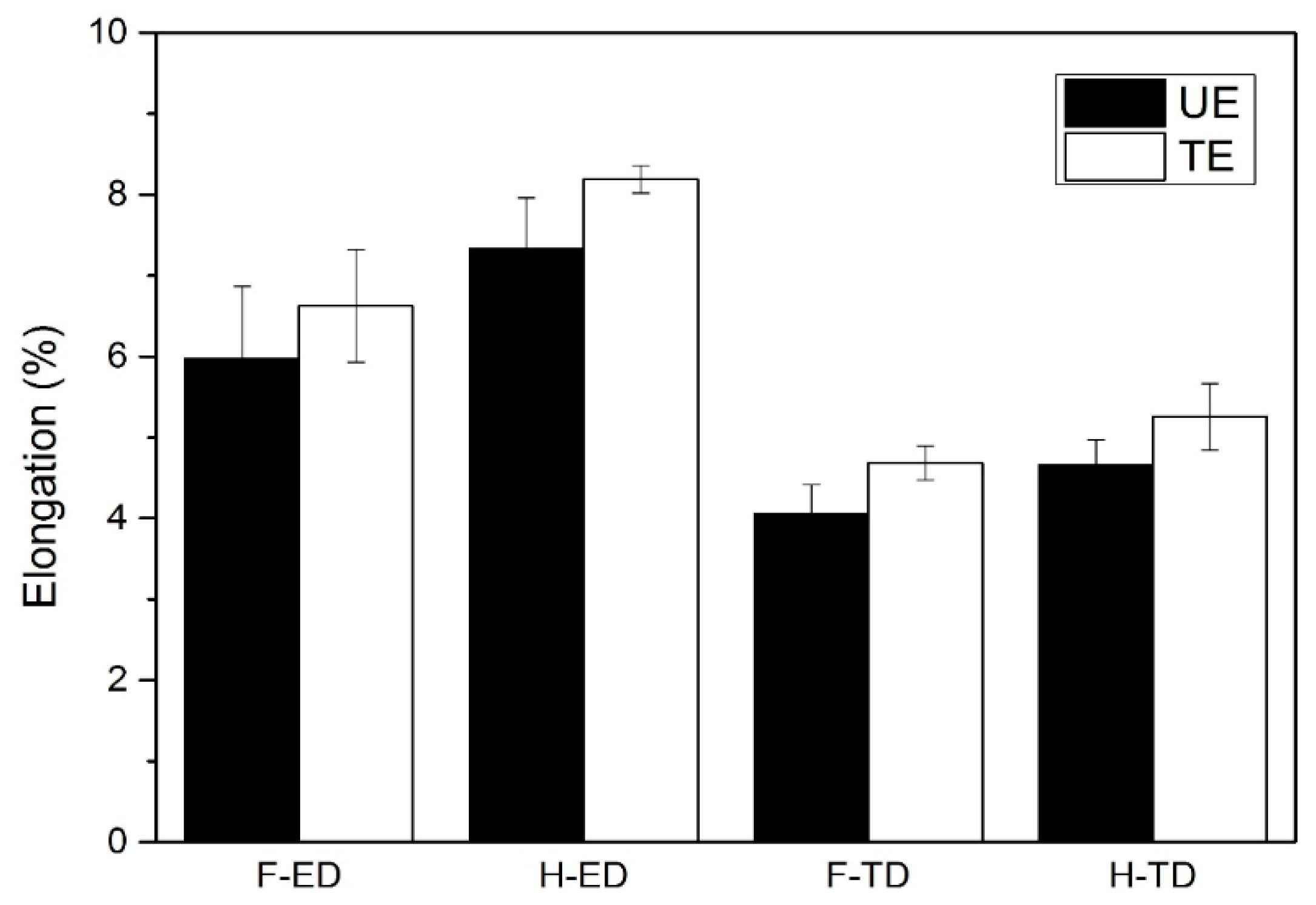
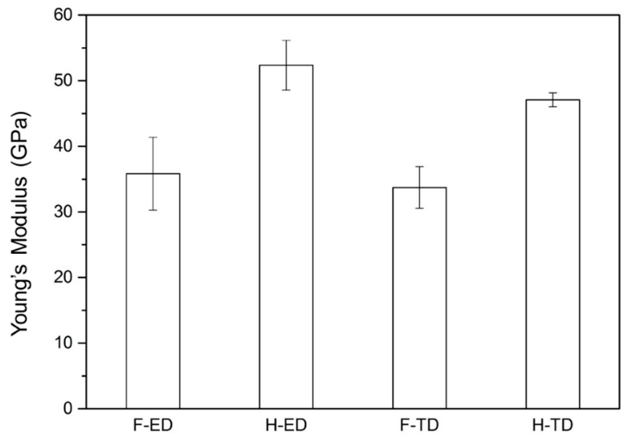
Figure 3 and Figure 4 respectively show the tensile stress-strain curve and tensile stress of XK105. The tensile stress of XK105-F along TD is about 220 MPa. According to reference [33], the tensile stress along TD of pure Mg was 173 MPa, and which of Mg-0.1Ca was 180 MPa. The tensile stress of human bone is about 150 MPa. XK105 thus has sufficient tensile strength to apply to stress load in the human body. The yield stress of XK105-F along TD was about 180 MPa, which of pure Mg was 103 MPa and which of Mg-0.1Ca was 92 MPa [33]. The results showed the adding Zr can improve the tensile strength effectively. Figure 5 shows the elongation of XK105. The elongation was about 4–8% and was caused by the addition of Ca [34]. Elongation increased after heat treatment because of the homogenization of textures and the solid solution of the secondary phases. Figure 6 shows the Young’s modulus of XK105. The value is about 35–55 GPa; it increased after heat treatment because the Ca atoms dissolved into the matrix and changed the lattice. Although the Young’s modulus of XK105 is much higher than that of human bone (3–20 GPa), it has greater similarity compared to other medical implant materials. The tensile strength along TD is higher than that along ED. The XRD pattern (Figure 7) shows that the mean peak along ED was (). This is due to the HCP crystals slipping along ED, which led to a small angle between the (0001) plane and ED. When the tensile strength transferred toward ED, the dislocations more easily slipped compared to that toward TD. Therefore, the elongation of XK105 along ED was higher but the tensile stress was lower compared to those along TD.
Figure 8a,b shows the tensile fracture morphology of XK105-H on the ED plane. Dimples can be observed on the fracture surface. Mg2Ca, which did not dissolve into the matrix, appears inside the dimples. Figure 8c,d shows the tensile fracture morphology of XK105-H on the TD plane. Thin wall structures can be observed. These structures are cleavages of brittle failure.
3.3. Fracture Toughness
Medical implants easily deform when subjected to a stress impact. The fracture toughness of XK105 is thus an important property. Figure 9 shows the fracture toughness of XK105. The fracture toughness was lower when the stress was applied toward TD. There is a non-plane strain of XK105, and it showed that the thickness of material was not thick enough to fracture as a plane strain. LM observations indicate that the fracture cracks had more bending along ED than TD, as shown in Figure 10a,c. The cracks thus required more energy to spread, so the toughness of the sample along ED was higher than that along TD. Figure 10b,d show the fracture surface of XK105-H. A smoother fracture surface, which resulted from brittle fracture on the TD plane, can be observed. Therefore, toughness on the TD plane was lower than that on the ED plane. Figure 11 shows the secondary surface morphology and fracture mechanism. The end of the crack on the ED plane has a branch morphology; the branching of that on the TD plane is not obvious. This was caused by the brittle secondary phase easily cracking when subjected to stress; the cracks spread along TD while tensile stress was applied along ED. The density of the secondary phase was thus lower on the crack-spreading path. Therefore, the cracks on the ED plane easily branched and had much longer spreading paths than those of cracks on the TD plane.
3.4. Erosion Properties and Surface Roughness
Figure 12 shows the relationship between erosion rate and erosion angle. For both Al2O3 or SiO2, the angle for the highest erosion rate changed from 45° to 30° after heat treatment. This shows that XK105 had lower hardness and higher ductility after heat treatment. The erosion rate obtained with Al2O3 particles was higher than that obtained with SiO2 due to the higher hardness of Al2O3.
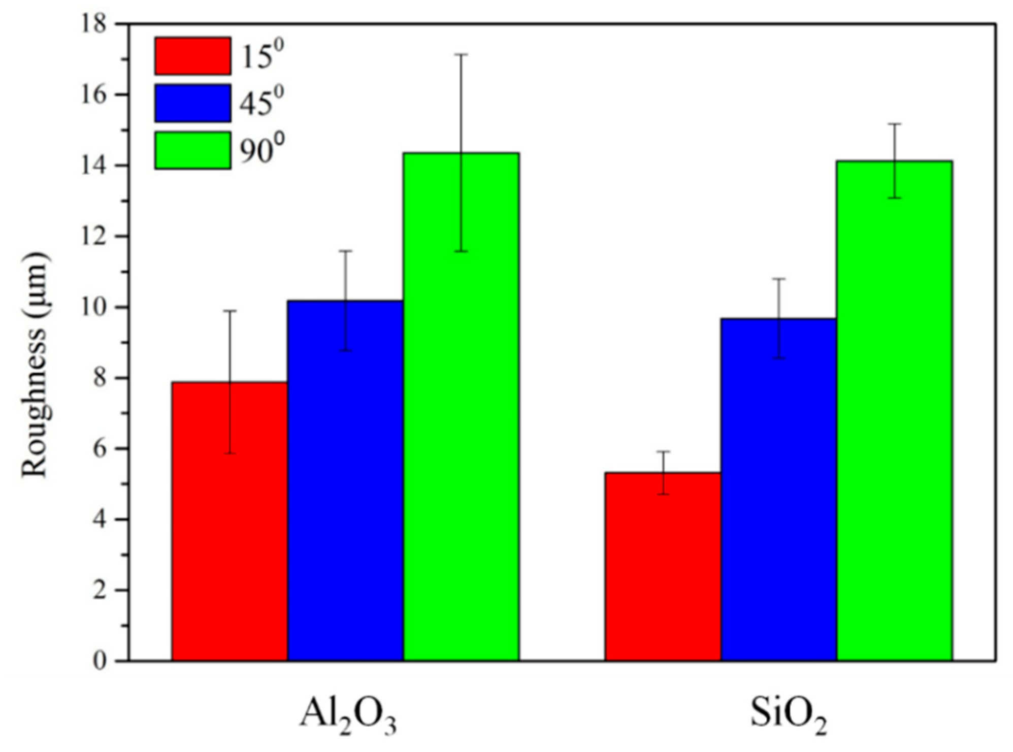
Figure 13 shows the surface roughness after the erosion test. The roughness obtained with Al2O3 and SiO2 was similar. The highest and lowest roughness was obtained with erosion angles of 90° and 15°, respectively. The measurement of these erosion properties could be applied to later experiments to clarify the relationship between anti-corrosion ability and surface roughness. This will have a benefit of increasing the bioreactivity for medical applications.
3.5. Potentiodynamic Polarization Test
The potentiodynamic polarization test was used to analyze the corrosion rate of XK105 in simulated body fluid. Surface roughening treatment can effectively increase cell adhesion [35]. Therefore, in this study, surface roughen treatment using the particle erosion wear method was applied. The potentiodynamic polarization test was conducted to determine anti-corrosion ability. The electrochemical properties of XK105 calculated from the potentiodynamic polarization test results are shown in Table 1. The results show that heat treatment improved the anti-corrosion property of XK105, making it better than that of pure Mg. This was due to Mg2Ca being dissolved into the matrix during heat treatment, and the effect of galvanic corrosion becoming inactive, which reduced the corrosion current and potential. The potentiodynamic polarization curve is shown in Figure 14. The reduction rate of XK105-F is lower than that of pure Mg. XK105-H had the lowest reduction rate. The low reduction rate represents the low formation rate of H2, which is harmless to the human body. The curves of XK105-F and XK105-H show passivation at a corrosion potential of less than −1.5 V. Passivation was caused by the added Ca, which formed a stable passivation layer to restrain the corrosion compared to pure Mg [36].
For surface roughening, 90° SiO2 erosion created higher roughness. The electrochemical properties of surface-roughened XK105 are shown in Table 2. The corrosion current was higher after surface roughening treatment. The surface roughening increased the surface area of the material, increasing the corrosion rate [37]. The surface-roughened XK105 did not show passivation around −1.5 V in the potentiodynamic polarization curve because the rough surface made the passivation layer easily peel off after formation.
3.6. Immersion Test
To understand the surface corrosion mechanism and quantify the corrosion rate of materials, this study subjected XK105-H and surface-roughened XK105 to an immersion test. The results of the immersion test are shown in Figure 15. The corrosion rate after surface roughening treatment increased greatly, and the corrosion rate of XK105-H was lower than that of pure Mg. The corrosion rate of XK105-H after three days decreased and became stable. This was due to the formation of a surface passivation layer, which restrained the corrosion effect. The phenomenon in which the corrosion rate decreased after three days of surface-roughened XK105 was not obvious relatively, because it did not have a passivation layer.
Figure 16 shows the secondary surface of XK105-H and surface-roughened XK105 during the immersion test. XK105-H maintained the integrity of its macroscopic morphology, whereas the surface- roughened XK105 showed pitting corrosion after one day of immersion. The main corrosion mechanism of Mg alloy was pitting corrosion when immersed in R-SBF [30]. The surface roughening treatment created a lot of pits on the surface of the material. These pits promoted pitting corrosion, and thus weight loss due to corrosion was observed on the 7th day of immersion.
In Figure 17a, a calcium phosphate layer can be observed on the XK105-H surface after immersion. This layer protected the material against corrosion. Calcium phosphate is the main component of human bone, so this layer could help heal the affected area [38]. In contrast, there was a thick cover layer on the surface of the surface-roughened XK105, as shown in Figure 17b. The cover compound was Mg hydroxide which does not have a healing effect. The formation of calcium phosphate requires a suitable hydroxide ion group to react with [39]. The degradation rate of surface- roughened XK105 was too fast for calcium phosphate to form; instead, Mg hydroxide formed.
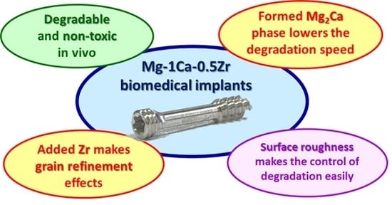
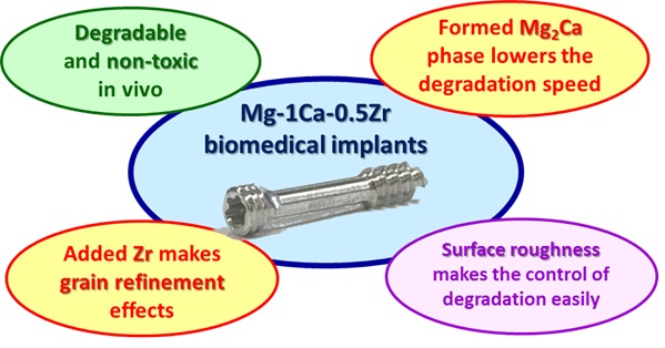
To summarize the above results, Mg-1Ca-0.5Zr biomedical alloy has a suitable degradation rate and good mechanical strength. The surface roughness can help control the degradation rate. Mg-1Ca-0.5Zr can thus be applied for biomedical implants. A summary is shown in Figure 18.
4. Conclusions
- (1)
- The brittle Mg2Ca phase of the XK105 solid dissolved into the matrix after heat treatment. This made the texture uniform and increased both elongation and fracture toughness. The Young’s modulus of XK105 increased after heat treatment because of the solid solution of Ca atoms.
- (2)
- The TD plane of XK105 had higher strength but lower elongation than those of the ED plane because of the texture effects in which the grain slip was hard to start up on the ED plane. The fracture toughness along ED was better than that along TD because the crack-spreading direction was parallel to the arrangement direction of the secondary phase.
- (3)
- The heat treatment of XK105 reduced galvanic corrosion due to the solid solution, and further improved anti-corrosion ability. The surface-roughened XK105 had a larger surface area, which enhanced the corrosion reaction.
- (4)
- A calcium phosphate layer formed during corrosion on the XK105-H surface, significantly reducing the corrosion rate. The surface-roughened XK105 formed magnesium hydroxide instead because of its faster corrosion rate. The magnesium hydroxide did not provide a protective effect.
- (5)
- This study developed a biomedical implant material, Mg-1Ca-0.5Zr alloy. The results can be used as a reference for the biomedical material industry.
Author Contributions
Y.-T.C.: conceived and designed the analysis, collected the data, performed the analysis, wrote the paper. F.-Y.H.: conceived and designed the analysis, contributed data and analysis tools, performed the analysis, revised the paper. J.-C.S.: collected the data, performed the analysis, wrote the paper.
Funding
The authors are grateful to the Instrument Center of National Cheng Kung University and the Ministry of Science and Technology of the Republic of China (MOST 107-2221-E-006-012-MY2) for their financial support.
Conflicts of Interest
The authors declare no conflicts of interest.
References
- Staiger, M.P.; Pietak, A.M.; Huadmai, J.; Dias, G. Magnesium and its alloys as orthopedic biomaterials: A review. Biomaterials 2006, 27, 1728–1734. [Google Scholar] [CrossRef] [PubMed]
- Dikici, B.; Topuz, M. Production of annealed cold-Sprayed 316L stainless steel coatings for biomedical applications and their in-vitro corrosion response. Prot. Met. Phys. Chem. Surf. 2018, 54, 333–339. [Google Scholar] [CrossRef]
- Yadroitsev, I.; Karkhmalev, P.; Yadroitsava, I.; Du Plessis, A. Qualification of Ti6Al4V ELI alloy produced by laser powder bed fusion for biomedical applications. JOM 2018, 70, 372–377. [Google Scholar] [CrossRef]
- Chen, Q.Z.; Thouas, G.A. Metallic implant biomaterials. Mater. Sci. Eng. R Rep. 2015, 87, 1–57. [Google Scholar] [CrossRef]
- Chien, C.; Liao, T.Y.; Hong, T.F.; Kuo, T.Y.; Chang, C.H.; Yeh, M.L.; Lee, T.M. Surface microstructure and bioactivity of hydroxyapatite and fluorapatite coatings deposited on Ti-6Al-4V substrates using Nd-YAG Laser. J. Med. Biol. Eng. 2014, 34, 109–115. [Google Scholar] [CrossRef]
- Hench, L.L.; Polak, J.M. Third-generation biomedical materials. Science 2002, 295, 1014–1017. [Google Scholar] [CrossRef] [PubMed]
- Kojima, Y. Platform science and technology for advanced magnesium alloys. Mater. Sci. Forum 2000, 350, 3–18. [Google Scholar] [CrossRef]
- Musso, C.G. Magnesium metabolism in health and disease. Int. Urol. Nephrol. 2009, 41, 357–362. [Google Scholar] [CrossRef]
- Nagels, J.; Stokdijk, M.; Rozing, P.M. Stress shielding and bone resorption in shoulder. J. Shoulder Elb. Surg. 2003, 12, 35–39. [Google Scholar] [CrossRef]
- Jurgen, V. Magnesium: Nutrition and metabolism. Mol. Asp. Med. 2003, 24, 27–37. [Google Scholar] [CrossRef]
- Lin, D.J.; Hung, F.Y.; Jakfar, S.; Yeh, M.L. Tailored coating chemistry and interfacial properties for construction of bioactive ceramic coatings on magnesium biomaterial. Mater. Des. 2016, 89, 235–244. [Google Scholar] [CrossRef]
- Witte, F.; Kaese, V.; Haferkamp, H.; Switzer, E.; Meyer-Lindenberg, A.; Wirth, C.J.; Windhagen, H. In vivo corrosion of four magnesium alloys and the associated bone response. Biomaterials 2005, 26, 3557–3563. [Google Scholar] [CrossRef] [PubMed]
- Pietak, A.; Mahoney, P.; Dias, G.J.; Staiger, M.P. Bone-like matrix formation on magnesium and magnesium alloys. J. Mater. Sci. Mater. Med. 2008, 19, 407–415. [Google Scholar] [CrossRef] [PubMed]
- Witte, F.; Hort, N.; Vogt, C.; Cohen, S.; Kainer, K.U.; Willumeit, R.; Feyerabend, F. Degradable biomaterials based on magnesium corrosion. Curr. Opin. Solid State Mater. Sci. 2008, 12, 63–72. [Google Scholar] [CrossRef] [Green Version]
- Hong, Y.S.; Yang, K.; Zhang, G.D.; Huang, J.J.; Hao, Y.Q.; Ai, H.J. The role of Bone induction of a biodegradable magnesium alloy. Acta Metall. Sin. 2008, 44, 1035–1041. [Google Scholar]
- Radha, R.; Sreekanth, D. Insight of magnesium alloys and composites for orthopedic implant applications—A review. J. Magnes. Alloy. 2017, 5, 286–312. [Google Scholar] [CrossRef]
- Harandi, S.E.; Idris, M.H.; Jafari, H. Effect of forging process on microstructure, mechanical and corrosion properties of biodegradable Mg–1Ca alloy. Mater. Des. 2011, 32, 2596–2603. [Google Scholar] [CrossRef]
- Du, H.; Wei, Z.J.; Liu, X.W.; Zhang, E.L. Effects of Zn on the microstructure, mechanical property and bio-corrosion property of Mg–3Ca alloys for biomedical application. Mater. Chem. Phys. 2011, 125, 568–575. [Google Scholar] [CrossRef]
- Kannan, M.B.; Raman, R.K.S. In vitro degradation and mechanical integrity of calcium-containing magnesium alloys in modified-simulated body fluid. Biomaterials 2008, 29, 2306–2314. [Google Scholar] [CrossRef]
- Lin, D.J.; Hung, F.Y.; Lui, T.S.; Yeh, M.L. Heat treatment mechanism and biodegradable characteristics of ZAX1330 Mg alloy. Mater. Sci. Eng. C 2015, 51, 300–308. [Google Scholar] [CrossRef]
- Jeong, Y.S.; Kim, W.J. Enhancement of mechanical properties and corrosion resistance of Mg–Ca alloys through microstructural refinement by indirect extrusion. Corros. Sci. 2014, 82, 392–403. [Google Scholar] [CrossRef]
- Kim, W.C.; Kim, J.G.; Lee, J.Y.; Seok, H.K. Influence of Ca on the corrosion properties of magnesium for biomaterials. Mater. Lett. 2008, 62, 4146–4148. [Google Scholar] [CrossRef]
- Zheng, Y.F.; Gu, X.N.; Xi, Y.L.; Chai, D.L. In vitro degradation and cytotoxicity of Mg/Ca composites produced by powder metallurgy. Acta Biomater. 2010, 6, 1783–1791. [Google Scholar] [CrossRef] [PubMed]
- Qian, M.; StJohn, D.H.; Frost, M.T. Heterogeneous nuclei size in magnesium–zirconium alloys. Scr. Mater. 2004, 50, 1115–1119. [Google Scholar] [CrossRef]
- Liu, G.L. The electronic structure of the microstructure of Mg-Zr alloys. Acta Phys. Sin. 2008, 57, 1043–1047. [Google Scholar]
- Zhou, Y.L.; Li, Y.; Luo, D.M.; Wen, C.; Hodgson, P. Microstructures, mechanical properties and in vitro corrosion behaviour of biodegradable Mg–Zr–Ca alloys. J. Mater. Sci. 2012, 48, 1632–1639. [Google Scholar] [CrossRef]
- Tamura, Y.; Sugimoto, Y.; Soda, H. Structure and mechanical properties of Mg–Ca and Mg–Ca–Zr alloys. J. Jpn. Inst. Light Met. 2013, 63, 279–285. [Google Scholar] [CrossRef]
- Zhong, C.; Liu, F.; Wu, Y.T.; Le, J.J.; Liu, L.; He, M.F.; Zhu, J.C.; Hu, W.B. Protective diffusion coatings on magnesium alloys: A review of recent developments. J. Alloys Compd. 2012, 520, 11–21. [Google Scholar] [CrossRef]
- Ali, Y.H.; Qiu, D.; Jiang, B.; Pan, F.S.; Zhang, M.X. Current research progress in grain refinement of cast magnesium alloys: A review article. J. Alloys Compd. 2015, 619, 639–651. [Google Scholar] [CrossRef]
- Oyane, A.; Kim, H.M.; Furuya, T.; Kokubo, T.; Miyazaki, T.; Nakamura, T. Preparation and assessment of revised simulated body fluids. J. Biomed. Mater. Res. Part A 2003, 65, 188–195. [Google Scholar] [CrossRef]
- Zeng, R.C.; Qi, W.C.; Cui, H.Z.; Zhang, F.; Li, S.Q.; Han, E.H. In vitro corrosion of as-extruded Mg–Ca alloys—The influence of Ca concentration. Corros. Sci. 2015, 96, 23–31. [Google Scholar] [CrossRef]
- Wang, C.Q.; Sun, M.; Zheng, F.Y.; Peng, L.M.; Ding, W.J. Improvement in grain refinement efficiency of Mg–Zr master alloy for magnesium alloy by friction stir processing. J. Magnes. Alloys 2014, 2, 239–244. [Google Scholar] [CrossRef]
- Zeng, Z.R.; Bian, M.Z.; Xu, S.W.; Davies, C.H.J.; Birbilis, N.; Nie, J.F. Effects of dilute additions of Zn and Ca on ductility of magnesium alloy sheet. Mater. Sci. Eng. A 2016, 674, 459–471. [Google Scholar] [CrossRef]
- Gu, X.N.; Li, S.S.; Li, X.M.; Fan, Y.B. Magnesium based degradable biomaterials: A review. Front. Mater. Sci. 2014, 8, 200–218. [Google Scholar] [CrossRef]
- Yang, G.L.; He, F.M.; Yang, X.F.; Wang, X.X.; Zhao, S.F. Bone responses to titanium implants surface-roughened by sandblasted and double etched treatments in a rabbit model. Oral Surg. Oral Med. Oral Pathol. Oral Radiol. Endodontol. 2008, 106, 516–524. [Google Scholar] [CrossRef] [PubMed]
- Hagihara, K.; Fujii, K.; Matsugaki, A.; Nakano, T. Possibility of Mg-and Ca-based intermetallic compounds as new biodegradable implant materials. Mater. Sci. Eng. C 2013, 33, 4101–4111. [Google Scholar] [CrossRef] [PubMed]
- Von Der Hoh, N.; Bormann, D.; Lucas, A.; Denkena, B.; Hackenbroich, C.; Meyer-Lindenberg, A. Influence of different surface machining treatments of magnesium-based resorbable implants on the degradation behavior in rabbits. Adv. Eng. Mater. 2009, 11, 47–54. [Google Scholar] [CrossRef]
- Song, Y.W.; Shan, D.Y.; Han, E.H. Electrodeposition of hydroxyapatite coating on AZ91D magnesium alloy for biomaterial application. Mater. Lett. 2008, 62, 3276–3279. [Google Scholar] [CrossRef]
- Zhang, C.Y.; Gao, J.C.; Zeng, R.C.; Liu, C.L.; Wu, X.; Wu, D. Corrosion behavior of magnesium alloy AZ31 with calcium phosphate coating in hank’s solition. J. Chin. Ceram. Soc. 2010, 38, 885–891. [Google Scholar]
Figure 1.
Light microscopy (LM) microstructural images. (a) XK105-F and (b) XK105-H.

Figure 2.
Secondary phase analysis of XK105-F using scanning electron microscopy (SEM) and energy-dispersive X-ray spectrometry (EDS). (a) Mg2Ca and (b) Zr particles.
Figure 2.
Secondary phase analysis of XK105-F using scanning electron microscopy (SEM) and energy-dispersive X-ray spectrometry (EDS). (a) Mg2Ca and (b) Zr particles.

Figure 3.
Tensile stress-strain curves of XK105. (H-ED: extrusion direction of XK105-H; H-TD: transverse direction of XK105-H; F-ED: extrusion of XK105-F; F-TD: transverse of XK105-F).
Figure 3.
Tensile stress-strain curves of XK105. (H-ED: extrusion direction of XK105-H; H-TD: transverse direction of XK105-H; F-ED: extrusion of XK105-F; F-TD: transverse of XK105-F).

Figure 4.
Tensile stress analysis of XK105 (YS: yield stress; UTS: ultimate tensile stress).

Figure 5.
Elongation analysis of XK105 (UE: uniform elongation; TE: total elongation).

Figure 6.
Young’s modulus of XK105. (H-ED: extrusion direction of XK105-H; H-TD: transverse direction of XK105-H; F-ED: extrusion of XK105-F; F-TD: transverse of XK105-F).
Figure 6.
Young’s modulus of XK105. (H-ED: extrusion direction of XK105-H; H-TD: transverse direction of XK105-H; F-ED: extrusion of XK105-F; F-TD: transverse of XK105-F).

Figure 7.
Texture analysis of XK105-H. (a) XRD patterns of XK105-H on ED and TD planes and (b) illustration of dislocation slip.
Figure 7.
Texture analysis of XK105-H. (a) XRD patterns of XK105-H on ED and TD planes and (b) illustration of dislocation slip.

Figure 8.
Tensile fracture morphology of XK105-H observed by SEM. Fracture surface on (a,b) ED plane and (c,d) TD plane.
Figure 8.
Tensile fracture morphology of XK105-H observed by SEM. Fracture surface on (a,b) ED plane and (c,d) TD plane.

Figure 9.
Fracture toughness results for XK105. (H-ED: extrusion direction of XK105-H; H-TD: transverse direction of XK105-H; F-ED: extrusion of XK105-F; F-TD: transverse of XK105-F).
Figure 9.
Fracture toughness results for XK105. (H-ED: extrusion direction of XK105-H; H-TD: transverse direction of XK105-H; F-ED: extrusion of XK105-F; F-TD: transverse of XK105-F).

Figure 10.
Crack morphology of XK105-H after fracture toughness test. (a) LM image on ED plane, (b) SEM image on ED plane, (c) LM image on TD plane, and (d) SEM image on TD plane.
Figure 10.
Crack morphology of XK105-H after fracture toughness test. (a) LM image on ED plane, (b) SEM image on ED plane, (c) LM image on TD plane, and (d) SEM image on TD plane.

Figure 11.
Fracture mechanism of XK105-H. (a) LM secondary surface morphology on ED plane, (b) fracture mechanism illustration for ED plane, (c) LM secondary surface morphology on TD plane, and (d) fracture mechanism illustration for TD plane.
Figure 11.
Fracture mechanism of XK105-H. (a) LM secondary surface morphology on ED plane, (b) fracture mechanism illustration for ED plane, (c) LM secondary surface morphology on TD plane, and (d) fracture mechanism illustration for TD plane.

Figure 12.
Erosion rate of XK105-F and XK105-H.

Figure 13.
Surface roughness of XK105-H after erosion test.

Figure 14.
Potentiodynamic polarization curve of XK105. (a) Comparison of XK105-F, XK105-H, and pure Mg and (b) comparison of XK105-H before and after erosion test by SiO2 particles with erosion angle of 90°.
Figure 14.
Potentiodynamic polarization curve of XK105. (a) Comparison of XK105-F, XK105-H, and pure Mg and (b) comparison of XK105-H before and after erosion test by SiO2 particles with erosion angle of 90°.

Figure 15.
Corrosion rate in immersion test (a) XK105-H and pure Mg and (b) surface-roughened XK105-H.
Figure 15.
Corrosion rate in immersion test (a) XK105-H and pure Mg and (b) surface-roughened XK105-H.

Figure 16.
Cross-sectional observation of roughened surface during immersion test.

Figure 17.
SEM images and EDS analysis of immersed surface. (a) XK105-H and (b) surface- roughened XK105-H.
Figure 17.
SEM images and EDS analysis of immersed surface. (a) XK105-H and (b) surface- roughened XK105-H.

Figure 18.
Summary of Mg-1Ca-0.5Zr biomedical implants.


Table 1.
Electrochemical properties of XK105 and pure Mg.
| Sample | Pure Mg | XK105-F | XK105-H |
|---|---|---|---|
| Ecorr (V) | −1.601 | −1.971 | −1.786 |
| Icorr (A) | 3.69 × 10⁻⁵ | 1.13 × 10⁻⁴ | 3.85 × 10⁻⁶ |
Table 2.
Electrochemical properties of heat treated and surface-roughened XK105.
| Sample | XK105-H | SiO2-90° |
|---|---|---|
| Ecorr (V) | −1.786 | −1.485 |
| Icorr (A) | 3.85 × 10⁻⁶ | 5.85 × 10⁻⁴ |
© 2019 by the authors. Licensee MDPI, Basel, Switzerland. This article is an open access article distributed under the terms and conditions of the Creative Commons Attribution (CC BY) license (http://creativecommons.org/licenses/by/4.0/).
Share and Cite
MDPI and ACS Style
Chen, Y.-T.; Hung, F.-Y.; Syu, J.-C. Biodegradable Implantation Material: Mechanical Properties and Surface Corrosion Mechanism of Mg-1Ca-0.5Zr Alloy. Metals 2019, 9, 857. https://doi.org/10.3390/met9080857
AMA Style
Chen Y-T, Hung F-Y, Syu J-C. Biodegradable Implantation Material: Mechanical Properties and Surface Corrosion Mechanism of Mg-1Ca-0.5Zr Alloy. Metals. 2019; 9(8):857. https://doi.org/10.3390/met9080857
Chicago/Turabian StyleChen, Yen-Ting, Fei-Yi Hung, and Jie-Cheng Syu. 2019. "Biodegradable Implantation Material: Mechanical Properties and Surface Corrosion Mechanism of Mg-1Ca-0.5Zr Alloy" Metals 9, no. 8: 857. https://doi.org/10.3390/met9080857
Note that from the first issue of 2016, this journal uses article numbers instead of page numbers. See further details here.