

Field Test and Numerical Simulation of a New Layered Structure
Anhui Province Key Laboratory of Building Structure and Underground Engineering, Anhui Jianzhu University, Hefei 230601, China
*
Author to whom correspondence should be addressed.
Buildings 2023, 13(7), 1742; https://doi.org/10.3390/buildings13071742
Submission received: 18 April 2023
/
Revised: 20 June 2023
/
Accepted: 5 July 2023
/
Published: 10 July 2023
(This article belongs to the Special Issue Application and Durability of Composite Materials in Construction Engineering)
Abstract
:To study the attenuation and dispersion effect of a new protective structure distribution layer constructed with a hollow particle composite material on the shock wave, a similar model field explosion test was carried out in this paper. The numerical simulation of explosion tests under different conditions was carried out by using the finite element program 3D/LS-DYNA and the test results were used for verification. The experimental results showed that under the same charge conditions, the shell-shielding layer above the distribution layer of the hollow-shell particle composite material was greatly deformed and the damage was more serious than that above the distribution layer of yellow sand, which had an obvious attenuation effect on the shock wave. Under the same charge condition, the stress peak at the bottom of the distribution layer of the empty shell particle composite material was 0.47 times that of the distribution layer of yellow sand at the same position; the stress wave rose and the pulse width increased, which had an obvious dispersion effect. The distribution layer constructed by the hollow particle composite material had no obvious overall comminution damage, which improved the secondary anti-explosion ability of the protective structure. Therefore, the distribution layer constructed with the hollow particle composite not only enhanced the energy absorption and wave elimination of the protective structure, but also improved the safety of the protective structure.
1. Introduction
The shock wave from an explosion causes collapse damage to the roof of protection structures. Therefore, effectively improving the attenuation of the distribution layer, weakening the effect of explosion shock waves, and improving the anti-explosion ability of the distribution layer have been the key topics of civil air defense engineering research. In this paper, a new type of hollow-shell particle composite material was used to construct the distribution layer, which made full use of the porous material, shell structure, and layered setting, etc., to minimize the damage effect of explosion shock waves and effectively improve the anti-explosion ability for civil air defense engineering applications.
In recent years, scholars at home and abroad have assigned great importance to the study of typical layered protective structures in civil air defense engineering and have carried out systematic theoretical, experimental, and numerical studies accordingly. The clipping and energy absorption of porous materials or structures are very obvious; the stress wave has obvious diffraction and reflection phenomena when it passes through the hole and the stress peak value behind the hole is greatly weakened, which indicates that the hole has obvious diffraction and shielding effects on the stress wave [1]. Field tests showed that a distribution layer with a cavity structure had a strong weakening function on the explosion shock wave. Compared with the original distribution layer, the stress peak at the back was several times smaller and the clipping energy-absorption performance of the distribution layer with a circular cavity structure was stronger than that of the distribution layer with a rectangular cavity structure under the same conditions [2]. Through an experimental study on the anti-explosion performance of empty shell particle materials in civil air defense engineering, it was concluded that empty shell particle materials not only have a strong attenuation effect on the explosion wave, but also have the ability to withstand multiple blows [3]. The clipping energy dissipation effect is coupled with the structure of the bubble ceramic shell [4,5]. The propagation characteristics of stress waves in porous materials have been studied [6]. The static and dynamic mechanical properties of aluminum–silicon foam ceramics and their application in protection engineering have been studied [7]. An experimental study on the anti-explosion performance of a layered protective structure with a foam ceramic hollow ball as the distribution layer was carried out [8]. The equivalent constitutive structure of hollow particle composites was proposed and LS-DYNA 8.1 software was developed for a series of numerical calculations [9]. The LS-DYNA software was used for nonlinear finite element simulations. With an increase in the number of floors, the specific energy absorption of the structure presents a different process under a different arrangement, which emphasizes the importance of choosing a different arrangement of the number of floors for each structure [10]. In order to improve the mechanical properties of foamed concrete, especially the energy-absorption properties, measures such as a layered structure, density gradient, and split plate have been posited and experimentally studied. The results showed that a sufficient density difference between adjacent foamed concrete layers can effectively slow down the propagation of cracks, thus significantly improving the mechanical properties [11]. A biomimetic multilayer gradient foam-filled structure (MGFS) was proposed. The energy-absorption efficiency of the structure was higher than that of the uniform foam-filled structure. The research provided effective guidance for the design of a foam-filled energy absorber with high energy-absorption efficiency [12]. Corrugated honeycomb-core paper composite sandwich structures have been widely used in civil and protection engineering. Focusing on the effect of honeycomb thickness on the impact acceleration response and deformation characteristics, the energy-absorption performance of composite structures was analyzed by various experiments [13]. The energy-absorption characteristics as well as the macroscopic and microscopic deformation behaviors of aluminum foam multilayer structures during quasi-static compression were investigated. The compression data of four aluminum foams were compared. The results showed that the energy-absorption capacity of the structure could be improved by adding an iso-density core layer and a sandwich plate under quasi-static compression conditions [14]. The energy-absorption characteristics of a new type of anti-collision material with a metal hollow-sphere structure under impact were studied by means of experiments and calculations. The high energy-absorption capacity of polymer materials may be due to their extremely high multiscale porosity and excellent mechanical properties [15]. In order to study the energy-absorption characteristics of layered aluminum honeycomb structures, a quasi-static load energy-absorption test was carried out on a layered aluminum honeycomb structure. For the same honeycomb, the MP value gradually decreased with an increase in the number of layers. Placing soft layers between hard layers is a better choice [16]. The test can be used to evaluate the elastic modulus profile and layer thickness in layered structures. The evaluation is based on leaky Rayleigh wave dispersion characteristics in layered media and then through a process of inversion, which is considered to be a complicated process [17]. Tao et al. introduced the Cowper–Symonds model into shock wave theory to obtain the strain rate correlation shock wave theory. Subsequent studies have shown that the theory is also applicable to heterogeneous honeycomb materials [18,19,20]. Thin-walled rings have attracted scholars’ attention since the 1950s. A large number of experimental studies and theoretical analyses have been carried out on quasi-static large deformation behaviors and impact responses; among them, classical results related to impact behavior were obtained [21]. One possibility to expand the ring’s energy absorption and impact resistance is to fill the middle of the ring with a lightweight material such as foam. There have also been literature reports on impact tests and analyses [22]. From the perspective of structural design, the dynamic response of various new honeycomb materials has been studied by experiments, theory, and numerical simulations [23,24]. Meng et al. discussed the dynamic response of a composite aluminum honeycomb to explosion shock and developed a semi-empirical formula to describe the compression depth of two laminated honeycomb cells [25]. Hatami et al. discussed the dynamic response of a metal mesh structure and the influence of its geometric parameters through experimental and numerical simulations, establishing a theoretical model using the energy method. In addition, as a representative of new honeycomb materials, negative Poisson’s ratio materials have a better impact resistance than traditional honeycomb materials [26,27]. Zhang et al. explored the influence of geometric parameters on the dynamic response of concave honeycomb materials through finite element simulations and found that the deformation mechanism of concave honeycomb materials under low-speed loading was similar to that of traditional hexagonal honeycomb materials [28]. Baertsch et al. introduced gradient-varying stiffness into a concave structure to obtain better energy-absorption characteristics [29]. Qiao et al. established a theoretical model for the collapse stress of double-arrow tensile honeycomb materials under low- and high-speed impact based on the microstructure deformation of cells [30]. Gao et al. investigated the dynamic response of chiral tensile structures under in-plane impacts through experiments and finite element simulations [31].
The empty shell particle material itself has a light weight, energy absorption, and a substantial wave elimination effect. A large number of holes caused by empty shell particles not only play the role of stress wave isolation diffraction, but can also further enhance the effect of wave elimination. A layered air defense structure with the characteristics of a wave impedance gradient can give full play to the diffused damping effect of stress waves. All these factors were the basis for us to study a new distribution layer.
The silica and aluminum foam ceramic particle material was originally developed with insufficient strength and although the wave absorption energy dissipation effect was very good, most of the ceramic particles in the distribution layer were broken and could not be used again after the explosion. To solve this problem, we developed a new type of shell particle composite material, which was a type of silicon aluminum foam ceramic evenly distributed in the hollow of polyvinyl chloride (PVC) on the surface of a spherical shell with double-spherical particles. It doubled as a PVC ball shell with high intensity, and the foam ceramic dual-characteristic wave energy-absorption performance was good, overcoming the drawback of the low early strength of foam ceramics.
2. Experimental Program
According to the National Natural Science Foundation of China, a simulation test of a large-scale explosion with concentrated charge loading was carried out. In this paper, the attenuation and dissipation of explosion waves caused by the application of empty shell particle composites to underground protective structures under aerial bomb explosion conditions were studied. Two types of experiments were designed according to the content of the experiment. These were Test 1 (standard test), where the distribution layer was sand; and Test 2 (contrast test), where the distribution layer was an empty shell particle composite.
2.1. Model Scale
All similar simulation tests were used in this experiment. This was according to the civil air defense engineering code, and they were composed of sand, a bulletproof board, a distribution layer, and a structural roof. The structure size is shown in Figure 1.
The similarity simulation ratio of the test was 1:4. The test model prototypes were 25 cm, 30 cm, 30 cm, and 30 cm. The plane size of the model was considered to be a square with a side length of 150 cm. The coupling effect of the dynamic load on the top of the main structure of the project was not considered in the test, so the top surface of the roof was considered to be a free field.
2.2. Bulletproof Board Design
In this test, a C40 reinforced concrete bulletproof board with a thickness of 30 cm was adopted and the plane size of the model was a square with a side length of 150 cm. The following structural reinforcement was adopted. As the thickness of the bulletproof board in the model was small, only two layers of steel mesh were set. The diameter of the reinforcement was 10 mm, the mesh dimensions were 20 × 20 cm, and a stirrup was used to connect the reinforcement of the two layers.
2.3. Distribution Layer Design
2.3.1. Standard Test: Test 1
The bulletproof board was C40 reinforced concrete with a thickness of 30 cm and the distribution layer was sand. The structure under the distribution layer was sand. The test model is shown in Figure 2.
2.3.2. Contrast Test: Test 2
The contrast test was designed to study the attenuation effect of the explosion wave when the distribution layer was composed entirely of hollow particle composite materials and to compare the results with those of the standard test. The bulletproof board was C40 reinforced concrete with a thickness of 30 cm and the distribution layer was an empty shell particle composite material, as shown in Figure 3.
The explosion structure was a square plane 150 cm in length and width, and the outer diameter of the empty shell particle material was 6 cm. The number of empty shell particles required for each row in each direction of the square was , with approximately 700 required for each layer.
In terms of the height required to achieve a 30 cm pile, we assumed that z layers were needed, then Z satisfied: . Z was rounded and z = 6. Therefore, the number of empty shell particle composite materials required for one test was 4200. The contrast test model is shown in Figure 4.
2.4. Centralized Charge Loading [32]
The actual charge amount of a 1000 lb common blasting projectile is approximately 225 kg and the charge TNT equivalent coefficient is 1.35. As the scale ratio of the test model was 1:4, the similarity coefficient of the charge amount was 1:64, so the calculated charge amount of the concentrated charge test was approximately 4.75 kg of TNT. The charge was placed in the geometric center of the top surface of the shield. The test layout is shown in Figure 2 and Figure 4.
2.5. Numerical Calculation Model
The explosive adopted the centralized charge top detonation method and the Euler algorithm. The concrete slab and sand adopted the Lagrange algorithm. Based on the self-defined equivalent constitutions of hollow particle composite materials, the corresponding material parameters were determined by *MAT_USER_DEFINED_MATERIAL_MODELS [17], where the cell grid size was , symmetric constraints were applied on the symmetry plane, and a transmission boundary was applied around the entire model. A 1/4 calculation model was established; the calculation model is shown in Figure 5.
3. Numerical Calculation of Material Parameters and Results
Material Model and Material Parameters
The high-energy combustion model of TNT was used for the numerical calculation. The model was *MAT_HIGH_EXPLOSIVE_BURN. The JWL state equation was *EOS_JWL. Related parameters of the TNT explosives used in this paper are shown in Table 1 and Table 2.
The sand material model *MAT_SOIL_AND_FOAM and the material parameters are shown in Table 3. The element erosion method was added to the numerical calculation *MAT_ADD_EROSION.
The calculation model of the reinforced concrete slab was *MAT_JOHNSON_HOLMQUIST_CONCRETE and the material parameters used in this paper are shown in Table 4. The element erosion method *MAT_ADD_EROSION was added.
4. Experimental Results
4.1. Comparison of the Failure Modes
Standard Test 1: Yellow sand was used as the distribution layer to shield the concrete slab, resulting in the failure modes on the front, as shown in Figure 6; the failure modes on the back of the concrete slab are shown in Figure 7. It can be seen from the figure that the diameter and depth of the crater on the front surface of the concrete slab formed by the explosion wave in the test as well as the crack distribution and damage degree on the back surface were basically consistent with the numerical simulation results.
Contrast Test 2: The shell particle composite structures were used as the distribution layer to shield the concrete slab, resulting in the failure modes on the front, as shown in Figure 8; the failure modes on the back of the concrete slabs are shown in Figure 9. It can be seen from the figure that the diameter and depth of the crater on the front surface of the concrete slab formed by the explosion wave in the test as well as the crack distribution and damage degree on the back surface were basically consistent with the numerical simulation results. When a compressive stress wave reaches the interface between the bulletproof layer and the distribution layer, it must reflect the stretch wave, which is the fundamental reason for the destruction of the back of the shield layer.
The contrast test was further completed based on the prophase research work of Reference [3] compared with the test results of Reference [3]. The new shell particle composite material was used to construct the distribution of the layer; the extent of damage was far from the original high foam ceramic spherical shell materials used in the literature [3]. The inner PVC ball shell exhibited little damage, so the PVC ball shell continued to have the effect of supporting the structure and weakening the explosion wave; it is shown in Figure 10.
Based on the above failure patterns, it could be seen that when the new type of hollow particle composite material was used as the distribution layer, the damage of the bulletproof board was more serious, thus consuming more explosion wave energy and reducing the intensity of the stress wave in the distribution layer. It could be seen that the new type of hollow particle composite material used to construct the distribution layer could effectively improve the secondary anti-explosion ability of the protective structure.
4.2. Peak Stress Contrast
The peak stress in the vertical direction is one of the main indexes in the anti-explosion design of civil air defense engineering structures. Therefore, we focused on the analysis of the peak stress data measured in the standard test and the comparative test, and analyzed the advantages of hollow-shell particle composite materials from the perspective of stress wave propagation. The test instruments were a CTYZ high-frequency pressure sensor and a DH5960 signal test and analysis system produced by Dong-hua Testing Co., Ltd., Jingjiang, China. The compressive stress was measured by a pressure sensor. The stress peaks of each measurement point in the vertical direction are shown in Table 5.
It can be seen from Table 1 that the peak stress of the measuring point at the same position was smaller than that of the standard test in the comparison test; the former was only approximately the same as the latter. Due to the large dispersion of the measured data, the peak stress in the comparison test was approximately 0.6 times that of the standard test when taking the mean value into consideration. This showed that the distribution layer constructed by the empty shell particle composite material in this paper had a very obvious effect on damping the strength of the blast wave. The stress time–history curves of each measuring point—S1, S6, S7, and S8—are shown in Figure 11, Figure 12, Figure 13 and Figure 14, demonstrating that the stress wave in the comparison test not only reduced the peak value, but also increased the rising edge and the pulse width of the waveform increased. This indicated that the stress waves in the contrast test were more dispersed than those in the standard test. A relatively gentle stress wave is helpful to reduce the damage effect of explosion waves on underground protective structures, improving the anti-explosion ability of civil air defense engineering applications.
4.3. Energy Analysis
The 30% porosity of foamed ceramics is much higher than that of sand, and the stored strain energy of foamed ceramics is also much higher than that of sand. According to the stress–strain curve of the ceramic foam material, as shown in Figure 15, when the two materials reached the same level, the hollow-shell particle material had a platform segment that was much larger than the yellow sand after yielding, so the hollow-shell particle material consumed more energy [33].
4.4. Analysis of the Test Results
Transmission and reflection occur when the stress wave reaches the interface of the material. The relationship between the incident wave , reflected wave , and transmitted wave is as follows.
where is the reflection coefficient and is the transmission coefficient.
The wave impedance is , where and , respectively, represent the density and elastic wave velocity of the material on both sides of the interface. The basic mechanical parameters of C40 concrete, sand, and ceramic foam materials such as the density, volume modulus, and shear modulus are found in the literature [34,35].
Thus, the reflection coefficient and transmission coefficient at the interface between the bulletproof layer and the distribution layer could be calculated.
When a stress wave reaches the interface between a bulletproof layer and the distribution layer, the reflected wave must be a tensile wave. The strength of the reflected stretch wave from the distribution layer of sand was only 0.72 times that of the particle composite material, which was the fundamental reason why the damage on the back of the shield layer in the comparison test was much more serious than that in the standard test. The transmitted stresses were all compressive stresses, but the transmitted wave strength in the distribution layer of the hollow particle composite material was only 0.47 times that of the granular composite material, which indicated that the hollow particle composite material could weaken the strength of the shock wave better than yellow sand. Therefore, the distribution layer constructed with the empty shell particle composite material could better reduce the intensity of explosive stress waves, improving the anti-explosion ability of underground protection engineering.
5. Conclusions
In this paper, based on an improvement to the anti-explosion ability of protection engineering, a distribution layer was constructed by using empty shell particle composite material and, combined with tests, numerical calculations, and theoretical analyses, the following conclusions were obtained:
- (1)
- The distribution layer constructed by the hollow particle composite material had a strong attenuation and dispersion effect on the shock wave. Under the same test conditions, the peak stress was 0.47 times that of the distribution layer made of sand. The stress wave rose along a large margin, the pulse width increased, and the wave dispersion was serious, which indicated that the distribution layer made of hollow particle composite material had an efficient energy absorption and wave elimination effect.
- (2)
- Under the same test conditions, the back of the shield layer above the distribution layer of the empty shell particle composite material had serious deformation and damage, which was also one of the reasons why the distribution layer of the empty shell particle composite material could improve the protection function of civil air defense engineering applications.
- (3)
- The experiment showed only a small number of particles and the surface layer of foam ceramics was slightly damaged, suggesting that the shell particle composite layer distribution after blasting damage was very small. The role of the explosion load could be handled again, helping to improve the ability of civil air defense engineering under repeated blows.
In practical engineering, considering that the attenuation and dispersion of shock waves are greatly reduced by hollow particle composites with a high water content, it is necessary to further explore new protective materials that can not only be waterproof, but also have efficient energy absorption and wave dissipation.
Author Contributions
Methodology, Y.-Q.H.; formal analysis, Z.-B.Y.; investigation, X.-G.Z. All authors have read and agreed to the published version of the manuscript.
Funding
Ye Zhongbao, Quality Engineering Project of Anhui Provincial Department of Education, Grant no. 2022xskc007 and Hao Yingqi, Anhui housing urban and rural construction project, Grant no. 2021-RKO1.
Data Availability Statement
Data supporting the reported results can be found in the body of the paper.
Acknowledgments
The authors thank the anonymous reviewers for their insightful comments.
Conflicts of Interest
The authors declare no conflict of interest.
References
- Li, Y.C. Intelligent protective layer design and underground structure coupling response study. Rep. China’s Natl. Def. Sci. Technol. 2016, 1–10. [Google Scholar]
- Gao, G.F.; Li, Y.C.; Yao, L. Test study on cavity structure’s defense effect against nuclear explosion loadings. J. Civ. Eng. 2010, 43, 490–493. [Google Scholar]
- Zhao, K.; Luo, W.C.; Li, X.Y.; Liu, F.; Wang, X.J. Experimental Study of Explosion Load Bearing Performance of Shelly Cellular Material Used in Civil Defense Engineering. J. Exp. Mech. 2012, 27, 189–194. [Google Scholar]
- Li, X.Y.; Li, Y.C.; Zhao, K.; Gao, G.F. Mechanical Properties of Sialic Foamed Ceramic and Applications in Defense Structure. Chin. Phys. Lett. 2014, 31, 086201. [Google Scholar] [CrossRef]
- Shen, J.; Li, Y.C.; Yao, L.; Hu, X.Z. Hole diffraction isolation effect and weaken the effect of rear stress wave. Explos. Shock Waves 2005, 25, 193–199. [Google Scholar]
- Zhao, K.; Wang, X.J.; Liu, F.; Luo, W.C. Propagation of stress wave in porous material. Explos. Shock Waves 2011, 31, 107–112. [Google Scholar]
- Li, X.Y. Static and Dynamic Mechanical Properties of Pore Engineering Materials Research and Application in Protective Engineering; University of Science and Technology of China: Hefei, China, 2014. [Google Scholar]
- Ren, X.J.; Zhang, L. Foam ceramic hollow ball for distribution of layer type protective structure anti-knock performance test research. Prot. Eng. 2015, 37, 12–16. [Google Scholar]
- Ye, Z.B.; Li, Y.C.; Zhao, K.; Huang, R.Y.; Zhang, Y.L.; Sun, X.W. New Form of Equivalent Constitutive Model for Combined Shell Particle Composites and Its Application in Civil Air Defense. Int. J. Civ. Eng. Trans. A Civ. Eng. 2019, 17, 555–561. [Google Scholar] [CrossRef]
- Attar, A.A.; Kazemi, M. Novel geometric arrangement effects on energy absorption of a conical structure with various cross-sections. Thin-Walled Struct. 2022, 173, 109005. [Google Scholar] [CrossRef]
- Zhou, H.Y.; Zhang, X.J.; Wang, X.J.; Zhang, H.; Song, T.Y. Improving energy absorption capacity of foam concrete with gradient and layered architecture. Constr. Build. Mater. 2022, 319, 126140. [Google Scholar] [CrossRef]
- Xiang, X.M.; Zou, S.M.; Ha, N.S.; Lu, G.X.; Kong, I. Energy absorption of bio-inspired multi-layered graded foam-filled structures under axial crushing. Compos. Part B Eng. 2020, 198, 108216. [Google Scholar] [CrossRef]
- Ji, M.J.; Guo, Y.F.; Han, X.X.; Fu, Y.G.; Kang, J.F.; Wei, Q. Dynamic cushioning energy absorption of paper composite sandwich structures with corrugation and honeycomb cores under drop impact. J. Sandw. Struct. Mater. 2022, 24, 1270–1286. [Google Scholar] [CrossRef]
- Liu, K.L.; Chen, C.X.; Guo, W.B.; Liu, B.X.; Yang, B.C.; Li, Z.Y.; Li, J.W.; Li, X.H.; Yin, F.X. Energy absorption and deformation behavior of multilayer aluminum foam structures. Mater. Sci. Eng. A 2022, 832, 142470. [Google Scholar] [CrossRef]
- Song, J.L.; Hu, D.W.; Luo, S.M.; Wang, D.F.; Sun, Q.S.; Zhang, G.P. Energy-absorption behavior of metallic hollow sphere structures under impact loading. Eng. Struct. 2021, 226, 111350. [Google Scholar] [CrossRef]
- Luo, W.M.; Shi, S.Q.; Chen, Z.P.; Sun, J.H. Influence of Layer Configuration on the Energy Absorption of Layered Aluminum Honeycomb. Mater. Rev. 2017, 31, 82–87. [Google Scholar]
- Tao, Y.; Chen, M.; Pei, Y.; Fang, D. Strain rate effect on mechanical behavior of metallic honeycombs under out-of-plane dynamic compression. J. Appl. Mech. 2015, 82, 021007. [Google Scholar] [CrossRef]
- Tao, Y.; Chen, M.; Chen, H.; Pei, Y.; Fang, D. Strain rate effect on the out-of-plane dynamic compressive behavior of metallic honeycombs: Experiment and theory. Compos. Struct. 2015, 132, 644–651. [Google Scholar] [CrossRef]
- Tao, Y.; Duan, S.; Wen, W.; Pei, Y.; Fang, D. Enhanced out-of-plane crushing strength and energy absorption of in-plane graded honeycombs. Compos. Part B Eng. 2017, 118, 33–34. [Google Scholar] [CrossRef]
- Liu, D.; Shi, X.; Zhang, X. Hydraulic fracturing test with prefabricated crack on anisotropic shale: Laboratory testing and numerical simulation. J. Pet. Sci. Eng. 2018, 168, 409–418. [Google Scholar] [CrossRef]
- Hashmi, S.J.; Al-Hassani, S.T.S.; Johnson, W. Dynamic plastic deformation of rings under impulsive load. Int. J. Mech. Sci. 2012, 14, 823–826. [Google Scholar] [CrossRef]
- Fan, Z.; Shen, J.; Lu, G.; Ruan, D. Dynamic lateral crushing of empty and sandwich tubes. Int. J. Impact Eng. 2013, 53, 3–16. [Google Scholar] [CrossRef]
- Qiao, J.; Chen, C. Impact resistance of uniform and functionally graded auxetic double arrowhead honeycombs. Int. J. Impact Eng. 2015, 83, 47–58. [Google Scholar] [CrossRef]
- Zhang, Y.; Chen, T.; Xu, X.; Hu, Z. Out-of-plane mechanical behaviors of a side hierarchical honeycomb. Mech. Mater. 2020, 140, 103227. [Google Scholar] [CrossRef]
- Meng, Y.; Lin, Y.; Zhang, Y.; Li, X. Study on the dynamic response of combined honeycomb structure under blast loading. Thin-Walled Struct. 2020, 157, 107082. [Google Scholar] [CrossRef]
- Hatami, H.; Rad, M.S.; Jahromi, A.G. A theoretical analysis of the energy absorption response of expanded metal tubes under impact loads. Int. J. Impact Eng. 2017, 109, 224–239. [Google Scholar] [CrossRef]
- Deshpande, V.S.; Fleck, N.A. Isotropic constitutive models for metallic foams. J. Mech. Phys. Solids 2000, 48, 1253–1283. [Google Scholar] [CrossRef] [Green Version]
- Zhang, X.-C.; An, L.-Q.; Ding, H.-M.; Zhu, X.-Y.; El-Rich, M. The influence of cell micro-structure on the in-plane dynamic crushing of honeycombs with negative Poisson’s ratio. J. Sandw. Struct. Mater. 2015, 17, 26–55. [Google Scholar] [CrossRef]
- Baertsch, F.; Ameli, A.; Mayer, T. Finite-Element Modeling and Optimization of 3D-Printed Auxetic Reentrant Structures with Stiffness Gradient under Low-Velocity Impact. J. Eng. Mech. 2021, 147, 04021036. [Google Scholar] [CrossRef]
- Qiao, J.; Chen, C.Q. Analyses on the in-plane impact resistance of auxetic double arrowhead honeycombs. J. Appl. Mech. 2015, 82, 051007. [Google Scholar] [CrossRef]
- Gao, D.; Wang, S.; Zhang, M.; Zhang, C. Experimental and numerical investigation on in-plane impact behaviour of chiral auxetic structure. Compos. Struct. 2021, 267, 113922. [Google Scholar] [CrossRef]
- Wang, X.G. Blasting Design and Construction; Metallurgical Industry Press: Beijing, China, 2012. [Google Scholar]
- Sun, X.W.; Li, Y.C.; Ye, Z.B.; Zhao, K.; Zhang, C.X.; Ma, J.; Zhang, Y.L. Experimental study on the application of new type empty shell particle materials in civil air defense engineering. Explos. Shock Waves 2017, 37, 643–648. [Google Scholar]
- Ye, Z.B. New Composite Protective Materials of the Dynamic Static Mechanical Properties and Engineering Application; University of Science and Technology of China: Hefei, China, 2018. [Google Scholar]
- Zhao, K.; Luo, W.C.; Wang, X.J. Tests for mechanical behavior of clay ceramic foam. J. Vib. Shock. 2012, 31, 50–53. [Google Scholar]
Figure 1.
Layered protective structure.
Figure 2.
Standard test.
Figure 3.
Shell particle composites structures.

Figure 4.
Contrast test.

Figure 5.
Calculation model of 1/4 comparison test.

Figure 6.
Bulletproof board front.
Figure 7.
Bulletproof board back.

Figure 8.
Bulletproof board front.

Figure 9.
Bulletproof board back.
Figure 10.
Failure of the new type of hollow particle composite material.

Figure 11.
Stress time–history curve of measuring point S1.
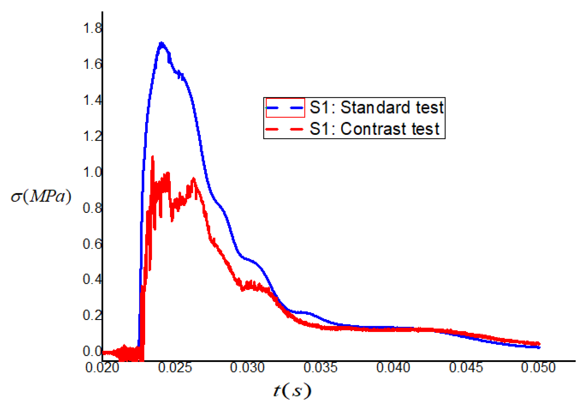
Figure 12.
Stress time–history curve of measuring point S6.

Figure 13.
Stress time–history curve of measuring point S7.
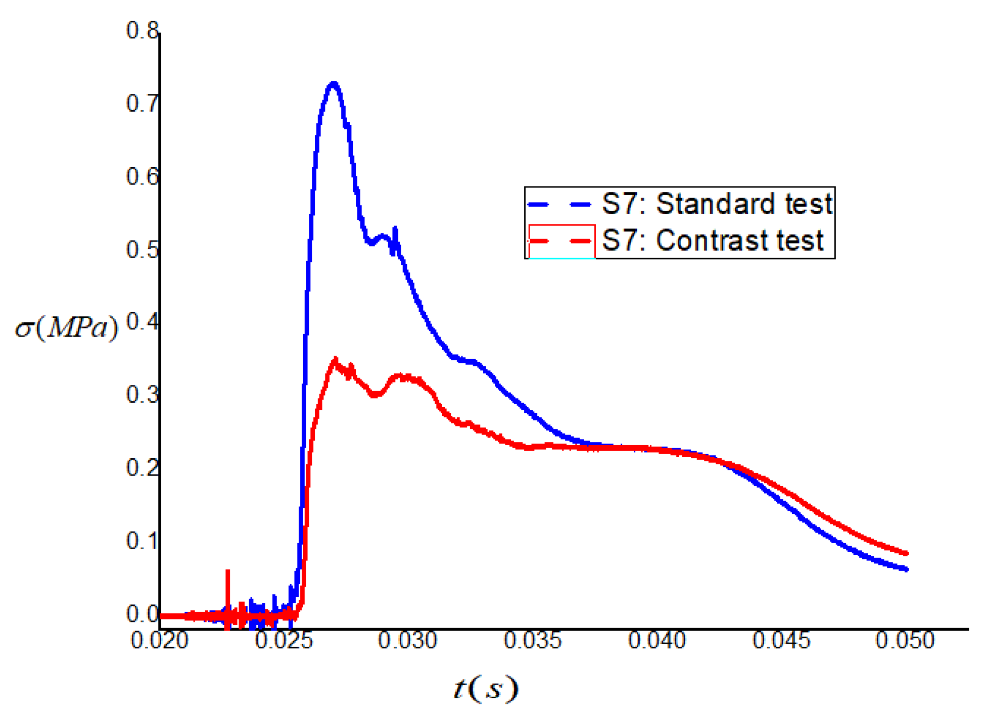
Figure 14.
Stress time–history curve of measuring point S8.

Figure 15.
Strain energy of the sand and ceramic foam.


Table 1.
Material parameters of TNT (dimension: SI system).
| 1630 | |
| 6930 | |
| 2.06 × 10¹⁰ | |
| 6.0 × 10⁹ | |
| 4573 |
Table 2.
JWL equation of state of TNT (dimension: SI system).
| 373 × 109 | |
| 3.23 × 10⁹ | |
| 4.15 | |
| 0.95 | |
| 0.30 |
Table 3.
Material parameters of sand (LS-DYNA) (dimension: SI system).
| (Density) | 1800 |
| (Bulk modulus) | 3.0 × 10⁹ |
| (Shear modulus) | 0.6 × 10⁹ |
| (Material constant) | 6.47 × 10⁶ |
| (Material constant) | 6.40 × 10⁶ |
| (Material constant) | 4.14 × 10⁻⁹ |
| (Material constant) | 800 |
| (Material constant) | 0.26 |
Table 4.
Material parameters of reinforced concrete slab (dimension: SI).
| (Density) | 2500 |
| (Bulk modulus) | 8.5 × 10¹⁰ |
| (Shear modulus) | 1.486 × 10¹⁰ |
| (Young’s modulus) | 3.57 × 10¹⁰ |
| (Material constant) | 0.79 |
| (Material constant) | 1.60 |
| (Material constant) | 0.0007 |
| (Material constant) | 0.04 |
| (Material constant) | 1.0 |
| (Material constant) | 8.5 × 10¹⁰ |
| (Material constant) | −1.71 × 10¹¹ |
| (Material constant) | 0.61 |
| (Crushed hydrostatic pressure) | 1.6 × 10⁷ |
| (Ultimate hydrostatic pressure) | 8.0 × 10⁸ |
| (Maximum tensile hydrostatic pressure) | 4.0 × 10⁶ |
| (Crushing volume strain) | 0.001 |
| (Volume strain) | 0.1 |
| (Uniaxial compressive strength) | 4.8 × 10⁷ |
| (Damage constant) | 0.001 |
| (Dimensionless strength) | 7.0 |
Table 5.
Direction peak stress of the experiments (unit: MPa).
| Measuring Points | S1 | S6 | S7 | S8 |
|---|---|---|---|---|
| Standard Test 1 | 1.75 | 0.98 | 0.75 | 0.37 |
| Contrast Test 2 | 1.03 | 0.55 | 0.35 | 0.26 |
Disclaimer/Publisher’s Note: The statements, opinions and data contained in all publications are solely those of the individual author(s) and contributor(s) and not of MDPI and/or the editor(s). MDPI and/or the editor(s) disclaim responsibility for any injury to people or property resulting from any ideas, methods, instructions or products referred to in the content. |
© 2023 by the authors. Licensee MDPI, Basel, Switzerland. This article is an open access article distributed under the terms and conditions of the Creative Commons Attribution (CC BY) license (https://creativecommons.org/licenses/by/4.0/).
Share and Cite
MDPI and ACS Style
Hao, Y.-Q.; Ye, Z.-B.; Zhou, X.-G. Field Test and Numerical Simulation of a New Layered Structure. Buildings 2023, 13, 1742. https://doi.org/10.3390/buildings13071742
AMA Style
Hao Y-Q, Ye Z-B, Zhou X-G. Field Test and Numerical Simulation of a New Layered Structure. Buildings. 2023; 13(7):1742. https://doi.org/10.3390/buildings13071742
Chicago/Turabian StyleHao, Ying-Qi, Zhong-Bao Ye, and Xin-Gui Zhou. 2023. "Field Test and Numerical Simulation of a New Layered Structure" Buildings 13, no. 7: 1742. https://doi.org/10.3390/buildings13071742
Note that from the first issue of 2016, this journal uses article numbers instead of page numbers. See further details here.