
Mechanical Properties of Fire-Damaged RC Beams Reinforced with Carbon Fiber Mesh

1
Suqian City Construction Investment (Group) Co., Ltd., Suqian 223800, China
2
School of Mechanics and Civil Engineering, China University of Mining and Technology, Xuzhou 221116, China
3
School of Materials Science and Engineering, Southeast University, Nanjing 211189, China
*
Author to whom correspondence should be addressed.
Buildings 2024, 14(4), 1166; https://doi.org/10.3390/buildings14041166
Submission received: 31 March 2024
/
Revised: 13 April 2024
/
Accepted: 18 April 2024
/
Published: 20 April 2024
(This article belongs to the Section Building Materials, and Repair & Renovation)
Abstract
:The bearing capacity of reinforced concrete (RC) beam will be weakened by fire. It is necessary to strengthen RC beams after fire. The carbon fiber mesh (CFM) can be used to reinforce RC beams. In this paper, RC beams were exposed to varying temperatures, followed by reinforcement with varying layers of CFM. The influence of the heating temperature and the number of CFM layers on the flexural performance of RC beams was investigated. The results indicated that the cracking loads of RC beams were 18.2, 16.4, 16.3, and 15.5 kN when the RC beams were subjected to room temperatures, 150, 350, and 550 °C. Compared to the unreinforced beams at room temperature, the cracking loads of the RC beams were reduced by 9.89%, 10.44%, and 14.84%. As the quantity of CFM reinforcement layers rises, so does the ultimate bearing capacity. For example, when the temperature was 150 °C, the ultimate loads of the beams with one and three layers of CFM were increased by 20% and 31.76% compared to the reference beam. When the temperature was 350 °C, the ultimate loads of the beams with one and three layers of CFM were increased by 19.51% and 28.04% compared to the RC beam without CFM. When the temperature was 550 °C, the ultimate loads of the beams with one and three layers of CFM were increased by 20% and 26.67% compared to the RC beam without CFM. Fire-damaged RC beams can be strengthened by one layer of CFM and mortar if the temperature was below 350 °C. Fire-damaged RC beams can be strengthened by three layers of CFM and mortar if the temperature was below 550 °C. The mechanical properties can be obviously enhanced.
1. Introduction
Every year, there are numerous buildings under construction and reinforcement. At the same time, the number of fire incidents related to the development of the construction industry is also on the rise. Building fires are a frequent occurrence and result in serious losses [1]. Elevated temperatures can cause a reduction in the bearing capacity of RC beams, which, in turn, can compromise the safety and reliability of the structure. Once RC beams lose their bearing capacity under fire, they will not be able to support the entire weight of the upper structure components, leading to damage to the building [2].
The structural performance of RC beams under fire is influenced by the compressive strength and protective layer thickness of RC beams [3]. The time–temperature profiles were found to be independent of concrete strength. The time–temperature profiles and the deflection increase rates of both common-strength and high-strength concrete beams were similar. However, the deflection increase rates of high-strength concrete beams became very high after spalling. Furthermore, the temperature, stiffness, and ductility of fire-damaged beams were significantly affected by the loads, cross-sectional size, and fire exposure time [4]. Ultra-high-performance fiber-reinforced concrete beams were more prone to spalling on both sides of the compression zone of the beam’s cross-section as compared to normal or high-strength concrete beams. This resulted in a lower fire resistance in UHPFRC beams [5]. The duration of fire was considered the most important parameter determining the failure probability of concrete beams. Material changes and load changes could be ignored in fire design [6]. Compared with HSC and NSC beams, the UHPC beams exhibited severe fire spalling and exhibited lower fire resistance [7].
The flexural behavior of RC beams strengthened with textile-reinforced concrete (TRC) has been studied. The crack and permeability resistance is strengthened by TRC. U-shaped TRC should be used, as the reinforcement may fall off when only the bottom is reinforced [8]. As the number of TRC layers increases, the ultimate load of RC beams gradually rises [9]. The fatigue life of TRC-reinforced beams was significantly superior to that of RC beams without reinforcement. Under the same texture ratio, the fatigue life of single-sided TRC-reinforced beams was longer than that of U-shape TRC-reinforced beams [10]. In addition, the flexural and crack behaviors of concrete beams reinforced with bottom ash and fly ash was examined [11]. It was pointed out that when the bottom ash ratio in the concrete mixture is enhanced, maximum deflection in the concrete beam diminishes. The widths of these cracks increase with fly ash ratios below 50%. Mechanical behavior in terms of the shear and bending performance of reinforced concrete beam using waste fire clay as a replacement for the aggregate has been proven to be effectively enhanced [12]. The waste fire clay content of bending-reinforced concrete beams increases their ability at the maximum level in the range of 20–30%; therefore, it can be said that the optimum waste fire clay content for shear-reinforced concrete beams is 20%. Başaran et al. strengthened the shear-deficient-reinforced concrete beams, considering different waste marble dust and stirrup spacings. The amount of waste marble dust is inversely proportional to the bending stiffness of reinforced concrete beams [13]. Özkılıç et al. investigated the shear performance of reinforced expansive concrete beams utilizing aluminum waste [14]. It was observed that the load capacity of the Al refuse combined with reinforced concrete beams increases with the stirrup reinforcement reductions compared with the reference reinforced concrete beams. The aluminum waste in reinforced concrete shear beams comprises up to 1% of the total beam.
The anchoring system effectively restricted the deflection of reinforced beams after the debonding of carbon-fiber-reinforced polymer CFRP fabrics [15]. In addition, the fire-induced axial restraining force significantly improved the fire resistance of CFRP-reinforced and unreinforced RC beams when the location of the restraining force was below the beam. The fire-resistant design of CFRP-reinforced components could obtain three possible fire resistance thickness calculation models based on the reduction in load levels [16]. Kodur et al. proposed a method for assessing the fire endurance of RC beams reinforced with various types of fiber-reinforced polymers (FRP) [17]. This method was based on the traditional fire protection design guidelines of RC beams, while also incorporating the contributions of FRP and fire insulation materials in the fire protection calculation. Prior to elevated temperature tests, the RC beams were reinforced using textile-reinforced concrete (TRC) [18]. Finite element analysis (FEA) software of MSC Software and MARC MENTAT software was utilized to analyze the temperature field distribution of the cross-section of the RC beam under elevated-temperature conditions. The reinforced beam could effectively improve the bending stiffness of the component. Additionally, composite materials such as basalt-fiber-reinforced polymers and hybrid-fiber-reinforced polymers were also used to strengthen the RC beam. The increased load-carrying capacity in HFRP-RC beams is due to the thermal expansion coefficient of carbon fibers used in HFRP, resulting in a smaller deflection of pre-stressed beams [19]. The beams with intact reinforcement and thermal damage repair showed a better load-bearing capacity and toughness [20]. Compared to the control beams, the flexibility and toughness of RC beams were reduced. Different performance indicators indicated that carbon fiber cloth has good potential for repairing thermally damaged beams. The load-carrying capacity was improved by up to 34% after the fire beams were strengthened. Reinforcing fire-damaged beams with EB-CFRP can significantly reduce the effects of fire and restore their initial stiffness [21].
Many researchers have conducted extensive research on the reinforcement of RC beams with FRP. But most of the research results were mainly obtained from RC beams which were strengthened first, then the FRP and the RC beams were both exposed to elevated temperature [16,17,19]. However, the beams which were strengthened with FRP first were destroyed due to reinforcement failure after being exposed to elevated temperatures. Only a few investigations were performed on the mechanical properties of fire-damaged RC beams which were reinforced with CFRP [21,22]. CFRP can effectively increase the first cracking load and decrease the deflection of RC beams. There are few studies on the flexural performance of fire-damaged RC beams reinforced with CFM. Hence, it was essential to study the properties of RC beams reinforced with CFM.
This study aims to assess the effect of elevated temperatures and CFM layers on the bearing capacity of RC beams. RC beams, after being heated at elevated temperatures, were reinforced with CFM. Carbon fiber mesh and mortar were used to strengthen RC beams heated at different temperatures. The mechanical properties of RC beams reinforced with one and three layers of CFM were measured and analyzed. Then, the beams were tested by bending to obtain their ultimate bearing capacity, displacement, and crack development. The evolving pattern of flexural behavior exhibited by RC beams reinforced with CFM after being exposed to elevated temperature was studied.
2. Test Overview
2.1. Raw Material
The concrete utilized in this experiment was provided by a commercial concrete company, Jiangsu Chengyi Group Co., Ltd. (Xuzhou, China). The mix proportions of concrete were provided by the manufacturer, as shown in Table 1. Before being heated to a high temperature, the compressive strength of the concrete was 33.5 MPa. The compressive strength of the concrete decreased after exposure to temperatures of 150, 350, and 550 °C, which can be seen in Figure 1. According to the standards of concrete structures [23,24], the steel bars used in this study were HRB400 grade steel bars with diameters of 8 mm and 12 mm, which were produced by Jiangsu Xugang Iron and Steel Group Co., Ltd. (Xuzhou, China). The mechanical properties of the steel bars after heat damage at different temperatures are shown in Table 2.
The CFM used in the experiment was provided by Kaben Technology Group Co., Ltd. (Tianjin, China), with a mesh size of 20 × 20 mm. The tensile strength is above 4900 MPa. The CFM is shown in Figure 2. Its mechanical performance parameters are shown in Table 3. UGM-J polymer cement waterproof mortar produced by Nanjing Teheng Building Materials Technology Co., Ltd. (Nanjing, China). was used to prepare the reinforcing cement mortar. This type of polymer cement mortar, with a water content of 14% to 18%, was specialized for reinforcement of the quality of the grouting material. The polymer mortar exhibited a compressive strength of 41.8 MPa.
2.2. Sample Design and Production
The tested beam had a cross-sectional dimension of 150 × 260 mm and a total length of 2000 mm. Two steel bars with a diameter of 12 mm were employed to reinforce the lower part of the beam, while two steel bars with a diameter of 8mm were used for the load-bearing reinforcement of the upper part of the beam. The hoops inside the beam had a diameter of 8 mm and a spacing of 100 mm. The dimensions and reinforcement design of the beams are outlined in Figure 3. The grouping of beams is shown in Table 4.
To monitor the temperature field within the beam during the heating process, K-type thermocouples were settled at different locations on the beam’s cross-section, as shown in Figure 4.
2.3. Heating Test
The heating test was conducted after being cured for 28 days. A heating furnace with a power of 24 kW and a maximum temperature of 1100 °C was used. The beam was heated at a rate of 10 °C/min. After reaching the target temperature, it was kept at a constant temperature for 90 min, and then the beam was cooled down in the air. The heating schematic and the elevated-temperature heating device are shown in Figure 5.
2.4. Beam Reinforcement
After being cooled, the beam was roughened and then reinforced with CFM according to the standards of 13G311-1 [25], GB 50367-2013 [26], and CECS146:2003 [27]. The bottom and two sides of the beam should be reinforced with CFM; the reinforcing area is shown in Figure 6a. After completing the reinforcement construction of the CFM at the bottom and two sides of the RC beam, the beam should be further reinforced by adding a U-shape CFM. A U-shape CFM is installed at each end of the RC beam and at the load application point to enhance the shear resistance. The detail reinforcement diagram for reinforcing the RC beam with CFM is shown in Figure 6.
2.4.1. Construction Process for Reinforcing RC Beams with One-Layer CFM
(1) Surface preparing of the beam
The beams should be treated by chiseling the surface to remove the soft part of the surface. A total of 3–5 mm of the top layer of concrete needs to be chiseled off to enhance the bond strength between the cement mortar and the new surface layer of the RC beam. A blower is used to fully remove the dust, the debris, and the loose concrete to ensure the bond strength between the reinforcing cement mortar and the surface layer of the RC beams.
(2) Polymer cement mortar mixing
The polymer mortar was mixed according to the specified water/cement ratio suggested by the manufacturer. The mortar was well mixed for 10–15 min.
(3) Daubing the first layer of polymer cement mortar
The polymer cement mortar was initially applied onto the chiseled surface of the structure. The thickness of the first layer of mortar was 3 mm. The thickness of the applied polymer cement mortar was controlled by using wooden strips.
(4) Laying the first layer of CFM
The CFM was cut according to the design requirements, as shown in Figure 6. The fiber mesh was paved on top of the polymer cement mortar; the direction of the CFM should be set according to the design direction. The fiber mesh was temporarily fixed on the end to ensure the overall CFM surface flatness. The fiber mesh should be pressed into the polymer cement mortar and the surface should be smoothed with a trowel.
(5) Daubing the second layer of cement mortar
After the first layer of polymer cement mortar was laid, the second layer of polymer cement mortar could be applied. The thickness of the applied mortar was 3 mm to avoid over-thickening of the mortar. After the application was completed, the surface was smoothed with a trowel.
(6) U-shaped hoop CFM
After the reinforcement of the bottom and sides of the specimen, the specimen was reinforced with the U-shape hoop CFM at the designated positions. First of all, the mold of the U-shape hoop was built at the set position on the beam, and the cut CFM was laid onto the polymer mortar. After the initial setting of the underlying polymer cement mortar, the next layer of polymer cement mortar could be applied.
(7) Surface flattening
The surface of the reinforcement layer of the beam was leveled and compacted using a trowel. After the mortar was daubed, it was maintained at a certain level of humidity. After being cured for 28 days, the beams could be tested for bending.
2.4.2. Construction Process of Three-Layer CFM
The construction process for reinforcing the three-layer CFM is the same as that for the layer of CFM reinforcement mentioned above. The bottom of the beam is reinforced with three layers of CFM in the order of cement mortar, CFM, cement mortar, CFM, and cement mortar. Only one layer of CFM is added to the beam’s side. After the reinforcement of the bottom and two sides of the beam is completed, the U-shaped hoop reinforcement is carried out according to the above operation process to complete the three-layer CFM reinforcement. The specific reinforcement construction plan can be found in Figure 6d,e.
2.5. Loading Devices and Systems
The four-point bending loading method was utilized to conduct tests on the RC beams. The beam was placed on a fixed support and rolling support, and a hydraulic jack was suspended and fixed on a reaction frame. The load applied by the jack acted on the load distribution beam and was transmitted to the beam. The beam’s net span was 1800 mm. The distance between the two loading points was 600 mm. The jack was utilized to apply the vertical load throughout the experimental procedure. Figure 7 illustrates the schematic diagram of the loading device and the loading device diagram.
During the initial loading stage, the load applied at each stage was 10% of the calculated ultimate load. When approaching the cracking point, the load applied at each level was reduced to 5% of the estimated ultimate load. Each load level was maintained for 10 min and data were collected.
The development of cracks was observed, and the corresponding load values were recorded. To assess the displacement of the beam, three displacement gauges were placed at the bottom of the beam, one at the mid-span, and two at the loading points. To determine the maximum displacement at mid-span and the displacement variations at the loading points, YHD-100 displacement meters were utilized. Additionally, one displacement meter was set up at each of the two supports on the upper surface of the beam. The displacement meters were connected to the UT7160 high-speed static strain gauges to obtain displacement data. The layout of the displacement meter is shown in Figure 7a.
Before the bending test, the beams were painted white. Following the test, the cracks on the beam surface were drawn and labeled using a marker pen. At the end of each loading level, the width of the cracks was measured using a crack observer. Any cracks visible on the surface of the beams were recorded and observed.
3. Experimental Results and Analysis
3.1. Internal Temperature of the Specimen
As the temperatures increased to 150, 350, and 550 °C, the internal temperature of the specimen showed an upward trend. When the surface temperature of the furnace reached 150, 350, and 550 °C, and remained there for 90 min, the temperatures at the center point inside the beam were 92, 148, 302, and 410 °C, respectively. Overall, the temperature change inside the beam was mainly influenced by the distance from the heating surfaces of the beam.
3.2. Phenomenon during the Loading Process
The damage diagrams of the RC beams are depicted in Figure 8. During the loading process, cracks were first observed at the underside of the RC beam. The load at the occurrence of the first crack is called the cracking load. As the load continued to increase, more and more cracks emerged on the surface of the beam. The cracks on the beam surface gradually moved upwards. Upon reaching a certain load, transverse cracks emerged in the concrete at the top of the beam. At a certain load, the RC beam reached its peak load-carrying capacity. The load at the peak load-carrying capacity is called the ultimate load. As the displacement continued to increase, the concrete in the compression zone at the top of the beam was crushed, and the beam was destroyed. For the RC beams at room temperature, the cracking load of T20-0, T20-1, and T20-3 is 18.2, 24.0, and 26 kN, respectively. The ultimate load is 87.0, 108.0, and 115.0 kN respectively. For the RC beams at a temperature of 150 °C, the cracking load of T150-0, T150-1, and T150-3 is 16.4, 22.0, and 25 kN, respectively. The ultimate load is 85, 102, and 112 kN, respectively. For the RC beams at a temperature of 350 °C, the cracking load of T350-0, T350-1, and T350-3 is 16.3, 21.4, and 24 kN, respectively. The ultimate load is 82.0, 98.0, and 105 kN, respectively. For the RC beams at a temperature of 550 °C, the cracking load of T550-0, T550-1, and T550-3 is 15.5, 16.8, and 18.6 kN, respectively. The ultimate load is 75.0, 90.0, and 95.0 kN, respectively.
3.3. Failure Modes Analysis of RC Beams
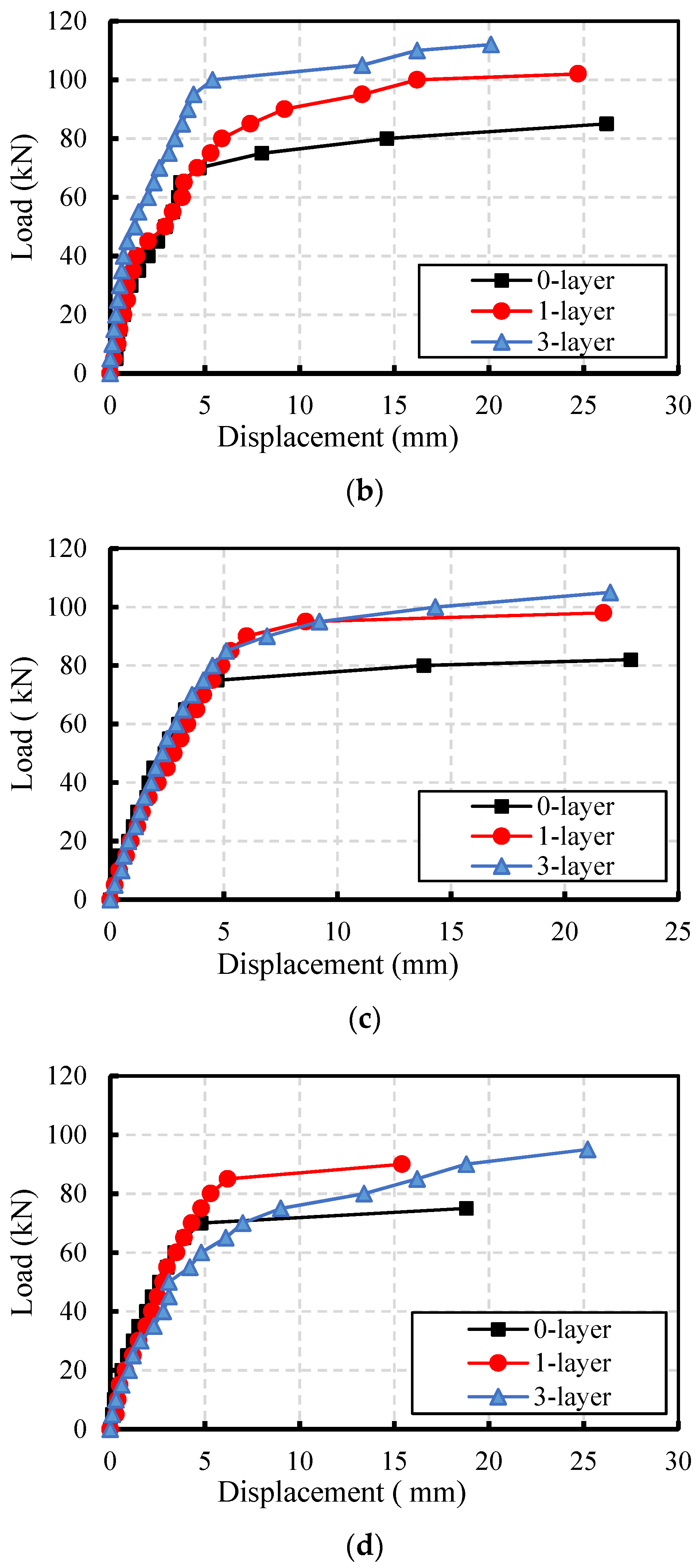
Through a comparison of crack development in the unreinforced beams at various temperatures, it is evident that the number of cracks in beams at room temperature was small. However, after being heated to an elevated temperature, vertical cracks started to develop from the bottom and extended upward. The main reason for this is that elevated temperatures caused initial crack damage in the concrete. The increase in vertical cracks at the bottom of the RC beams heated to a high temperature was also related to the initial cracks.
Compared with the cracks in the unreinforced beams, it can be seen that with an escalating number of CFM layers, the number of cracks multiplied significantly and the crack lengths were much longer. By comparing the final damage patterns, it can be seen that the concrete damage in the unreinforced beams was more serious, while the concrete of the reinforced specimen did not show obvious compression damage. The vertical cracks of reinforced beams extended longer than those of the unreinforced beams. This is mainly because the CFM at the bottom of the reinforced beam bears the main tensile force. It can be clearly seen that the concrete was crushed between the loading points, which was similar to what was observed in the literature [13]. As the amount of tensile reinforcement outside of the beam increased, the beam-bending ability increased. This is due to the increase in the tensile strength due to the CFM at the bottom of the RC beams. Similar results were observed, showing that as the tensile reinforcement ratio increases, the beam bending ability increases [12]. The CFM effectively restricted and retarded the development of displacement. The CFM enhanced the beam-bearing capacity of beams, leading to a more adequate development of vertical cracks. Similar results were observed, showing that the bending deformation was significantly increased, although the load was reduced after the ultimate value [14]. Flexural damage occurred in all of the beams.
In addition, the maximum crack width of CFM-reinforced beams was significantly reduced. For the unheated beams, the maximum crack widths of unreinforced beams and beams reinforced with one-layer and three-layer CFM were 2.46, 1.73, and 1.68 mm, respectively. For the beams heated to 150 °C, the maximum crack widths of unreinforced beams and beams reinforced with one-layer and three-layer CFM were 2.24, 1.68, and 1.53 mm, respectively. For the beams heated to 350 °C, the maximum crack widths of unreinforced beams and beams reinforced with one-layer and three-layer CFM were 2.45, 3.04, and 1.33 mm, respectively. For the beams heated to 550 °C, the maximum crack widths of unreinforced beams and beams reinforced with one-layer and three-layer CFM were 2.68, 2.04, and 0.96 mm, respectively. The cracks that occurred in concrete beams under loads were significant flexural cracks, as shown in Figure 8. No obvious shear cracks were observed, as presented in References [11,12].
3.4. The Impact of Temperature on the Load–Displacement Curve of Beams
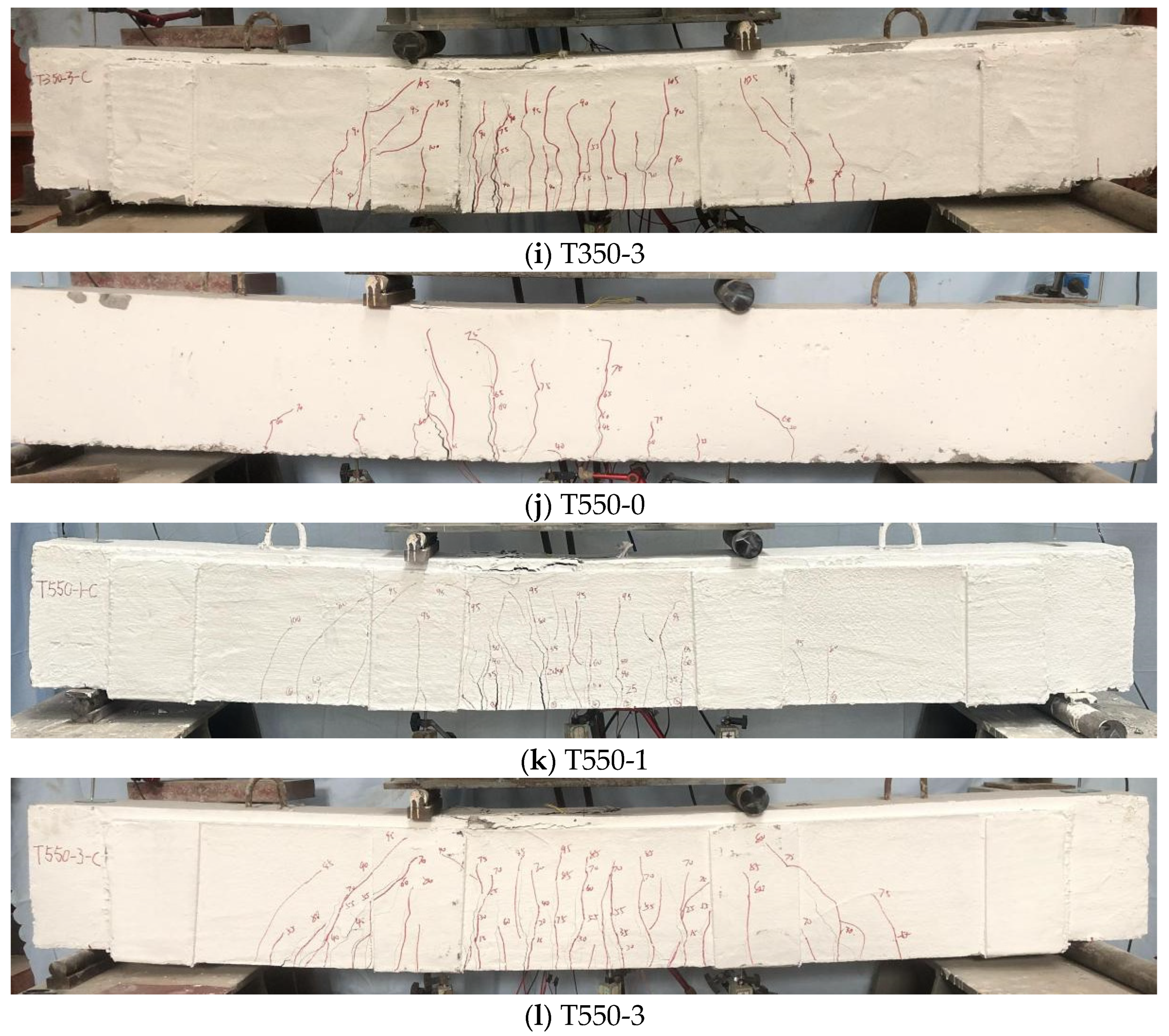
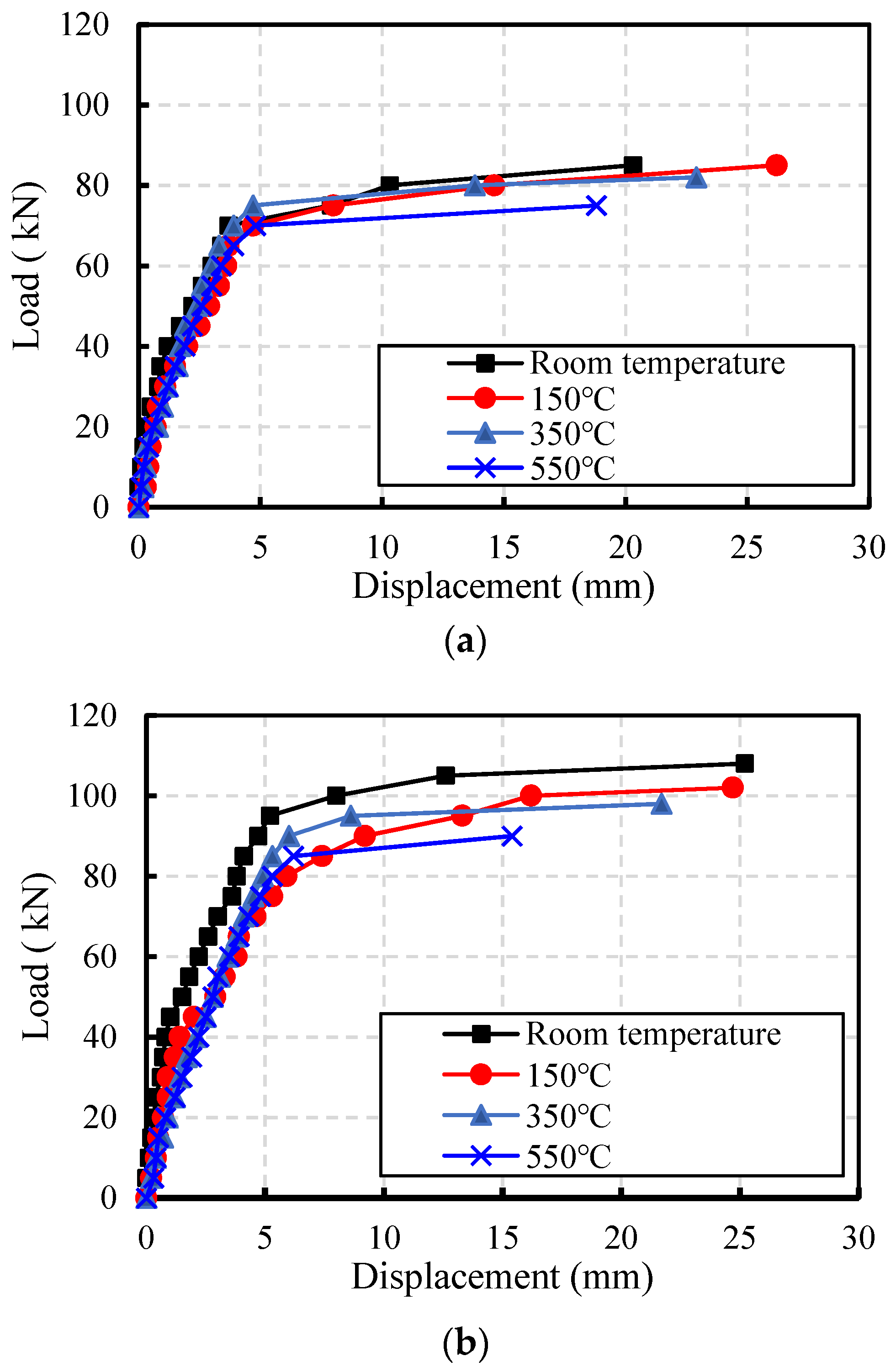
Figure 9 illustrates the load–displacement curves of each RC beam under different temperatures with the same number of CFMs.
Figure 9a shows the load–displacement curves of unreinforced RC beams at various temperatures. In the initial phase of the curve, the vertical displacement demonstrated a linear increase in relation to the load. As the displacement at the mid-span of the beam reached approximately 5 mm, a plateau period occurred with the increase in load. This is mainly due to the yield stage of the steel bars at the bottom of the beam. With the continuous increase in load, the vertical displacement slightly increased until the beam failed. The influence of temperature on the trend of the load–displacement curve of unreinforced RC beams was insignificant. This is because the bearing capacity of the beam was controlled by the steel bars at the bottom of the beam. The elevated temperature did not significantly affect the ultimate bearing capacity of the steel bars. It was observed that the initial flexural stiffness of the RC beam reduced after it was exposed to elevated temperatures. The reason for this was that the initial cracks caused by heat damaged the stiffness of the RC beams. As the temperature increased, the beam’s ultimate load gradually decreased. When the RC beam was subjected to temperatures of 150, 350, and 550 °C, the bearing capacity near failure was 85, 82, and 75 kN, respectively. The bearing capacity of RC beams damaged at temperatures of 150, 350, and 550 °C was 97.7, 94.3, and 86.2% of the beams at room temperature, respectively. When the RC beam was subjected to temperatures of below 350 °C, the RC beam’s ultimate bearing capacity was influenced negligibly by the temperature. However, when the RC beams were heated to 550 °C, the ultimate bearing capacity of the RC beams underwent a considerable decline.
When the RC beam was subjected to temperatures of 150, 350, and 550 °C, the ultimate displacement of the RC beam near failure was 26.2, 22.9, and 18.8 mm, respectively. The ultimate displacement of the RC beam after being heated to temperatures of 150, 350, and 550 °C was 90.7%, 79.2%, and 65.1% of the beam at room temperature, respectively. However, when the heating temperature was 550 °C, the ultimate displacement of the beam significantly decreased.
Figure 9b shows the load–displacement curve of RC beams reinforced with one layer of CFM. The load–displacement curve of the beams reinforced with one layer of CFM shows a similar trend to that of the unreinforced beams. The initial flexural stiffness of the beams at room temperature exceeded that of the heated beams. As the temperature rose, the RC beam’s ultimate load gradually decreased. Upon exposure to temperatures of 150, 350, and 550 °C, the bearing capacity of the RC beam was 102, 98, and 90 kN, respectively. The bearing capacity of RC beams subjected to 150, 350, and 550 °C was 94.4%, 90.7%, and 83.3% of the control beam at room temperature, respectively. When the temperature was no higher than 350 °C, the temperature had a minimal impact on the RC beam’s ultimate bearing capacity. However, when the temperature was 550 °C, the RC beam’s ultimate bearing capacity underwent a considerable decline.
When the RC beam was subjected to temperatures of 150, 350, and 550 °C, the displacement of the RC beam was 24.7, 21.7, and 15.4 mm, respectively. The displacement of the RC beam heated to temperatures of 150, 350, and 550 °C was 98%, 86.1%, and 61.1% of the beam at room temperature, respectively.
Figure 9c shows the load–displacement curve of RC beams reinforced with three-layer CFM after being heated to different temperatures. As the heating temperature increased, the plateau period and inflection point were no longer obvious. In addition, as the temperature increased, the RC beam’s ultimate load would gradually decline. After being heated to 150, 350, and 550 °C, the bearing capacity of the RC beams was 112, 105, and 95 kN, respectively. The bearing capacity of RC beams subjected to temperatures of 150, 350, and 550 °C was 97.4%, 91.3%, and 82.6% of that of the control beam, respectively. When the temperature was lower than 350 °C, the ultimate bearing capacity of the RC beam decreased slowly. However, at 550 °C, the ultimate bearing capacity of the RC beam significantly decreased.
When the RC beam was subjected to temperatures of 150, 350, and 550 °C, the mid-span displacement of the near-failure of the RC beam was 20.1, 22, and 25.2 mm, respectively. Therefore, the displacement of the RC beam at temperatures of 150, 350, and 550 °C was 0.99, 1.084, 1.241 times that of the beam at room temperature.
The bending properties of fire-damaged RC beams were obviously enhanced with CFM. Basalt-fiber-reinforced concrete beams showed excellent fire resistance, and were capable of resisting exposure to elevated temperatures for two hours, but showed a 70% reduction in strength capacity when compared to non-heated reference beams [19]. It was concluded that using CFRP sheets to reinforce fire-damaged beams considerably reduces the impacts of fire exposure. It was also enough to restore the majority of the stiffness that was lost [22].
3.5. Influence of CFM Layers on the Load–Displacement Curve of RC Beams
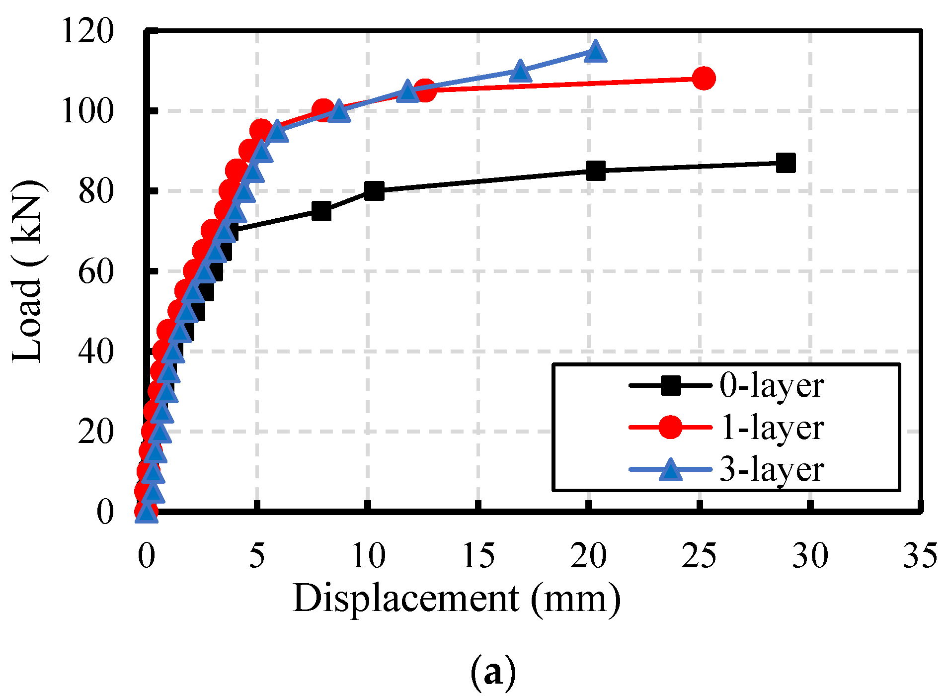
In Figure 10, the load–displacement curve of each RC beam reinforced with different layers of CFM is presented.
Figure 10a illustrates the load–displacement curves of RC beams with varying layers at room temperature. The results indicate that CFM effectively enhances the beam’s ultimate bending bearing capacity at room temperature. The number of CFM layers did not significantly influence the beam’s flexural stiffness at room temperature. The ultimate bearing capacity and ultimate displacement of the CFM-reinforced beams were obviously higher than those of the beams without CFM. The increase in the bearing ability of the beams during the elastic stage was the main reason for the delayed yield of the steel bars in concrete. The bearing capacity of RC beams at near failure increased from 87 kN for unreinforced beams to 108 and 115 kN for beams reinforced with one and three layers of CFM, respectively. The bearing capacity of RC beams with one and three layers of CFM was 1.24 and 1.32 times greater than that of the unreinforced RC beams, respectively.
When the number of CFM layers in reinforced RC beams was zero, one, and three, the displacement of the RC beams was 28.9, 25.2, and 20.3 mm, respectively. The displacement of RC beams with one and three layers of CFM was 0.872 and 0.702 times that of the control beam, respectively. The displacement of RC beams was significantly decreased by reinforcement with CFM.
Figure 10b depicts the load–displacement curves of RC beams heated to 150 °C. These curves were significantly influenced by the number of CFM layers. When the beams were reinforced with zero, one, and three layers of CFM, the RC beams’ bearing capacity was 85, 102, and 112 kN, respectively. The bearing capacity of RC beams with one and three layers of CFM was 1.2 and 1.318 times that of the unreinforced RC beams, respectively. After being heated to 150 °C, the RC beams’ ultimate bearing capacity will be obviously enhanced with the increase in the number of CFM layers.
When the RC beams were reinforced with zero, one, and three layers of CFM, the displacement of the RC beams was 26.2, 24.7, and 20.1 mm, respectively. The displacement of RC beams reinforced with one and three layers of CFM was 0.897 and 0.88 times of the control beam, respectively. For the RC beams heated to 150 °C, the displacement of the RC beams reinforced with one and three layers was 0.943 and 0.767 times that of the control group without CFM. When the RC beams were reinforced with CFM, the displacement of the RC beams slightly decreased.
The load–displacement curves of RC beams heated to 350 °C are presented in Figure 10c. The analysis reveals a notable enhancement in the bearing capacity of these beams, particularly when reinforced with multiple layers of CFM.
When RC beams were reinforced with zero, one, and three layers of CFM, the RC beams’ bearing capacity was 82, 98, and 105 kN, respectively. The bearing capacity of RC beams reinforced with one and three layers of CFM was 1.195 and 1.280 times that of the unreinforced RC beams, respectively. After being heated to 350 °C, the RC beams’ ultimate bearing capacity will be obviously augmented by the increasing CFM layers.
When the RC beams heated to 350 °C were reinforced with zero, one, and three layers of CFM, the displacement of the RC beams was 22.9, 21.7, and 22.0mm, respectively. The displacement of RC beams reinforced with one and three layers of CFM was 0.948 and 0.961 times that of the beam without CFM. With the reinforcement of CFM, there was no significant change in the displacement of RC beams.
Figure 10d depicts the load–displacement curves of RC beams heated to 550 °C. It is evident from the figure that significant damage was caused to the beams by the elevated temperature, while the bearing capacity and ductility of the beams were improved by reinforcement with CFM. When the RC beams were reinforced with zero, one, and three layers of CFM, the RC beams’ bearing capacity was 75, 90, and 95kN, respectively. The bearing capacity of RC beams reinforced with one and three layers of CFM was 1.2 and 1.267 times that of the unreinforced RC beams, respectively. After being heated to 550 °C, the RC beams’ ultimate bearing capacity will be obviously augmented by the increasing CFM layers.
When the RC beams heated to 550 °C were reinforced with zero, one, and three layers of CFM, the displacement of the RC beams was 18.8, 15.4, and 25.2 mm, respectively. The mid-span displacement of RC beams with one and three layers of CFM was 0.819 and 1.34 times that of the beam without CFM, respectively. Although the number of CFM layers used to reinforce RC beams increased from one to three, the displacement of the RC beams decreased. The RC beam reinforced with one layer of CFM exhibited better ductility than the beam reinforced with three layers of CFM. This is due to the increase in the tensile strength caused by the CFM at the bottom of the RC beams. Similar results were observed: as the tensile reinforcement ratio increased, the beam bending ability increased [12]. Additionally, similar results were observed, showing that the bending deformation significantly increased even though the load was reduced after reaching the ultimate value [14].
4. Analysis of the Mechanical Properties of RC Beams
Drawing upon the experimental data derived from displacement sensors and pressure sensors, combined with experimental observation, the cracking load, ultimate load, and ultimate displacement of the beams are detailed in Table 5.
It is evident that an elevated temperature would have a considerable effect on the RC beams’ cracking load. As the temperature rose, the cracking load of RC beams gradually decreased. The crack loads of the unreinforced RC beams at room temperature, 150, 350, and 550 °C were 18.2, 16.4, 16.3, and 15.5 kN, respectively. This is primarily due to the fact that the elevated temperatures cause initial stress cracks on the concrete surface. The impact of stress cracks due to temperature increases as the temperature rises, which can cause RC beams to crack under small loads.
Through comparison with the heated RC beams without CFM, a marked improvement in the bearing capacity of the beams reinforced with CFM became apparent.
After the beams were heated to 150 °C, the ultimate loads of the beams reinforced with zero, one, and three layers of CFM were 85, 102, and 112 kN, respectively. The bearing capacity of the RC beam with CFM increased by 20% and 31.76%, respectively.
5. Conclusions
The flexural performance and damage morphology of fire-damaged RC beams reinforced with CFM were investigated. Based on the evaluation of the impact of elevated temperatures and varying CFM layer counts, the following conclusions can be drawn regarding the mechanical properties of RC beams.
(1) As the temperature increased, the cracking load and ultimate load of the RC beam gradually decreased. The bearing capacity of RC beams at temperatures of 150, 350, and 550 °C was 97.7, 94.3, and 86.2% that of the beams at room temperature.
(2) With the increase in the number of reinforced layers, the maximum crack width was substantially reduced and the number of mid-span flexural cracks gradually increased. The displacement of RC beams with one and three layers of CFM was 0.872 and 0.702 times that of the beam at room temperature, respectively.
(3) The effect of temperature on the initial stiffness of beams was obvious. The ultimate displacement of the RC beam after being heated to temperatures of 150, 350, and 550 °C was 90.7%, 79.2%, and 65.1% that of the beam at room temperature, respectively.
(4) As the number of CFM layers increased, the ultimate load capacity of the RC beams gradually increased. The bearing capacity of RC beams reinforced with one and three layers of CFM was 1.2 and 1.267 times that of the unreinforced RC beams, respectively.
(5) The mechanical properties can be obviously enhanced by CFM. Fire-damaged RC beams can be strengthened by one layer of CFM and mortar if the temperature is below 350 °C. Fire-damaged RC beams can be strengthened by three layers of CFM and mortar if the temperature is below 550 °C.
Author Contributions
Conceptualization, G.Y.; data curation, H.W., Z.X. and G.Y.; formal analysis, H.W. and Z.X.; funding acquisition, Z.X. and Q.L.; investigation, H.W. and Z.X.; methodology, G.Y.; project administration, G.Y.; resources, J.C., G.Y. and Q.L.; supervision, G.Y.; validation, H.W., G.Y. and Q.L.; visualization, Z.X.; writing—original draft, J.C.; writing—review and editing, Z.X. and Q.L. All authors have read and agreed to the published version of the manuscript.
Funding
This research was funded by the National Natural Science Foundation of China, grant number 51208504 and 52208231.
Data Availability Statement
The original contributions presented in the study are included in the article, further inquiries can be directed to the corresponding author.
Conflicts of Interest
Author Jinsheng Cheng was employed by the company Suqian City Construction Investment (Group) Co., Ltd. The remaining authors declare that the research was conducted in the absence of any commercial or financial relationships that could be construed as a potential conflict of interest.
References
- Cui, Y.Q.; Peng, Y.L.; Luo, C.L. Study on the fire protection technologies for external thermal insulation system of the buildings. Appl. Mech. Mater. 2014, 638–640, 1646–1649. [Google Scholar] [CrossRef]
- Song, R.L. Research on Ultimate bearing capacity of reinforced concrete columns subjected to fire. Adv. Mater. Res. 2014, 1055, 171–174. [Google Scholar] [CrossRef]
- Choi, E.G.; Shin, Y.S. The structural behavior and simplified thermal analysis of normal-strength and high-strength concrete beams under fire. Eng. Struct. 2011, 33, 1123–1132. [Google Scholar] [CrossRef]
- Ryu, E.; Shin, Y.; Kim, H. Effect of loading and beam sizes on the structural behaviors of reinforced concrete beams under and after fire. Int. J. Concr. Struct. Mater. 2018, 12, 54. [Google Scholar] [CrossRef]
- Banerji, S.; Kodur, V.; Solhmirzaei, R. Experimental behavior of ultra high performance fiber reinforced concrete beams under fire conditions. Eng. Struct. 2020, 208, 110316. [Google Scholar] [CrossRef]
- Van Cao, V. Reliability-based moment capacity assessment of reinforced concrete beams in fire. Int. J. Civ. Eng. 2022, 20, 1291–1308. [Google Scholar] [CrossRef]
- Kodur, V.K.R.; Banerji, S. Comparative fire behavior of reinforced concrete beams made of different concrete strengths. Fire Technol. 2023. [Google Scholar] [CrossRef]
- Yin, S.; Yu, Y.; Xi, Y. Flexural performance of TRC-strengthened RC beam under chloride environment. Anti-Corros. Methods Mater. 2018, 65, 444–450. [Google Scholar] [CrossRef]
- Nahum, L.; Peled, A.; Gal, E. The flexural performance of structural concrete beams reinforced with carbon textile fabrics. Compos. Struct. 2020, 239, 111917. [Google Scholar] [CrossRef]
- Sheng, J.; Yu, Z.; Dou, G.; Liu, H. Fatigue damage behaviors of TRC-strengthened RC beams. Materials 2022, 15, 5113. [Google Scholar] [CrossRef]
- Karalar, M. Experimental and numerical investigation on flexural and crack failure of reinforced concrete beams with bottom ash and fly ash. Iran. J. Sci. Technol. Trans. Civ. Eng. 2020, 44, 331–354. [Google Scholar] [CrossRef]
- Özkılıç, Y.O.; Başaran, B.; Aksoylu, C.; Karalar, M.; Martins, C.H. Mechanical behavior in terms of shear and bending performance of reinforced concrete beam using waste fire clay as replacement of aggregate. Case Stud. Constr. Mater. 2023, 18, e02104. [Google Scholar] [CrossRef]
- Başaran, B.; Aksoylu, C.; Özkılıç, Y.O.; Karalar, M.; Hakamy, A. Shear behaviour of reinforced concrete beams utilizing waste marble powder. Structures 2023, 54, 1090–1100. [Google Scholar] [CrossRef]
- Özkılıç, Y.O.; Karalar, M.; Aksoylu, C.; Beskopylny, A.N.; Stel’makh, S.A.; Shcherban, E.M.; Qaidi, S.; Pereira, I.D.S.A.; Monteiro, S.N.; Azevedo, A.R.G. Shear performance of reinforced expansive concrete beams utilizing aluminium waste. J. Mater. Res. Technol. 2023, 24, 5433–5448. [Google Scholar] [CrossRef]
- Ahmed, A.; Kodur, V. The experimental behavior of FRP-strengthened RC beams subjected to design fire exposure. Eng. Struct. 2011, 33, 2201–2211. [Google Scholar] [CrossRef]
- Turkowski, P.; Łukomski, M.; Sulik, P.; Roszkowski, P. Fire resistance of CFRP-strengthened reinforced concrete beams under various load levels. Procedia Eng. 2017, 172, 1176–1183. [Google Scholar] [CrossRef]
- Kodur, V.K.R.; Yu, B. Rational Approach for evaluating fire resistance of FRP-strengthened concrete beams. J. Compos. Constr. 2016, 20, 04016041. [Google Scholar] [CrossRef]
- Douk, N.; Vu, X.H.; Larbi, A.S.; Audebert, M.; Chatelin, R. Numerical study of thermo mechanical behaviour of reinforced concrete beams with and without textile reinforced concrete (TRC) strengthening: Effects of TRC thickness and thermal loading rate. Eng. Struct. 2021, 231, 111737. [Google Scholar] [CrossRef]
- Protchenko, K. Residual fire resistance testing of basalt- and hybrid-FRP reinforced concrete beams. Materials 2022, 15, 1509. [Google Scholar] [CrossRef]
- Haddad, R.H.; Almomani, O.A. Recovering flexural performance of thermally damaged concrete beams using NSM CFRP strips. Constr. Build. Mater. 2017, 154, 632–643. [Google Scholar] [CrossRef]
- Abdulrahman, A.S.; Kadir, M.R.A. Behavior and flexural strength of fire-damaged high-strength reinforced rectangular concrete beams with tension or compression zones exposed to fire repaired with CFRP sheets. Case Stud. Constr. Mater. 2021, 15, e00779. [Google Scholar] [CrossRef]
- Abdulrahman, A.S.; Kadir, M.R.A. Behavior and flexural strength of fire damaged high strength reinforced rectangular concrete beams after strengthening with CFRP laminates. Ain Shams Eng. J. 2022, 13, 101767. [Google Scholar] [CrossRef]
- GB 50010-2015; Code for Design of Concrete Structures, Ministry of Housing and Urban Rural Development of the People’s Republic of China Code. General Administration of Quality Supervision, Inspection and Quarantine of the People’s Republic of China: Beijing, China, 2014. (In Chinese)
- GB 5508-2021; General Code for Concrete Structures, Ministry of Housing and Urban Rural Development of the People’s Republic of China Code. General Administration of Quality Supervision, Inspection and Quarantine of the People’s Republic of China: Beijing, China, 2014. (In Chinese)
- 13G311-1; Reinforced Concrete Structure. China Institute of Building Standard Design & Research: Beijing, China, 2013. (In Chinese)
- GB 50367-2013; Code for Design of Strengthening Concrete Structure, Ministry of Housing and Urban Rural Development of the People’s Republic of China Code. General Administration of Quality Supervision, Inspection and Quarantine of the People’s Republic of China: Beijing, China, 2014. (In Chinese)
- CECS 146:2003; Technical Specification for Strengthening Concrete Structures with Carbon Fiber Reinforced Polymer Laminate. China Association for Engineering Construction Standardization: Beijing, China, 2003. (In Chinese)
Figure 1.
Compressive strength of concrete after exposure to elevated temperature.
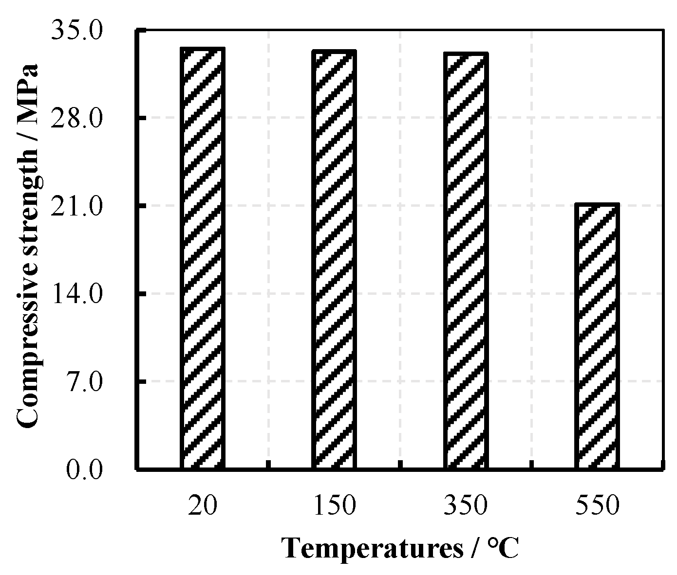
Figure 2.
Carbon fiber mesh (CFM).

Figure 3.
Beam dimensions and reinforcement (unit: mm).
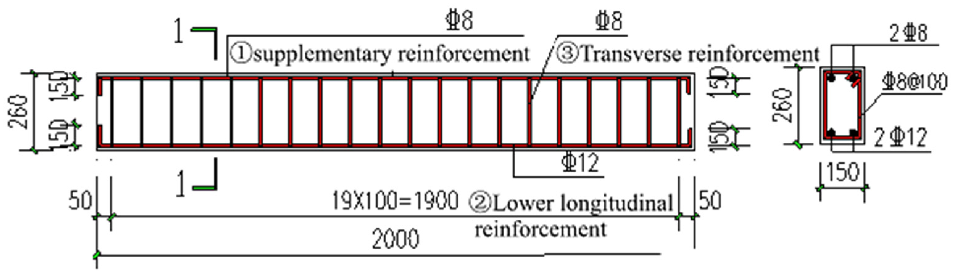
Figure 4.
Thermocouple arrangement in the beam (unit: mm).
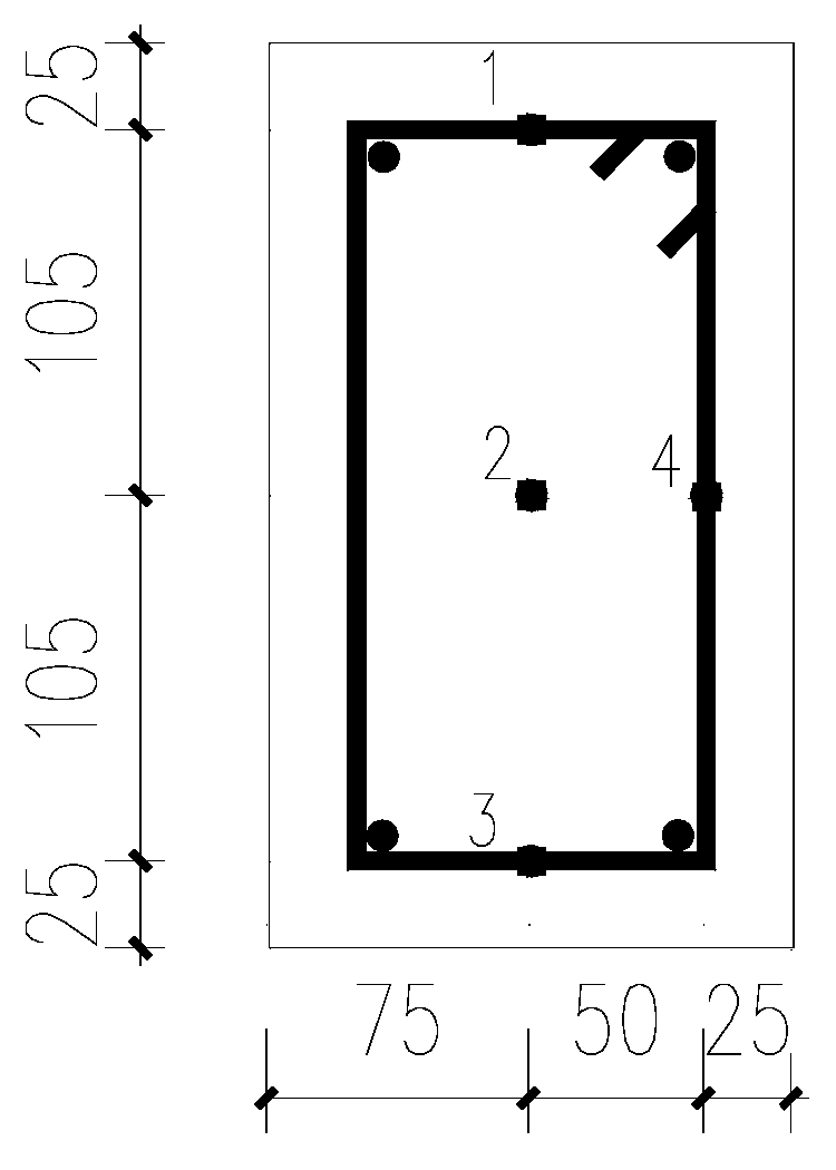
Figure 5.
Elevated-temperature test heating device and heating schematic diagram. (a) Schematic diagram of heating on three sides of the beam; (b) photo of heating on the third side of the beam.
Figure 5.
Elevated-temperature test heating device and heating schematic diagram. (a) Schematic diagram of heating on three sides of the beam; (b) photo of heating on the third side of the beam.

Figure 6.
Reinforcing diagram for RC beam. (a) Front elevation view of RC beam reinforcement; (b) one-layer section 1-1; (c) one-layer section 2-2; (d) three-layer section 1-1; (e) three-layer section 2-2.
Figure 6.
Reinforcing diagram for RC beam. (a) Front elevation view of RC beam reinforcement; (b) one-layer section 1-1; (c) one-layer section 2-2; (d) three-layer section 1-1; (e) three-layer section 2-2.
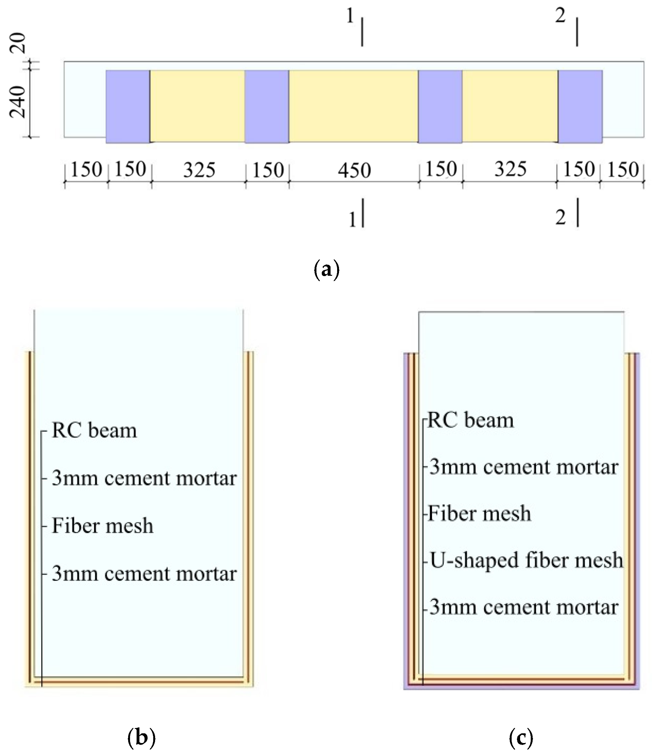
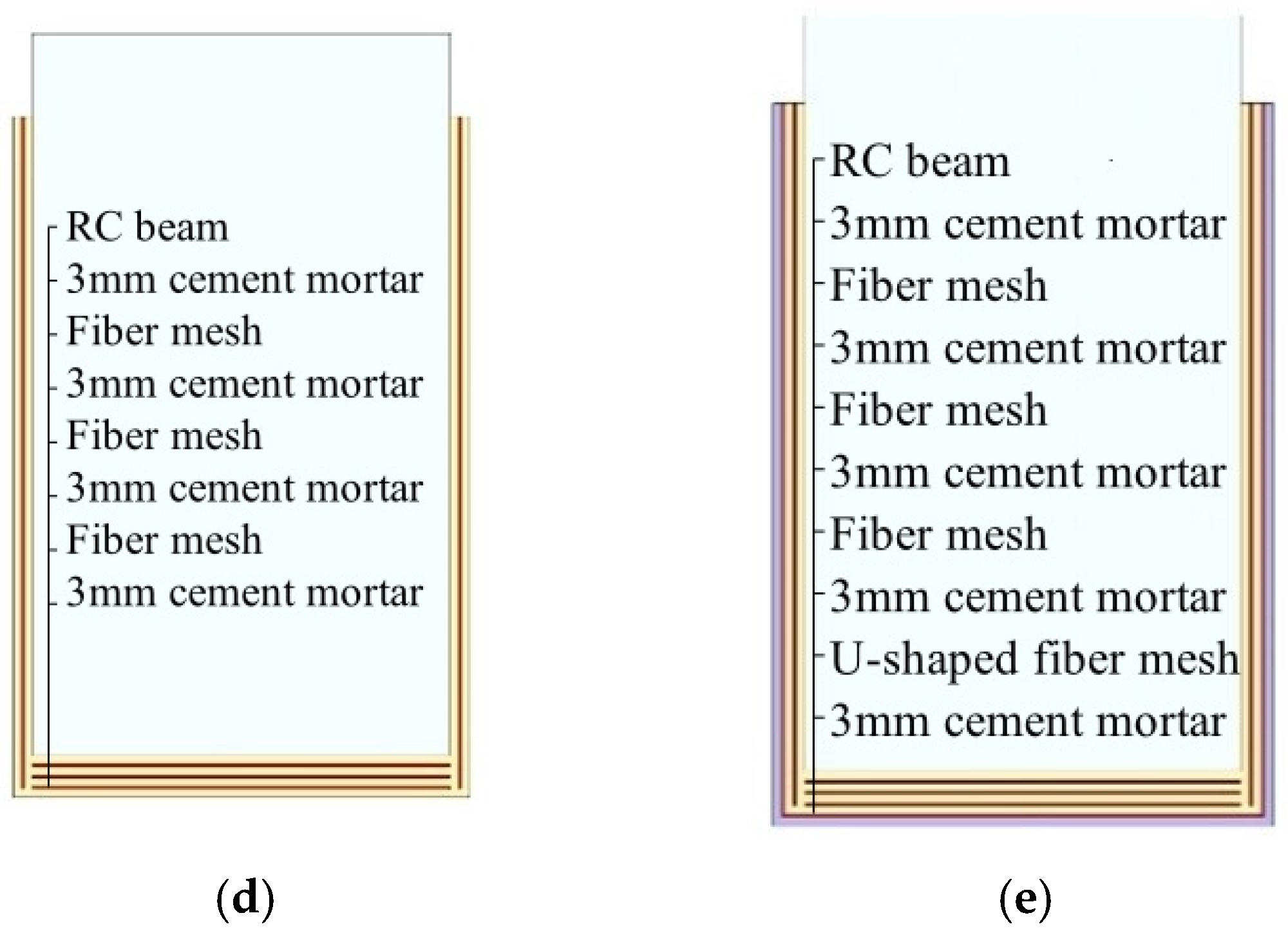
Figure 7.
Beam loading device diagram. (a) Schematic diagram of loading device; (b) loading device on-site diagram.
Figure 7.
Beam loading device diagram. (a) Schematic diagram of loading device; (b) loading device on-site diagram.

Figure 8.
Comparison of failure patterns of RC beams.


Figure 9.
Effect of temperature on the load–displacement curve of RC beams. (a) RC beams without CFM; (b) RC beam reinforced with one layer of CFM; (c) RC beam reinforced with three layers of CFM.
Figure 9.
Effect of temperature on the load–displacement curve of RC beams. (a) RC beams without CFM; (b) RC beam reinforced with one layer of CFM; (c) RC beam reinforced with three layers of CFM.


Figure 10.
Influence of the number of layers on the load–displacement curve. (a) RC beams at room temperature; (b) RC beams heated to 150 °C; (c) RC beams heated to 350 °C; (d) RC beams heated to 550 °C.
Figure 10.
Influence of the number of layers on the load–displacement curve. (a) RC beams at room temperature; (b) RC beams heated to 150 °C; (c) RC beams heated to 350 °C; (d) RC beams heated to 550 °C.

Table 1.
Mix proportions of concrete.
| Components | Water | Cement | Sand | Aggregate | Fly Ash | Mineral Powder | Admixture |
|---|---|---|---|---|---|---|---|
| Dosage (kg/m3) | 175 | 228 | 784 | 1083 | 70 | 60 | 8.6 |
Table 2.
Mechanical properties of steel bars.
| Rebar Diameter (mm) | Temperature (°C) | Yield Strength (MPa) | Ultimate Strength (MPa) |
|---|---|---|---|
| 8 | Room temperature | 446.30 | 620.52 |
| 150 | 428.54 | 608.08 | |
| 350 | 415.21 | 595.74 | |
| 550 | 391.92 | 569.86 | |
| 12 | Room temperature | 433.47 | 599.35 |
| 150 | 427.81 | 586.88 | |
| 350 | 420.56 | 583.42 | |
| 550 | 406.94 | 575.46 |
Table 3.
Mechanical properties of CFM.
| Elastic Modulus (kN/mm2) | Weight of Fibers in the Direction of Force (g/m2) | Ultimate Failure Load of Each Bundle of Fibers (N) |
|---|---|---|
| 230 | 80 (both directions) | ≥3200 |
Table 4.
Grouping of design components.
| Component Number | Heating Temperature (°C) | Layers of CFM |
|---|---|---|
| T20-0 | Room temperature | 0 |
| T20-1 | Room temperature | 1 |
| T20-3 | Room temperature | 3 |
| T150-0 | 150 | 0 |
| T150-1 | 150 | 1 |
| T150-3 | 150 | 3 |
| T350-0 | 350 | 0 |
| T350-1 | 350 | 1 |
| T350-3 | 350 | 3 |
| T550-0 | 550 | 0 |
| T550-1 | 550 | 1 |
| T550-3 | 550 | 3 |
Note: T20 represents the room-temperature group beam; the following (0, 1, 3) represent the number of CFM layers of the RC beam.
Table 5.
Mechanical properties of RC beams.
| Beam Number | Cracking Load (kN) | Ultimate Load (kN) | Ultimate Displacement (mm) |
|---|---|---|---|
| T20-0 | 18.2 | 87 | 28.9 |
| T20-1 | 24 | 108 | 25.2 |
| T20-3 | 26 | 115 | 20.3 |
| T150-0 | 16.4 | 85 | 26.2 |
| T150-1 | 22 | 102 | 24.7 |
| T150-3 | 25 | 112 | 20.1 |
| T350-0 | 16.3 | 82 | 22.9 |
| T350-1 | 21.4 | 98 | 21.7 |
| T350-3 | 24 | 105 | 22 |
| T550-0 | 15.5 | 75 | 18.8 |
| T550-1 | 16.8 | 90 | 15.4 |
| T550-3 | 18.6 | 95 | 25.2 |
Disclaimer/Publisher’s Note: The statements, opinions and data contained in all publications are solely those of the individual author(s) and contributor(s) and not of MDPI and/or the editor(s). MDPI and/or the editor(s) disclaim responsibility for any injury to people or property resulting from any ideas, methods, instructions or products referred to in the content. |
© 2024 by the authors. Licensee MDPI, Basel, Switzerland. This article is an open access article distributed under the terms and conditions of the Creative Commons Attribution (CC BY) license (https://creativecommons.org/licenses/by/4.0/).
Share and Cite
MDPI and ACS Style
Cheng, J.; Wang, H.; Xu, Z.; Yuan, G.; Li, Q. Mechanical Properties of Fire-Damaged RC Beams Reinforced with Carbon Fiber Mesh. Buildings 2024, 14, 1166. https://doi.org/10.3390/buildings14041166
AMA Style
Cheng J, Wang H, Xu Z, Yuan G, Li Q. Mechanical Properties of Fire-Damaged RC Beams Reinforced with Carbon Fiber Mesh. Buildings. 2024; 14(4):1166. https://doi.org/10.3390/buildings14041166
Chicago/Turabian StyleCheng, Jinsheng, Hao Wang, Zhisong Xu, Guanglin Yuan, and Qingtao Li. 2024. "Mechanical Properties of Fire-Damaged RC Beams Reinforced with Carbon Fiber Mesh" Buildings 14, no. 4: 1166. https://doi.org/10.3390/buildings14041166
Note that from the first issue of 2016, this journal uses article numbers instead of page numbers. See further details here.