4.5.1. Prefabricated Bottom-Plate Specimens
For the prefabricated specimen CDBP4812, the initial reverse camber was 15 mm. When the external load reached 2.45
, the reverse camber basically disappeared, and the bottom plate was laid down in a horizontal position. Prior to the load reaching 6.13
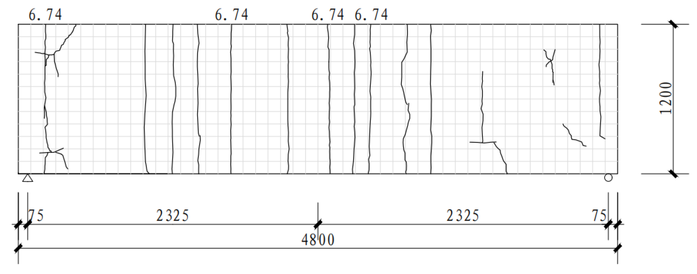
, no visible cracks appeared in the concrete at the bottom of the plate. The deflection increased slowly with each level of loading, and the change in rigidity was not obvious. When the load was increased to 6.74
, four through-cracks with a width of 0.2 mm uniformly appeared in the midspan of the underside of the bottom plate, extending upward along the side of the plate to 1/3–2/3 of its height. When the load was increased to 10.42
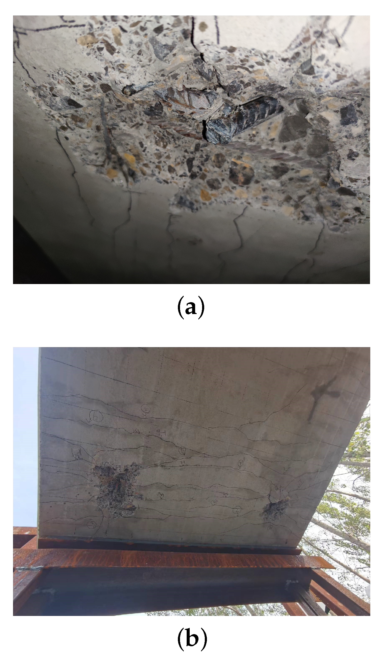
, the number of bottom cracks increased, with the cracks extending upward along the side of the bottom plate to 1/2–3/4 of its height. Punching shear failure occurred between the B-side web reinforcement bar and the concrete, and the upper-chord rectangular steel tubes buckled (
Figure 6a,b), leading to the cessation of loading. The distribution of cracks at the bottom of specimen CDBP4812 is shown in
Figure 7. During the loading process, no brittle fracture occurred in the prestressing steel, and there was no out-of-plane instability in the upper-chord rectangular steel tubes or the web reinforcement bars.
For specimen CDBP9012, the initial reverse camber was 8 mm. When the external load reached 1.96
, the reverse bow basically disappeared, and the bottom plate became horizontal. Prior to the load reaching 4.58
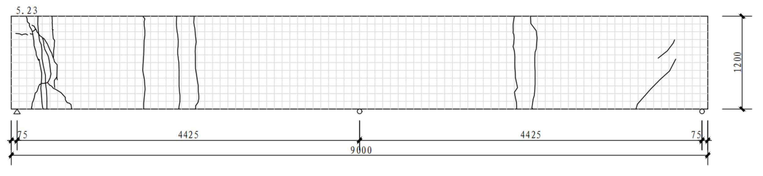
, no visible cracks appeared in the concrete at the bottom of the plate, the deflection increased little at each loading level, and the change in rigidity was not obvious. When the load was applied to 5.23
, a through-crack with a width of 0.1 mm appeared on the underside of the base plate, extending upward along the side of the plate to 1/3–2/3 of its height. When the load was increased to 8.50
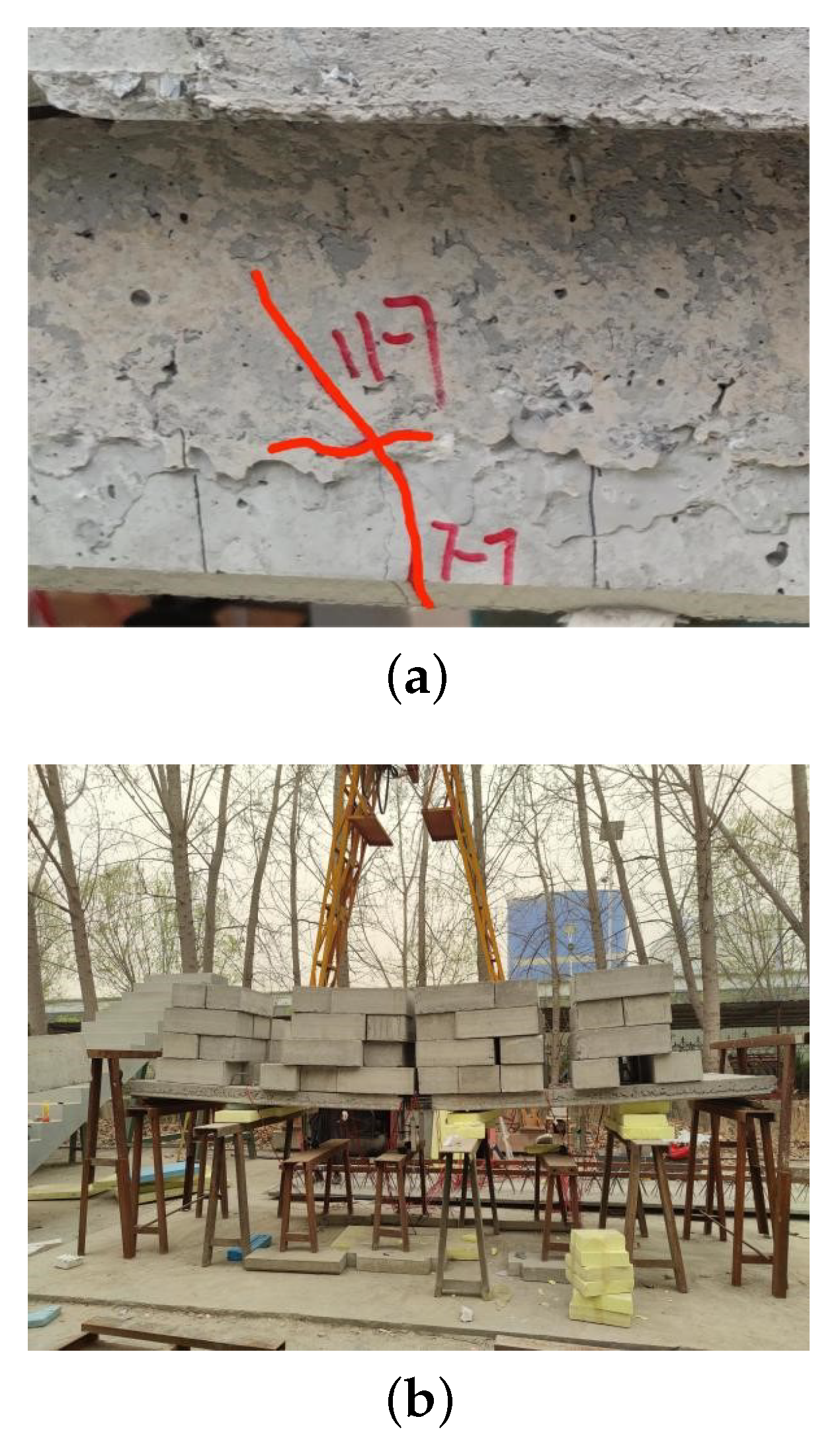
, multiple through-cracks appeared at the bottom of the plate, with the cracks extending upward to 1/2–3/4 of the plate’s height. Delamination damage occurred in the reinforcement of the web reinforcement bars on the A-side (
Figure 8a,b), leading to the cessation of loading. The distribution of cracks at the bottom of specimen CDBP9012 is shown in
Figure 9. During the loading process, no brittle fracture occurred in the prestressing steel, and there was no out-of-plane instability in the upper chord rectangular steel tubes or the web reinforcement bars.
For specimen CDBK9012, the initial reverse camber was 53 mm. When the external load reached 4.58
, the reverse camber basically disappeared, and the bottom plate became horizontal. When the load was applied to 11.11
, a through-crack with a width of 0.1 mm appeared on the upper surface of the middle support of the specimen (
Figure 10a). When the load was increased to 13.73
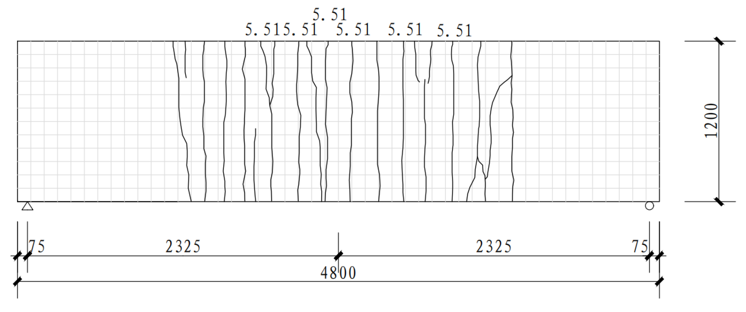
, two through-cracks appeared on the underside of the specimen, extending upward along the side of the base plate to 1/2–3/4 of its height. When the load increased to 17.32
, multiple through-cracks appeared at the bottom of the plate, with the cracks extending upward to 1/2–3/4 of the plate’s height, and the web reinforcement bars buckled (
Figure 10b), leading to the cessation of loading. The distribution of cracks at the bottom of specimen CDBK9012 is shown in
Figure 11. During the loading process, no brittle fracture occurred in the prestressing steel, and there was no out-of-plane instability in the upper chord rectangular steel tubes or the web reinforcement bars.
The two specimens, CDBP9012 and CDBK9012, have the same dimensions, but the crack distributions are different due to their different structural failure conditions. As mentioned above, the end of loading of sample CDBP9012 was signaled by the delamination damage of the web reinforcement on the A side. During the loading process, the weld joint connecting the web reinforcement to the A side of the bottom plate became loose, resulting in reduced rigidity and the appearance of cracks in the center of the A side. Upon completion of the loading process, the weld joint that connected the web reinforcement on side A of the bottom plate fractured, the rigidity of side A of the bottom plate was drastically reduced, and the concrete in the area of side A crumbled. So the crack distribution clearly indicates that the cracks are predominantly concentrated on side A (the left side). The end of the loading of sample CDBK9012 was signaled by the flexure of the web reinforcement on the B side. During the loading process, no structural fracture yielding occurred, and the rigidity of the whole structure remained almost unchanged, and the cracks were normally distributed on the plate. Upon completion of the loading process, the web reinforcement on the B side (right side) of the bottom plate buckled, which reduced the rigidity of that side and caused cracks to concentrate there.


