1. Introduction
Traditional Chinese residential buildings, being the earliest architectural type, are closely connected with human life. They directly reflect the local residents’ living environment and conditions, showcasing regional characteristics. Taking northern China as an example, its traditional residential structures predominantly rely on timber frames for structural support, supplemented by thick walls made of fired clay bricks. The cross-sectional dimensions of the brick walls far exceed the diameter of the timber columns, with timber frames typically embedded within the walls. Studies [
1,
2,
3] have found that infill walls have poor out-of-plane bending resistance and are prone to brittle failure [
4]. Under seismic loading, the phenomenon of “the wall collapsed but the house stands” is exhibited, as shown in
Figure 1. Therefore, enhancing the collaborative performance of timber frames and brick walls to mitigate the out-of-plane brittle failure caused by poor connections in the brick walls is an urgent issue to address.
In recent years, scholars have conducted extensive scientific research on the mechanical performance and deformation characteristics of the load-bearing components in traditional residential buildings, yielding fruitful academic achievements. Pawan [
5] studied the mechanical performance of unreinforced masonry under various loading combinations in plane and out of plane by establishing finite element models. The results showed that when the aspect ratio and slenderness ratio of the walls exceeded 20 and 2.0, respectively, the damage in plane significantly reduced the out-of-plane bearing capacity. Hamed [
6] proposed a theoretical analysis of full-size masonry walls reinforced with strips, considering the behavior of various materials, interfaces, and components across the entire loading range. Experimental validation confirmed the accuracy of the theory. Shen [
7] reinforced earth- and rubble-filled walls with polypropylene mesh and cement mortar, finding that all the reinforced walls showed significant improvements in their out-of-plane lateral bearing capacity and stiffness compared to the unreinforced walls. In a study of out-of-plane loading methods for walls, Priestley [
8] proposed using airbags to apply uniformly distributed horizontal loads to simulate seismic loads. This method addresses the potential reliability issues associated with using hydraulic actuators for point and line out-of-plane loading [
9,
10].
Some scholars have studied the collaborative performance of timber frames and walls. Yohei [
11] conducted experiments to investigate the pull-out failure of timber beams and masonry and performed a numerical analysis. The experiments showed that the compressive stress state of the wall and the grouting at the masonry interface effectively improved the friction between the masonry and the timber. Yuan [
12], through a field test of their dynamic characteristics and finite element analysis, concluded that the overall seismic stiffness of ancient timber frame buildings is mainly due to their walls. Paúl [
13] conducted cyclic lateral loading tests on eight lightweight timber-frame shear wall components to study their cyclic lateral performance under axial compression and in-plane bending moments. The study showed an improvement in the lateral performance of the walls, with increased stiffness, an increased bearing capacity, and increased energy dissipation. Vieux [
14] investigated the mechanical performance of timber frame filled wall structures. It was found that infill walls have a small impact on the structural bearing capacity but significantly influence the initial stiffness of the structure.
In summary, the research by domestic and international scholars has primarily focused on load-bearing components such as the brick walls and timber frames themselves. However, there is limited research on the collaborative performance of timber frames and walls, with only an understanding of their individual ability to withstand external loads. There is a lack of knowledge regarding the mechanical performance indicators for their combined action, and the influence of metal connectors on their collaborative performance has been scarcely studied. Therefore, building upon the existing research, this paper aims to address the relatively poor collaborative performance between timber frames and brick walls. A metal connector is designed and fabricated to enhance the collaborative performance. Furthermore, finite element simulations are conducted on one set without metal connectors and three sets with different numbers of metal connectors placed at various positions. The effects of different metal connector configurations on the out-of-plane damage patterns, deformation characteristics, and shear distribution of the timber frame–wall system are analyzed.
2. Materials and Methods
2.1. The Design of the Metal Connectors
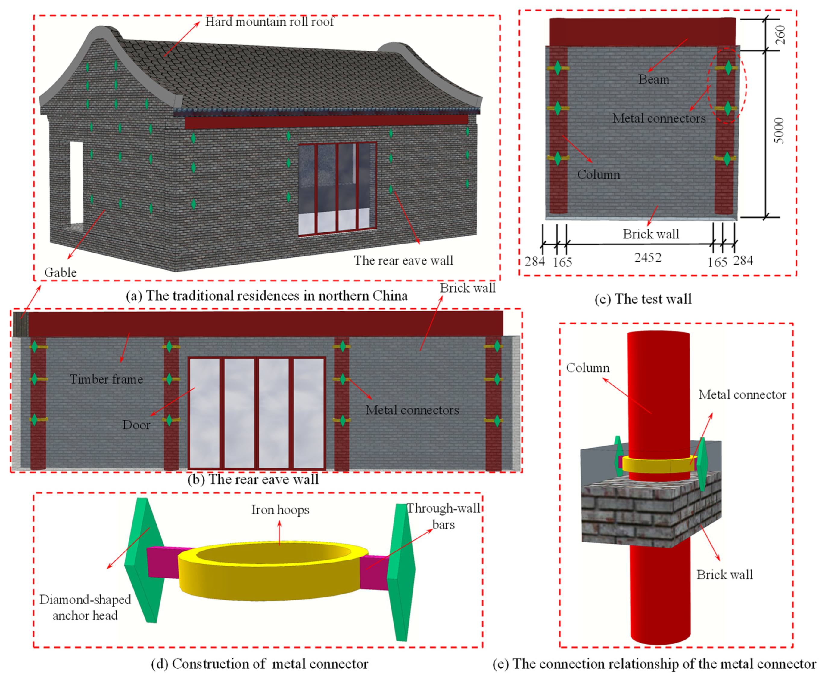
To enhance the out-of-plane collaborative performance of the timber frame and the wall, a metal connector was proposed and designed, primarily composed of a diamond-shaped anchor head, through-wall bars, and iron hoops (
Figure 2d). The dimensions of the metal connector are illustrated in
Figure 3, where “r” represents the column diameter of 330 mm, and “R” represents the outer diameter of the iron hoops of 360 mm. The positional relationship between the metal connector, the column, and the brick wall is depicted in
Figure 2e, where the iron hoops are welded to the corresponding positions on the timber columns. Subsequently, the diamond-shaped anchor heads at both ends are connected by the through-wall bars, with the diamond-shaped anchor head ends tightly against the wall surface. The distribution of the metal connectors shows a gradually denser state from bottom to top. A 3D structural diagram of a typical traditional residence in northern China equipped with metal connectors is shown in
Figure 2a. Traditional residences mainly consist of gable walls, timber frames, roofs, and rear eave walls. The connection between the columns and the walls is facilitated by the metal connectors for out-of-plane tension. The rear eave wall in
Figure 2b is primarily composed of timber frames, brick walls, metal connectors, and doors. The corner columns deviate from the gable wall, with the gable wall and the door serving as boundaries, selecting both sides of the timber frame–brick wall system of the rear eave wall as the research object, the model dimensions are as shown in
Figure 2c.
2.2. The Layout of the Metal Connectors
Based on different metal connector distributions, four sets of traditional residential wall models were designed: MC-1 had metal connectors at locations 1, 2, and 3; MC-2 had metal connectors at locations 1 and 2; MC-3 had metal connectors at locations 2 and 3; and MC-4 had no metal connectors, as can be seen in
Figure 4. Location 3 was positioned 2500 mm above the base of the brick wall, with equidistant spacing of 1000 mm between each location.
2.3. Loading Regime
From reference [
8], a uniformly distributed load was applied to simulate the out-of-plane mechanical behavior of the timber frame–wall system due to the inertial forces generated by the self-weight of the brick wall under seismic excitations. Load control was employed, with an increment of 1 kPa in the out-of-plane pressure applied at each level, equivalent to an increment of 3.0 kN in the out-of-plane load on the specimen. The load was sustained for 2 s after each level of loading until failure occurred in the out-of-plane direction of the brick wall, at which point the loading was stopped. The loading regime is illustrated in
Figure 5.
2.4. Measurement Point Layout Scheme
The displacement measurement points, as shown in
Figure 6, were positioned at lateral intervals of 613 mm on the left half of the wall and vertical intervals of 1200 mm to capture the out-of-plane deformations at different locations of the brick wall.
2.5. Material Mechanical Property Testing
2.5.1. Mechanical Properties of Pinus Sylvestris
To mitigate any variability in the timber properties, 12 standard specimens were prepared for each group [
15], and the average values of the data from each group were calculated to obtain various mechanical property indicators for the timber. The mechanical property tests for the timber are depicted in
Figure 7, while the performance indicators for Chinese red pine wood are presented in
Table 1.
2.5.2. Properties of the Fired Clay Bricks
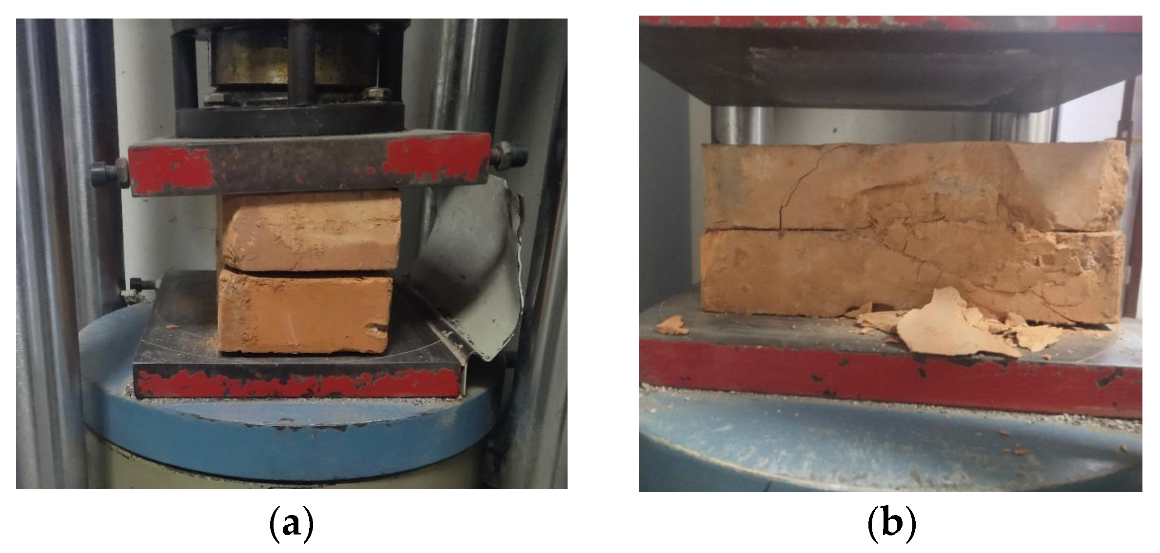
To mitigate any variability in the mechanical properties of the fired clay bricks, four standard specimens were tested for each group [
16], and the average values of each group’s data were taken to obtain the modulus of elasticity (E) and compressive strength (F) of the fired clay bricks. The testing equipment is illustrated in
Figure 8, and the mechanical indicators of the clay bricks are presented in
Table 2.
2.5.3. Properties of the Mortar
Normal cement mortar, composed of cement, sand, and water, was used to produce three standard mortar cube specimens with a side length of 70.7 mm [
17]. Their mechanical properties were determined using an electronic universal testing machine, as illustrated in
Figure 9. The compressive strength and failure load of the mortar are presented in
Table 3.
2.6. Finite Element Modeling Approach
A traditional residential timber frame–brick wall system consists of various materials, exhibiting complex material mechanical behaviors. Therefore, the finite element software ABAQUS v.2021 was utilized to model the walls. The modeling method for brick walls is well established. In this paper, the holistic modeling approach was adopted, wherein each brick, along with its surrounding 1/2 thickness of mortar, was modeled as a “composite block”. Three-dimensional solid elements were employed for the modeling. The brick wall adopted the concrete damage plasticity model provided in ABAQUS [
18], with the model parameter specifications presented in
Table 4 [
19]. Both the steel reinforcement and timber were modeled using bilinear models. Poisson’s ratio for the masonry was set to 0.2 [
20].
The interaction between the composite blocks and the interface between the brick wall and the timber frame was simulated using a surface-based cohesive contact behavior model: the cohesive behavior of the interface first becomes active, and when the stress at the interface reaches the cohesive strength limit, damage begins to occur, and the cohesive strength begins to degrade, allowing the onset of tangential friction behavior. After a complete loss of cohesion, the interface only resists shear stress through frictional forces, with a friction coefficient of 0.70 for the composite blocks [
21]. To capture the evolution of transverse and vertical cracks between the composite blocks, i.e., the “traction and separation” behavior between the brick units [
22], the simulation modeled the damage and fracture behavior between the interfaces of the composite bricks. The mechanical parameters of the contact surface are presented in
Table 5.
2.7. Model Establishment and Parameter Selection
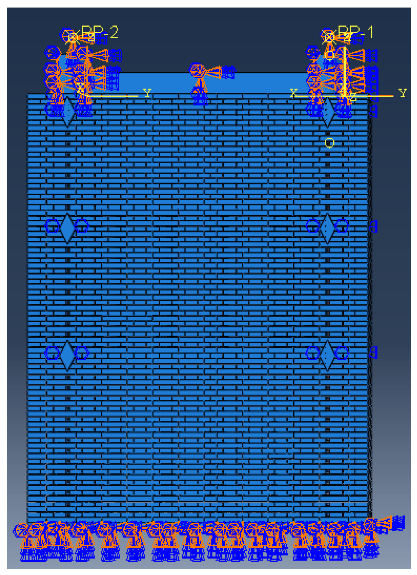
Taking the traditional residential timber frame–brick wall system as the research object, one group without metal connectors and three groups with different numbers of metal connectors placed at various positions in traditional residential wall models were established. Taking specimen MC-1 as an example, as shown in
Figure 10.
During the modeling process using the finite element software ABAQUS, the bottom of the wall and the column were fixed-constrained, while the top of the column was restrained through binding to reference points RP-4 and RP-2, respectively. The reference points were fixed-constrained (
Figure 10), and a uniformly distributed load was applied to the wall surface inside the timber frame. Regarding the contact relationship, binding connections were used between the metal hoops and the columns, and the mechanical parameters of the contact between the composite masonry blocks were referenced from
Table 5.
3. The Methods of Finite Element Modeling
3.1. Verifying the Establishment of the Model
The experimental results from reference [
23] were utilized to validate the damage criteria and surface contact behavior of the composite masonry blocks involved in the finite element model. The W3 specimen was selected for modeling to verify the rationality of the finite element model. The W3 specimen, representing a brick wall without floor loads and without metal connectors, is depicted in
Figure 11.
Using the finite element software ABAQUS, a wall model was established based on specimen W3, as shown in
Figure 12. Fixed constraints were applied at the bottom of the wall and the column, while a uniform load was applied to the wall surface to simulate airbag loading. The specific contact details were as follows: the tangential contact mechanical parameters of the composite blocks were referenced from the material test measurements in [
23], with tn0, ts0, and tt0 set to 230 kPa, 36.75 kPa, and 36.75 kPa, respectively. Normal contact was modeled as hard contact, with the composite block’s elastic modulus set to 800 MPa, its density set to 1700 kg/m
3, and Poisson’s ratio set to 0.2.
3.2. Validation of the Finite Element Models
During the loading process, when the load reached 51.3 kN, cracks began to appear at the top of the wall. With an increasing load, the cracks gradually extended downward from the top of the wall and began to bifurcate, extending towards the corners of the wall on both sides. When the load reached 54.0 kN, the out-of-plane load reached its maximum value, at which point the displacement at measuring point D3-3 reached 60 mm. Eventually, the wall failed, with its failure mode depicted in
Figure 13.
From
Figure 13a, it can be observed that the failure mode of the wall in the finite element simulation is an inverted “Y” shape, which is consistent with the experimental failure mode. The out-of-plane ultimate loads of specimen W3 from the experiment and the finite element simulation are shown in
Table 6, with an error of 2.5%.
The out-of-plane deformations of various measurement points on the wall are summarized in
Table 7. Here, Δ
cr represents the crack value at measurement point D3-3 where cracks appear, and
kΔ
cr denotes the crack value at measurement point D3-3 multiplied by
k.
Due to variations in the strength grade of the mortar and the properties of the bricks resulting from differences in the mortar mix batches used during construction, as well as the discreteness of the brick wall construction, the simulated values obtained using finite element analysis are slightly smaller than the experimental values, with a small error of 2.5%. This discrepancy also results in errors in the deformation of various measurement points on the wall, with relatively small errors in the out-of-plane deformations, with a minimum error of 7.1%. Therefore, the damage criteria and surface contact behavior of the model’s composite blocks were reasonably set and could be used for further numerical modeling and analysis.
4. Result Analysis
4.1. Failure Phenomena of Timber Frame–Wall
In model MC-1, as the load increased to 10.5 kN, vertical cracks appeared from the top of the brick wall, gradually extending downward, accompanied by an increase in the crack width. As the load further increased to 15.6 kN, horizontal cracks emerged in the middle and lower parts of the wall, with the displacements at points D2-2 and D8-8 measuring 25.6 mm and 3.15 mm, respectively. With continued loading, the vertical cracks in the middle of the wall widened. At 29.7 kN, the wall failed due to excessive deformation, with the maximum displacements at points D2-2 and D8-8 reaching 94.7 mm and 12.6 mm, respectively. The crack distribution of the wall is illustrated in
Figure 14a. The failure process and crack development in model MC-2 were similar to those observed in model MC-1.
For model MC-4, when the load reached 10.5 kN, vertical cracks initiated from the top of the wall, rapidly extending in length and width. As the load increased to 19.5 kN, the vertical cracks continued to propagate, and the diagonal cracks near the metal connectors rapidly extended downward, gradually intersecting with the vertical cracks. Concurrently, the bottom level of the bricks exhibited delamination, and the cracks in the wall formed a positive “Y” shape. At 22.9 kN, the vertical cracks reached their widest width, leading to wall failure, with the maximum displacements at points D2-2 and D8-8 measuring 82.5 mm and 17.1 mm, respectively. The crack distribution in the wall of model MC-4 is depicted in
Figure 14d.
4.2. Failure Modes
The comprehensive analysis of the failure phenomena in the various models reveals the significant role played by the metal connectors at position 1 in enhancing the synergy between the wall and the timber frame, impacting the failure phenomena and modes.
After the wall cracks, the out-of-plane deformation of the brick wall rapidly increases, with the cracks lengthening and widening.
The failure mode of the traditional residential timber frame–brick wall is complex, exhibiting both horizontal wall cracks with bending deformation and positive “Y”-shaped cracks. This complexity arises from the strong lateral constraints at the bottom and sides of the brick wall, while the constraints at the top, particularly between the bricks and the beam, are weaker. Removing the metal connection at position 1 further weakens the top wall’s restraint. The diagonal cracks in the brick wall at position 1 continue to develop, gradually intersecting with the vertical cracks in the wall, ultimately forming a positive “Y”-shaped crack.
4.3. Out-of-Plane Deformation Characteristics
The brick wall is restrained by the timber frame, resulting in significant differences in the out-of-plane deformation characteristics between the central wall and the column-side wall. Thus, the out-of-plane lateral displacements in the vertical direction of the central brick wall and the column-side wall under different conditions are separately recorded. The vertical lateral displacement of the brick wall is illustrated in
Figure 15. Analyzing the maximum out-of-plane displacement points of the brick wall as the focus, the maximum lateral displacement Δu and the rate of the increase in the maximum lateral displacement γ for each specimen are presented in
Table 8. As the number of metal connectors increases, the maximum lateral displacement of the middle wall specimens increases, indicating an improved deformation capacity. Measurement points D1-1 to D3-3 and D10-10 to D8-8 are located at distances of 614 mm and 1863 mm, respectively, from the wall edge, measuring the vertical lateral displacement. The vertical distance between each measurement point is 1200 mm.
Along the height of the wall, the out-of-plane displacement initially increases and then decreases, with the largest displacement occurring in the middle of the wall, particularly at points D2-2 or D3-2. In
Figure 15a, for the models with metal connectors at the top of the wall, the deformation at the measuring points before loading is primarily linear, during the later stages of loading, significant nonlinear deformations is observed in the wall. This phenomenon indicates that initially the wall does not crack or undergo bending deformation out of plane. As the load increases, the out-of-plane deformation in the middle and upper parts of the wall becomes consistent, while the out-of-plane displacement at the top of the wall relatively decreases. Therefore, the wall and the timber frame can collaborate, with the beams restraining the out-of-plane deformation of the top of the brick wall, limiting its deformation.
The influence of the metal connectors on the lateral displacement of the central wall was significant. Compared to specimen MC-4, all the other specimens showed varying degrees of improvement in their lateral deformation capacity. Specifically, the lateral deformation capacity of the wall increased by 66.1% in specimen MC-1, by 41.0% in specimen MC-2, and by 82.5% in specimen MC-3. The addition of metal connectors at positions 1, 2, and 3 significantly enhanced the lateral deformation capacity of the wall. However, the introduction of metal connectors at positions 1 and 2 resulted in only a 41.0% increase in the lateral deformation capacity of the wall compared to specimen MC-4, indicating the relatively minor impact of the metal connectors at positions 1 and 2. Conversely, the metal connector at position 3 played a controlling role in the maximum lateral deformation capacity of the wall.
The timber frame restrains the brick wall, resulting in significant differences in the deformation characteristics between the central wall and the wall near the columns. Consequently, the lateral displacement of the central brick wall under different conditions in the horizontal direction is recorded separately. The lateral displacement of the brick wall in the horizontal direction is shown in
Figure 16. Taking the lateral displacement of the D8-9 measuring point on the wall near the column as the research object, the maximum lateral displacement Δv and the rate of the increase in the maximum lateral displacement η at the D8-9 measuring point for each specimen are shown in
Table 9.
In the horizontal direction, the out-of-plane displacement gradually increases from the column-side wall to the middle of the wall in the model. The restraining effect of the frame column at the wall edge limits the out-of-plane displacement of the column-side wall, resulting in weaker out-of-plane constraints in the middle of the wall. Therefore, the out-of-plane displacement between D5-6 and D3-2 in the wall further increases. As shown in
Figure 16, for models MC-1 and MC-2, the out-of-plane displacement at the points exhibits linear development, indicating that the points are on the same side of the cracks after cracking and there is no crack running through them. Models MC-3 and MC-4 exhibit some nonlinear characteristics, indicating the presence of cracks between the points, separating them. The deformation between each block of the wall is not linearly related. The diagonal cracks at position 1 of the wall extend towards the middle of the wall, eventually forming through cracks.
According to
Table 9, it is evident that the metal connectors had a significant impact on the lateral displacement of the column-edge walls. Compared to specimen MC-4, all the specimens showed an increase in the lateral deformation capacity of their column-edge walls to varying degrees. The lateral deformation capacity of the wall in specimen MC-1 increased by 45.8%, by 35.6% in specimen MC-2, and by 65.3% in specimen MC-3. The placement of metal connectors at positions 1, 2, and 3, as well as at solely positions 2 and 3, significantly enhanced the lateral deformation capacity of the column-edge walls. Compared to specimen MC-4, adding metal connectors at positions 1 and 2 only increased the lateral deformation capacity of the column-edge walls by 35.6%. Therefore, the influence of the metal connectors at positions 1 and 2 on the lateral deformation capacity of the specimen walls was relatively small, while the metal connectors at position 3 played a controlling role in the ultimate lateral deformation capacity of the walls.
According to three measurement points, D8-8, D5-5, and D3-3, at the top of the wall, the out-of-plane displacement from the column-side wall to the middle of the wall was recorded to investigate the influence of the top wall metal connectors on the out-of-plane deformation of the wall and their impact on the collaborative performance of the timber frame and the wall. The summarized deformations of the brick wall at the measurement points are presented in
Table 10. And the time unit used in
Table 10 is seconds.
From
Table 10, it is evident that the metal connector at position 1 significantly reduced the out-of-plane displacement of the top of the wall, with a maximum reduction of up to 84.6%. The effect on the out-of-plane displacement of the wall’s middle section was relatively minor, with a minimum reduction of 7.2%. This indicates that the metal connectors at position 1 enhanced the overall integrity of the traditional residential walls and effectively improved the collaborative performance of the brick wall and the timber frame. In summary, while the impact of the metal connectors at position 1 on the ultimate lateral deformation capacity was minimal, they substantially reduced the out-of-plane deformation of the top brick wall, thereby effectively decreasing the wall’s tendency to rock outward. Consequently, the out-of-plane displacement of the wall significantly decreased, delaying the development of damage to the timber frame–brick wall structure.
4.4. Shear Force Distribution
The timber frame and the brick wall represent two different lateral resistance components. During loading, both components undergo damage, influencing changes in the column head force. The force measured at the column head is denoted as the column head shear force (
Vc), while the horizontal distributed load on the wall surface is represented as Vg. The relationship (
Vg–
Vc) for each specimen is shown in
Figure 17.
Figure 17 shows that initially the column head shear forces among the specimens are similar. However, in the later stages of loading, the arrangement of the metal connectors significantly influences the distribution of the shear forces at the column head. Compared to MC-4, specimen MC-1’s column head shear force increases by 6.22%, and specimen MC-3’s increases by 7.24%. Similarly, compared to MC-2, MC-1’s increases by 7.62%, and MC-3’s increases by 8.65%. This is because the uniformly distributed load on the brick can be transferred to the columns through the metal connectors positioned at locations 2 and 3, thereby increasing the horizontal shear force at the column heads. Consequently, the metal connectors at positions 2 and 3 establish a reliable connection between two different lateral-force-resistant components.
5. Discussion
During the research process, the arrangement of the connectors aimed to enhance the collaborative performance of the timber frames and walls, addressing the vulnerability of traditional residential brick walls to out-of-plane brittle failures caused by poor connections. Additionally, the study elucidated the influence patterns of the connectors on the shear forces at the heads of the traditional residential timber frame columns. It is noteworthy that the arrangement of the connectors was based solely on engineering experience and did not undergo parametric analysis.
The diamond-shaped anchor heads of the connectors limited the out-of-plane deformation of the brick wall. By connecting with the through-wall bars, they strengthened the connection between the brick walls and timber frames, significantly enhancing the brick wall’s deformation capacity.
6. Conclusions
This paper investigated the out-of-plane mechanical properties of the wooden structures in traditional residential walls, with a specific focus on enhancing reliable connections between timber frames and brick walls. The research delved deeply into studying the collaborative working mechanisms in timber frame–brick wall systems.
The presence of top metal connectors influenced the failure behavior and modes of the model. With top metal connectors, the brick walls developed vertically penetrating cracks, causing failure. Without metal connectors, the brick walls exhibited ‘Y’-shaped cracks, also leading to failure.
The influence of the metal connectors on the lateral displacement of the brick walls was significant. Compared to specimen MC-4, the lateral displacement capacity of the MC-1 wall increased by 66.1%, MC-2 by 41.0%, and MC-3 by 82.5%. This indicates that metal connectors can enhance the overall integrity of traditional residential brick walls, effectively improving the collaborative performance of brick walls and timber frames.
The metal connector at position 1 could significantly reduce the out-of-plane displacement of the brick wall at the connector location, with a maximum effect of up to 84.6%. The impact on the out-of-plane displacement in the middle of the brick wall was relatively minor, with a minimum reduction of 7.2%. It played a crucial role in enhancing the collaborative performance of the brick wall and the timber frame.
In the initial loading stages, there was minimal variation in the column head shear forces among the specimens. Yet, in later loading stages, the placement of the metal connectors significantly influenced the distribution of the shear forces at the column head. Specifically, during the later loading stages, there was an increased proportion of column head shear force observed in specimens MC-1 and MC-3. This suggests that the metal connectors at positions 2 and 3 effectively transferred the load to the column head, resulting in a notable increase in the horizontal shear force. This, in turn, established a reliable connection between two different lateral-force-resistant components (timber frame and brick wall), allowing them to collaboratively resist horizontal loads.
The connector at position 3 significantly enhanced the out-of-plane deformation capacity of the brick wall, while the impact of the connector at position 1 on the ultimate lateral deformation capacity was relatively minor. However, it significantly reduced the out-of-plane deformation of the top brick wall, effectively minimizing the outward deflection of the wall. Therefore, metal connectors should be installed at positions 1, 2, and 3 in traditional residential structures.
In further research, an in-depth analysis of the internal forces and stresses in the brick walls caused by the connectors can be conducted. Additionally, a detailed study of the arrangement of the connectors can be carried out to propose specific principles for the connector arrangement.
Author Contributions
The manuscript was written with the contributions of all authors. N.D.: Conceptualization, investigation, methodology, data curation, formal analysis, writing—original draft, writing—review and editing, and visualization. L.C. and L.F.: Investigation, methodology, data curation, and writing—review and editing. Y.L. and J.C.: Formal analysis, visualization, and review. All authors have read and agreed to the published version of the manuscript.
Funding
This research received no external funding.
Data Availability Statement
Data are available on request from the authors. The data that support the findings of this study are available from the corresponding author upon reasonable request.
Conflicts of Interest
Author Jiakun Chen was employed by the company Rail Transit Design Institute, China Railway Huatie Engineering Design Group Co., Ltd. The remaining authors declare that the research was conducted in the absence of any commercial or financial relationships that could be construed as a potential conflict of interest.
References
- Bridgman, P.W. Studies in Large Plastic Flow and Fracture; McGraw-Hill: New York, NY, USA, 1952. [Google Scholar]
- Bridgman, P.W.; Tracey, D.M. On the ductile enlargement of voids in triaxial stress fields. J. Mech. Phys. Solids 1969, 17, 201–217. [Google Scholar]
- Hancick, J.W.; Mackenzie, A.C. On the mechanisms of ductile failure in high-strength steels subjected to multi-axial stress-states. J. Mech. Phys. Solids 1976, 24, 147–160. [Google Scholar] [CrossRef]
- Zhou, T.; Liu, B. Experimental study on the shaking table tests of a modern inner-reinforced rammed earth structure. Constr. Build. Mater. 2019, 203, 567–578. [Google Scholar] [CrossRef]
- Agnihotri, P.; Singhal, V.; Rai, D.C. Effect of in-plane damage on out-of-plane strength of unreinforced masonry walls. Eng. Struct. 2013, 57, 1–11. [Google Scholar] [CrossRef]
- Xu, H.; Gentilini, C.; Yu, Z.; Wu, H.; Zhao, S. A unified model for the seismic analysis of brick masonry structures. Constr. Build. Mater. 2018, 184, 733–751. [Google Scholar] [CrossRef]
- Shen, Y.; Yan, X.; Jia, H.; Liu, H.; Wu, G.; He, W. Experimental evaluation of the out-of-plane behavior of a traditional timber frame with mud and rubble infill wall strengthened by a polypropylene band mesh on one side. Structures 2023, 58, 105392. [Google Scholar] [CrossRef]
- Priestley, M.J.N. Seismic behaviour of unreinforced masonry walls. Bull. N. Z. Soc. Earthq. Eng. 1985, 18, 191–205. [Google Scholar] [CrossRef]
- D’Ambra, C.; Lignola, G.P.; Prota, A.; Sacco, E.; Fabbrocino, F. Experimental performance of FRCM retrofit on out-of-plane behaviour of clay brick walls. Compos. Part B Eng. 2018, 148, 198–206. [Google Scholar] [CrossRef]
- Haddad, M.A.; Shaheen, E.; Parsekian, G.A.; Tilleman, D.; Shrive, N.G. Strengthening of a concrete masonry wall subject to lateral load with sprayed glass-fibre-reinforced polymer. Can. J. Civ. Eng. 2010, 37, 1315–1330. [Google Scholar] [CrossRef]
- Yohei, E.; Takanori, G. Pull-out test and numerical simulation of beam-to-wall connection: Masonry in earthen mortar and hardwood timber. Eng. Struct. 2023, 15, 115206. [Google Scholar]
- Yuan, J. Seismic analysis method considering wall participation for ancient timber frame buildings. J. Build. Struct. 2018, 39, 45–52. (In Chinese) [Google Scholar]
- Orellana, P.; Santa, M.H.; Almazan, J.L.; Estrella, X. Cyclic behavior of wood-frame shear walls with vertical load and bending moment for mid-rise timber buildings. Eng. Struct. 2021, 240, 112298. [Google Scholar] [CrossRef]
- Vieux-Champagne, F.; Sieffert, Y.; Grange, S.; Polastri, A.; Ceccotti, A.; Daudeville, L. Experimental analysis of seismic resistance of timber-framed structures with stones and earth infill. Eng. Struct. 2014, 69, 102–115. [Google Scholar] [CrossRef]
- GB/T 50329-2012; Ministry of Housing and Urban-Rural Development of the People’s Republic of China (MOHURD). Standard for Test Methods of Timber Structures. China Standard Industry Press: Beijing, China, 2012. (In Chinese)
- GB/T 50129-2011; Ministry of Housing and Urban-Rural Development of the People’s Republic of China (MOHURD). Standard Test Methods for Basic Mechanical Properties of Masonry. China Architecture & Building Press: Beijing, China, 2011. (In Chinese)
- JGJ/T 70-2009; Ministry of Housing and Urban-Rural Development of the People’s Republic of China (MOHURD). Standard Test Methods for Basic Mechanical Properties of Building Mortar. China Architecture & Building Press: Beijing, China, 2009. (In Chinese)
- ABAQUS. User’s Manual, Version 6.12; Dassaults Systemes Inc.: Pawtucket, RI, USA, 2012. [Google Scholar]
- Al-Ahdal, A.; Aly, N.; Galal, K. Simplified analytical models for partially grouted reinforced masonry shear walls. Eng. Struct. 2022, 252, 113643. [Google Scholar] [CrossRef]
- Buyukkaragoz, A.; Kopraman, Y. In-plane behaviour of masonry brick walls strengthened with mortar from two sides. Structures 2021, 29, 1627–1639. [Google Scholar] [CrossRef]
- Ge, J.Q.; Zhao, Q.; Ma, B.T. Static failure mechanism and performance index of brick wall (column)-wooden house frame ancient building. J. Build. Struct. 2023, 44, 56–64. (In Chinese) [Google Scholar]
- ABAQUS Inc. Abaqus Analysis User’s Manual; ABAQUS Inc.: Providence, RI, USA, 2016. [Google Scholar]
- Zhang, Y.Q.; Jiang, L.X.; Wang, Z.L. Out-of-plane behavior of brick wall of historical masonry structures. J. Build. Struct. 2022, 43, 177–190. (In Chinese) [Google Scholar]
Figure 1.
Common seismic damages to the walls in traditional timber residences. (a) Local collapse of the wall; (b) overall collapse of the wall.
Figure 1.
Common seismic damages to the walls in traditional timber residences. (a) Local collapse of the wall; (b) overall collapse of the wall.
Figure 2.
Architectural drawings in traditional residence.
Figure 2.
Architectural drawings in traditional residence.
Figure 3.
Dimensional diagram of the metal connector. (a) Top view; (b) front view.
Figure 3.
Dimensional diagram of the metal connector. (a) Top view; (b) front view.
Figure 4.
Distribution of connectors. (a) MC-1; (b) MC-2; (c) MC-3; (d) MC-4.
Figure 4.
Distribution of connectors. (a) MC-1; (b) MC-2; (c) MC-3; (d) MC-4.
Figure 5.
Loading protocol.
Figure 5.
Loading protocol.
Figure 6.
Layout of measurement points.
Figure 6.
Layout of measurement points.
Figure 7.
Mechanical performance test for timber. (a) The compressive strength, parallel; (b) the tensile strength, parallel; (c) the radial tensile strength, perpendicular; (d) compressive modulus of elasticity.
Figure 7.
Mechanical performance test for timber. (a) The compressive strength, parallel; (b) the tensile strength, parallel; (c) the radial tensile strength, perpendicular; (d) compressive modulus of elasticity.
Figure 8.
Compression test of fired clay brick. (a) Fired clay brick; (b) failure mode.
Figure 8.
Compression test of fired clay brick. (a) Fired clay brick; (b) failure mode.
Figure 9.
Compressive of test mortar. (a) Mortar; (b) mortar.
Figure 9.
Compressive of test mortar. (a) Mortar; (b) mortar.
Figure 10.
Wall model MC-1 of traditional residence.
Figure 10.
Wall model MC-1 of traditional residence.
Figure 12.
Finite element model.
Figure 12.
Finite element model.
Figure 13.
Failure mode. (a) Finite element simulation; (b) experiment.
Figure 13.
Failure mode. (a) Finite element simulation; (b) experiment.
Figure 14.
Failure modes. (a) MC-1; (b) MC-2; (c) MC-3; (d) MC-4.
Figure 14.
Failure modes. (a) MC-1; (b) MC-2; (c) MC-3; (d) MC-4.
Figure 15.
Vertical displacement deformation of the brick wall. (a) MC-1; (b) MC-2; (c) MC-3; (d) MC-4.
Figure 15.
Vertical displacement deformation of the brick wall. (a) MC-1; (b) MC-2; (c) MC-3; (d) MC-4.
Figure 16.
Horizontal displacement deformation of brick wall. (a) MC-1; (b) MC-2; (c) MC-3; (d) MC-4.
Figure 16.
Horizontal displacement deformation of brick wall. (a) MC-1; (b) MC-2; (c) MC-3; (d) MC-4.
Figure 17.
Distribution of column head shear force.
Figure 17.
Distribution of column head shear force.
Table 1.
Mechanical properties of Pinus sylvestris.
Table 1.
Mechanical properties of Pinus sylvestris.
| Longitudinal (MPa) | Transverse (MPa) |
|---|
| Tensile Strength | Compressive Strength | Shear Strength | Modulus of Elasticity | Compressive Strength | Modulus of Elasticity |
|---|
| 100.95 | 48.60 | 8.18 | 8772.92 | Tangential | Radial | Tangential | Radial |
| 3.80 | 4.11 | 147.02 | 468.02 |
Table 2.
Mechanical properties of fired clay brick.
Table 2.
Mechanical properties of fired clay brick.
| No | Compression Area (mm2) | Maximum Pressure (kN) | Compressive Strength (MPa) | Average Compressive Strength (MPa) | Standard Deviation | Coefficient (%) |
|---|
| 1 | 27,600 | 213.9 | 7.75 | 7.17 | 0.88 | 12.27 |
| 2 | 27,600 | 191.9 | 6.95 |
| 3 | 27,600 | 200.8 | 7.28 |
| 4 | 27,600 | 180.4 | 6.54 |
Table 3.
Mechanical properties of mortar.
Table 3.
Mechanical properties of mortar.
| No | Compression Area (mm2) | Maximum Pressure (kN) | Compressive Strength (MPa) | Average Compressive Strength (MPa) | Standard Deviation | Coefficient (%) |
|---|
| 1 | 4963 | 90.34 | 18.20 | 18.20 | 0.09 | 0.49 |
| 2 | 4963 | 91.35 | 18.41 |
| 3 | 4963 | 89.23 | 17.98 |
Table 4.
Parameters of concrete damage model.
Table 4.
Parameters of concrete damage model.
| Expansion Angle | Eccentricity | fb0/fc0 | K | Viscous Parameters |
|---|
| 36° | 0.1 | 2/3 | 2/3 | 1.16 |
Table 5.
Mechanical parameters of composite block contact surfaces.
Table 5.
Mechanical parameters of composite block contact surfaces.
| Coefficient of Friction | kn
(N/m3) | ks = kt
(N/m3) | tn0
(MPa) | ts0 = tt0
(MPa) | Gnc
(N/m) | Gsc
(N/m) |
|---|
| 0.75 | 8.2 × 10¹⁰ | 3.6 × 10¹⁰ | 0.602 | 0.096 | 14 | 160 |
Table 6.
Experimental and calculated ultimate load values of the wall.
Table 6.
Experimental and calculated ultimate load values of the wall.
| No | Ultimate Load |
|---|
| Experimental Value (kN) | Simulated Value (kN) | Error (%) |
|---|
| W3 | 55.4 | 54.0 | 2.5 |
Table 7.
Deformations at various points of the wall.
Table 7.
Deformations at various points of the wall.
| Point | D1-1 | D2-2 | D3-3 | D6-6 | D9-9 |
|---|
| Experiment (mm) | Simulation (mm) | Experiment (mm) | Simulation (mm) | Experiment (mm) | Simulation (mm) | Experiment (mm) | Simulation (mm) | Experiment (mm) | Simulation (mm) |
|---|
| Δcr | 0.6 | 0.5 | 6.9 | 6.1 | 8.0 | 7.9 | 4.6 | 4.2 | 2.7 | 2.3 |
| 2Δcr | 0.9 | 0.8 | 14.3 | 13.9 | 16.3 | 16.7 | 8.9 | 7.9 | 3.6 | 3.1 |
| 3Δcr | 1.3 | 1.1 | 19.9 | 18.5 | 24.1 | 23.0 | 12.7 | 11.5 | 4.3 | 3.8 |
| 4Δcr | 2.1 | 1.9 | 25.7 | 24.6 | 32.6 | 32.8 | 17.2 | 15.6 | 4.7 | 4.1 |
| 5Δcr | 2.6 | 2.4 | 31.4 | 32.6 | 40.6 | 37.7 | 21.1 | 19.6 | 4.9 | 4.2 |
| 6Δcr | 3.0 | 2.7 | 37.7 | 37.5 | 48.7 | 47.8 | 25.4 | 23.5 | 5.0 | 4.3 |
| Maximum error | 16.7% | 11.6% | 7.1% | 11.8% | 14.8% |
Table 8.
The ultimate lateral displacement of each specimen at vertical measuring points.
Table 8.
The ultimate lateral displacement of each specimen at vertical measuring points.
| Specimen | Position | Δu/mm | γ (%) |
|---|
| MC-1 | 1, 2, 3 | 88.16 | 66.1 |
| MC-2 | 1, 2 | 74.84 | 41.0 |
| MC-3 | 2, 3 | 96.83 | 82.5 |
| MC-4 | No | 53.09 | 0 |
Table 9.
The ultimate lateral displacement of each specimen at at horizontal measuring points.
Table 9.
The ultimate lateral displacement of each specimen at at horizontal measuring points.
| Specimen | Position | Δv/mm | η (%) |
|---|
| MC-1 | 1, 2, 3 | 17.20 | 45.8 |
| MC-2 | 1, 2 | 16.00 | 35.6 |
| MC-3 | 2, 3 | 19.51 | 65.3 |
| MC-4 | No | 11.80 | 0 |
Table 10.
Deformations of the top brick wall.
Table 10.
Deformations of the top brick wall.
| No | D3-3 | D5-5 | D8-8 |
|---|
| Time | Walls with Connections (mm) | Without Connections (mm) | Walls with Connections (mm) | Without Connections (mm) | Walls with Connections (mm) | Without Connections (mm) |
|---|
| 3.5 t | 7.01 | 8.35 | 2.82 | 6.87 | 0.57 | 3.69 |
| 7.0 t | 17.09 | 18.41 | 5.15 | 14.04 | 1.43 | 5.83 |
| 10.5 t | 27.96 | 31.07 | 6.76 | 21.86 | 3.15 | 7.99 |
| 14.0 t | 41.32 | 46.12 | 8.28 | 30.99 | 5.84 | 10.26 |
| 17.5 t | 52.63 | 63.49 | 9.64 | 40.62 | 8.13 | 12.84 |
| Collaborative performance | 7.2–17.1% | 58.8–76.3% | 36.7–84.6% |
| Disclaimer/Publisher’s Note: The statements, opinions and data contained in all publications are solely those of the individual author(s) and contributor(s) and not of MDPI and/or the editor(s). MDPI and/or the editor(s) disclaim responsibility for any injury to people or property resulting from any ideas, methods, instructions or products referred to in the content. |
© 2024 by the authors. Licensee MDPI, Basel, Switzerland. This article is an open access article distributed under the terms and conditions of the Creative Commons Attribution (CC BY) license (https://creativecommons.org/licenses/by/4.0/).


