
Adaptive Control of Chaotic Signals: Investigated by Simulation Software and Real Electronic Circuits


1
Graduate Institute of Automation and Control, National Taiwan University of Science and Technology, Taipei 10608, Taiwan
2
Department of Mechanical Engineering, National Chiao Tung University, Hsinchu 30010, Taiwan
3
Graduate Institute of Manufacturing Technology, National Taipei University of Technology, Taipei 10608, Taiwan
*
Author to whom correspondence should be addressed.
Actuators 2021, 10(11), 284; https://doi.org/10.3390/act10110284
Submission received: 31 August 2021
/
Revised: 16 October 2021
/
Accepted: 18 October 2021
/
Published: 25 October 2021
(This article belongs to the Special Issue Actuators in Robotic Control)
Abstract
:Chaotic behavior is complicated, sensitive, and has the feature of great variety, which are the most potential signals to be applied in data encryption, secure communication, medical information protection, etc. As a consequence, in this paper, we try to propose three different ways to show our data generating results step by step, which means it can be proved effectively and used in practice: (1) Chaotic solutions simulated by MATLAB, (2) chaotic motion drawn via electronic circuits software Multisim, and (3) chaotic signal implemented on real electronic circuits with breadboard. In advance, following the same design principal, the adaptive chaotic signal is also designed and presented in the end of this article for further study, which provides a more flexible and variable chaotic signal to enhance the encryption effectiveness. The experimental results are extremely close to the two simulation results and can definitely be technically transferred to real encryption application.
1. Introduction
In the last two decades, research in chaotic dynamic systems has received a great deal of interest among scientists from various kinds of fields [1,2,3,4,5,6], which is an interdisciplinary research topic and well-famous for its complicated behaviors and sensitivity with initial conditions. Therefore, researchers from different fields are all devoted to discovering the applications and extending the usages of the complex chaotic dynamics, such as engineering applications [7,8,9], fractional-order analysis [10,11,12], information processing [13,14], fault diagnosis [15,16,17], encryption and secure communication [18,19,20], and so forth. Furthermore, some research papers discuss the sinusoidal oscillation generation in the identification problem [21,22]. Additionally, some control strategies are applied to avoid oscillation systems, or in some cases, to generate oscillations to be used in identification problems [23,24].
The signals generated by chaotic systems have statistical properties similar to randomness, in spite of being deterministic. As a result, chaotic systems have been used for secure communication and different encryption systems to hide the important information signal in current years. This encryption technology has fruitful and high-potential applications in our technology-mobilized life, especially in commercial message communication, customer information transmit and protection, or mobile shopping. For example, K. Murali et al. proposed a chaos-based signal encryption scheme to transmit digital information signals by using the conventional synchronization of chaos and digital encryption approaches [25], which is an application of chaos to secure communications. N. Nguyen et al. designed a low-power circuit to further generate a chaos signal for data encryption [26], which attempts to hide the personal data by applying chaotic signals. J.J. Chen et al. developed a set of memristor-based hyper-chaotic circuits for image encryption, which is a very useful and interesting research on image protection using chaos circuits [27]. Moreover, G. Mohamed et al. discussed an improved chaos circuit cryptosystem system for medical image encryption and decryption [28], developing a four-dimensional chaotic system by electronic circuits. Additionally, Li et al. presented a chaos-based image data protection algorithm to further protect images stored in the cloud database [20]. Furthermore, H. T. Baby and B. R. Sujatha applied a chaos circuit to further realize voice and text encryption in 2020 [29], etc.
Consequently, generating a signal from chaotic systems in the studies of software as well as hardware are extremely important in these application fields. In this paper, we further propose three main ways to show our data generating results, which means it can be proved effectively and used in practice: (1) chaotic solutions simulated by MATLAB, (2) chaotic motion drawn via electronic circuits software Multisim, and (3) chaotic signals implemented on real electronic circuits with breadboard. Furthermore, in order to improve the usability of encryption via chaotic signals, in this article, we provide a set of adaptive chaotic signal generation as well, which is implemented through the same design principal mentioned above. The adaptive chaotic signal generated by electronic circuits actually provided a more flexible and valuable way to enhance the encryption effectiveness.
The organization of the rest of the paper is as follows. In Section 2, chaotic behavior expression of the four-dimensional Chen–Lee System is introduced. In Section 3, the implementation on electronic circuit-software simulation and hardware configuration are proposed for further comparison. In Section 4, adaptive synchronization of the four-dimensional Chen–Lee system on electronic circuits is given. In Section 5, conclusions are given to summarize the main contributions of this paper, which give a small reminder to our reader to catch the points in this article more easily.
2. Chaotic Behavior Expression of the Four-Dimensional Chen–Lee System
Before introducing the four-dimensional Chen–Lee system, let us take a look at the original Chen–Lee system [30]. Chen and Lee reported a new chaotic system in 2004, which is now called the Chen–Lee system, the expression of Euler equations for the motion of a rigid body with principal axes at the center of mass, which can be described by the following non-linear differential equations with three states:
where x1, x2, and x3 are system states, a, b, and c are system parameters. Chaotic behaviors of the system reveals when parameters set as a = 5, b = −10, c = −3.8. In the article, we add a feedback control equation to the Chen–Lee system mentioned in Equation (1), and it becomes a new four-dimensional system. This four-dimensional Chen–Lee system can be represented as follows:
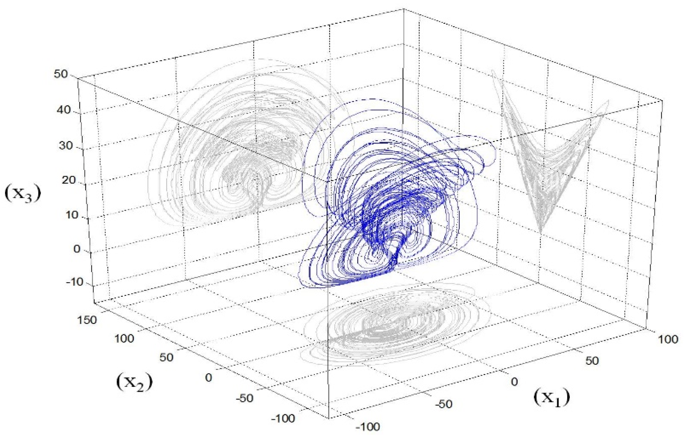
where x1, x2, x3, and x4 are system states, a, b, c, d, and r are system parameters. When the parameters are chosen as a = 5, b = 0.9, c = −10, d = −3.8, and r = −2, the new system shows complex and beautiful chaotic trajectory. A set of comprehensive chaotic motions are firstly developed and exhibited in Figure 1 in a 3-D way. Its three-axis projections express the 2-D phase portraits of x1 − x2, x1 − x3, x2 − x3, respectively.
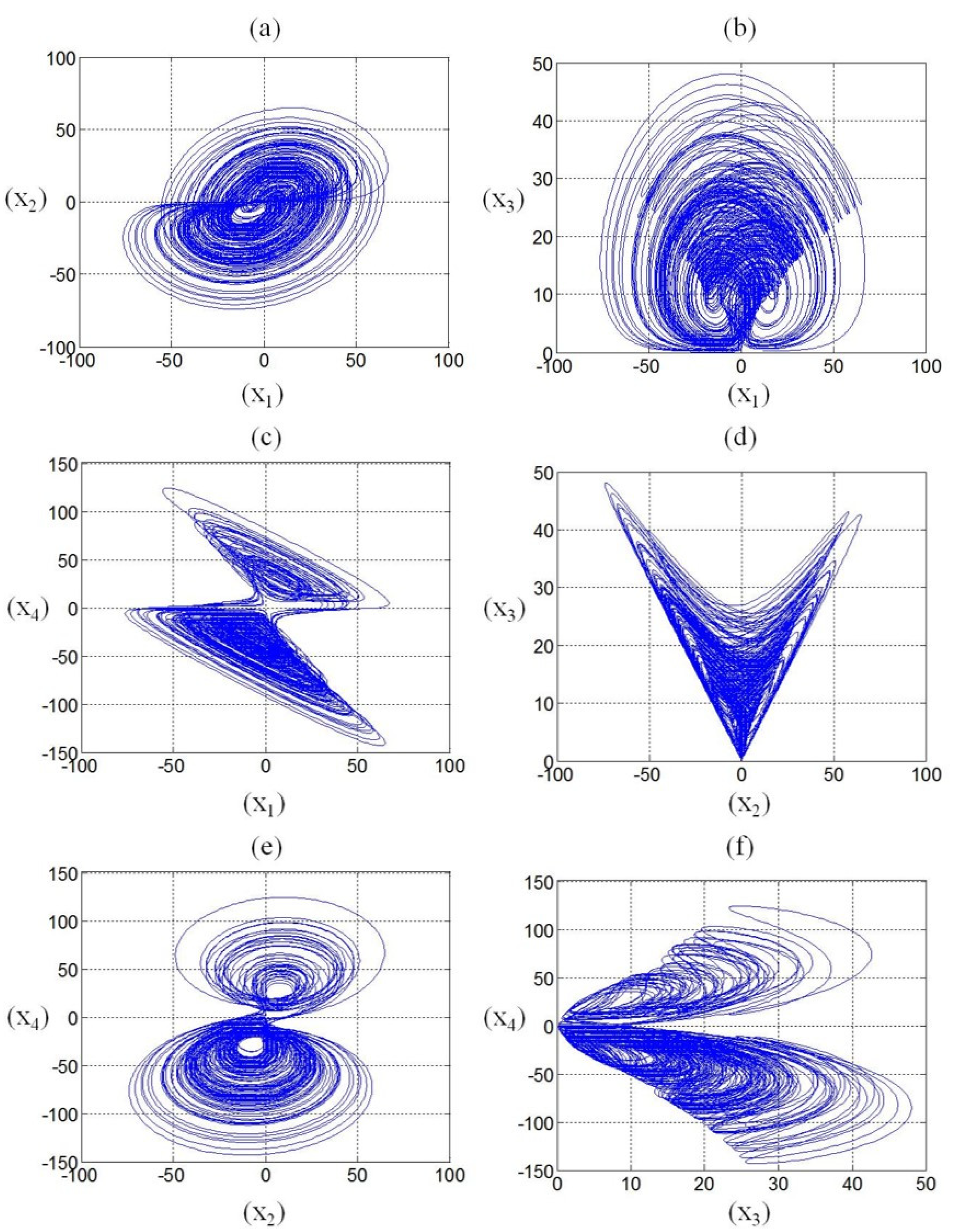
In order to have a better comparison with the chaotic behaviors on electrical circuits in the following section, complete information of the 2-D phase portraits is provided below in Figure 2.
3. Implementation on Electronic Circuit—Software Simulation and Hardware Configurations
In this part, chaotic behaviors of the four-dimensional Chen–Lee system introduced in the previous section will be realized on electronic circuits through simulation software testing and hardware design; the main electronic components include integrated amplifiers and inverting amplifiers.
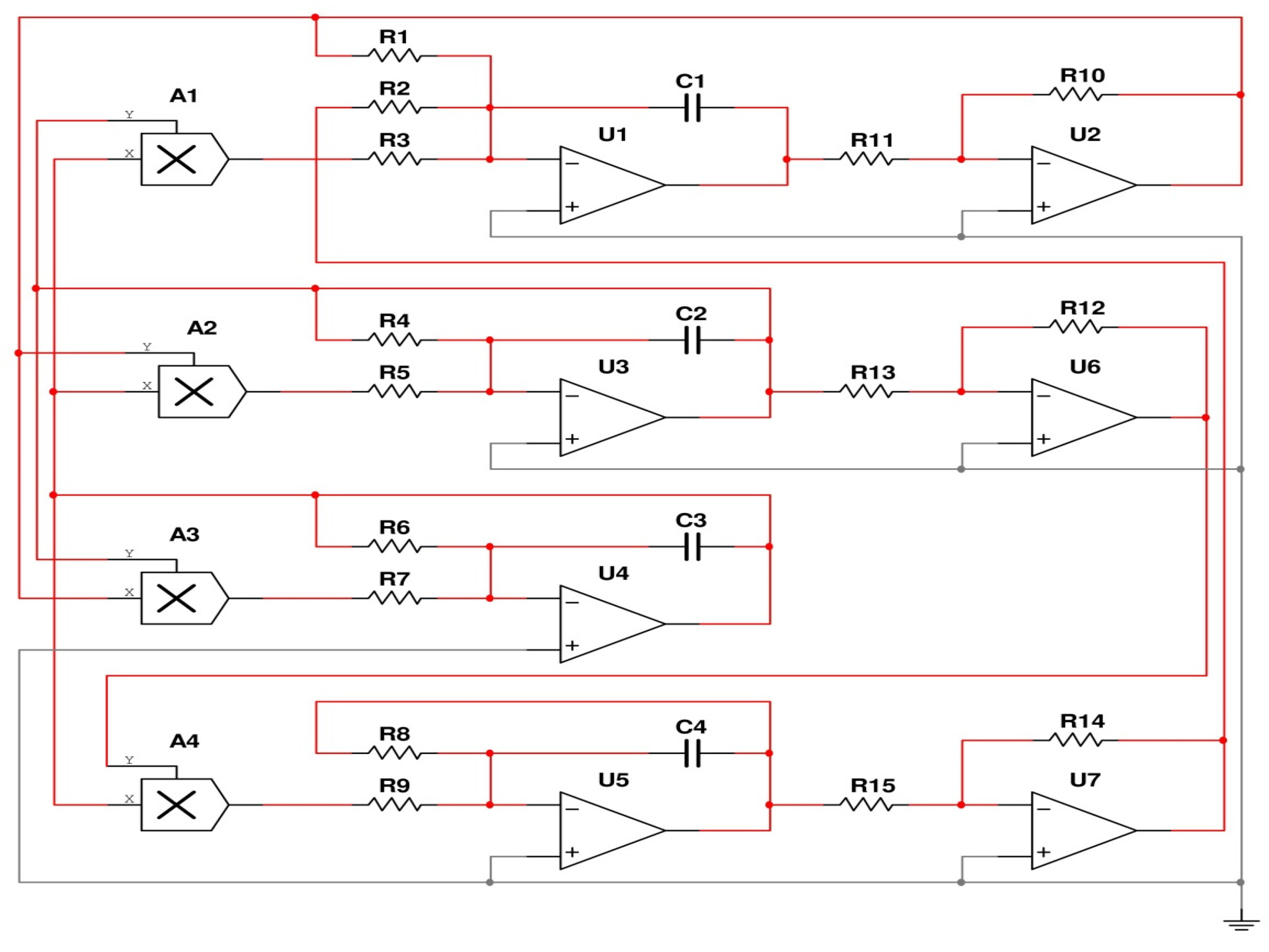
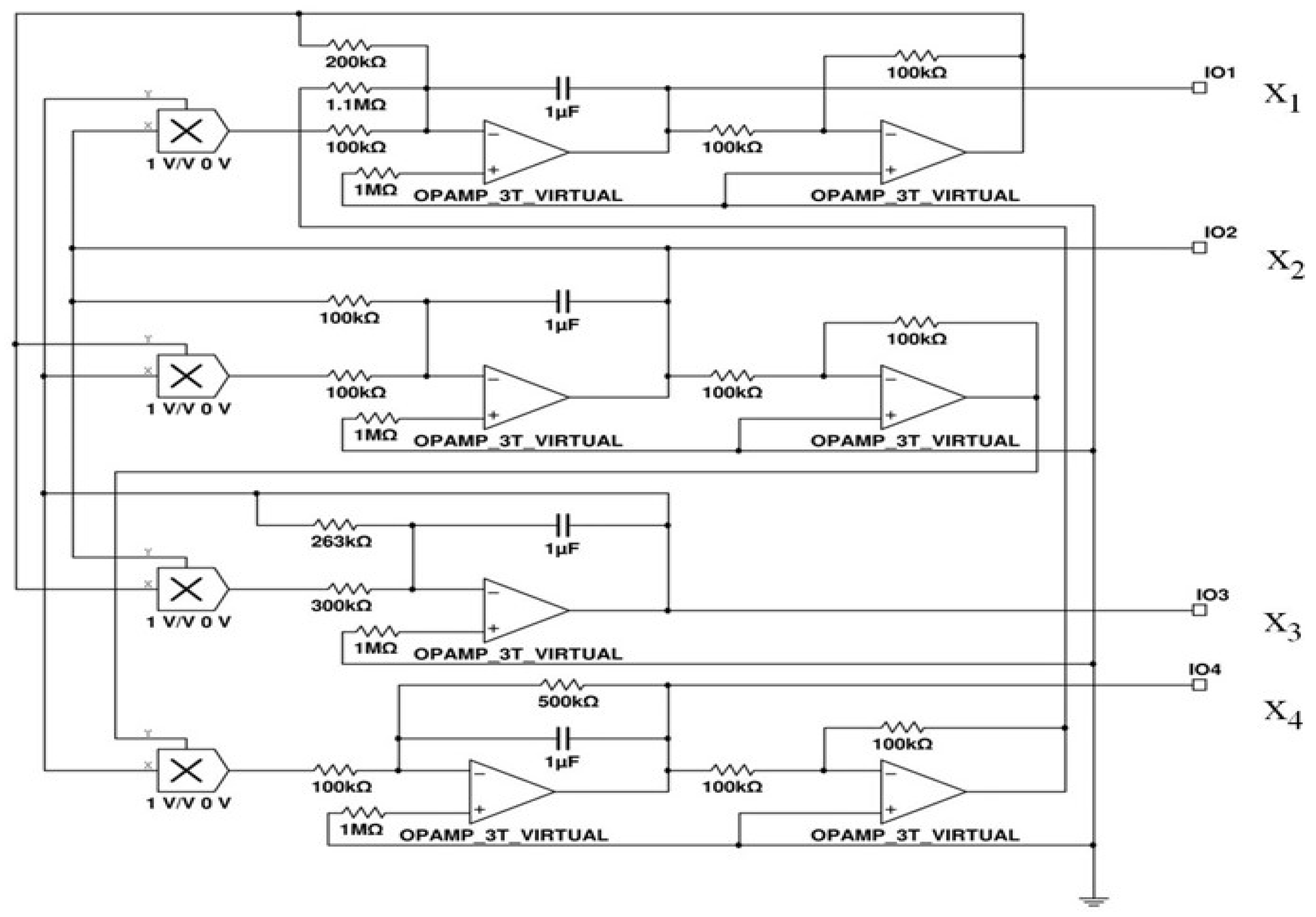
Before implementing on real electronic circuits, electronic circuit software was applied to simulate and investigate the effectiveness of our design. In this stage, we used the software Multisim (the latest version 11 in 2013). All the parameters and initial conditions were the same as the previous section. However, here, we have modified the value of capacitors to decrease the output voltage within a range from −12.0 to 12.0, and all the state value reduced tenfold in circuit simulation. The chaotic circuit configuration diagram is shown in Figure 3, and the governing integral equation of the circuit can be written as Equation (3), where V refers to the voltage of the corresponding states, R and C indicate the resistance and capacitance:
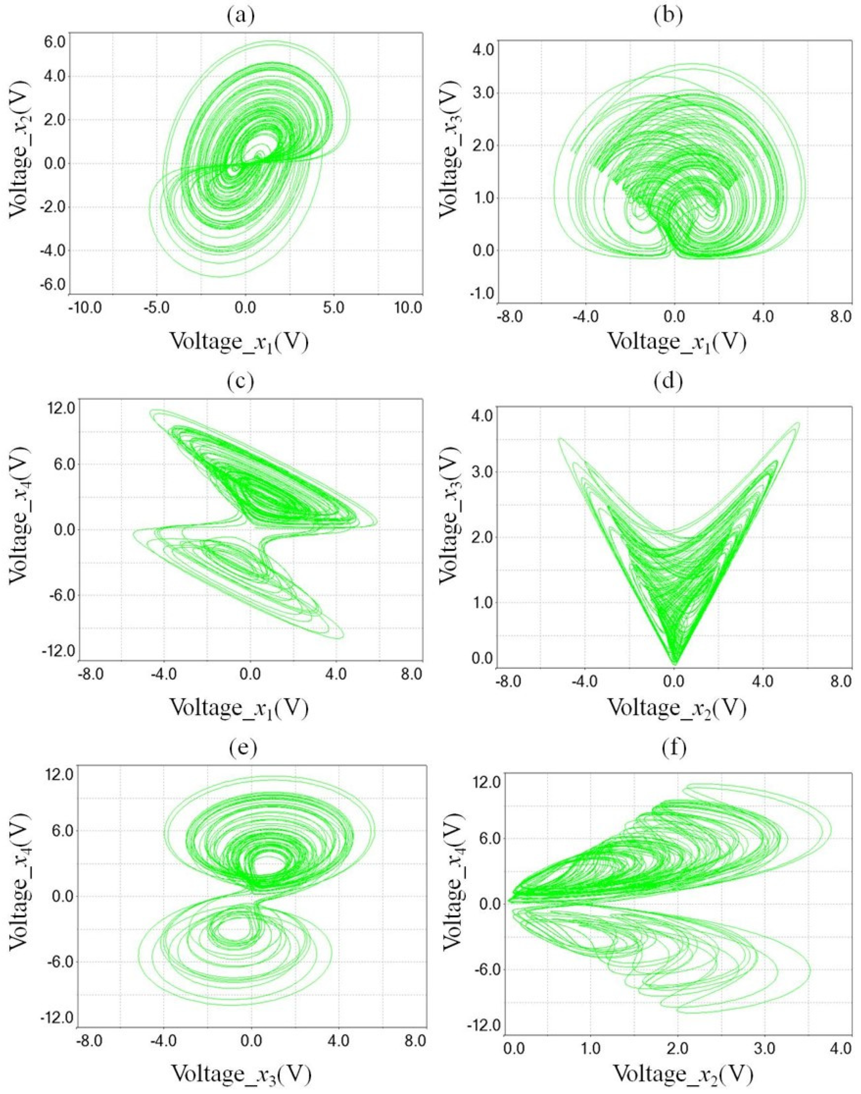
The components of the chaotic circuit are chosen to be: R1 = R3 = R4 = R5 = R8 = R9 = R10 = R11 = R12 = R13 = R14 = R15 = 100 k, R2 = 204 k, R6 = 267 k, R7 = 330 k and C1 = C2 = C3 = C4 = 0.471 uF. The voltage output signals of the chaotic circuit simulated in Multisim are shown in Figure 4, which can be compared with the phase portraits simulated via MATLAB in Figure 2. It is clear that the chaotic behaviors revealed in MATLAB and Multisim are very close.
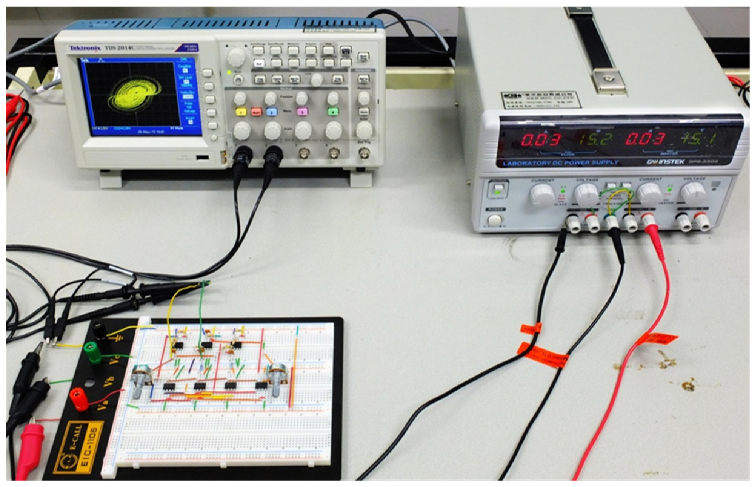
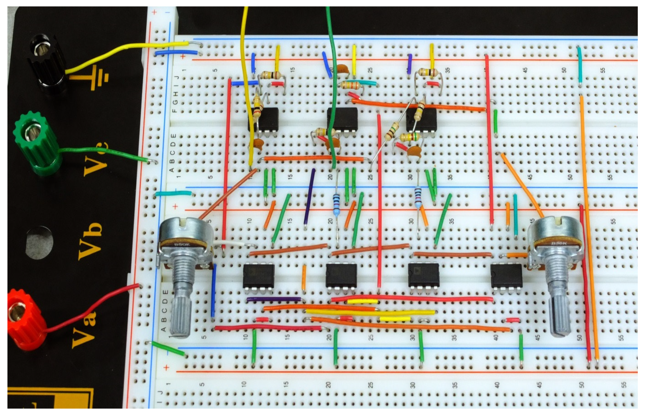
In the second-stage hardware implementation, the real circuit of the four-dimensional Chen–Lee system is going to be constructed on a breadboard; the main electrical components comprise a DC power supply, oscilloscope, OP-amplifier, multiplier, capacitor, etc. The apparatus and the components used in the circuit are listed in Table 1.
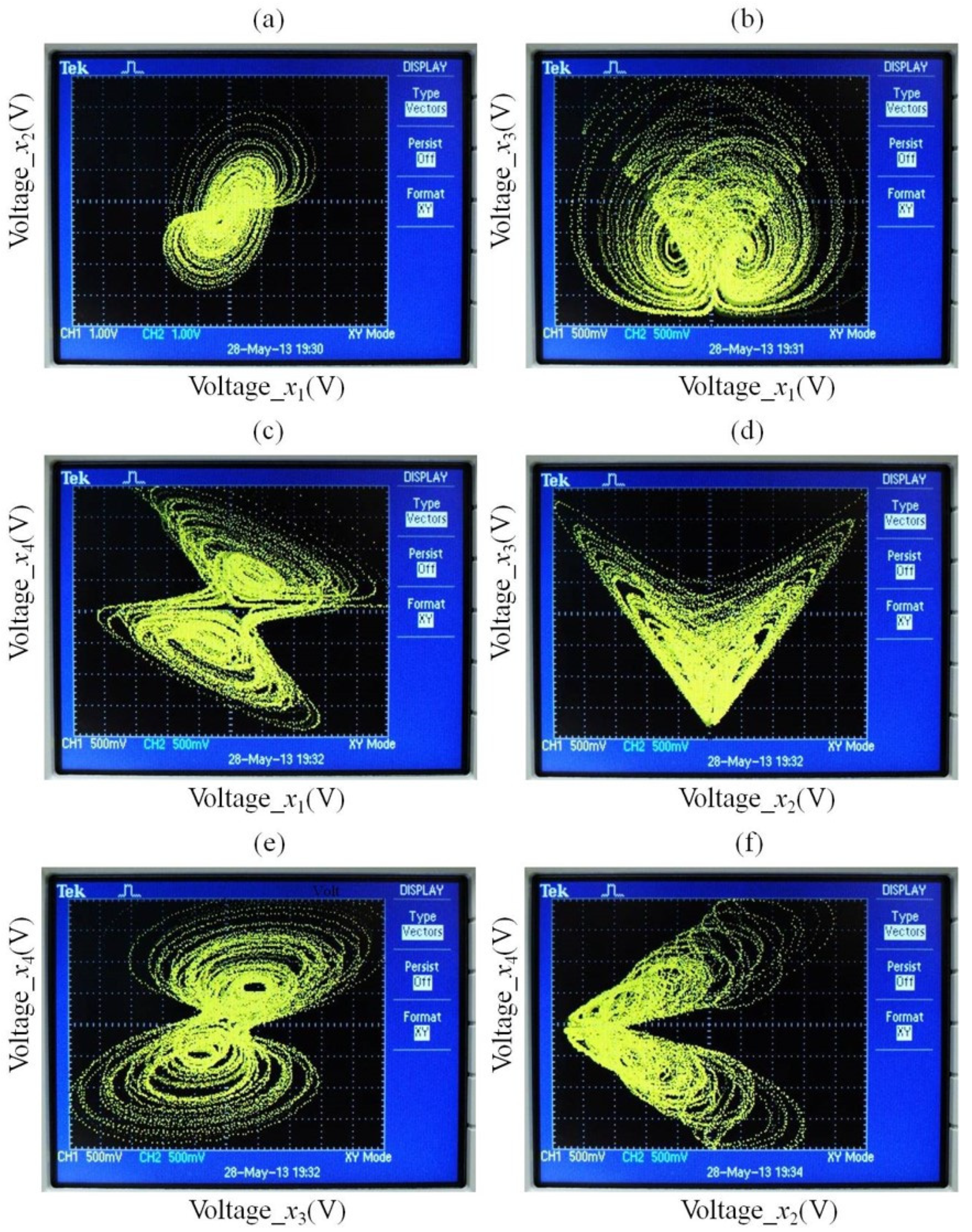
In addition, the complete experimental setup is clearly shown in Figure 5 and the whole hardware configurations are also given in Figure 6; the experimental results are shown in Figure 7. Obviously, in comparison with the experiment results and the simulation results provided via MATLAB and Multisim, the chaotic behaviors shown in our experiment are extremely close to the original chaotic solutions solved by MATLAB; i.e., the chaotic signal generated from our electronic circuits retain original information and can be used to further applications in our daily life, such as secure communication, data encryption, medical information protection, etc.
4. Adaptive Synchronization of the Four-Dimensional Chen–Lee System on Electronic Circuits
In this section, we further accomplish the adaptive synchronization of the four-dimensional Chen–Lee system through electronic circuits implementation. In the first step, we choose the circuit Equation (4) as the master Chen–Lee system with four states:
where x1, x2, x3, and x4 are system states, a = 5, b = 0.9, c = −10, d = −3.8, and r = −2. The initial conditions are: x1(0) = 1.2 V, x2 (0) = 1.2 V, x3(0) = 1.2 V, and x4(0) = 1.2 V.
The slave four-dimensional Chen–Lee system is:
where x1, x2, x3, and x4 are system states, and the initial conditions are: x1(0) = −1 V, x2(0) = −1 V, x3(0) = −1 V, and x4(0) = −1 V. In order to lead y1, y2, y3, and y4, into x1, x2, x3, and x4, we add nonlinear controllers, u1, u2, u3, and u4, to each equation in Equation (5), respectively. Then we have:
where , and are estimates of uncertain parameters a, b, c, d, and r, respectively. These controllers make the two systems achieve synchronization when , and the limit of the error function approaches zero, where the error function can be defined as: ei = xi-yi, (i = 1,2,3,4). From the error function, we obtain the error dynamics:
where , and . We choose a Lyapunov function in the form of a positive definite function:
and its time derivative is:
We choose the update law for uncertain parameters as:
The initial values of estimates for uncertain parameters are and . Through Equation (9) and Equation (10), the appropriate controllers can be designed as:
where k is a positive constant and we choose k = 3.12.
Substituting Equations (10) and (11) into Equation (9), we obtain:
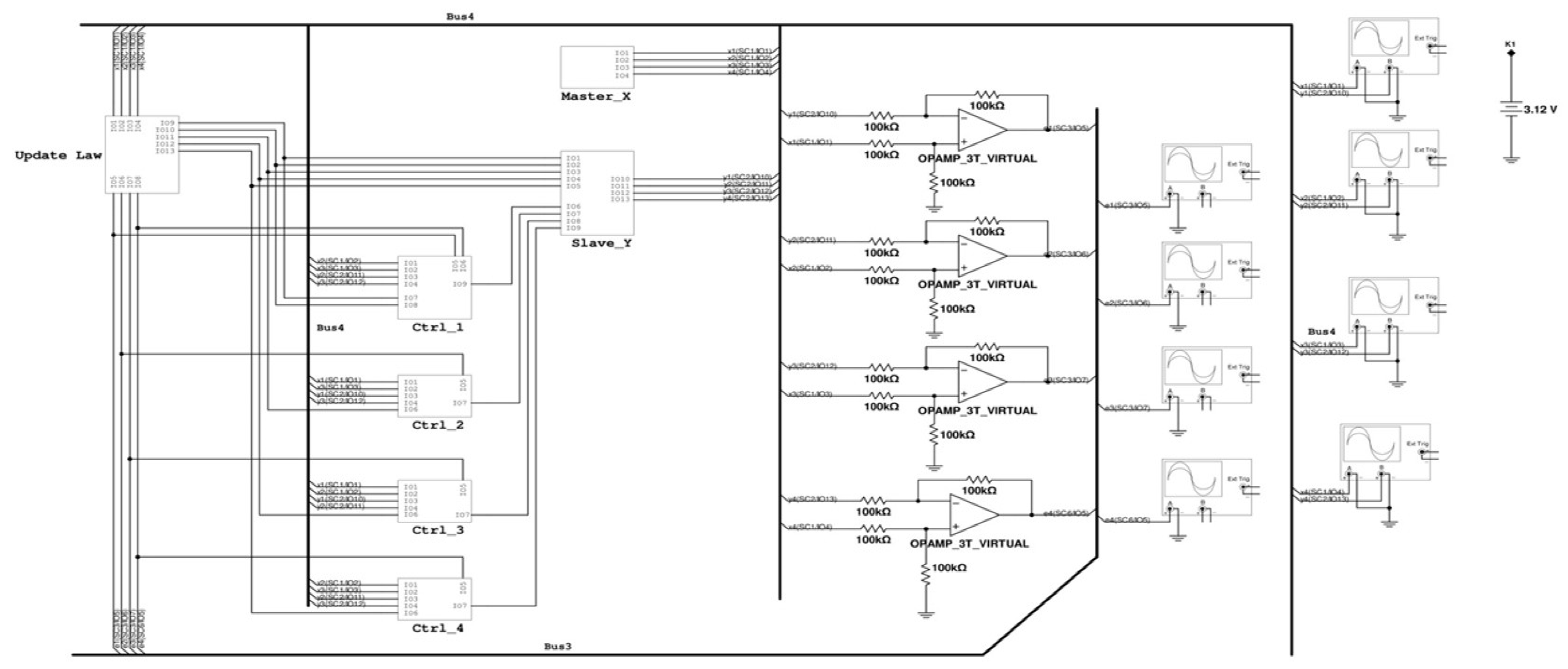
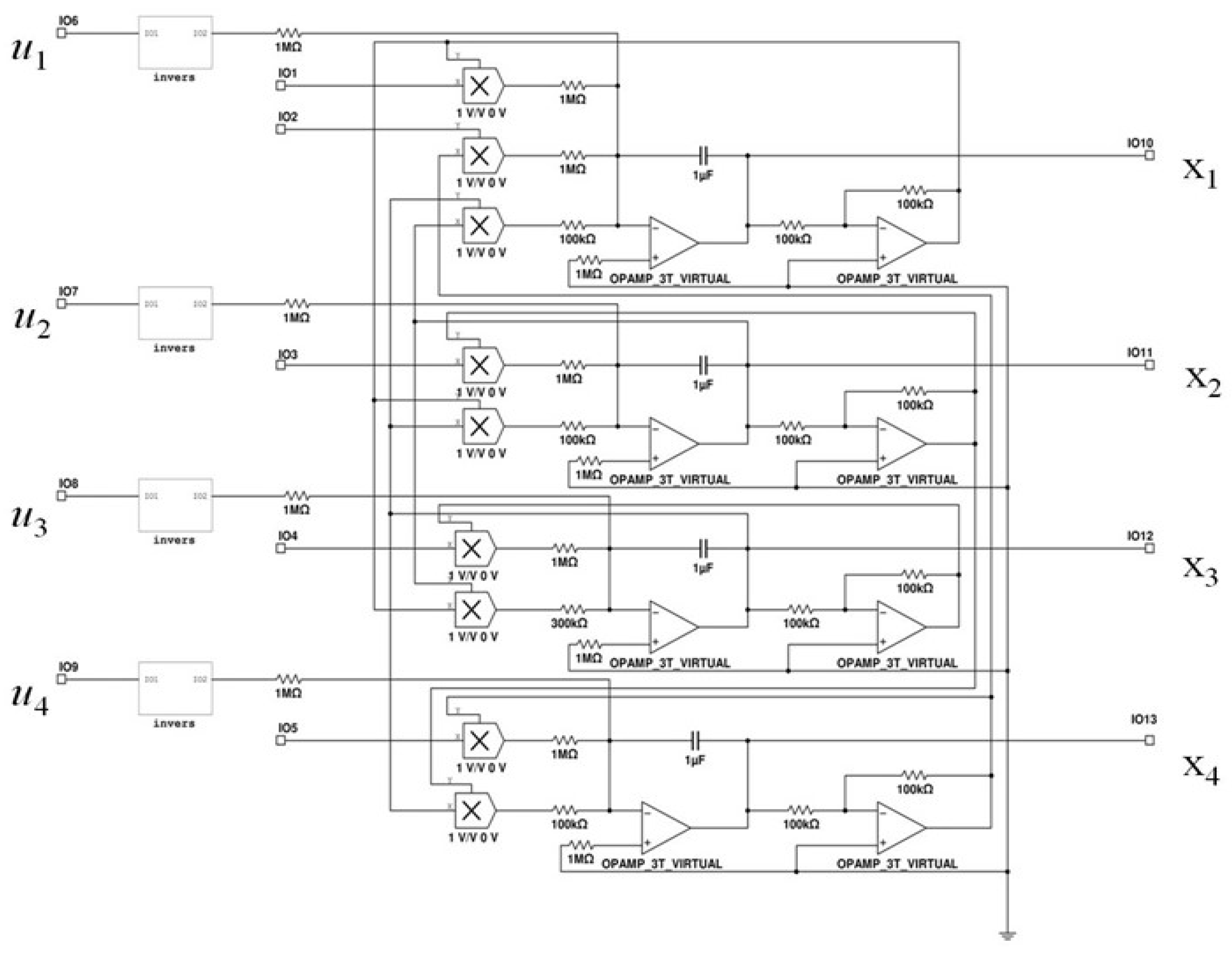
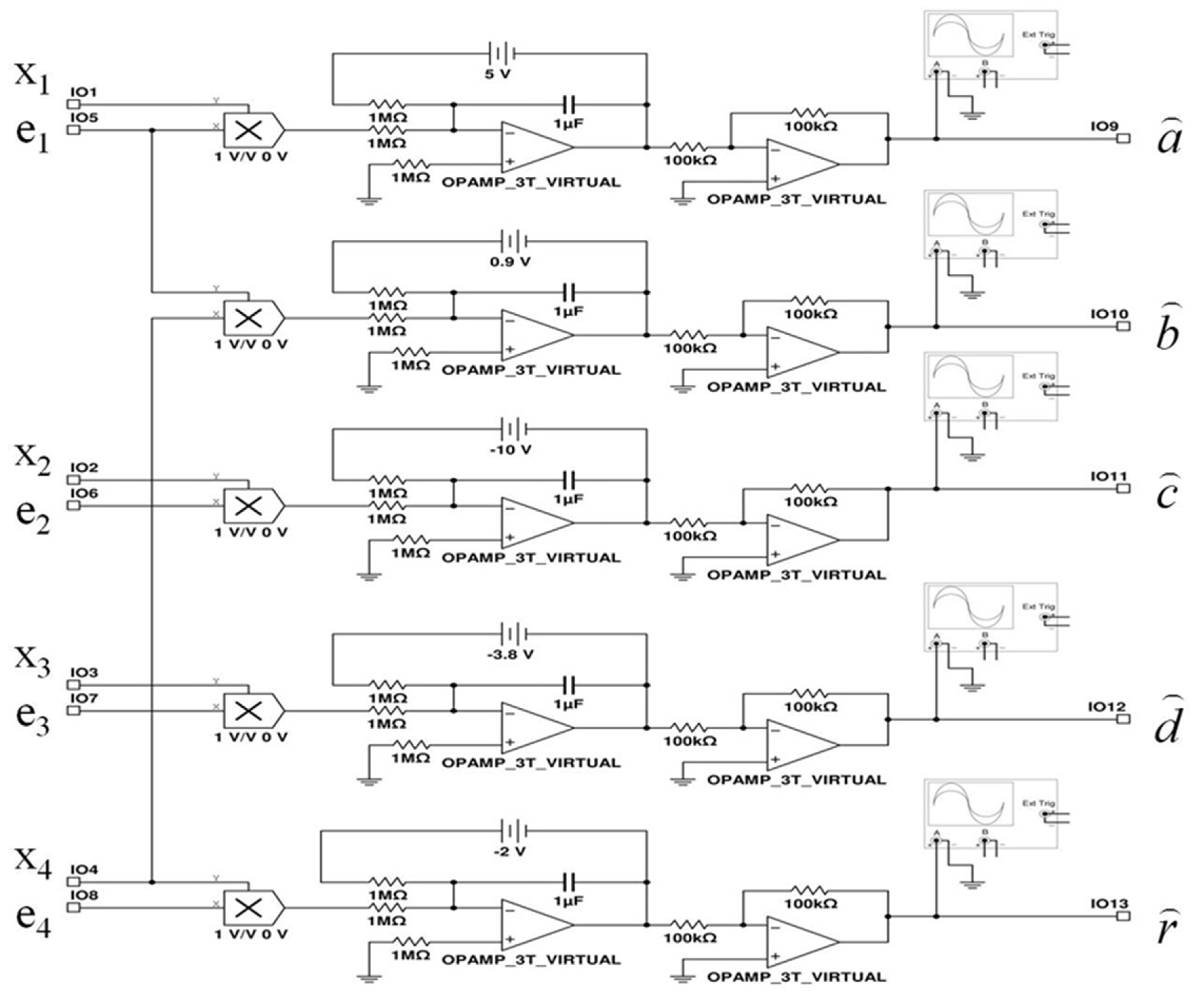
which is a negative-definite function of . Following up the designing logic of electronic circuits mentioned in those previous sections, the complete configuration of the adaptive circuit is presented in Figure 8, where the detailed circuit configuration of the master system and slave system are given in Figure 9 and Figure 10, and the corresponding parameters update law is clearly provided in Figure 11.
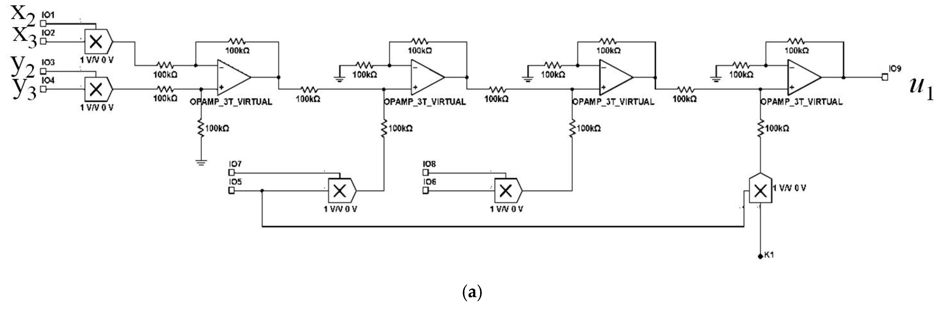
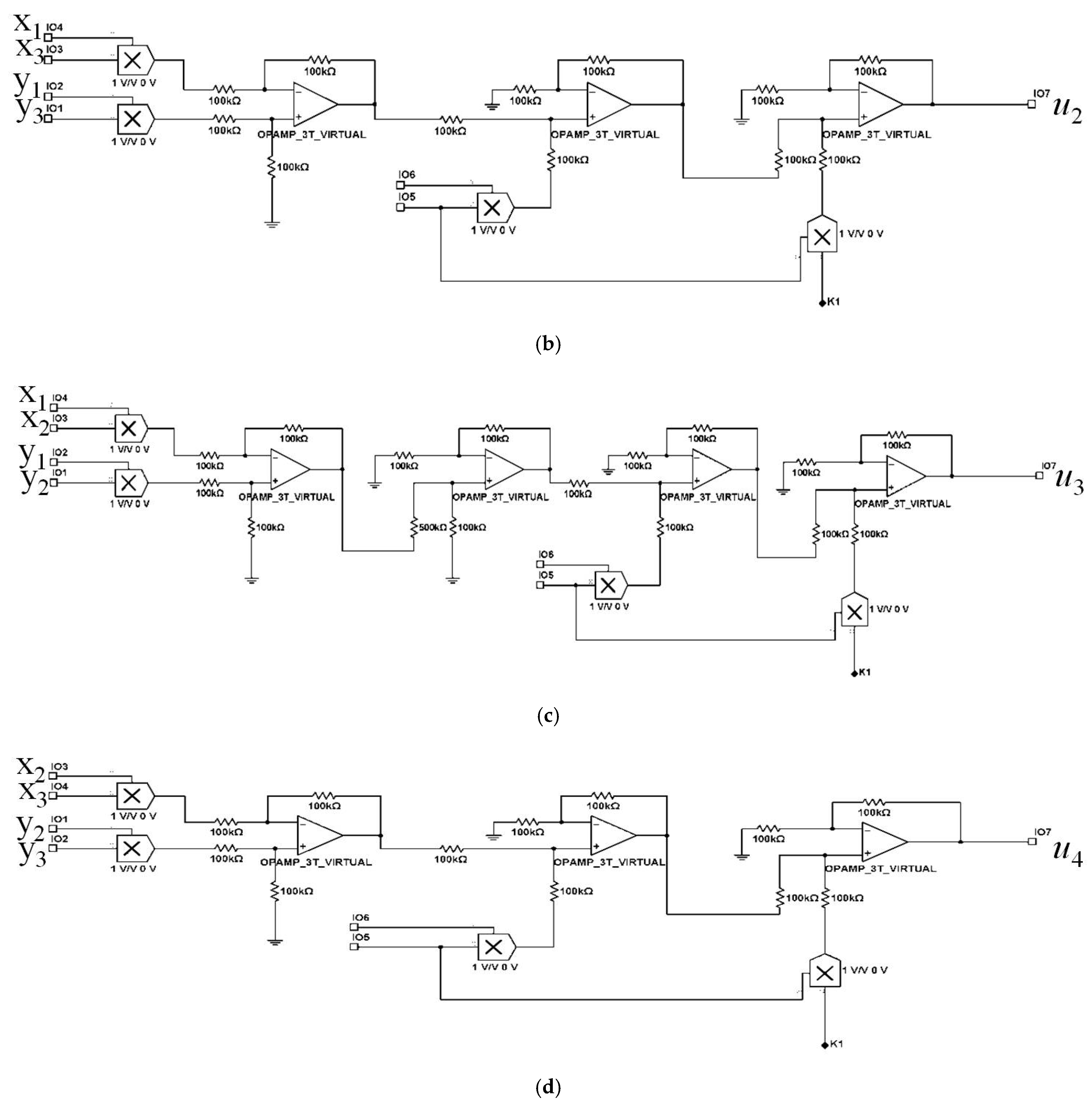
Furthermore, according to the designed controllers u1, u2, u3, and u4 derived in Equation (11), the circuit configuration of the proposed controllers u1, u2, u3, and u4 are further listed below in Figure 12, where:
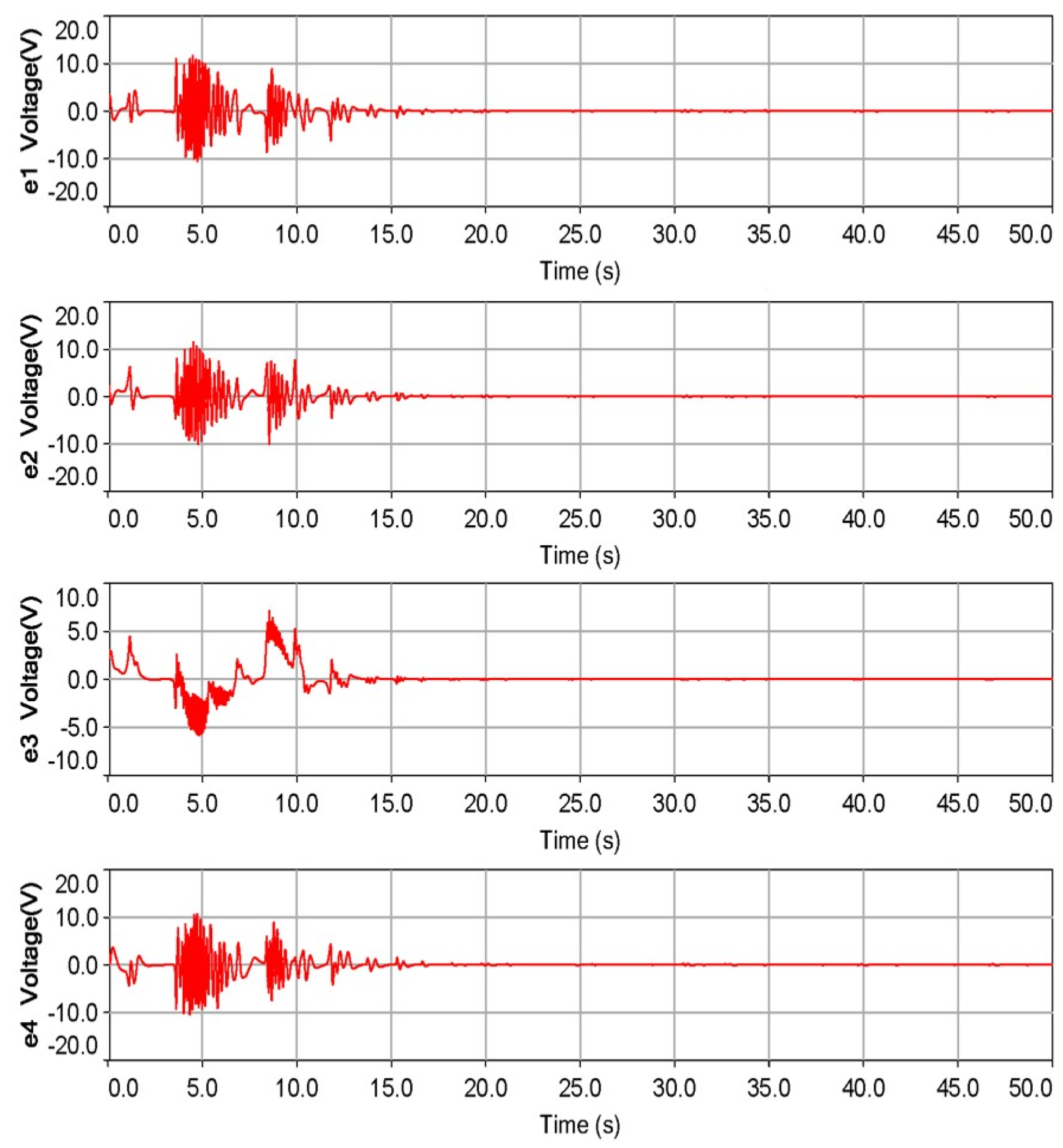
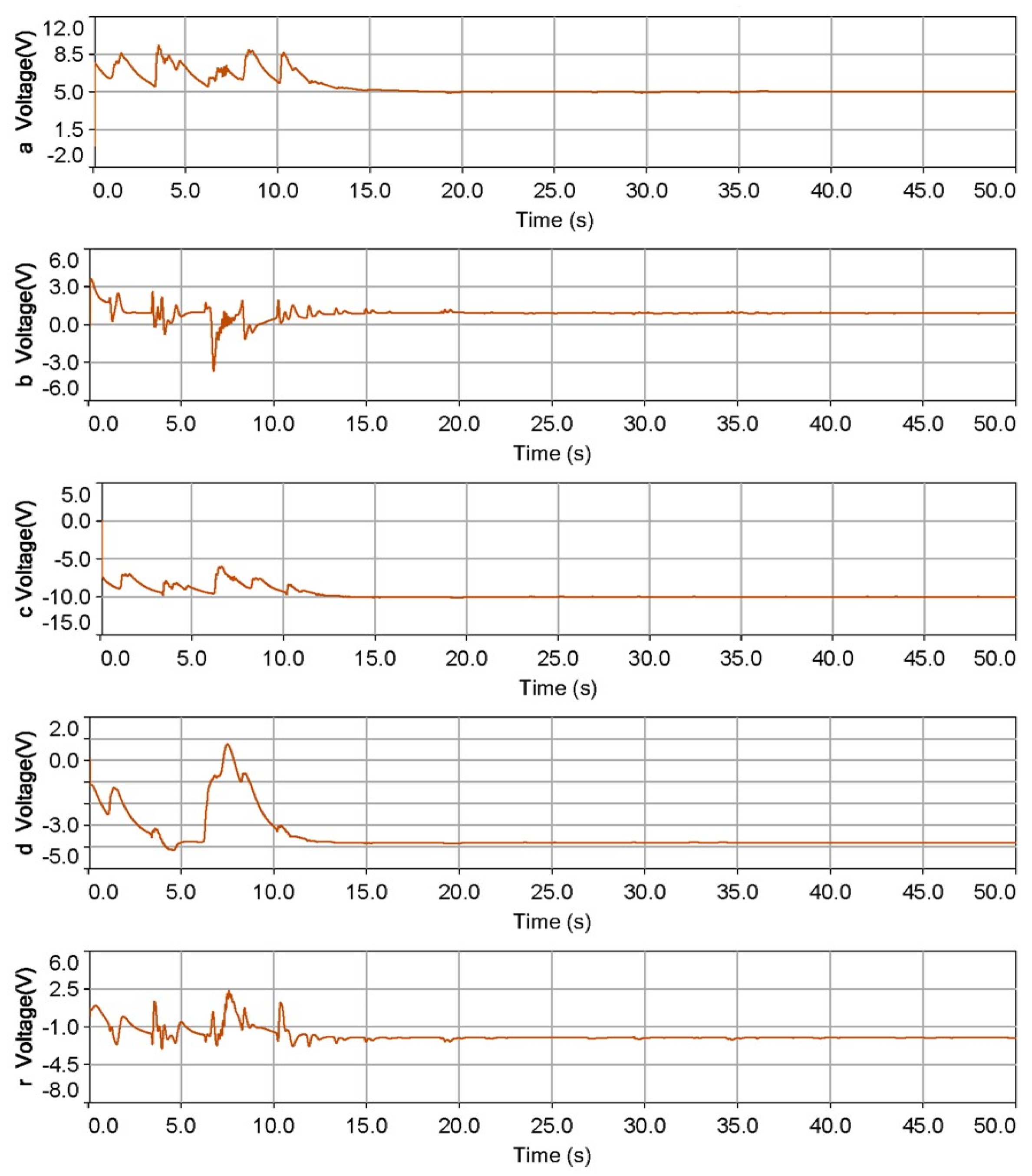
The results of the adaptive synchronization of the two four-order Chen–Lee systems are provided in Figure 13 and Figure 14, where the error states are approaching the original points within 15–20 sec shown in Figure 13 and the estimated parameters are going to achieve the goal value within 15 s given in Figure 14. Consequently, the slave four-dimensional Chen–Lee system has been successfully adaptive control to the master system with both errors states and estimated parameters following our adaptive control law and hardware design on the real electronic circuits.
5. Conclusions
In this paper, we generated chaotic signals and made comparisons between the m step by step through the following three different approaches on two aspects—(1) software: numerical simulation via MATLAB and implementation on electronic circuit software through Multisim; (2) hardware: realization on breadboard with a DC power supply, oscilloscope, OP-amplifier, multiplier, and capacitor. We provided a set of complete and hieratical investigating flowcharts of the realization process; the simulation and experimental results showed that the proposed process is effective. Furthermore, following the same realization rules, the adaptive chaotic signal was also designed and presented in the end of this article for further study. All those experimental results show that our design is mature and can be applied to technical transferring of real encryption application in the next research step. Moreover, the signals generated by chaotic circuits proposed in this article can be applied to various kinds of secure applications, such as image and text encryption, secure communication, data hiding, and so forth; as a result, the real applications in the cryptography field will be considered and implemented in the near future.
Author Contributions
Conceptualization, S.-Y.L.; Data curation, C.-L.C.; Formal analysis, C.-H.Y. and C.-L.C.; Investigation, C.-H.Y., C.-L.C. and S.-Y.L.; Methodology, C.-H.Y.; Resources, C.-H.Y.; Software, C.-L.C. and S.-Y.L.; Supervision, C.-H.Y. and S.-Y.L.; Validation, C.-L.C.; Visualization, S.-Y.L.; Writing—original draft, C.-H.Y. and C.-L.C.; Writing—review & editing, S.-Y.L. All authors have read and agreed to the published version of the manuscript.
Funding
This study was funded by the Ministry of Science and Technology (MOST107-2628-E-027-003-MY3) and (MOST 110-2221-E-027-080).
Institutional Review Board Statement
Not applicable.
Informed Consent Statement
Not applicable.
Data Availability Statement
Not applicable.
Conflicts of Interest
The authors declare no conflict of interest. The funders had no role in the design of the study; in the collection, analyses, or interpretation of data; in the writing of the manuscript, or in the decision to publish the results.
References
- Cena, G.; Bertolotti, I.C.; Scanzio, S.; Valenzano, A.; Zunino, C. Synchronize Your Watches: Part II: Special-Purpose Solutions for Distributed Real-Time Control. IEEE Ind. Electron. Mag. 2013, 7, 27–39. [Google Scholar] [CrossRef]
- Li, R. A note on decay of correlation implies chaos in the sense of Devaney. Appl. Math. Model. 2015, 39, 6705–6710. [Google Scholar] [CrossRef]
- Pan, I.; Das, S.; Routh, A. Towards a global controller design for guaranteed synchronization of switched chaotic systems. Appl. Math. Model. 2015, 39, 2311–2331. [Google Scholar] [CrossRef]
- Tam, L.-M.; Lao, S.-K.; Sheu, L.-J.; Chen, H.-K. Impulsive Synchronization and Its Implementation in Chen–Lee Systems. Int. J. Mod. Phys. B 2011, 25, 3893–3903. [Google Scholar] [CrossRef]
- Li, H.; Wang, J.; Shi, P. Output-Feedback Based Sliding Mode Control for Fuzzy Systems with Actuator Saturation. IEEE Trans. Fuzzy Syst. 2016, 24, 1282–1293. [Google Scholar] [CrossRef]
- Li, S.Y.; Tam, L.M.; Tsai, S.E.; Ge, Z.M. Novel Fuzzy Modeling and Synchronization of Chaotic Systems with Multinon-linear Terms by Advanced Ge-Li Fuzzy Model. IEEE Trans. Cybern. Seb. 2015, 46, 2228–2237. [Google Scholar] [CrossRef]
- Trcala, M. Spectral stochastic modeling of uncertainties in nonlinear diffusion problems of moisture transfer in wood. Appl. Math. Model. 2015, 39, 1740–1748. [Google Scholar] [CrossRef]
- Wang, X.; Chen, Y.; Han, G.; Song, C. Nonlinear dynamic analysis of a single-machine infinite-bus power system. Appl. Math. Model. 2015, 39, 2951–2961. [Google Scholar] [CrossRef]
- Li, H.; Chen, Z.; Wu, L.; Lam, H.-K.; Du, H. Event-Triggered Fault Detection of Nonlinear Networked Systems. IEEE Trans. Cybern. 2016, 47, 1041–1052. [Google Scholar] [CrossRef] [Green Version]
- Gholipour, R.; Khosravi, A.; Mojallali, H. Multi-objective optimal backstepping controller design for chaos control in a rod-type plasma torch system using Bees algorithm. Appl. Math. Model. 2015, 39, 4432–4444. [Google Scholar] [CrossRef]
- Pan, I.; Das, S.; Das, S. Multi-objective active control policy design for commensurate and incommensurate fractional or-der chaotic financial systems. Appl. Math. Model. 2015, 39, 500–514. [Google Scholar] [CrossRef]
- Liang, S.; Wu, R.; Chen, L. Comparison principles and stability of nonlinear fractional-order cellular neural networks with multiple time delays. Neurocomputing 2015, 168, 618–625. [Google Scholar] [CrossRef]
- Nana, B.; Woafo, P. Chaotic masking of communication in an emitter–relay–receiver electronic setup. Nonlinear Dyn. 2015, 82, 899–908. [Google Scholar] [CrossRef]
- Abedini, M.; Gomroki, M.; Salarieh, H.; Meghdari, A. Identification of 4D Lü hyper-chaotic system using identical sys-tems synchronization and fractional adaptation law. Appl. Math. Modell. 2014, 38, 4652–4661. [Google Scholar] [CrossRef]
- Lin, C.-J.; Su, X.-Y.; Yu, K.-T.; Jian, B.-L.; Yau, H.-T. Inspection on Ball Bearing Malfunction by Chen-Lee Chaos System. IEEE Access 2020, 8, 28267–28275. [Google Scholar] [CrossRef]
- Li, S.-Y.; Gu, K.-R. A smart fault-detection approach with feature production and extraction processes. Inf. Sci. 2020, 513, 553–564. [Google Scholar] [CrossRef]
- Li, S.-Y.; Gu, K.-R.; Huang, S.-C. A chaotic system-based signal identification Technology: Fault-diagnosis of industrial bearing system. Measurement 2021, 171, 108832. [Google Scholar] [CrossRef]
- Anees, A.; Siddiqui, A.M.; Ahmed, F. Chaotic substitution for highly autocorrelated data in encryption algorithm. Commun. Nonlinear Sci. Numer. Simul. 2014, 19, 3106–3118. [Google Scholar] [CrossRef]
- Sadeghian, H.; Salarieh, H.; Alasty, A.; Meghdari, A. On the fractional-order extended Kalman filter and its application to chaotic cryptography in noisy environment. Appl. Math. Model. 2014, 38, 961–973. [Google Scholar] [CrossRef]
- Li, S.Y.; Hernández, M.A.B.; Tam, L.M.; Chen, C.S. A Cloud Image Data Protection Algorithm with Multi-Level Encryption Scheme and Automated-Selection Mechanism. Appl. Sci. 2019, 9, 5146. [Google Scholar] [CrossRef] [Green Version]
- Schimmack, M.; Costa, M.L.; Mercorelli, P. Comparing Two Voltage Observers in a Sensorsystem using Repetitive Control. IFAC-PapersOnLine 2016, 49, 7–11. [Google Scholar] [CrossRef]
- Su, Y.; Zheng, C.; Mercorelli, P. Global Finite-Time Stabilization of Planar Linear Systems with Actuator Saturation. IEEE Trans. Circuits Syst. II Express Briefs 2016, 64, 947–951. [Google Scholar] [CrossRef]
- Braune, S.; Liu, S.; Mercorelli, P. Design and control of an electromagnetic valve actuator. In Proceedings of the 2006 IEEE Conference on Computer Aided Control System Design, 2006 IEEE International Conference on Control Applications, 2006 IEEE International Symposium on Intelligent Control, Munich, Germany, 4–6 October 2006; pp. 1657–1662. [Google Scholar]
- Mercorelli, P.; Werner, N. An Adaptive Resonance Regulator Design for Motion Control of Intake Valves in Camless Engine Systems. IEEE Trans. Ind. Electron. 2016, 64, 3413–3422. [Google Scholar] [CrossRef]
- Murali, K.; Yu, H.; Varadan, V.; Leung, H. Secure communication using a chaos based signal encryption scheme. IEEE Trans. Consum. Electron. 2001, 47, 709–714. [Google Scholar] [CrossRef]
- Nguyen, N.; Pham-Nguyen, L.; Nguyen, M.B.; Kaddoum, G. A Low Power Circuit Design for Chaos-Key Based Data En-cryption. IEEE Access 2020, 8, 104432–104444. [Google Scholar] [CrossRef]
- Chen, J.-J.; Yan, D.-W.; Duan, S.-K.; Wang, L.-D. Memristor-based hyper-chaotic circuit for image encryption. Chin. Phys. B 2020, 29, 110504. [Google Scholar] [CrossRef]
- Mohamed, G.; Nessrine, A.; Mohamed, A.H.; Jihene, M.; Abdellatif, M. Improved Chaos-Based Cryptosystem for Medical Image Encryption and Decryption. Scient. Program. 2020, 2020, 1–22. [Google Scholar]
- Baby, H.T.; Sujatha, B.R. Voice and Text Encryption using Chaotic Circuits. Int. J. Innovat. Tech. Explor. Eng. 2020, 9, 1181–1184. [Google Scholar]
- Chen, H.-K.; Lee, C.-I. Anti-control of chaos in rigid body motion. Chaos Solitons Fractals 2004, 21, 957–965. [Google Scholar] [CrossRef]
Figure 1.
A comprehensive reveal: 3-D phase portrait and its 3-axis projections of the four-dimensional Chen–Lee system.
Figure 1.
A comprehensive reveal: 3-D phase portrait and its 3-axis projections of the four-dimensional Chen–Lee system.

Figure 2.
This 2-D phase portraits of the four-dimensional Chen–Lee system simulated by MATLAB: (a) plane; (b) plane; (c) plane; (d) plane; (e) plane; (f) plane.
Figure 2.
This 2-D phase portraits of the four-dimensional Chen–Lee system simulated by MATLAB: (a) plane; (b) plane; (c) plane; (d) plane; (e) plane; (f) plane.

Figure 3.
Circuit configuration of the four-dimensional Chen–Lee system designed on Multisim.

Figure 4.
2-D phase portraits of the four-dimensional Chen–Lee system simulated by electronic circuits software Multisim: (a) plane; (b) plane; (c) plane; (d) plane; (e) plane; (f) plane.
Figure 4.
2-D phase portraits of the four-dimensional Chen–Lee system simulated by electronic circuits software Multisim: (a) plane; (b) plane; (c) plane; (d) plane; (e) plane; (f) plane.

Figure 5.
Experimental setup for realization of the four-dimensional Chen–Lee system.

Figure 6.
Hardware configurations: real circuit of the four-order Chen–Lee system.

Figure 7.
2-D phase portraits of the four-dimensional Chen–Lee system implemented on real electronic circuits: (a) plane; (b) plane; (c) plane; (d) plane; (e) plane; (f) plane.
Figure 7.
2-D phase portraits of the four-dimensional Chen–Lee system implemented on real electronic circuits: (a) plane; (b) plane; (c) plane; (d) plane; (e) plane; (f) plane.

Figure 8.
Circuit configuration of the whole adaptive electronic circuits.

Figure 9.
Circuit configuration of the master system.

Figure 10.
Circuit configuration of the slave system.

Figure 11.
Circuit configuration of the parameters update law.

Figure 12.
Circuit configuration of the controllers u1, u2, u3, and u4: (a) controller u1; (b) controller u2; (c) controller u3; (d) controller u4.
Figure 12.
Circuit configuration of the controllers u1, u2, u3, and u4: (a) controller u1; (b) controller u2; (c) controller u3; (d) controller u4.


Figure 13.
Time histories of the error states.

Figure 14.
Time histories of the estimated parameters.


Table 1.
List of apparatus and components in the circuit experiment.
| Apparatus/Components | Model | Quantity |
|---|---|---|
| DC Power Supply | GPS-3303 | 1 |
| Oscilloscope | TDS2014C | 1 |
| OP-Amplifier | LF412CN | 4 |
| Multiplier | AD633 | 4 |
| Capacitor | 417 uF | 4 |
| Resister | 100 KΩ 204 KΩ 267 KΩ Variable resistor 50 K Ω | 11 1 1 2 |
Publisher’s Note: MDPI stays neutral with regard to jurisdictional claims in published maps and institutional affiliations. |
© 2021 by the authors. Licensee MDPI, Basel, Switzerland. This article is an open access article distributed under the terms and conditions of the Creative Commons Attribution (CC BY) license (https://creativecommons.org/licenses/by/4.0/).
Share and Cite
MDPI and ACS Style
Yang, C.-H.; Chang, C.-L.; Li, S.-Y. Adaptive Control of Chaotic Signals: Investigated by Simulation Software and Real Electronic Circuits. Actuators 2021, 10, 284. https://doi.org/10.3390/act10110284
AMA Style
Yang C-H, Chang C-L, Li S-Y. Adaptive Control of Chaotic Signals: Investigated by Simulation Software and Real Electronic Circuits. Actuators. 2021; 10(11):284. https://doi.org/10.3390/act10110284
Chicago/Turabian StyleYang, Cheng-Hsiung, Che-Lun Chang, and Shih-Yu Li. 2021. "Adaptive Control of Chaotic Signals: Investigated by Simulation Software and Real Electronic Circuits" Actuators 10, no. 11: 284. https://doi.org/10.3390/act10110284
Note that from the first issue of 2016, this journal uses article numbers instead of page numbers. See further details here.