Article

Development of Wearable Finger Prosthesis with Pneumatic Actuator for Patients with Partial Amputations

1
Department of Mechanical Engineering, Incheon National University, 119, Academy-ro, Yeonsu-gu, Incheon 22012, Republic of Korea
2
Material & Component Convergence R&D Department, Research Institute of Convergence Technology, Korea Institute of Industrial Technology, 143, Hanggaul-ro, Sangnok-gu, Ansan-si 15588, Republic of Korea
*
Authors to whom correspondence should be addressed.
These authors contributed equally to this work.
Actuators 2023, 12(12), 434; https://doi.org/10.3390/act12120434
Submission received: 25 September 2023 / Revised: 19 November 2023 / Accepted: 20 November 2023 / Published: 23 November 2023
(This article belongs to the Section Actuators for Robotics)

Abstract

:
As the number of patients with amputations increases, research on assistive devices such as prosthetic limbs is actively being conducted. However, the development of assistive devices for patients with partial amputations is insufficient. In this study, we developed a finger prosthesis for patients with partial amputations. The design and mathematical modeling of the prosthesis are briefly presented. A pneumatic actuator, based on the McKibben muscle design, was employed to drive the finger prosthesis. We characterized the relationship between the actuator’s force and axial length changes with varying pressure. An empirical model derived from conventional mathematical modeling of force and axis length changes was proposed and compared with experimental data, and the error was measured to be between about 3% and 13%. In order to control the actuator using an electromyography (EMG) signal, an electrode was attached to the user’s finger flexors. The EMG signal was measured in relation to the actual gripping force and was provided with visual feedback, and the magnitude of the signal was evaluated using root mean square (RMS). Depending on the evaluated EMG signal magnitude, the pressure of the actuator was continuously adjusted. The pneumatic pressure was adjusted between 100 kPa and 250 kPa, and the gripping force of the finger prosthesis ranged from about 0.7 N to 6.5 N. The stiffness of the prosthesis can be varied using the SMA spring. The SMA spring is switched to a fully austenite state at 50 °C through PID control, and when the finger prosthesis is bent to a 90° angle, it can provide approximately 1.2 N of assistance force. Finally, the functional evaluation of the finger prosthesis was performed through a pinch grip test of eight movements.

1. Introduction

Upper limb amputations can result from various causes, including traffic accidents, industrial accidents, and diseases like diabetes. In the United States, each year witnesses 50,000 to 100,000 new amputation cases. Of these, more than 80% are upper limb amputations, and over 70% of these specifically involve the wrist, hand, or fingers [1]. As the cumulative number of patients continues to grow, so does the demand for prostheses. The development of prosthetic limbs offers these individuals an opportunity to reintegrate into society, and prosthetic limbs not only enhance the quality of life for patients but also create a positive ripple effect by reducing social welfare costs and boosting productivity.
Most commercially available prostheses today prioritize aesthetic design over functional utility, using silicone to emulate skin texture. With recent technological advancements, research is now focusing on prostheses that incorporate numerous sensors and actuators capable of mimicking the movements of a natural human hand. However, many patients are deterred from opting for powered prostheses due to challenges like excessive weight, high costs, insufficient grip strength, and subpar control performance. Moreover, there is a noticeable gap in the development of powered prostheses specifically designed for patients with partial finger amputations. Thus, it is necessary to develop a finger prosthesis to resolve these shortcomings. Previously developed prosthetic and robotic hands can be seen in Table 1. Mural et al. [2] proposed a self-powered auxiliary finger, featuring an embedded compact motor adaptable to various sizes. It was manufactured using direct laser metal sintering to create its gear transmission; however, this device cannot adjust the gripping force based on the user’s intent and presents structural complexity issues. Ryu et al. [3] proposed a lightweight glove-type assistive device designed for patients retaining a thumb and some metacarpals. This device can also operate passively, utilizing linear and torsion springs. By positioning an actuator vertically between the finger module and its attachment, the authors addressed the installation space constraints of existing devices. However, customizing this assistive device for individual patients remains challenging.
While most finger prostheses can mimic finger-like motions, they often fall short in enhancing grip strength or adapting stiffness. Moreover, the diversity in residual limb structures, stemming from various amputation types, makes it challenging to devise a universal solution for all amputees. As a result, research is gravitating towards wearable exoskeleton devices designed to augment grip strength and facilitate movement. Gonzalez et al. [4] developed a rehabilitation exoskeleton robotic hand capable of complete movements across all finger joints, both manually and automatically, and Burns et al. [5] introduced a glove-type, tendon-driven exoskeleton that can flex and extend each finger using two motors. However, the structural complexity of these wearable exoskeletons poses challenges for partial amputees. Ceccarelli et al. [6] developed a finger exoskeleton with a unique design, offering a full range of finger movements, and Li et al. [7] introduced an under-actuated finger exoskeleton operating with a single motor; this design pre-couples the movements of the MCP, PIP, and DIP joints to achieve pre-shaping. However, many of these exoskeletons have a bulky design, causing inconveniences and limitations during daily activities. Wang et al. [8] introduced a single-finger exoskeleton driven by shape-memory alloy wires; however, this exoskeleton’s maximum flexion angles for each joint are significantly smaller than the natural maximum flexion angles of the human PIP and DIP joints, leading to considerable movement restrictions. Since finger flexion is integral to grip strength, these limitations reduce the effective control of grip strength.
In response, we developed a wearable finger prosthesis for patients with partial finger amputations as shown in Figure 1. Our design introduces a mechanism for continuous grip strength control using an EMG sensor, with the system comprising a main body, a pneumatic actuator, and the EMG sensor, while the finger prosthesis’s main body connects to the pneumatic actuator via a cable. The pneumatic actuator functions based on the myoelectric signals detected by the EMG sensor, facilitating continuous grip strength control. Additionally, in scenarios where a load is applied to the finger, the system ensures that the finger retains a flexed position for a specified duration. Considering the difficulty for users in sustaining high-level myoelectric signals, we employed and evaluated a variable stiffness mechanism [9,10,11] using shape-memory alloys (SMAs) for wearable finger prostheses. While many mechanisms have been proposed for variable stiffness [12,13,14,15,16], we chose SMAs. These materials can be used for an extended period of time [17] due to their ability to return to their original state without undergoing permanent deformation when exposed to specific stimuli such as heat [18] or magnetic fields, provided that the deformation remains below a certain threshold. Their selection was motivated by their aptness for lightweight and miniaturized applications, coupled with their exceptional force-to-weight characteristics [19].
Section 2 focuses on the design of the wearable finger prosthesis for patients with partial amputations and provides a brief overview of the associated mathematical modeling. We also developed a pneumatic actuator based on the McKibben muscle design [20,21] for the proposed finger prosthesis. Section 3 delves into controlling the actuator by analyzing the magnitude of myoelectric signals from the EMG sensor, adjusting the grip strength of the finger prosthesis accordingly. For example, objects with the same volume but varying weights necessitate different grip strengths, underscoring the importance of grip control via the EMG sensor. Section 4 integrates the developed finger prosthesis with the EMG-controlled grip mechanism. We also tested the prosthesis’s variable stiffness method using SMA springs. A functional evaluation of the finger prosthesis using pinch grip motions will also be reported. Lastly, Section 5 presents our conclusions and outlines potential directions for future research.

2. Design of Wearable Finger Prosthesis

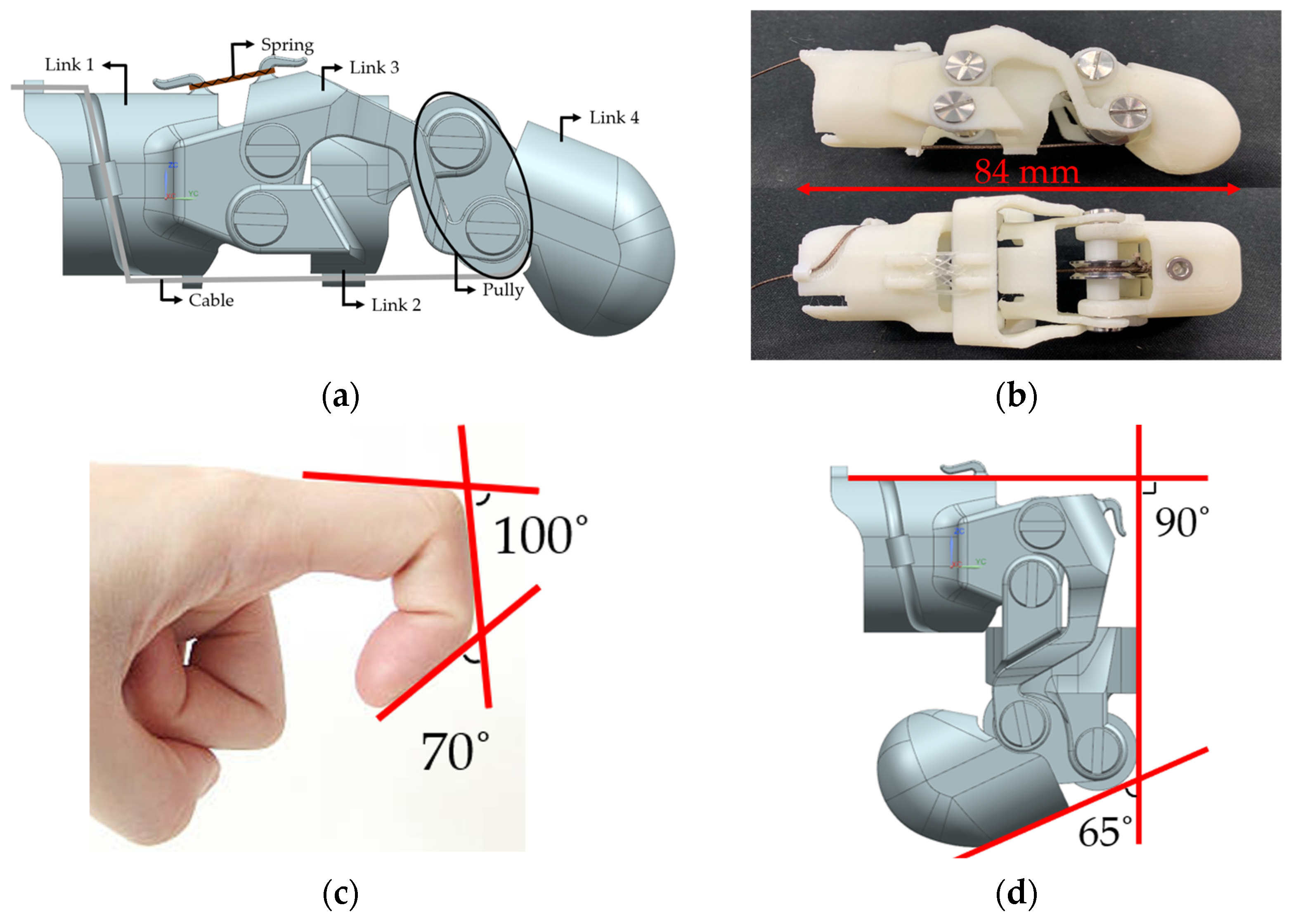
2.1. Structural Design

The finger prosthesis that we aimed to develop has been designed structurally through NX12 (Siemens PLM Software, Plano, TX, USA), a 3D CAD program. The prosthesis, approximately 84 mm in length, resembles the size of an adult finger, and it primarily consists of four link components, along with two pulleys and cables.
As shown in Figure 2a, the first link is designed to resemble the Proximal Phalanx of the finger, and it shifts the cable’s position from the palm side to the back of the hand. Moreover, a ring can be attached to ensure the finger prosthesis aligns with the diameter of the finger. The second link, similar to the Middle Phalanx, allows the prosthesis to be actively moved by applying direct force, depending on the situation of the patient with a partial amputation, and consists of a four-link structure, with the third link allowing the prosthesis to move like a real finger. The third link is connected to the first link with a rubber band, which allows it to return to its original state without a separate actuator after the cable is pulled. The final, fourth link is like the Distal Phalanx, fixing the cable and containing the pulley, which changes the direction of force during cable-driven operations.
The prosthesis can be compared to a human finger, specifically at the proximal interphalangeal (PIP) joint and distal interphalangeal (DIP) joint. The human PIP joint can bend about 100°, and the DIP joint can bend about 70° [22]. However, the finger prosthesis bends at a slightly lower degree, with a maximum of 90° at the PIP joint and a maximum of 65° at the DIP joint, similar to the bending angle of a human finger but slightly less.

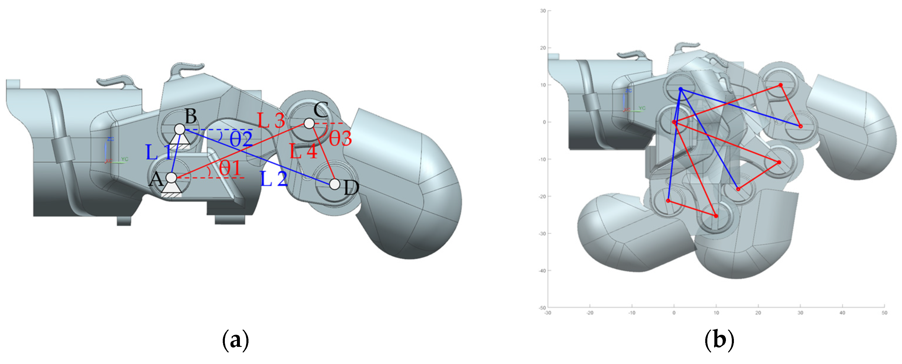
2.2. Kinematic of Linkage Structure

In order to analyze and simulate the movement of the finger prosthesis for partial amputees, a four-link-structure-based kinematic model was used. As shown in Figure 3a, the first link of the prosthesis is fixed, the lower joint connecting to the second link on the first link is referred to as A , and the upper joint connecting to the third link on the first link is called B . The upper joint where the second and fourth links connect is called C , and the remaining joint where the third and fourth links connect is D . With joint A as the origin, the coordinates of joint B are as described in Equation (1).
B x = L 1 cos θ A B B y = L 1 sin θ A B
Here, link L 1 is the distance between joint A and joint B , which is 9 mm, and the angle θ A B between joint A and joint B is set at 80° in the design. Similarly, the coordinates of joint C are as described in Equation (2).
C x = L 3 cos θ 1 C y = L 3 sin θ 1
Link L 3 is the distance between joint A and joint C , which is 27.2 mm, and θ 1 is the angle between joint A and joint C , a variable that can be controlled from 21° in the initial state to a maximum of −60.3° through the pneumatic actuator connected to the finger prosthesis. The coordinates of joint D are as described in Equation (3).
D x = B x + L 2 cos θ 2 D y = B y + L 2 sin θ 2
Link L 2 is the distance between joint B and joint D , which is 30.2 mm, and θ 2 is the angle between joint B and joint D . Since we already know from the design process that link L 4 is the distance between joint C and joint D , which is 12.1 mm, we can find θ 2 using the distance formula Equation (4) of the two points, joints C and D . However, θ 2 appears as a very complex result, as shown in Equation (5), where # denotes a complex equation.
D x C x 2 + D y C y 2 = L 4 2
θ 2 = log L 1 L 3 + L 1 2 + L 2 2 + L 3 2 L 4 2 e θ 1 i + L 1 L 3 e 2 θ 1 i i #
Joint D , which is shared by links L 2 and L 4 , must be constrained together; the constraint equation is shown in Equation (6), and through this equation we can obtain θ 3 . The equation for θ 3 is shown in Equation (7), and the result of the simulation is shown in Figure 3b.
D x = C x + L 4 c o s ( θ 3 ) D y = C y L 4 s i n ( θ 3 )
θ 3 = cos 1 D x C x L 4 = s i n 1 ( D y C y L 4 )

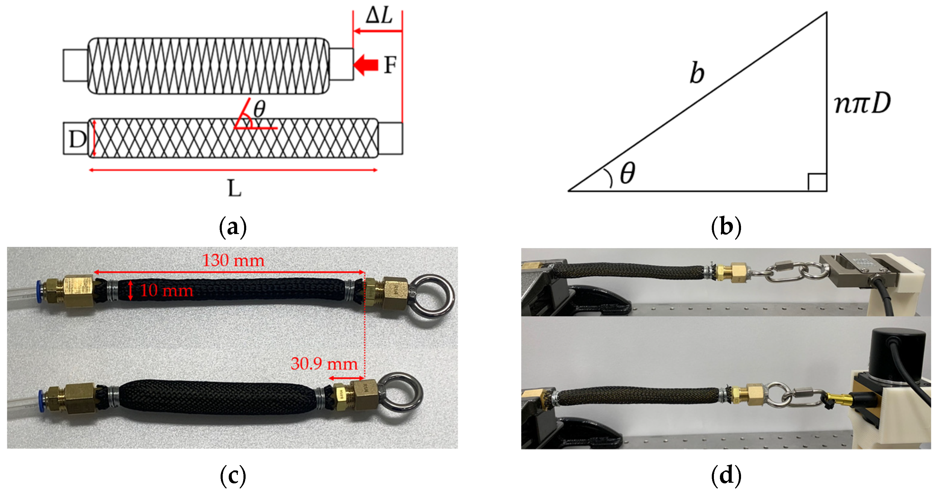
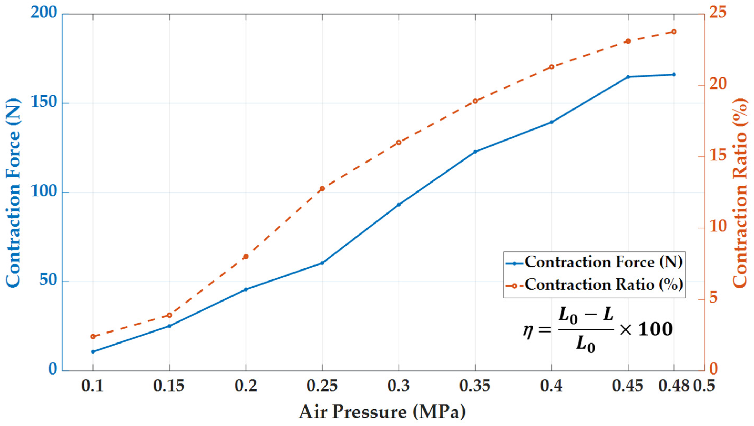
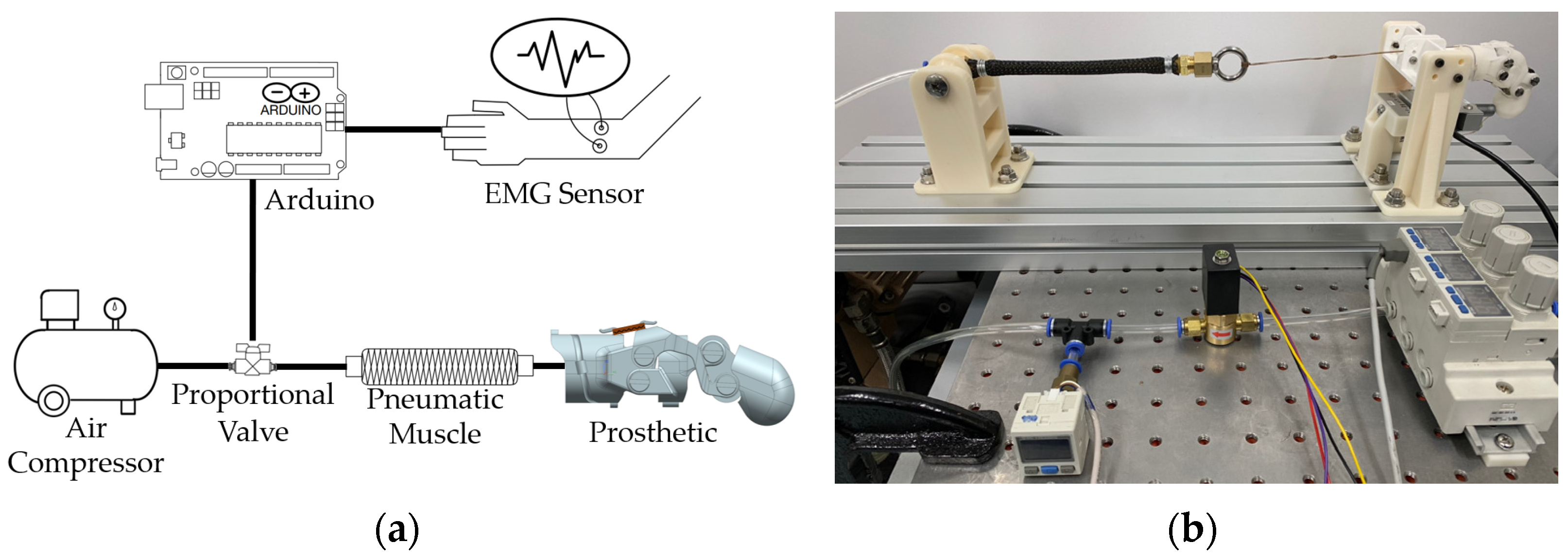
2.3. Pneumatic Actuator

The McKibben muscle is an actuator that converts pneumatic energy into mechanical energy by transforming the pressure applied inside an elastic tube into tensile force in the direction of the tube contraction. Chou and Hannaford analyzed a simplified model through theoretical approaches and several experiments to find the relationship between tension, length, and pressure [20]. Based on the law of energy conservation, assuming the actuator is in an ideal state, the physical model in a static state can be represented as shown in Equation (8).
F = P d V d L = π D 0 2 P 4 ( 3 cos 2 θ 1 )
Here, F is the axial tension, P is the relative pressure, V is the volume change, and L is the axial displacement. D 0 is the diameter of the actuator when θ is 90°. According to the authors, the tension is linearly proportional to the pressure, and it is a function of θ ( 0 ° < θ < 90 ° ) , reaching maximum contraction when θ = 54.7 ° .
We manufactured a pneumatic actuator with a diameter of 10 mm and a length of 130 mm, as shown in Figure 4c. As shown in Figure 4d, we measured the tension and axial length change of the actuator according to the pressure, and the results are shown in Figure 5. The maximum axial length change is L = 30.9   m m when the pressure of the actuator is 0.48 MPa. The physical model for the manufactured actuator can be represented as follows, by applying Equation (8).
F = π D 2 P 4 ( 3 cos 2 θ 1 s i n θ 1 )
Here, D is the current diameter of the actuator, and the error between the modeling value and the experimental value is shown in Table 2. The maximum pressure P of the actuator was determined as 0.4 MPa, at which the manufactured finger prosthesis achieves maximum bending.

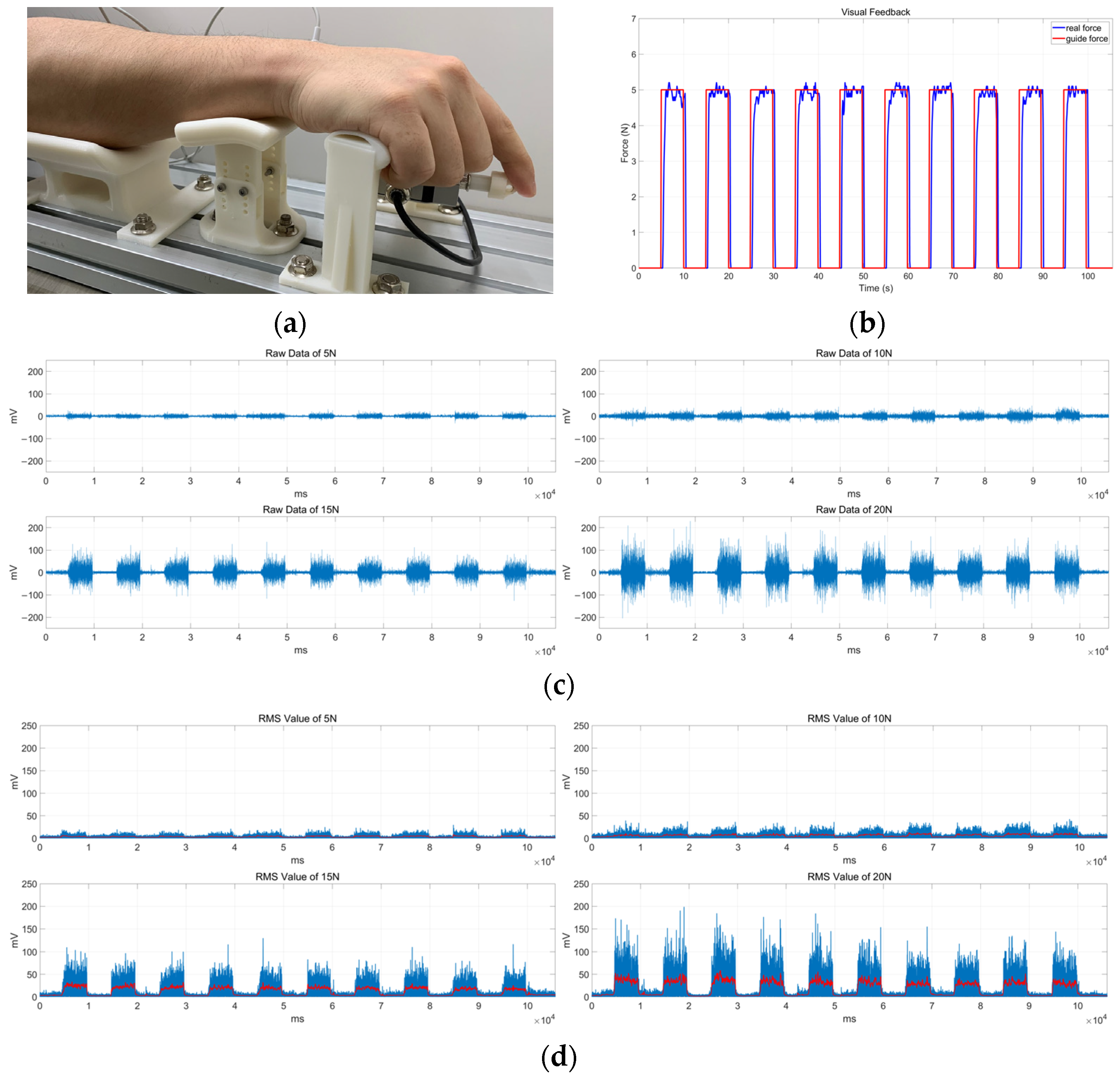
3. EMG Signal According to Grip Force

In order to control the finger prosthesis based on electromyography (EMG) signals, it is necessary to measure how the EMG signals change according to the degree of grip force. For this study, five subjects (four males and one female) participated, as shown in Table 3. Since the flexion of the finger is controlled by the flexor digitorum muscle located on the anteromedial surface of the ulna, electrodes for sEMG were closely attached to the test subject’s flexor digitorum to measure the myoelectric signals.
To prevent unnecessary EMG signals from movements of the elbow or wrist, the test subject’s arm was positioned on each stand as shown in Figure 6a, with their hand lightly placed on the handle. Then, we conducted calibration by utilizing visual feedback to ensure that the subject exerted a consistent force when bending their index finger through a load cell (CUU3-5kgf, SensorSolution, Daegu, Republic of Korea), as shown in Figure 6b. The EMG signals were measured as shown in Figure 6c.
The effective bandwidth of the sEMG signal is known to be approximately 0.5 kHz, and sampling was conducted at 1 kHz according to the Nyquist sampling theorem [23]. Also, the test subject generated signals 10 times for 5 s each in a set of experiments, and this was repeated for five sets. The sampled signals were evaluated in size by the root mean square (RMS), as shown in Figure 6d.
σ = 1 N i = 0 N 1 x N 2

4. Grip Force Experiment

4.1. Experimental Setup

For our experiments, we installed a regulator (arm11BB3-308-A-N, SMC, Tokyo, Japan) on an air compressor (DC991, TICHOT, Hangzhou, China), as shown in Figure 7, and maintained it at 0.7 MPa. When the subject generated the EMG signal, the magnitude was assessed using an Arduino UNO. This estimated signal magnitude was then proportionally converted to a voltage range (0 V~5 V) to control the proportional control valve (KPCV, KCC CO., Ltd., Seoul, Republic of Korea).
The valve opens based on the input voltage and injects air into the fabricated pneumatic actuator. As the air-injected actuator changes length, it pulls the wire of the finger prosthesis, enabling the prosthesis to function. At this point, the force exerted by the end of the prosthesis pressing on the load cell is measured.

4.2. Experimental Results

The upper graph in Figure 8 represents EMG raw data, while the bottom graph depicts RMS data. EMG signals were generated following visual feedback, with the electrode attached to the flexor digitorum muscle, just like in the previous experiments. The size of the signal was evaluated by RMS, and accordingly, pneumatic pressure was applied to the actuator.
The results of the experiment can be seen in Table 4. When the RMS was between 3 mV and 5 mV, a minimum pressure of 0.1 MPa was applied to the actuator when the EMG signal was applied. For larger EMG signals, the pneumatic pressure could be applied in a continuous manner, and at this time, pressure changes less than 20 kPa have a minimal effect on the length change of the actuator, so minor changes in RMS values can be ignored.
A prototype of a finger prosthesis for partial amputees was manufactured using a 3D printer with Duraform PROXPA (Nylon12) material. However, due to the limitations of the material, it was difficult to measure the force at pressures above 0.25 MPa.

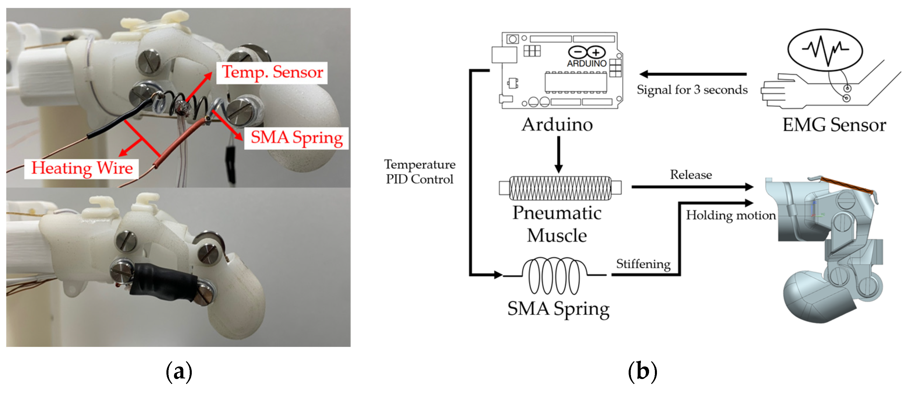
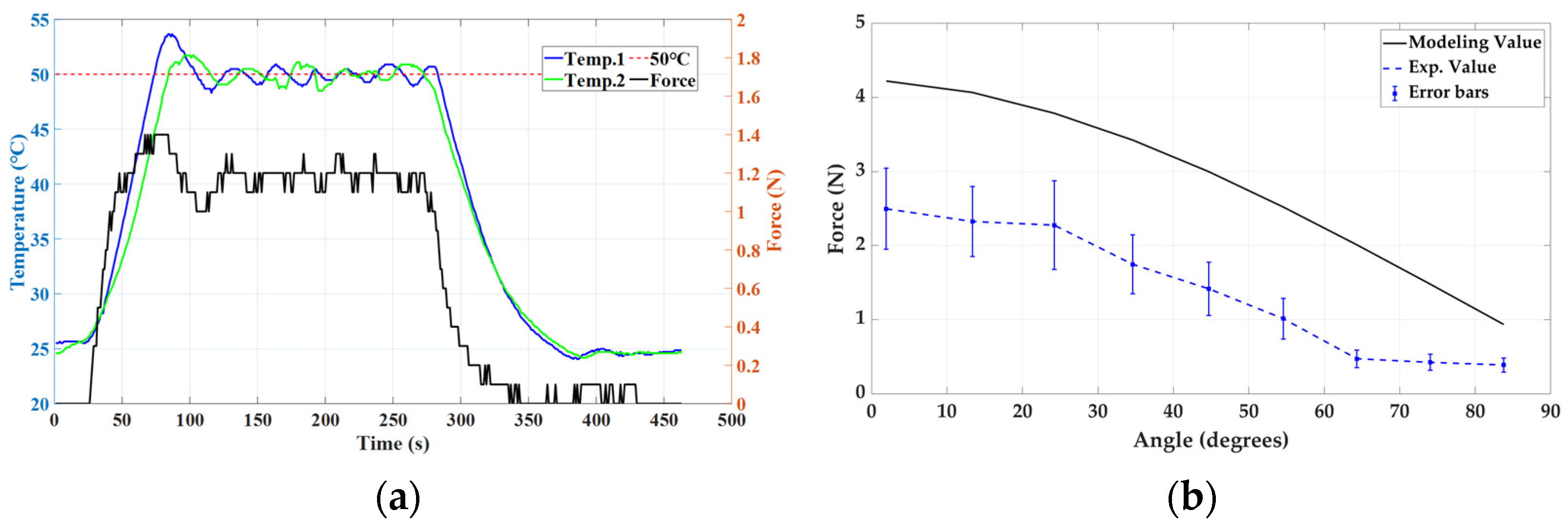
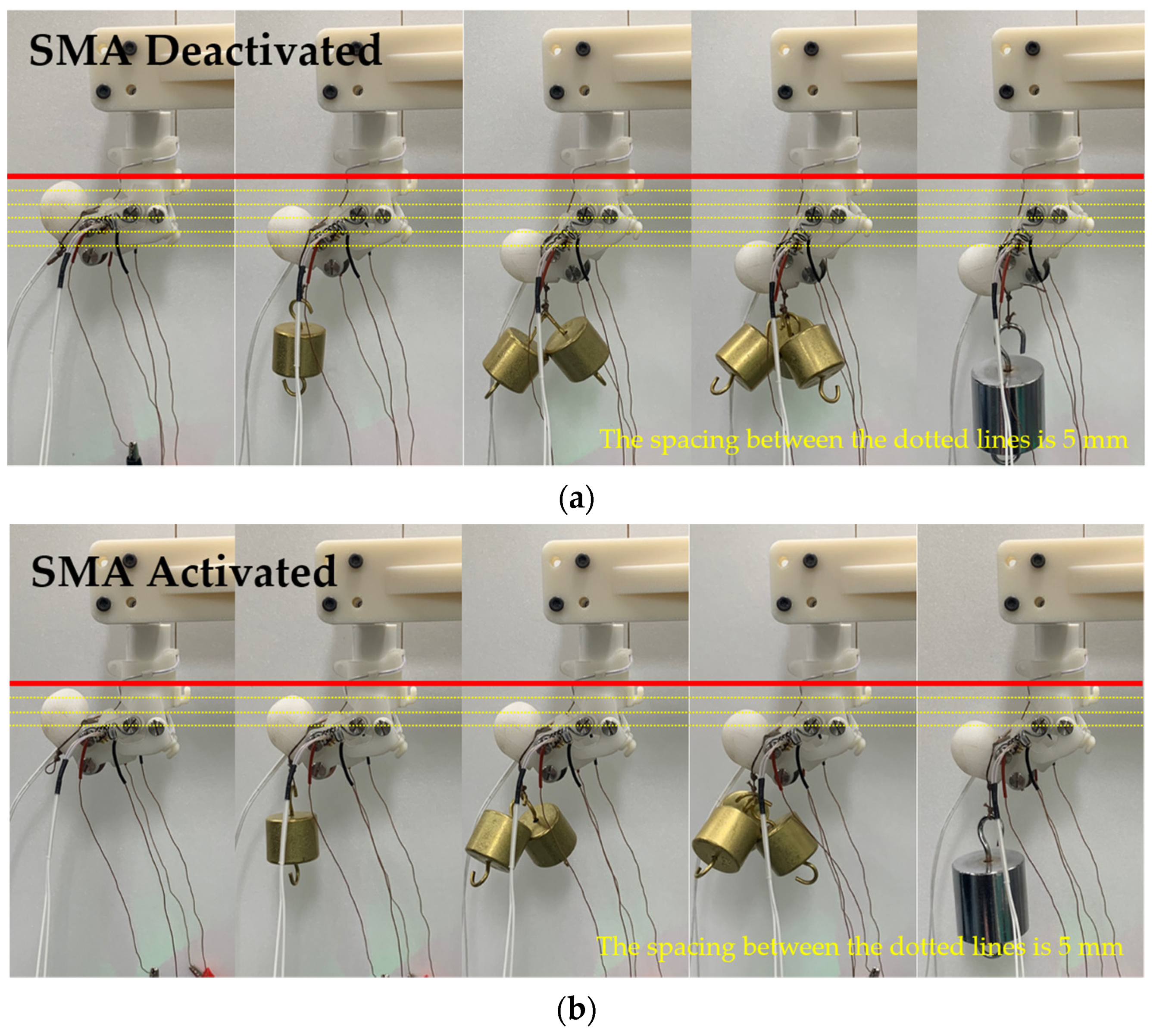
4.3. Stiffness Modulation Using SMA Spring

A shape-memory alloy (SMA) spring was inserted into both joints A and D of the existing finger prosthesis to create a variable stiffness mechanism for a finger prosthesis for partial amputees, as shown in Figure 9a. The parameters of the SMA spring we used is shown in Table 5. Each spring consisted of four coils. When the spring was heated, some of the coils were covered with a silicone tube to prevent any impact on the prosthesis made by a 3D printer. A temperature sensor was attached at the midpoint of the SMA spring to measure the temperature.
The variable stiffness method using an SMA spring is shown in Figure 9b. When the EMG signal is maintained at a certain level or higher for more than 3 s, the temperature of the SMA spring is increased to an operating temperature of 50 °C through PID control to convert it into a fully austenite state. Then, the stiffness of the finger prosthesis increases while being bent, so even if the EMG signal decreases, the SMA can assist the gripping force. If you apply an EMG signal above a certain level again, the SMA will start cooling by convection.
When the temperature of the SMA spring T is between T M and T A , the force of the spring can be expressed as follows [24]:
F s ( T ) = G T d 4 8 n D 3 δ L ( θ s )
The parameters can be represented as shown in Figure 10a, δ L ( θ s ) represents the change in the spring’s length from its initial state due to the bending of the finger prosthesis. In this case, because the spring rotates to θ s and changes its length as the finger prosthesis bends, the length L θ s with respect to θ s   can be expressed as follows. It was obtained using regression techniques as shown in Figure 10b.
L θ s = 0.000876 θ s 2 0.181721 θ s + 30.500133
When the spring transitions to the austenite state and becomes activated, it induces the bending of the finger. Assuming that the moment generated at the center of joint B by the SMA spring is equal to the moment generated by the force at the end-effect of the finger prosthesis, it can be expressed as follows:
M = L E F = L 2 2 F s s i n ( θ s θ 3 )
L E = L 2 2 + l 2 2 L 2 l c o s θ E
In Equation (13), L E represents the distance from joint B to the point where the grip occurs, and it can be represented as shown in Equation (14). Here, l represents the distance from joint D to the point where the grip occurs, and θ E represents the angle between L 2 and l .
Consequently, the force exerted by the SMA spring at the end of the finger prosthesis can be represented as follows:
F = 2 L 2 G T d 4 8 n D 3 L θ s L m i n sin θ s θ 3 L 2 2 + l 2 2 L 2 l c o s θ E
Figure 11a shows the temperature of the SMA and the force at the end of the finger when the proximal phalange and the distal phalange form a 90-degree angle. At this point, all external forces other than the SMA spring are excluded, and approximately 1.2 N of force is generated at the end of the finger when the SMA is activated. Figure 11b presents a comparison graph of the theoretical and experimental results according to the spring angle. It is possible to confirm the error between the modeling value and the experimental value because, due to the characteristic of the moment, the value varies greatly even with a small angle or length difference when measured.
As shown in Figure 12, the weight at the end of the finger prosthesis was increased in increments of 50 g from 50 g to 200 g. When 200 g was applied during the activation of the SMA, the end of the prosthesis dropped by approximately 12–13 mm compared with when there was no weight. During the deactivation of the SMA, the end showed a drop of about 24–25 mm.

4.4. Functional Evaluation of Finger Prosthesis

As shown in Figure 13, we conducted a performance evaluation through the pinch grip motion of the finger prosthesis designed for partial amputees. The pinch grip motions were evaluated through eight actions (pulp pinch, diagonal volar grip, lateral pinch, transverse volar grip, tripod pinch, spherical volar grip, five-finger pinch, and extension grip). In the evaluation, we used items ranging from light pens and small tools to heavier items like balls or water bottles that are used in daily life.
Because the user’s upper limb is not entirely amputated, they can still use their remaining fingers and muscles. We confirmed that the developed finger prosthesis can assist the user’s actions. All testing procedures performed in this study were previously approved by the university’s Institutional Review Board (CHAMC 2022-11-053-002), and all participants provided written informed consent.

5. Conclusions

In this study, we developed a wearable finger prosthesis for partial amputees, and this paper presents a kinematic model for the prosthesis. We adopted a McKibben muscle-type pneumatic actuator as our actuator, and applied traditional modeling of pneumatic actuators to the one we manufactured. Since there were discrepancies between the modeling and experimental results, we proposed an adjusted modeling approach and evaluated the performance of the pneumatic actuator.
We also measured EMG signals for each level of force by inducing a specific pinch force on the index finger using visual feedback, which allowed us to control the actuator. The measured signals were evaluated by their RMS size, which in turn controls the proportional control valve as it changes the signal from 0 V to 5 V. After integrating the finger prosthesis for partial amputees with the pneumatic actuator continuously controlled by EMG signals, we measured the pinch force of the prosthesis.
We proposed and tested a mechanism that inserts SMA springs into the joints of the finger prosthesis to change their stiffness, in order to maintain bending motion and assist the pinch force even when the EMG signal decreases. Finally, we evaluated the performance of the prosthesis through eight different pinch grip motions.
If we only extract and amplify the EMG signals of the flexor digitorum muscle to control the actuator, we can ignore many unnecessary signals, such as wrist movement in grip actions, thus greatly increasing the accuracy of actions according to the user’s intention. Therefore, research on mechanisms that can extract signals from specific muscles in real time is needed.
In addition, due to the limitations of the prototype material of the finger prosthesis, we were unable to apply the pressure that generates the maximum bending of the actuator, so in future studies we will design an easier process and consider more durable structures.
Depending on the level and location of an amputation, there can be differences in EMG signals, so extensive collection and analysis of EMG signals from disabled participants through numerous clinical trials are needed. Also, since EMG signals differ from user to user, research on precise calibration to proportionately apply the pressure is required. This would help in customizing the finger prosthesis device to best serve the needs of the individual user, enhancing both the effectiveness and comfort of the device.

Author Contributions

Conceptualization, H.K. and H.C.; methodology, H.K. and H.C.; software, H.K., S.J. and P.T.D.; data curation, H.K., S.J. and P.T.D.; formal analysis, H.K. and C.K.L.; writing—original draft preparation, H.K., B.A. and S.K.; writing—review and editing, H.C. and Y.K.; supervision, H.C. and Y.K.; project administration, Y.K.; funding acquisition, Y.K. All authors have read and agreed to the published version of the manuscript.

Funding

This work was supported by Incheon National University Research Grant in 2020.

Institutional Review Board Statement

The study was conducted in accordance with the Declaration of Helsinki and approved by the Institutional Review Board of Cha University (Bundang Medical Center) (IRB File No. CHAMC 2022-11-053-002).

Data Availability Statement

Data are contained within the article.

Conflicts of Interest

The authors declare no conflict of interest.

References

  1. Dunai, L.; Novak, M.; García Espert, C. Human hand anatomy-based prosthetic hand. Sensors 2020, 21, 137. [Google Scholar] [CrossRef] [PubMed]
  2. Murali, B.; Huddle, S.; Weir, R.F.F. Design and evaluation of a distally actuated powered finger prosthesis with self-contained transmission for individuals with partial hand loss. Adv. Mech. Eng. 2019, 11, 1687814019834114. [Google Scholar] [CrossRef]
  3. Ryu, W.; Choi, Y.; Choi, Y.J.; Lee, S. Development of a lightweight prosthetic hand for patients with amputated fingers. Appl. Sci. 2020, 10, 3536. [Google Scholar] [CrossRef]
  4. Sandoval-Gonzalez, O.; Jacinto-Villegas, J.; Herrera-Aguilar, I.; Portillo-Rodiguez, O.; Tripicchio, P.; Hernandez-Ramos, M.; Flores-Cuautle, A.; Avizzano, C. Design and development of a hand exoskeleton robot for active and passive rehabilitation. Int. J. Adv. Robot. Syst. 2016, 13, 66. [Google Scholar] [CrossRef]
  5. Burns, M.K.; Van Orden, K.; Patel, V.; Vinjamuri, R. Towards a wearable hand exoskeleton with embedded synergies. In Proceedings of the 2017 39th Annual International Conference of the IEEE Engineering in Medicine and Biology Society (EMBC), Jeju, Republic of Korea, 11–15 July 2017; pp. 213–216. [Google Scholar]
  6. Ceccarelli, M.; Morales-Cruz, C. A prototype characterization of ExoFinger, a finger exoskeleton. Int. J. Adv. Robot. Syst. 2021, 18, 17298814211024880. [Google Scholar] [CrossRef]
  7. Li, H.; Cheng, L.; Sun, N.; Cao, R. Design and control of an underactuated finger exoskeleton for assisting activities of daily living. IEEE/ASME Trans. Mechatron. 2021, 27, 2699–2709. [Google Scholar] [CrossRef]
  8. Wang, Y.; Zheng, S.; Song, Z.; Pang, J.; Li, J. A coupling dynamic model for studying the physical interaction between a finger exoskeleton and a human finger. IEEE Access 2020, 8, 125412–125422. [Google Scholar] [CrossRef]
  9. Jiang, S.; Chen, B.; Qi, F.; Cao, Y.; Ju, F.; Bai, D.; Wang, Y. A variable-stiffness continuum manipulators by an SMA-based sheath in minimally invasive surgery. Int. J. Med. Robot. Comput. Assist. Surg. 2020, 16, e2081. [Google Scholar] [CrossRef]
  10. Kim, Y.; Cheng, S.S.; Desai, J.P. Active stiffness tuning of a spring-based continuum robot for MRI-guided neurosurgery. IEEE Trans. Robot. 2017, 34, 18–28. [Google Scholar] [CrossRef]
  11. Jeon, H.; Le, Q.N.; Jeong, S.; Jang, S.; Jung, H.; Chang, H.; Pandya, H.J.; Kim, Y. Towards a snake-like flexible robot with variable stiffness using an SMA spring-based friction change mechanism. IEEE Robot. Autom. Lett. 2022, 7, 6582–6589. [Google Scholar] [CrossRef]
  12. Thomas, T.L.; Bos, J.; Huaroto, J.J.; Kalpathy Venkiteswaran, V.; Misra, S. A Magnetically Actuated Variable Stiffness Manipulator Based on Deployable Shape Memory Polymer Springs. Adv. Intell. Syst. 2023, 2023, 2200465. [Google Scholar] [CrossRef]
  13. Kim, J.; Choi, W.-Y.; Kang, S.; Kim, C.; Cho, K.-J. Continuously variable stiffness mechanism using nonuniform patterns on coaxial tubes for continuum microsurgical robot. IEEE Trans. Robot. 2019, 35, 1475–1487. [Google Scholar] [CrossRef]
  14. Le, Q.N.; Kim, H.; Jeong, S.; Chang, H.; Pandya, H.J.; Kim, Y. Development of a Variable Stiffness Modulating Mechanism Based on Phase-Change Material and a Temperature Control System. Int. J. Precis. Eng. Manuf. 2022, 23, 517–531. [Google Scholar] [CrossRef]
  15. Wang, H.; Chen, Z.; Zuo, S. Flexible manipulator with low-melting-point alloy actuation and variable stiffness. Soft Robot. 2022, 9, 577–590. [Google Scholar] [CrossRef]
  16. Kim, H.; Kim, S.J.; Park, J.; Chang, H.; Kim, N.; Kim, Y. Development of Particle Flow-Based Inflatable Robot Body for Shape Rigidity Modulation. Int. J. Precis. Eng. Manuf. 2020, 21, 1857–1864. [Google Scholar] [CrossRef]
  17. Koh, J. Design of Shape Memory Alloy Coil Spring Acuator for Improving Performance in Cyclic Actuation. Materials 2018, 11, 2324. [Google Scholar] [CrossRef]
  18. An, S.-M.; Ryu, J.; Cho, M.; Cho, K.-J. Engineering design framework for a shape memory alloy coil spring actuator using a static two-state model. Smart Mater. Struct. 2012, 21, 055009. [Google Scholar] [CrossRef]
  19. Andrianesis, K.; Tzes, A. Development and control of a multifunctional prosthetic hand with shape memory alloy actuators. J. Intell. Robot. Syst. 2015, 78, 257–289. [Google Scholar] [CrossRef]
  20. Chou, C.-P.; Hannaford, B. Measurement and modeling of McKibben pneumatic artificial muscles. IEEE Trans. Robot. Autom. 1996, 12, 90–102. [Google Scholar] [CrossRef]
  21. Kurumaya, S.; Nabae, H.; Endo, G.; Suzumori, K. Design of thin McKibben muscle and multifilament structure. Sens. Actuators A Phys. 2017, 261, 66–74. [Google Scholar] [CrossRef]
  22. Neumann, D.A. Kinesiology of the Musculoskeletal System: Foundations for Rehabilitation, 3rd ed.; Elsevier Health Sciences: Philadelphia, PA, USA, 2016; pp. 277–336. [Google Scholar]
  23. Van Boxtel, A. Optimal signal bandwidth for the recording of surface EMG activity of facial, jaw, oral, and neck muscles. Psychophysiology 2001, 38, 22–34. [Google Scholar] [CrossRef] [PubMed]
  24. Do, P.T.; Le, Q.N.; Luong, Q.V.; Kim, H.-H.; Park, H.-M.; Kim, Y.-J. Tendon-Driven Gripper with Variable Stiffness Joint and Water-Cooled SMA Springs. Actuators 2023, 12, 160. [Google Scholar] [CrossRef]
Figure 1. Schematic representation of the concept of partial finger prosthesis. (a) Concept 1: Daily use. (b) Concept 2: When the user constantly needs grip force.
Actuators 12 00434 g001
Figure 2. (a) Structural modeling of partial finger prosthesis. (b) Finger prosthesis prototype. (c) Human finger movement. (d) Finger prosthesis movement.
Actuators 12 00434 g002
Figure 3. (a) Variable of four-bar linkage. (b) Result of simulation.
Actuators 12 00434 g003
Figure 4. (a) Schematic of McKibben muscle. (b) The angle between the center line and textile θ , textile length b, the number of turns of textile n, diameter of actuator D. (c) Manufactured pneumatic actuator; deflation and inflation ( P M A X = 0.4   M P a ). (d) Experimental setup to measure the force (CSBA-100k, Sensor solution, Republic of Korea) and length (CNH-500, COZY INTERNATIONAL, Seoul, Republic of Korea) of the actuator.
Actuators 12 00434 g004
Figure 5. Experimental result of axial tension and length according to pressure.
Actuators 12 00434 g005
Figure 6. (a) Experimental setup to measure EMG signal. (b) Experimental result using visual feedback. (c) Measured raw sEMG data using visual feedback. (d) The result of RMS.
Actuators 12 00434 g006
Figure 7. (a) Schematic representation of the experimental setup. (b) Experimental setup.
Actuators 12 00434 g007
Figure 8. Grip force results of a user’s EMG signal change.
Actuators 12 00434 g008
Figure 9. Experimental setup. (a) Finger prosthesis with SMA spring. (b) Schematic of experiment.
Actuators 12 00434 g009
Figure 10. (a) Free body diagram of a finger prosthesis. (b) Regression of spring length based on spring angle.
Actuators 12 00434 g010
Figure 11. (a) Temperature control and end-effect force when the proximal phalange and the distal phalange form a 90° angle. (b) Comparison graph of mathematical and experimental values.
Actuators 12 00434 g011
Figure 12. Finger angle change with weight. (a) SMA deactivated; (b) SMA activated.
Actuators 12 00434 g012
Figure 13. Functional testing of finger prosthesis; (a) Pulp pinch; (b) Diagonal volar grip; (c) Lateral pinch; (d) Transverse volar grip; (e) Tripod pinch; (f) Spherical volar grip; (g) Five-finger pinch; (h) Extension grip.
Actuators 12 00434 g013
Table 1. Specifications of the existing prosthetic/robotic hands and the finger prosthesis developed in this study.
Developer [Ref.]Actuator TypeMaximum AngleFingertip Maximum ForceWeight
Mural [2]DC MotorMCP 70°
PIP 90°
DIP 60°
6.056 ± 0.396 N43.5 g
Ryu [3]DC MotorMCP 90°
PIP 90°
DIP 90°
6.460 ~ 7.487 N152.32 g
(Except Thumb)
Gonzalez [4]DC Motor--731 g
Burns [5]Two MotorsMCP 44 ± 5.3°
PIP 36.7 ± 5°
-1134 g
Ceccarelli [6]Servo MotorsMCP 37.6°
DIP 115.99°
--
Li [7]DC MotorsMCP 87.37°
PIP 84.16°
DIP 82.08°
12.3 N127 g
Wang [8]SMA WireMCP 37.5°
PIP 42°
DIP 29.5°
--
This StudyPneumaticPIP 90°
DIP 65°
6.5 ± 0.3 N25 g
(80 g including actuator)
SMA Spring1.2 N
Table 2. Result of actuator test.
Air Pressure, P
(MPa)
Diameter, D
(mm)
The Angle between the Center Line and Textile, θ
(degree)
Error between Experimental and Model Values
(%)
0.1011.8227.57
0.1513.12513.07
0.2014.7325.74
0.2516.4387.66
0.3018.8423.82
0.3520.2463.53
0.4021.1493.15
Table 3. Subjects’ information.
No.AgeSex
Sub 124Male
Sub 226Male
Sub 330Male
Sub 431Male
Sub 526Female
Table 4. Result of Experiment.
RMS (mV)Air Pressure (kPa)Grip Force of Prosthesis (N)
4 ± 11000.7 ± 0.2
7 ± 2118 ± 122.2 ± 0.3
16 ± 3172 ± 184.3 ± 0.2
26 ± 2232 ± 126.5 ± 0.3
Table 5. Parameters of the SMA spring.
ParameterSymbolValue
MaterialNiTi-45Nitinol
Spring diameterD6.5 mm
Wire diameterd0.75 mm
Original length L m i n 3 mm
Maximum length L m a x 30.1 mm
Number of coilsn4
Shear modulusG16.5 GPa
Activation temperature 50 °C
Disclaimer/Publisher’s Note: The statements, opinions and data contained in all publications are solely those of the individual author(s) and contributor(s) and not of MDPI and/or the editor(s). MDPI and/or the editor(s) disclaim responsibility for any injury to people or property resulting from any ideas, methods, instructions or products referred to in the content.

