
Practical Adaptive Fast Terminal Sliding Mode Control for Servo Motors


1
Faculty of Science, Engineering and Technology, Swinburne University of Technology, Melbourne 3122, Australia
2
Department of Automated Manufacturing, Al Khwarizmi College of Engineering, University of Baghdad, Baghdad 10071, Iraq
*
Author to whom correspondence should be addressed.
Actuators 2023, 12(12), 433; https://doi.org/10.3390/act12120433
Submission received: 20 October 2023
/
Revised: 14 November 2023
/
Accepted: 21 November 2023
/
Published: 22 November 2023
(This article belongs to the Section Control Systems)
Abstract
:Position control of servo motor systems is a challenging task because of inevitable factors such as uncertainties, nonlinearities, parametric variations, and external perturbations. In this article, to alleviate the above issues, a practical adaptive fast terminal sliding mode control (PAFTSMC) is proposed for better tracking performance of the servo motor system by using a state observer and bidirectional adaptive law. First, a smooth-tangent-hyperbolic-function-based practical fast terminal sliding mode control (PFTSM) surface is designed to ensure not only fast finite time tracking error convergence but also chattering reduction. Second, the PAFTSMC is proposed for the servo motor, in which a two-way adaptive law is designed to further suppress the chattering and overestimation problems. More importantly, the proposed adaptive technique can update the switching gain according to the system uncertainties, which can provide high gain in the reaching phase and then decrease to the smallest value in the sliding phase to avoid the monotonically increasing gain that exists in most adaptation methods. Third, the finite-time stability of the closed-loop system is proved based on the Lyapunov theorem. Finally, the simulation studies and experimental tests verify the effectiveness of the proposed control in terms of better tracking, strong robustness, and reduced chattering, compared to existing algorithms.
1. Introduction
Servo motors have been extensively used in position control of industrial actuators such as robotic arms, conveyor belts, camera autofocus, solar tracking systems, etc., because of their many advantages, including energy efficiency, cost-effectiveness, a simple design, and high power-to-weight ratios [1,2,3]. Moreover, servo motors can be operated at low speed or even in reverse to increase the accuracy of actuators. However, achieving greater accuracy in the control of the servo motor position is challenging due to various uncertainties, nonlinearities, and disturbances that may come from the compressibility of air, backlash, or other friction forces. Moreover, due to these factors involved with servo motors, their position tracking errors would increase and necessitate more control input voltages for robust tracking performance [4,5,6]. Therefore, to enhance the performance of servo motors, a robust controller must be designed, which can mitigate the effects of these uncertainties and disturbances.
Over the past decade, numerous control strategies have been designed to suppress the negative effects of nonlinearities and uncertainties in servo motors, such as PID control [7], active disturbance rejection control [8], adaptive control [9], observer-based controllers [10], sliding mode control (SMC) [11], and so on. Among them, SMC is a robust control strategy and has been extensively utilized in a broad range of applications, such as industrial actuators, robotics, power electronics, biomedical, and aerospace [12,13,14,15,16,17,18,19]. However, the SMC method has a few drawbacks, such as asymptomatic output convergence, which is not desirable for accurate control of the servo motor. To overcome the asymptomatic convergence problem, TSMC has been designed in [20] to provide a finite time convergence of the controlled system output, but the TSMC has singularity issues that are not suitable for practical systems because of immense control input. To tackle the singularity issues in the TSMC, a nonsingular TSMC (NTSMC) method is proposed in [21], but it comes at the cost of chattering as the conventional SMC and TSMC methods could damage the servo motor by providing saturation in the control input.
To reduce the chattering in the SMC, TSMC, and NTSMC methods, different control strategies are proposed, including disturbance-observer-based control, higher-order SMC, fractional-order SMC, and filter-based control [22,23,24,25,26]. More interestingly, several adaptive laws are proposed for a chattering reduction in the SMC strategies, like monotonically increasing adaptive gains and bidirectional adaptive gains [27]. However, monotonically adaptive gains increase until the states of the system reach zero, and maintaining a gain causes it to become larger, which is a reason for gain overestimation. To solve this overestimation, a bidirectional adaptive-gains technique is proposed in [28,29,30], which increases during the reaching phase to minimize large tracking errors and decreases to the smallest value in the sliding phase to lessen chattering, but only asymptomatic convergence is provided instead of finite time. In [31], a fast NTSMC (FNTSMC) is introduced for finite-time convergence with reduced chattering by using a continuous terminal reaching phase. Compared to the work [31] that compromises between tracking accuracy and chattering reduction, another work of the FNTSMC strategy is proposed in [32] to relax this compromise, but the switching gains adopted in this work are constant.
To address the above drawbacks of existing finite-time control algorithms, this paper proposes a practical adaptive fast terminal sliding mode control (PAFTSMC) strategy with an adaptation gain for the servo motor considering external disturbances, nonlinearities, and uncertainties. In addition, a smooth function is used in constructing a sliding manifold to reduce the chattering of the control algorithm. The important contributions of this paper are as follows:
- A practical fast terminal sliding mode (PFTSM) surface is modified to ensure not only fast finite time convergence but also chattering reduction in a servo motor.
- A bidirectional adaptive law for switching gain is constructed and used with the proposed control law of the PFTSM to lessen the chattering caused by high constant gain in the conventional TSMC. The switching gain tuned by the proposed adaptive law varies according to uncertainties. This adaptation method provides large gain in the reaching phase when system states are far away from the origin of sliding manifolds and then moves to the smallest values in the sliding phase when states are near to the origin. Moreover, the gain overestimation problem of monotonically adaptive law is being solved by the proposed bidirectional adaptive law.
- By using the Lyapunov theorem, the finite time stability is proved for the whole closed-loop control system under the proposed practical adaptive fast terminal sliding mode control (PAFTSMC) law.
The rest of the work is organized like this: Section 2 presents the mathematical modeling of a brushless DC servo motor. Section 3 demonstrates the design of the control law, construction of the bidirectional adaptive law, design of the state observer, and finite-time stability proof. Furthermore, the comparison studies based on simulations and experiments are included in Section 4. The conclusion for this article is located in Section 5.
2. Mathematical Modeling of the Servo Motor System
In this section, the modeling of the brushless DC servo motor system is provided by the following state space form [35]:
with
where = , = = denote the states of the DC servo motor system, involving the motor angular position and the angular velocity , is the moment of inertia of drive disk, is the gear radius of drive disk, is the viscous damping of the drive disk, is the radius of gear connected to the speed reducer, and is the moment of inertia of the speed reducer.
With external disturbances and lumping parametric system uncertainties together in one time term called the total disturbance , the dynamical servo motor in (1) can be reformulated as follows:
with
where represents the system state vector, and are the nominal part of b and , respectively. Moreover, and are the uncertain elements of b and , respectively. Note that the control constant and the system function is .
The primary control aim of this work is to devise a robust motion controller such that the angular motion of the brushless DC servo motor can follow the desired rotational trajectory quickly and precisely, even considering external disturbances and model uncertainties.
Assumption 1.
For the dynamics (2), we assume that the overall lumped disturbances of the DC servo motor are bounded by the following boundedness , where the bounded constant is .
3. Proposed Control Design and Stability Proof
Here, a sliding surface, an adaptive law, and a control law of the proposed method are first designed to attain rapid convergence and better tracking accuracy. Second, the servo motor system stability actuated by the proposed method is analyzed by using the Lyapunov theorem. Figure 1 illustrates the block diagram of the entire design of the PAFTSMC for the servo motor (2), in which we design the PFTSMC based on the novel adaptive law for the position tracking trajectory of the servo motor with the help of the finite time state observer (FTSO).
3.1. Design of PAFTSMC Approach
For the dynamical servo motor (2), the angular position and velocity tracking error are defined as
where and are the desired position and velocity angle command. Accordingly, the tracking error dynamics of the servo motor (2) can be described as
where is the system error vector, and is the second derivative of the desired reference . Note that the sign “t” in front of some variables is omitted for the sake of brevity in the subsequent control design and stability procedure. The following lemma is provided in advance as preparation before deriving finite-time stability and its settling time in this paper.
Lemma 1.
Let , and , and always be held if the following formula
holds. At a finite time, the errors of the system (4) are driven quickly into a partial-flat region that is a small neighborhood around the equilibrium point and then asymptotically converge to the origin. To be more exact, the physical interpretation is as follows: the approximate dynamics become when is far away from zero, and the fast convergence at far away from zero is better understood. Based on [36], the terminal attraction is , which is the approximate dynamics when is approached. For sliding to the partial-flat region, the finite-time is provided by
where is the finite time when the sliding function (5) is accomplished, , and .
Proof.
If the sliding surface defined in (5) has arrived, the system error dynamics in (4) can be obtained by the nonlinear differential equation as follows:
Choosing the Lyapunov function and then differentiating with respect to time yields
and the sign “=” holds if and only if . As the inequality in (8) is held and the scalar function is radial unbounded, the system error dynamics (4) are globally asymptotically stable.
By integrating the proposed reduced-order dynamics in (7), the finite time can be obtained as follows:
This proof is completed. □
Motivated by the outstanding advantages of the practical TSMC [11], for ensuring the fast finite time convergence and accurate tracking efficiency, by using a smooth function , a PFTSM surface for the dynamical plant error (4) is newly constructed as
where is the estimated velocity tracking error, in which the angular velocity of shall be estimated by the state observer as designed later on in the dynamics (16), and > 0 and > 0, are the sliding surface gains, and > 0 is used to adjust the steepness of the function.
Now, taking the first derivative of the PFTSM manifold (10) yields
When the sliding surface function and derivative of that function approach zero in finite time as in , the equivalent law of the PAFTSMC is obtained by
where the nominal system function is calculated by as formulated in (1) and shall be estimated by the state observer as designed later on in the dynamics (16).
In order to ensure the chattering reduction and robustness against the external disturbances and system parametric uncertainties, with satisfying the reaching condition , a two-way adaptive reaching law is proposed by using two nonlinear terms as a function of the position tracking error and sliding surface as follows:
where the function is the adaptive switching gain designed by using the following adaptation law
where , , , and . Based on (14), when the system trajectories are far away from the origin of the sliding manifolds, then, because of the large error, the term will have a large value of gain in the reaching phase to speed up the convergence. On the other hand, if system trajectories are close to the origin of the sliding surface, implying that the servo motor system errors decrease to smaller values, the term will provide a small gain during the sliding phase. Hence, by combined effect of these two terms in the proposed adaptive reaching law, it can suppress the control chattering and enhance the faster convergence as compared to traditional reaching laws.
For the servo motor error dynamics (4) and the sliding surface designed by (10), the equivalent control effort determined by (12), and the switching control effort obtained by (13), then the total control effort of the PAFTSMC is designed by
which guarantees the servo error trajectories in (3) converge to zero in finite time.
3.2. State Observer Design
It should be noticed that the whole information of the actual servo motor (2) is hard to obtain; e.g., the servo motor angular position is always measured by the existing encoder. However, the information on angular velocity is not available. In this case, a state observer is needed to estimate the unmeasured velocity for meeting the requirement of our control design [37].
Regarding the dynamics (2), only the position variable is available, and assume that the nominal function is bounded. Thus, the FTSO can be utilized as
where and are the estimated states of the states and , is the state observer fractional power, and the observer gain can be chosen by following the Hurwitz stable characteristics function
where is the state observer’s bandwidth.
3.3. Stability Analysis
In this part, we analyze the stability of the closed-loop servo motor system under the proposed PAFTSMC as follows:
Theorem 2.
Proof.
In terms of , the Lyapunov function is described as follows
With respect to time, is differentiated as follows:
According to (10), the derivative of is taken as
Here, , , and . Now, we consider two cases under the adaptation gain in (14) to prove the finite time stability. Firstly, when the servo motor dynamics are far from the sliding surface, increases the rate of convergence and by selecting . Secondly, in the sliding phase, plays a significant role in quicker arrival at the sliding manifold by selecting . From the above two cases, the finite time stability of the proposed controller can be ensured by implying . Thus, in this way, the stability of the control law has been proved by using the Lyapunov function. □
4. Simulations and Experimental Results with Discussion
In order to validate the outcome and assess the merits of the proposed control law (15), we compare the proposed scheme with two comparative control systems. These comparisons are carried out in a simulative and practical manner on the servo motor considering the sensor noise measurement, uncertainties of the system, and load variation. For the first comparison, we use ITSMC [33] to validate the proposed sliding surface. For the second comparison, ASMC [34] has been applied to highlight the benefits of the proposed adaptive law. In simulations and experiments, the industrial plant emulator [38] is modeled as a rigid body plant that consists of a brushless DC servo motor and is considered as
with
Here, there are two controllers for comparison purposes as follows:
The first comparative controller is the ITSMC scheme [26], in which its equivalent control input is designed as follows:
and its switching control input is designed as follows:
with
where , is a positive constant, and are constant gains, and and fractional powers of the terminal sliding surface.
The second controller is the ASMC scheme [27], in which its equivalent control input is designed as follows
and the switching control input of the ASMC is designed as follows:
with
where k > 0, > 0, and > 0 are constants, and > 0 is the sliding surface gain. The control parameters of comparative and proposed controllers are listed in Table 1.
Remark 1.
For a fair comparison, the gains of the PAFTSMC and comparative controllers must be carefully chosen. Therefore, we select these gains to maintain the same control input for all controllers. By adjusting these controller gains, chattering and accuracy are traded off. Firstly, increasing control by tuning the gains might speed up tracking error convergence, but too much chattering could result. Secondly, while increasing switching gains can improve controller performance, they may also result in an increase in control input bandwidth and higher controller chattering. Additionally, the proposed controller switching gains are updated using the adaptive law ; initially, this law provides high gain in the reaching phase and then switches to small gain for the sliding phase to reduce the chattering in the control loop.
4.1. Simulation Results Analysis
In this section, simulation comparisons are discussed between the proposed PAFTSMC and two comparative controllers of ITSMC [26] and ASMC [27] applied on the DC servo motor. The control parameters in Table 1 are selected so that the bandwidth of all controllers’ input is kept approximately the same for a fair comparison. There are three cases of simulations in Figure 2, Figure 3 and Figure 4 that are carried out; one is under as desired reference signal including belt, noise, and full payload on the drive disk of the system. The second case is under dual sine wave as desired reference signal with the same disturbances as in the first case. Besides, the third case is under as the desired reference and the external disturbance assumed by .
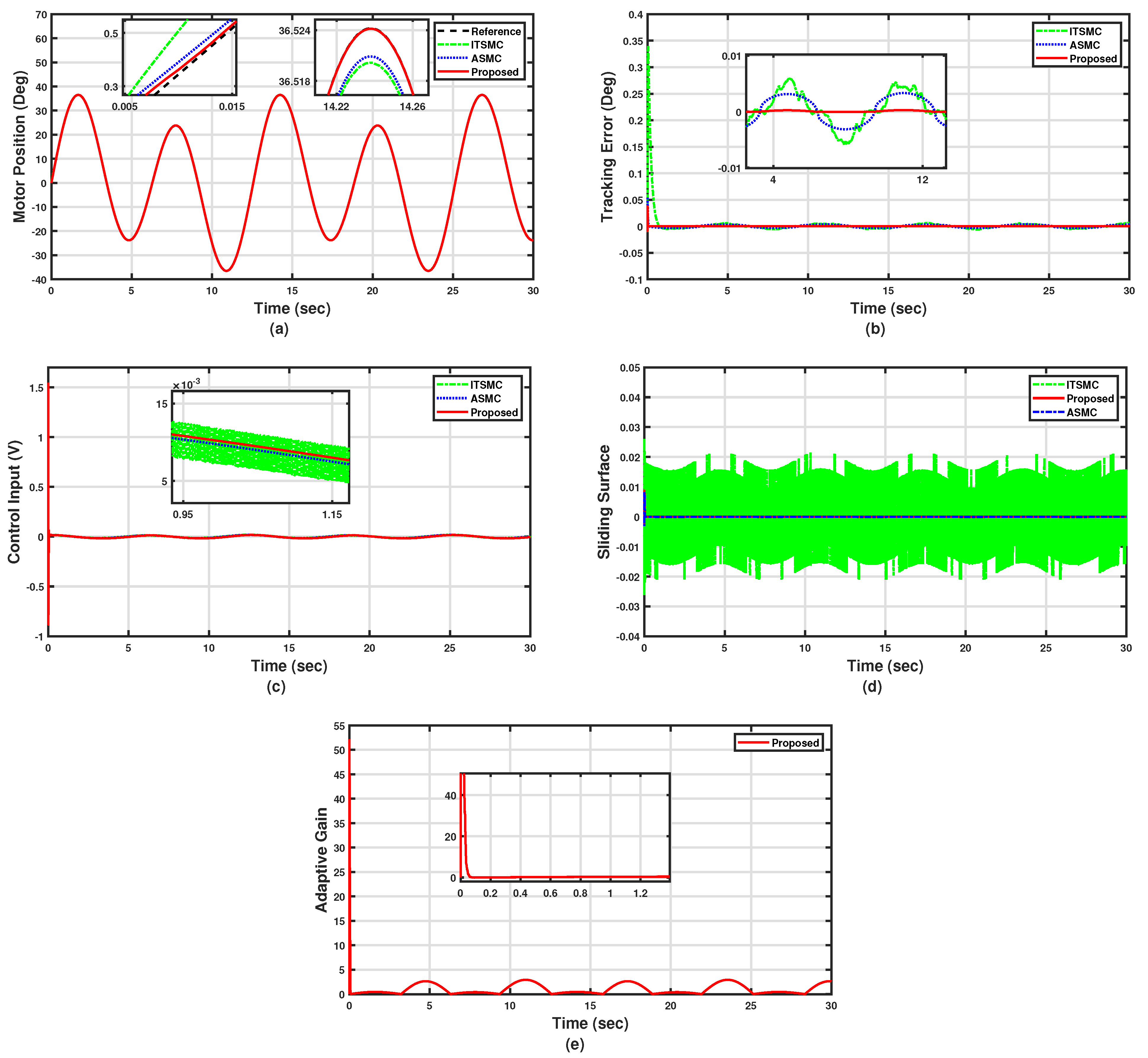
Case 1: The simulation results of Case 1 are shown in Figure 2 using as the desired reference. Figure 2a,b show that the proposed PAFTSMC has better position tracking as compared to the ITSMC and ASMC under the circumstances of noise and payload variation. Additionally, the efficiency of the PAFTSMC is confirmed by showing the sliding surface and control input. Figure 2c clearly demonstrates that the proposed PAFTSMC exhibits lower chattering than others. Figure 2d shows that the sliding surface under the proposed method has fewer oscillations and less chattering and close convergence to zero compared to other methods. Figure 2e shows the proposed adaptive law, which, online, varies by a large value in order to compensate for the large tracking error in the transient region. Then, in the steady state, the proposed adaptive law varies by a small value. Quantitative comparisons among the proposed PAFTSMC and the comparative controllers are also presented in Table 2, showing that the proposed controller has the smallest tracking error by having RMS = 0.00045 deg and MAX = 0.0237 deg, while the ITSMC and ASMC both have larger tracking errors of RMS = 0.0183 and MAX = 0.2889, and RMS = 0.0028 and MAX = 0.0653, respectively.
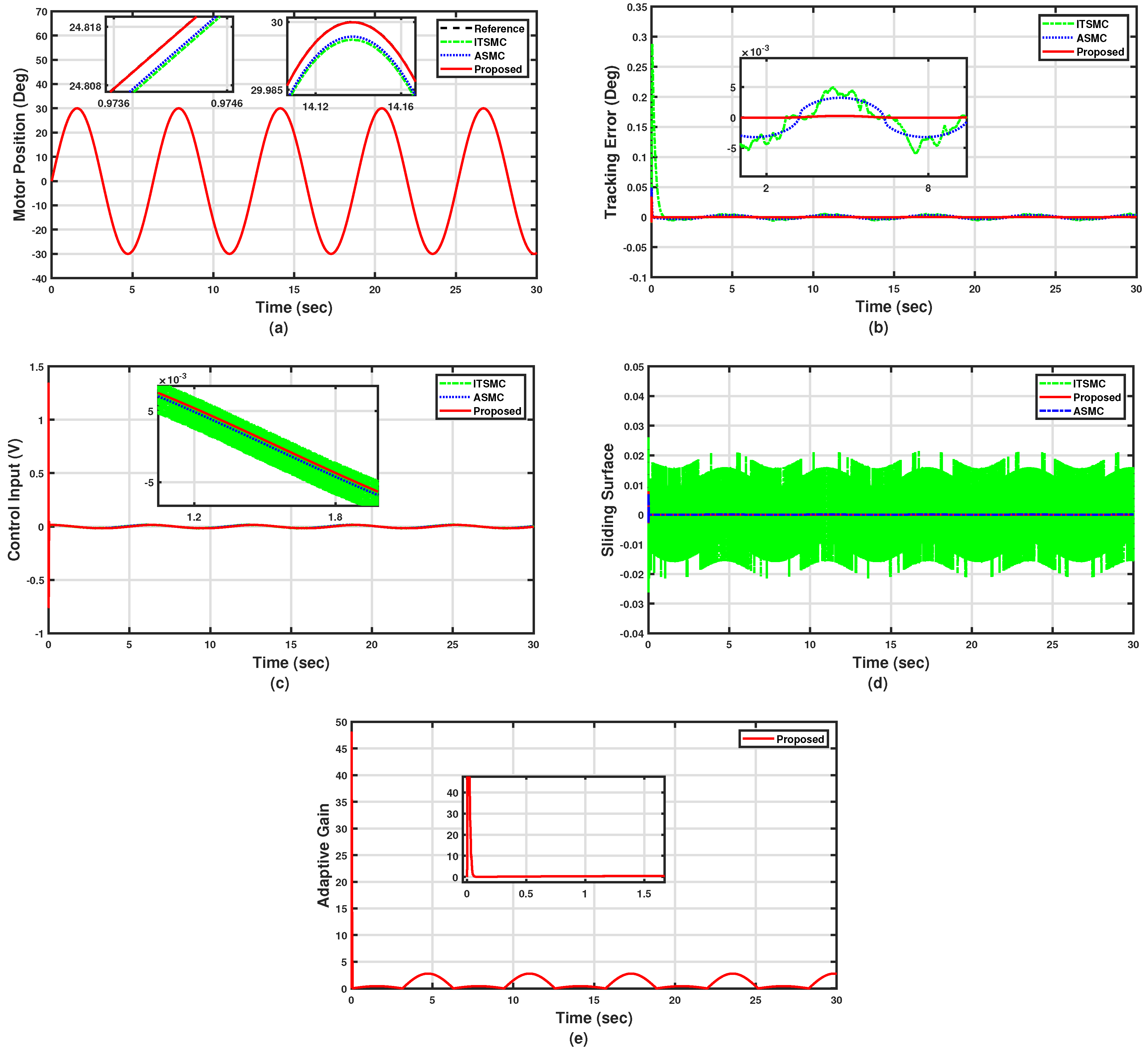
Case 2: Under the situation of a payload variation, the simulation results with dual sinusoidal reference defined by in Figure 3. It can be seen from Figure 3a,b that the proposed PAFTSMC also has better position tracking with less tracking error compared to the ITSMC and ASMC. Moreover, Figure 3c,d show that the high performance of the PAFTSMC is verified from the control input and sliding surface, which clearly indicates that the PAFTSMC has less chattering compared to other comparative controllers, even with the hard reference signal. Furthermore, the quantitative analysis of Case 2 is presented in Table 2 between the proposed PAFTSMC and comparative controllers under the dual sinusoidal reference. This analysis illustrates that the PAFTSMC has less tracking error with RMS = 0.00056 deg and MAX = 0.0314 deg. On the other hand, the first comparative ITSMC scheme has RMS = 0.0218 deg and MAX = 0.3401 deg. Moreover, the second comparative controller ASMC has RMS = 0.0037 deg and MAX = 0.0753.
The proposed adaptive gain for Case 2 is presented in Figure 3e, which initially provides high gains when the servo system states are far from the vicinity of the sliding surface, decreasing to small gains when the states are near the origin, as happened in Case 1 as well.
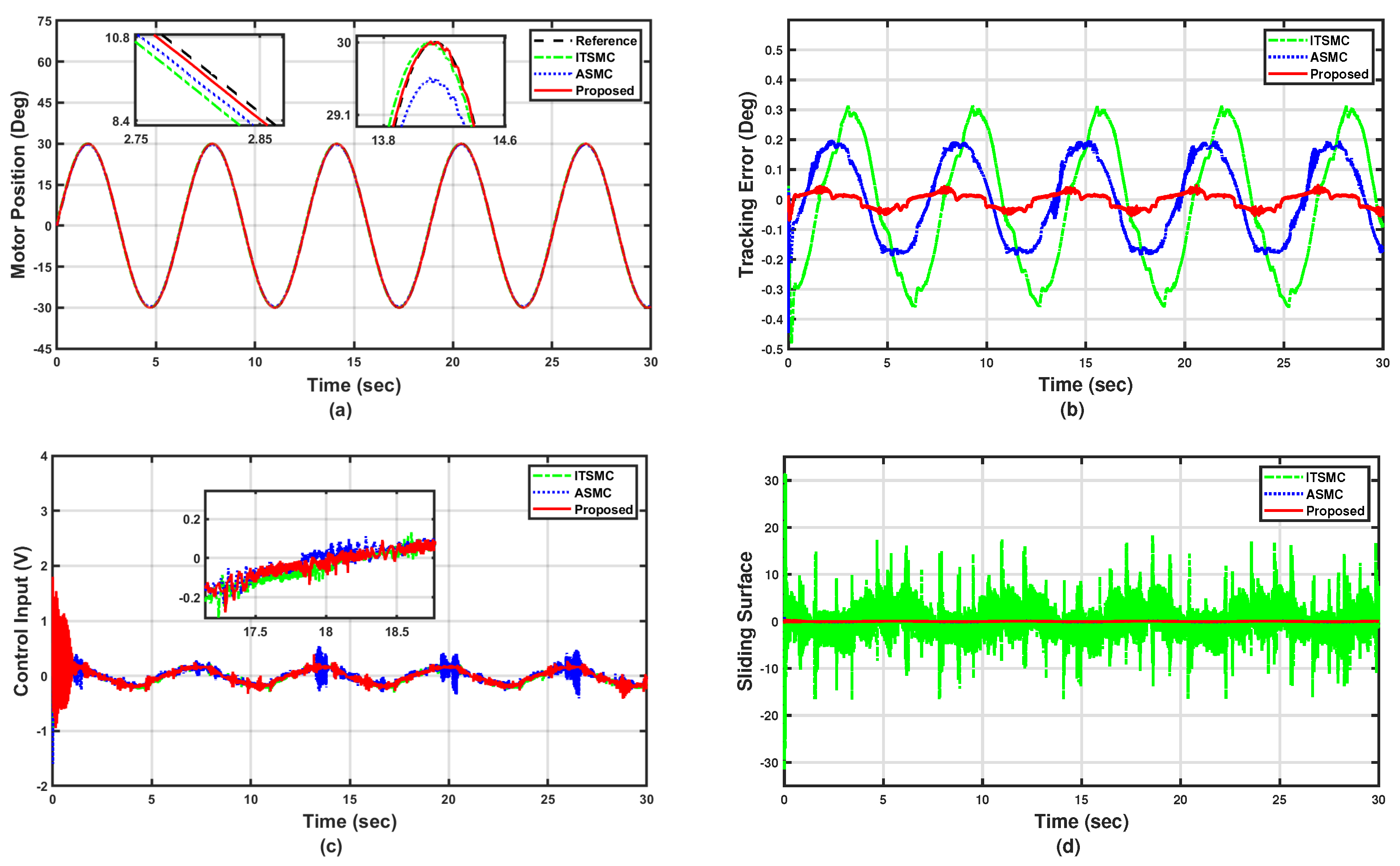
Case 3: Under the situation of an external disturbance, the simulation results of Case 3 are demonstrated in Figure 4 using as the desired reference considering the external disturbance assumed by acting on the servo motor. In the presence of external disturbance, our proposed controller still has better tracking performance, as shown in Figure 4a,b. However, in this situation, the performance of the comparative controllers, ITSMC and ASMC, decreased from the previous case in Case 1. Moreover, the control input and sliding surface in Figure 4c,d obviously show that PAFTSMC has less control chattering, the same as in Case 1, but the chattering of the comparative controllers is increased. Furthermore, as we discussed earlier, the proposed adaptive law increases the initial gain by increasing disturbances, and that can verified by Figure 4e, in which the proposed adaptive law increased the value of switching gain initially from the previous cases to compensate for the external disturbance. Then, in the steady state, the proposed adaptive law varies by a small value. The quantitative comparisons presented in Table 2 show that the proposed controller has the smallest tracking error by having RMS = 0.00048 deg and MAX = 0.0253 deg, while the ITSMC and ASMC both have larger tracking errors of RMS = 0.0230 and MAX = 0.3022, and RMS = 0.0053 and MAX = 0.0703, respectively.
Figure 2.
Simulation results with a sine reference and full load (Case 1).

Figure 3.
Simulation results with a dual sine reference and full load (Case 2).

Table 2.
Simulation error analysis.
| Cases | Index | Proposed | ITSMC | ASMC |
|---|---|---|---|---|
| Case 1 | RMS () | 0.00045 | 0.0183 | 0.0028 |
| MAX () | 0.0237 | 0.2889 | 0.0653 | |
| Case 2 | RMS () | 0.00056 | 0.0218 | 0.0037 |
| MAX () | 0.0314 | 0.3401 | 0.0753 | |
| Case 3 | RMS () | 0.00048 | 0.0230 | 0.0053 |
| MAX () | 0.0253 | 0.3022 | 0.0703 |
From Case 1 to Case 3, we have been concerned with most practical cases that exist in any mechanical and electrical system; thus, the proposed algorithm can be extended to different systems, such as different constructive types of engines.
Figure 4.
Simulation results with a sine reference and under external disturbance (Case 3).

4.2. Experimental Results Analysis
4.2.1. Experimental Setup
For experimental verification, the proposed PAFTSMC is tested on a real Industrial Emulator Servo Motor hardware system as shown in Figure 5. In this hardware, there are many parts, such as a servo motor system, an educational control product (ECP) board, a high-resolution encoder, and sensors. The servo motor system consists of a drive disk with four brass weights, a speed reducer, and a brushless DC servo motor. In the experimental setup, the electrical specifications of the servo motor have the minimum sampling time of servo-loop closure with 0.884 ms. Owing to the amplifier input voltage scaling, the range of the output voltage signal produced by the servo system is ±5 volts and is supplied to the motor drive via a digital–analog converter (DAC). In addition, this servo features a four-pole, three-phase star-wound brushless with Hall effect commutation. For more details, the electric characteristics of the electric motor can be found in [39]. Furthermore, the driving motor rotates the drive disk that is connected to the speed reduction component via a timing belt. To produce varying inertia of the drive disk, we can calibrate different brass weights. In addition, the ECP board consists of a DSP microprocessor and two 16-b DACs that convert the digital signal from the control computer to an analog signal and send it to the servo motor system.
4.2.2. Robustness Verification on Brushless DC Servo Motor
In this part, we conduct several experiments on the DC servo motor under different conditions and reference signals to determine the robustness and effectiveness of the PAFTSMC.
Case 1: The first case is carried out by using sinusoidal reference signal with a load variation. There are four loads that can be adjusted on the drive disk. To verify the robustness of the PAFTSMC under load variation, in Case 1, two loads are adjusted on the disk drive. As shown in Figure 6, its subplots show the tracking of position, error of the position, control input, and sliding surface, which are considered for discussion and comparison. Firstly, the PAFTSMC precisely tracks the desired reference signal, as can be seen in the zoomed sub-graph, compared to the ITSMC and ASMC. Secondly, the PAFTSMC has the smallest position tracking error and fast convergence to zero.
Finally, the proposed controller has the least chattering in control input and sliding surface as compared to other comparative controllers. Moreover, Table 3 presents the quantitative analysis in terms of RMS and MAX of the proposed controller, as well as comparative controllers. Table 3 indicates that the tracking error of PAFTSMC is smallest with RMS = 0.0234 deg and MAX = 0.0461 deg compared to the ITSMC, which has RMS = 0.2179 deg and MAX = 0.3143 deg, and the ASMC, which has RMS = 0.1355 deg and MAX = 0.1991 deg.
Case 2: The second case shown in Figure 7 uses the same desired reference and other situations of uncertainties. Here, the load on the disk drive is increased by attaching four brass weights on it. From Figure 7a, the tracking performance of the PAFTSMC is still better than the ITSMC and ASMC. As shown in Figure 7b, the tracking error of the proposed PAFTSMC is less and converges fast to zero.
From Figure 7c,d, the magnitude of control input is increased in this case due to a large load variation for all controllers as compared to the previous case, but the proposed controller has less chattering in the control input and sliding surface compared to others. In addition, Case 2 of Table 3 shows that the PAFTSMC has the smallest error in this case, like in the previous case with RMS = 0.0362 deg and MAX = 0.0459 deg compared to the ITSMC, which has RMS = 0.2915 deg and MAX = 0.4652 deg, and the ASMC, which has RMS = 0.1610 deg and MAX = 0.2402 deg.
Figure 6.
Experimental results with sine reference and half load on the disk drive.

Table 3.
Experimental error analysis.
| Cases | Index | Proposed | ITSMC | ASMC |
|---|---|---|---|---|
| Case 1 | RMS () | 0.0234 | 0.2179 | 0.1355 |
| MAX () | 0.0461 | 0.3143 | 0.1991 | |
| Case 2 | RMS () | 0.0362 | 0.2915 | 0.1610 |
| MAX () | 0.0459 | 0.4652 | 0.2402 | |
| Case 3 | RMS () | 0.0694 | 0.3396 | 0.1763 |
| MAX () | 0.1967 | 0.5336 | 0.3035 |
Case 3: In Figure 8, the responses of the servo motor in terms of tracking are evaluated by using a dual sines reference command. Here, by considering uncertainties and a full load situation, the DC servo motor is required to track the desired dual sinusoidal signals as defined by . As shown in the subplots of Figure 8, the magnitude of errors for all controllers increased because of the different desired reference commands and full load. However, still, our proposed PAFTSMC achieves better position tracking compared to the ITSMC and ASMC approaches.
Moreover, the PAFTSMC attains the smallest tracking error and fastest convergence to zero, and the best chattering reduction in the control effort and sliding surface. Furthermore, quantitative analysis for case 3 in Table 3 also demonstrates that the PAFTSMC has the best tracking performance with the smallest error with RMS = 0.0694 deg and MAX = 0.1967 deg compared to the ITSMC, which has RMS = 0.3396 deg and MAX = 0.5336 deg,, and the ASMC, which has RMS = 0.1763 deg and MAX = 0.3035 deg, respectively.
Figure 8e illustrates the performance of the proposed adaptive gain on the hardware experiment. The adaptive gain increases in the reaching phase when system states are far from the sliding surface and then decreases to a small value during the sliding phase. Moreover, the proposed adaptive gain is two-way adaptive. This means that the adaptive gain varies according to the disturbance change. When disturbances increase on the servo system, the proposed adaptive gain provides more gain. Otherwise, the gain comes to zero in the case of no disturbance. Therefore, the proposed two-way adaptive gain overcomes the problems of monotonically increasing gain, as in overestimation, and reduces the chattering in sliding mode and control signals.
Figure 7.
Experimental results with sine reference and full load on the disk drive.

Figure 8.
Experimental results with dual sine reference and full load on the disk drive.

To sum up the results above, the switching gain in the proposed control algorithm is updated by adaptive law in (14), which provides high gain initially for faster convergence of system states to corresponding desired references. In other words, the large adaptive gain can speed up the convergence of the tracking error to zero and compensate for the large tracking error at the beginning time in the transient region or reaching phase. Therefore, there is a trade-off between faster convergence and large control input at the transient region. However, the limitation of control input for the experimental platform system is ±5 volts, and the maximum control input produced by the proposed algorithm is under ±2 volts for all simulation and experimental tests conducted in the paper. Furthermore, not only are chattering reduction and gain overestimation avoidance guaranteed but there is also no need for the information of the disturbance upper bound. Under the proposed adaptive law (14), we can adjust the maximum value of switching gain by using constants of , r, , and .
5. Conclusions
In this article, a practical adaptive fast terminal sliding mode control (PAFTSMC) has been proposed for the position control of the servo motor system in the presence of uncertainties, nonlinearities, external disturbances, and load variations. By using a smooth tangent hyperbolic function, a finite-time terminal sliding surface had been designed not only to reduce the chattering but also to avoid the singularity issues of traditional terminal sliding mode control strategies. Moreover, with the help of the proposed bidirectional adaptive law, the overestimation problems of monotonically increasing gain have been solved for further chattering reduction. Furthermore, the finite-time stability of the closed-loop system has been proved based on the Lyapunov theorem. Finally, the simulation studies and experimental tests demonstrated the advantages of the proposed controller in terms of strong robustness, better tracking, and significantly reduced chattering as compared to existing control algorithms. In future work, we will extend our proposed control to other types of actuators with matched and unmatched uncertainties. Furthermore, for more practicality, we will investigate the application efficiency of the proposed control to more real-world systems, such as several types of engines.
Author Contributions
Conceptualization, K.A., Z.C., K.R. and Z.M.; methodology, K.A., Z.C. and K.R.; software, K.A.; validation, K.A., K.R. and Z.C.; formal analysis, K.A. and K.R.; investigation, K.A., Z.C. and K.R.; resources, Z.C. and Z.M.; writing—original draft preparation, K.A.; writing—review and editing, K.R., Z.C. and Z.M.; visualization, K.A., K.R. and Z.C.; supervision, Z.C. and Z.M.; project administration, Z.C. All authors have read and agreed to the published version of the manuscript.
Funding
This work was supported in part by the Australian Research Council Discovery Project under Grant DP190101557.
Informed Consent Statement
Not applicable.
Data Availability Statement
Data are contained within the article.
Conflicts of Interest
The authors declare no conflict of interest.
References
- Wang, B.; Iwasaki, M.; Yu, J. Command filtered adaptive backstepping control for dual-motor servo systems with torque disturbance and uncertainties. IEEE Trans. Ind. Electron. 2022, 69, 1773–1781. [Google Scholar] [CrossRef]
- Kim, S. Moment of inertia and friction torque coefficient identification in a servo drive system. IEEE Trans. Ind. Electron. 2019, 66, 60–70. [Google Scholar] [CrossRef]
- Zhu, W.L.; Yang, X.; Duan, F.; Zhu, Z.; Ju, B.F. Design and adaptive terminal sliding mode control of a fast tool servo system for diamond machining of freeform surfaces. IEEE Trans. Ind. Electron. 2019, 66, 4912–4922. [Google Scholar] [CrossRef]
- Ding, R.; Ding, C.; Xu, Y.; Liu, W.; Yang, X. Neural network-based robust integral error sign control for servo motor systems with enhanced disturbance rejection performance. ISA Trans. 2022, 129, 580–591. [Google Scholar] [CrossRef]
- Yao, J.; Deng, W. Active disturbance rejection adaptive control of hydraulic servo systems. IEEE Trans. Ind. Electron. 2017, 66, 8023–8032. [Google Scholar] [CrossRef]
- Zhong, G.; Shao, Z.; Deng, H.; Ren, J. Precise position synchronous control for multi-axis servo systems. IEEE Trans. Ind. Electron. 2017, 64, 3707–3717. [Google Scholar] [CrossRef]
- Jasim, M.H. Tuning of a PID controller by bacterial foraging algorithm for position control of DC servo motor. Eng. Technol. J. 2018, 36, 287–294. [Google Scholar] [CrossRef]
- Shi, D.; Xue, J.; Zhao, L.; Wang, J.; Huang, Y. Event-triggered active disturbance rejection control of DC torque motors. IEEE/ASME Trans. Mechatron. 2017, 22, 2277–2287. [Google Scholar] [CrossRef]
- Ding, S.; Mei, K.; Yu, X. Adaptive second-order sliding mode control: A Lyapunov approach. IEEE Trans. Autom. Control 2022, 67, 5392–53997. [Google Scholar] [CrossRef]
- Cheng, Y.; Ren, X.; Zheng, D.; Li, L. Non-linear bandwidth extended-state-observer based non-smooth funnel control for motor-drive servo systems. IEEE Trans. Ind. Electron. 2022, 69, 6215–6224. [Google Scholar] [CrossRef]
- Dong, H.; Yang, X.; Gao, H.; Yu, X. Practical terminal sliding-mode control and its applications in servo systems. IEEE Trans. Ind. Electron. 2023, 70, 752–761. [Google Scholar] [CrossRef]
- Zhang, J.; Gao, W.; Guo, Q. Extended State Observer-Based Sliding Mode Control Design of Two-DOF Lower Limb Exoskeleton. Actuators 2023, 12, 402. [Google Scholar] [CrossRef]
- Ma, Z.; Huang, P.; Kuang, Z. Fuzzy approximate learning-based sliding mode control for deploying tethered space robot. IEEE Trans. Fuzzy Syst. 2021, 29, 2739–2749. [Google Scholar] [CrossRef]
- Chaturvedi, S.; Kachhwaha, M.; Fulwani, D. Robust Integral Sliding Mode Control for Transient Voltage Support from Bi-Directional Converter Based Active Filters in Microgrids. IEEE J. Emerg. Sel. Top. Ind. Electron. 2003, 4, 995–1005. [Google Scholar] [CrossRef]
- Veysi, M.; Aghaei, J.; Soltanpour, M.R.; Shasadeghi, M.; Bahrani, B.; Ryan, D.J. Robust, accurate, and fast decentralized power sharing mechanism for isolated DC microgrid using droop-based sliding-mode control. IEEE Trans. Smart Grid 2022, 13, 4160–4173. [Google Scholar] [CrossRef]
- Feng, Z.; Liang, W.; Ling, J.; Xiao, X.; Tan, K.K.; Lee, T.H. Precision force tracking control of a surgical device interacting with a deformable membrane. IEEE/ASME Trans. Mechatron. 2022, 27, 5327–5338. [Google Scholar] [CrossRef]
- Feng, Z.; Liang, W.; Ling, J.; Xiao, X.; Tan, K.K.; Lee, T.H. Adaptive robust impedance control for an ear surgical device with soft interaction. IEEE/ASME Trans. Mechatron. 2022, 27, 1784–1795. [Google Scholar] [CrossRef]
- Mofid, O.; Mobayen, S. Adaptive sliding mode control for finite-time stability of quad-rotor UAVs with parametric uncertainties. ISA Trans. 2018, 72, 1–14. [Google Scholar] [CrossRef]
- Zhang, B.; Nie, K.; Chen, X.; Mao, Y. Development of sliding mode controller based on internal model controller for higher precision electro-optical tracking system. Actuators 2022, 11, 16. [Google Scholar] [CrossRef]
- Zhihong, M.; Yu, X.H. Terminal sliding mode control of MIMO linear systems. IEEE Trans. Circuits Syst. I Fundam. Theory Appl. 1997, 44, 1065–1070. [Google Scholar] [CrossRef]
- Feng, Y.; Yu, X.; Man, Z. Non-singular terminal sliding mode control of rigid manipulators. Automatica 2002, 38, 2159–2167. [Google Scholar] [CrossRef]
- Ding, S.; Hou, Q.; Wang, H. Disturbance-observer-based second-order sliding mode controller for speed control of PMSM drives. IEEE Trans. Energy Convers. 2023, 38, 100–110. [Google Scholar] [CrossRef]
- Kommuri, S.K.; Rath, J.J.; Veluvolu, K.C. Sliding-mode-based observer–controller structure for fault-resilient control in DC servomotors. IEEE Trans. Ind. Electron. 2018, 65, 918–929. [Google Scholar] [CrossRef]
- Li, J.; Liu, X.; Xu, M.; Fang, Y. Continuous higher-order sliding mode control for a class of n-th order perturbed systems. IEEE Trans. Circuits Syst. II Express Briefs 2022, 69, 3179–3183. [Google Scholar] [CrossRef]
- Fei, J.; Wang, H.; Fang, Y. Novel neural network fractional-order sliding-mode control with application to active power filter. IEEE Trans. Syst. Man Cybern. Syst. 2022, 52, 3508–3518. [Google Scholar] [CrossRef]
- Çelik, D.; Ahmed, H.; Meral, M.E. Kalman filter-based super-twisting sliding mode control of shunt active power filter for electric vehicle charging station applications. IEEE Trans. Power Del. 2023, 38, 1097–1107. [Google Scholar] [CrossRef]
- Junejo, A.K.; Xu, W.; Mu, C.; Ismail, M.M.; Liu, Y. Adaptive speed control of PMSM drive system based a new sliding-mode reaching law. IEEE Trans. Power Electron. 2020, 35, 12110–12121. [Google Scholar] [CrossRef]
- Tian, D.; Xu, R.; Sariyildiz, E.; Gao, H. An adaptive switching-gain sliding-mode-assisted disturbance observer for high-precision servo control. IEEE Trans. Ind. Electron. 2022, 69, 1762–1772. [Google Scholar] [CrossRef]
- Piñón, A.; Favela-Contreras, A.; Beltran-Carbajal, F.; Lozoya, C.; Dieck-Assad, G. Novel Strategy of Adaptive Predictive Control Based on a MIMO-ARX Model. Actuators 2022, 11, 21. [Google Scholar] [CrossRef]
- Armghan, H.; Yang, M.; Ali, N.; Armghan, A.; Alanazi, A. Quick reaching law based global terminal sliding mode control for wind/hydrogen/battery DC microgrid. Appl. Energy 2022, 316, 119050. [Google Scholar] [CrossRef]
- Zheng, J.; Wang, H.; Man, Z.; Jin, J.; Fu, M. Robust motion control of a linear motor positioner using fast nonsingular terminal sliding mode. IEEE/ASME Trans. Mechatron. 2015, 20, 1743–1752. [Google Scholar] [CrossRef]
- Xu, D.; Ding, B.; Jiang, B.; Yang, W.; Shi, P. Nonsingular fast terminal sliding mode control for permanent magnet linear synchronous motor via high-order super-twisting observer. IEEE/ASME Trans. Mechatron. 2022, 27, 1651–1659. [Google Scholar] [CrossRef]
- Feng, Y.; Zhou, M.; Han, Q.L.; Han, F.; Cao, Z.; Ding, S. Integral-type sliding-mode control for a class of mechatronic systems with gain adaptation. IEEE Trans. Ind. Inform. 2020, 16, 5357–5368. [Google Scholar] [CrossRef]
- Nguyen, T.H.; Nguyen, T.T.; Nguyen, V.Q.; Le, K.M.; Tran, H.N.; Jeon, J.W. An adaptive sliding-mode controller with a modified reduced-order proportional integral observer for speed regulation of a permanent magnet synchronous motor. IEEE Trans. Ind. Electron. 2022, 69, 7181–7191. [Google Scholar] [CrossRef]
- Li, P.; Zhu, G. Robust internal model control of servo motor based on sliding mode control approach. ISA Trans. 2019, 93, 199–208. [Google Scholar] [CrossRef]
- Yu, X.; Zhihong, M. Fast terminal sliding-mode control design for nonlinear dynamical systems. IEEE Trans. Circuits Syst. I Fundam. Theory Appl. 2002, 49, 261–264. [Google Scholar]
- Rsetam, K.; Cao, Z.; Man, Z. Design of robust terminal sliding mode control for underactuated flexible joint robot. IEEE Trans. Syst. Man Cybern. Syst. 2022, 52, 4272–4285. [Google Scholar] [CrossRef]
- Chalanga, A.; Kamal, S.; Bandyopadhyay, B. A new algorithm for continuous sliding mode control with implementation to industrial emulator setup. IEEE/ASME Trans. Mechatron. 2015, 20, 2194–2204. [Google Scholar] [CrossRef]
- Installation and User Manual of ECP Model 220 for Use With MATLAB-R14 Using Real Time Windows Target (RTWT); Educational Control Products: Woodland Hills, CA, USA, 2004.
Figure 1.
Block diagram of the PAFTSMC for the servo motor system.
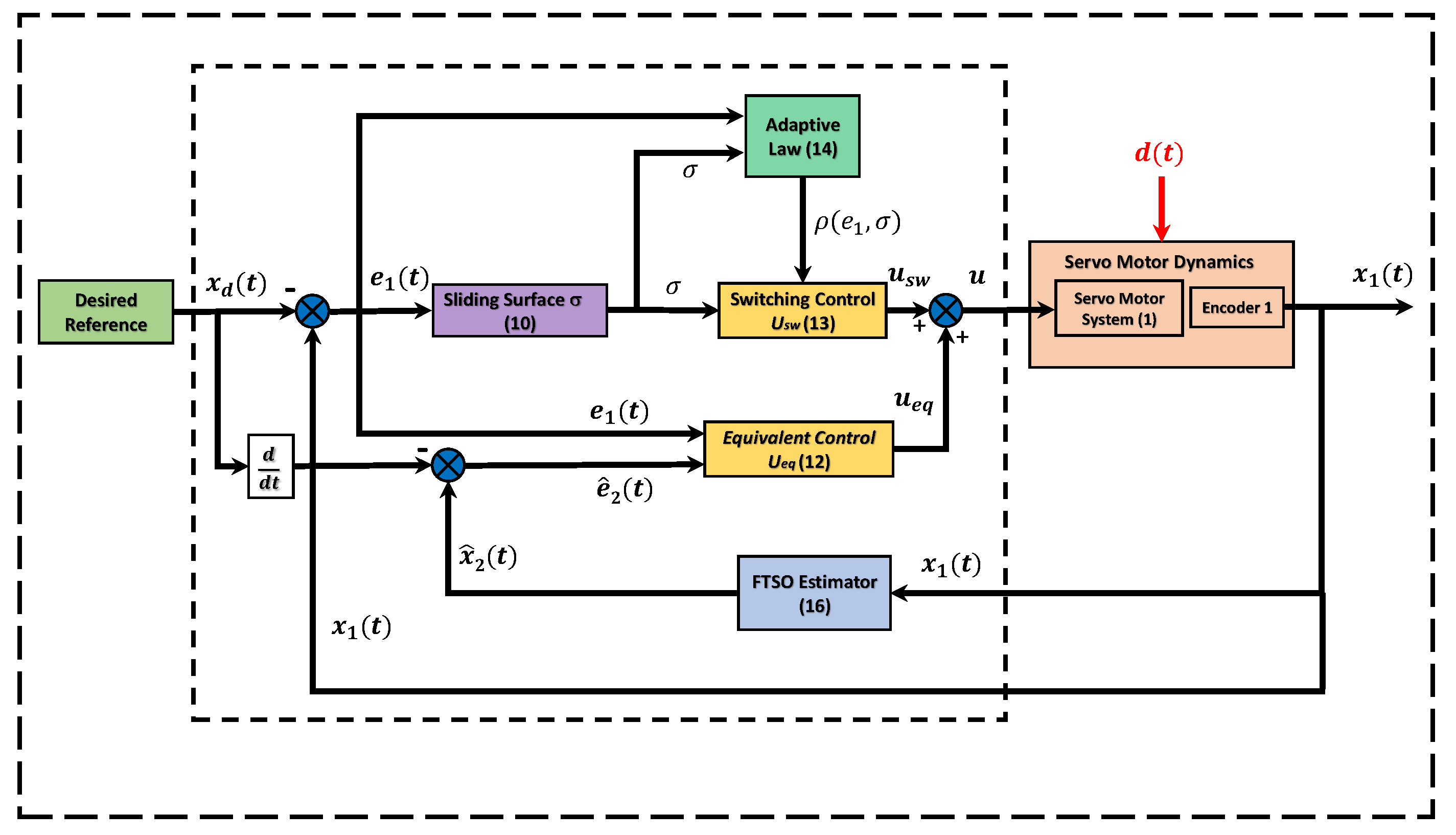
Figure 5.
Experimental platform.
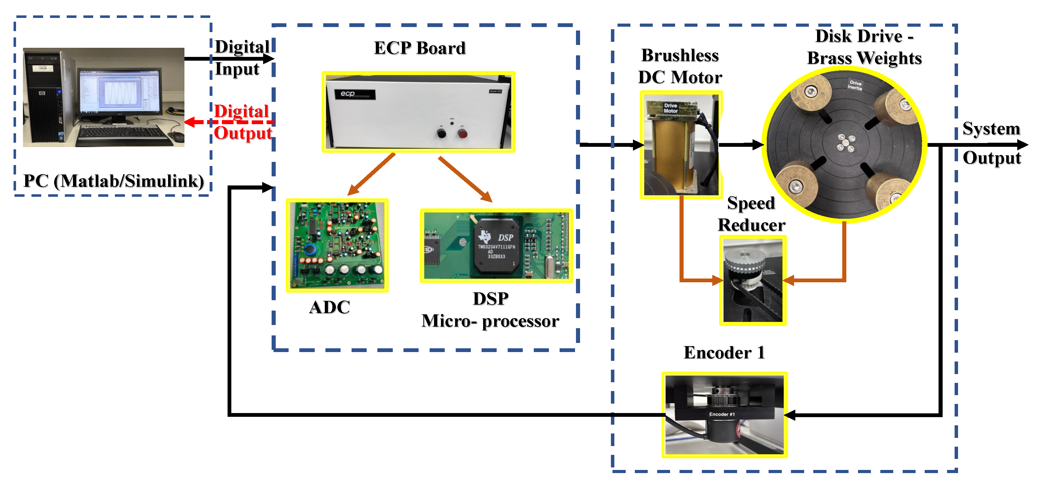
Table 1.
Control parameters.
| Controller | Controller Parameter |
|---|---|
| Proposed | = 45; = 25; = 0.071; = 0.93; r = 25; = ; = 0.051; = ; |
| = 0.93; and = 100. | |
| ITSMC | = 100; = 45; = 0.79; = 0.89; and = 20. |
| ASMC | = 45; k = 23; = ; and = 5. |
Disclaimer/Publisher’s Note: The statements, opinions and data contained in all publications are solely those of the individual author(s) and contributor(s) and not of MDPI and/or the editor(s). MDPI and/or the editor(s) disclaim responsibility for any injury to people or property resulting from any ideas, methods, instructions or products referred to in the content. |
© 2023 by the authors. Licensee MDPI, Basel, Switzerland. This article is an open access article distributed under the terms and conditions of the Creative Commons Attribution (CC BY) license (https://creativecommons.org/licenses/by/4.0/).
Share and Cite
MDPI and ACS Style
Ali, K.; Cao, Z.; Rsetam, K.; Man, Z. Practical Adaptive Fast Terminal Sliding Mode Control for Servo Motors. Actuators 2023, 12, 433. https://doi.org/10.3390/act12120433
AMA Style
Ali K, Cao Z, Rsetam K, Man Z. Practical Adaptive Fast Terminal Sliding Mode Control for Servo Motors. Actuators. 2023; 12(12):433. https://doi.org/10.3390/act12120433
Chicago/Turabian StyleAli, Kamran, Zhenwei Cao, Kamal Rsetam, and Zhihong Man. 2023. "Practical Adaptive Fast Terminal Sliding Mode Control for Servo Motors" Actuators 12, no. 12: 433. https://doi.org/10.3390/act12120433
Note that from the first issue of 2016, this journal uses article numbers instead of page numbers. See further details here.