
Numerical Investigation of Effect of Structural Parameters on the Performance of a Combustion-Driven Sparkjet Actuator


College of Aerospace Science and Engineering, National University of Defense Technology, Changsha 410073, China
*
Author to whom correspondence should be addressed.
Actuators 2023, 12(6), 250; https://doi.org/10.3390/act12060250
Submission received: 3 April 2023
/
Revised: 4 June 2023
/
Accepted: 12 June 2023
/
Published: 15 June 2023
(This article belongs to the Section Miniaturized and Micro Actuators)
Abstract
:With the aim of increasing the momentum jet and obtaining better environmental adaptability, this study designs a new type of actuator combining a sparkjet actuator and a combustion-driven actuator. Numerical simulation shows that the combustion-driven sparkjet actuator has a higher velocity and mass rate compared to the sparkjet actuator when the length and orifice diameter are 6.5 mm and 1.3 mm, respectively, while the saturation work frequency is almost the same. A parameter study shows that as the volume increases, the pressure, orifice velocity, and mass rate of the combustion-driven sparkjet actuator increase. By contrast, the saturation work frequency decreases. Moreover, as the orifice diameter decreases, the orifice peak velocity, temperature, and pressure increase, whereas the mass flow rate and saturation work frequency decrease.
1. Introduction
Significant effort has recently been devoted to the development of actuation technologies for flow control [1,2,3,4]. Effective manipulation of the flow field can lead to considerable benefits for vehicle systems, including enhanced performance, maneuverability, payload, and range. Active flow control actuators can be categorized as fluidic, mechanical, and plasma [5]. Among them, fluidic actuators can be classified as pulsed jet or combustion-driven sparkjet actuators. Plasma actuators are mainly classified as dielectric-barrier discharge, DC, or spark discharge actuators.
Grossman et al. [6] first developed the plasma synthetic jet (also called pulsed plasma or sparkjet) actuator in 2003. The material is an insulating ceramic, with the anode and tip cathode located at the top and bottom of the actuator cavity, respectively. The jet velocity measured by experiments is about 100 m/s. Improving the cavity structure and materials of the actuator, Belinger et al. [7] enhanced the heat dissipation and thereby increased the operating frequency of the actuator to 500 Hz and the jet velocity to 250 m/s. The research team of the Air Force Engineering University [8,9,10] studied the influence of actuator structure, electrode position, discharge frequency, capacitor energy, outlet configuration, and other parameters by using zero-dimensional theoretical calculation, shadowgraphs, PIV, and other technical methods. Liu R B and Lin Q et al. [11] proposed an inflatable plasma synthetic jet actuator with a one-way valve to improve work frequency. Li J F and Zhang X B et al. [12] proposed an actuator that combines a piezoelectric oscillator and sparkjet discharge to improve the cavity suction recovery ability and increase the pressure of the actuator cavity through the regulation effect of the piezoelectric oscillator on cavity volume. Luo Z B and Wang L et al. [13,14] proposed an enhanced version of a two-electrode actuator by adding a high-voltage trigger electrode (as shown in Figure 1). This three-electrode actuator has a reduced break-down voltage and increased discharge energy and cavity volume. Preliminary experiments show that the maximum jet velocity of the actuator is more than 500 m/s. However, the plasma synthetic jet actuator has several problems, such as a low refill rate, limited saturation work frequency, and poor environmental adaptability [15], especially in high-altitude and supersonic rarefied flow field environments. Zhou Y et al. [16] numerically studied the performance of a two-electrode plasma synthetic jet actuator and found that the numerical results are in good agreement with the experiment. Moreover, the influence of orifice shapes on jet flow has been analyzed. Huang H X et al. [17] examined the transient interaction between a two-electrode plasma synthetic jet actuator and a supersonic compression ramp flow field. Narayanaswamy V et al. [18] conducted an experimental study of a pulsed-plasma jet actuator’s performance and found that the pulsed-plasma jet actuator creates a sufficiently strong flow perturbation that holds great promise as a supersonic flow actuator.
Based on small-scale combustion technology [19,20,21,22,23,24], Crittenden [25] proposed a new actuator powered by combustion. Figure 2 shows the schematic of the micro axisymmetric combustion driver. The burning blend with a low mass flow rate fills the driver and is ignited by ignition sources. The combustion driver generates a high-pressure burst and jet. The cycle restarts with a fresh blend refilling the actuator and replacing the burned gas. Crittenden [26], Rajendar [27] and Srinivasan [28] studied the effect of the fuel type, chamber volume, mixture ratio, chamber surface area, ignition source and exhaust orifice diameter on small-scale combustion with experiments and numerical simulations. Crittenden [29] showed that the actuator operating performance is not affected by rain, vibration, ice, or a particulate environment. Jee S. et al. [30] investigated this combustion driver via numerical and experimental methods and found that it can effectively improve the aerodynamic lift. However, the jet velocity of the combustion driver needs further enhancement.
To overcome the disadvantages of sparkjet actuators and combustion-driven actuators, we propose a combustion-driven sparkjet actuator, as illustrated in Figure 3. This actuator combines the advantages of sparkjet and combustion-driven actuators, improving the velocity and environmental adaptability. The effects of actuator length and orifice diameter on the performance are numerically investigated, and the underlying mechanisms are addressed.
2. Mathematical-Physical Model
2.1. Computational Model
The governing equations of the gas phase, including the continuity, momentum, chemical component transport, and the energy conservation equations, were solved using Fluent 15.
The solution methods and flux type are implicit formulation and RoeFDS, respectively. A second-order upwind method is employed for the spatial discretization, and a second-order implicit method is used for the unsteady formulation. The time step is 2 × 10⁻⁸ s, each with 60 maximum iterations. The SST K-ω turbulent model is employed for the viscous model during the simulation. The density and specific heat of blends are calculated using the compressible ideal gas law and mixing law, respectively. By using the mass weighted mixing law and kinetic theory, we calculate the thermal conductivity and viscosity of the mixture. Kinetic theory is also adopted to calculate the blend mass diffusivity. A piecewise polynomial fitting method is used to compute the specific heat of each species. The pressure outlet condition is specified with a fixed pressure of 1.013 × 10⁵ Pa at the outlet, and the natural convection heat transfer coefficient is set at 10 W/m2/K [5,31].
This study mainly examines the influence of actuator structural parameters on the performance; therefore, the premixed hydrogen/air equivalence ratio is 1.0. The detailed reaction mechanism involving 9 species and 19 reversible reactions [32] is used for modeling the combustion of hydrogen/air mixture. Meanwhile, the eddy dissipation conception (EDC) model [24] is adopted to solve the turbulence–chemistry interaction because of its advantage of incorporating the effect of finite rate kinetics on computing costs and including the turbulence’s effect on the reaction rate [33]. The energy deposition of the discharge is simulated by adding a source term in the energy equation [34]. The discharge zone is defined as a separate region in the calculation, as shown in Figure 4. The energy source term is added into the discharge zone and it is assumed that the energy is uniformly distributed over the discharge duration and discharge region. The source term and discharge duration are 7 × 10¹⁰ W/m3 and 16 μs, respectively. Figure 4 shows the numerical model of the actuator. The geometry is modelled as a 2D axi-symmetric model due to the axial symmetry of the actuator [16]. In this study, we assume that the premixed blends in the actuator have been filled, the valve has been closed, and the arc discharge is struck inside the chamber.
2.2. Mesh Independency Test and Model Validation
To verify the accuracy of the numerical model of combustion, we compare the numerical results with the experimental data in the literature [23]. At this time, the combustion model parameters and the boundary conditions of numerical model are consistent with those in the literature. Table 1 shows that the numerical results have good agreement with the experimental data. Therefore, the numerical model is reliable.
Moreover, the numerical results and experimental data [16] of the sparkjet actuator under the same conditions are compared. Figure 5 shows that the numerical and experimental results are in good agreement in terms of the precursor shock wave and front jet. These data indicate that the established sparkjet actuator computational model is sufficiently accurate to capture fluid characteristics.
Grid independence is verified with a 2D model of the combustion-driven sparkjet actuators under four mesh intervals: 2 × 10⁻⁵, 2.7 × 10⁻⁵, 3.3 × 10⁻⁵, and 4 × 10⁻⁵ m. The length and the orifice diameter of the actuators are 6.5 mm and 1.3 mm, respectively; the heat transfer coefficient is 10 W/m2/K. Figure 6 shows that the velocity, pressure and temperature variation trends at the outlet are similar as the grid size increases from 2 × 10⁻⁵ to 3.3 × 10⁻⁵ m. Thus, the mesh size of 3.3 × 10⁻⁵ m is used in our final computation to maintain high accuracy and save computational time.
3. Results and Discussion
3.1. Influence of Actuator Length
The effects of different lengths and orifice diameters on the working performance of the actuators can be examined by using the parameter dimensions in Table 2. The diameter and length of the actuator inlet are 2.5 mm and 1 mm, respectively. The outlet length and inner diameter of the actuator are 1 mm and 10 mm, respectively. Among them, Case 1 is the sparkjet actuator, and Cases 2–6 are the combustion-driven sparkjet actuator.
To ensure sufficient working medium in the cavity and optimize the working performance of the actuator, Wang L et al. [34] defined the maximum working frequency that can fully refill the actuator cavity as the saturation work frequency. When the discharge frequency exceeds saturation work frequency, it can cause misfire due to the actuator cavity not being fully backfilled. In addition, in order to evaluate the quick response ability of the actuator, the time when the jet momentum of the actuator reaches its maximum value is defined as the peak time tpeak of the jet. A shorter peak time means a faster response of the actuator.
The jet momentum can be expressed as:
where τ is the jet duration, is the jet flow rate, and uj is the jet instantaneous velocity.
As shown in Figure 7, the peak velocity of the combustion driver is 1392 m/s, which is considerably larger than that of the sparkjet actuator, at 594 m/s. The saturation work frequency is almost the same, and the heat release of the combustion improves the pressure and temperature in the combustion-driven sparkjet actuator. As a result, the outlet jet velocity of the combustion-driven sparkjet actuator is much higher than that of the sparkjet actuator. In addition, as the volume increases, the pressure and mass rate of combustion driver also increase while the saturation work frequency decreases.
Figure 8 shows that, at 16 µs from the discharge triggering, the peak temperature of the combustion-driven sparkjet actuator is 2300 K, higher than that of the sparkjet actuator at 2000 K. Moreover, the temperature near the wall area is slightly higher, which means that the mixture begins to react. At 100 µs, the high-temperature gas in the sparkjet actuator moves towards the outlet, while the temperature in the combustion-driven sparkjet actuator increases rapidly due to the mixture reaction. The flame front is substantially wrinkled, and the peak temperatures of the combustion-driven sparkjet actuator when the actuator volume equals 0.25, 0.5, and 1 cm3 are 3249 K, 3116 K, and 3180 K, respectively. With the increase in volume, the percentage of the unburned mixture increases. The reason for this is that the chemical reaction time increases as the volume and mixture mass becomes larger, meaning the flame front takes more time to propagate to the chamber walls, scaling closely with chamber length. At 200 µs, the area of the high-temperature zone raises; the peak temperatures in the 0.5 and 1 cm3 actuators rise to 3200 K and 3300 K, respectively, while that in the 0.25 cm3 actuator decreases to 3000 K. The reason for this is that the mixture mass increases as the combustion chamber size increases, thereby releasing more heat from combustion. Moreover, the ratio of volume to surface area also decreases substantially as the volume decreases, and the heat loss is expected to increase. At 350 µs, the temperature in the actuator begins to decline as time passes. A larger volume increases the chemical reaction time, and thus the actuator saturation work frequency rises correspondingly. Additionally, the volume increase leads to increased combustion heat and actuator temperature.
Figure 9 shows the OH mass fraction of actuators at various delay times. At 16 µs, a small amount of OH components are produced near the wall area, indicating that the mixture begins to react. When time equals 100 µs, the magnitude of the OH mass fraction rises quickly, indicating an increase in combustion intensity. Moreover, part of areas in the 1 cm3 actuator does not generate the OH components, which means part of the mixture in the driver undergoes no chemical reaction. At 200 µs, the magnitude of OH components continues to increase. At 350 µs, the amount of OH components keeps raising, whereas the magnitude of the OH mass fraction declines, indicating a drop in combustion intensity. At 900 µs, the OH components have a low magnitude, indicating that the chemical reaction is nearly complete. The OH components concentration decreases as the chamber volume decreases. This is because the volume to surface area ratio decreases as the volume decreases, which results in higher heat loss and lower reaction intensity.
Figure 10 shows that at 16 µs, the pressure in the sparkjet actuator reaches its peak value, while that in the combustion-driven sparkjet actuator is slightly higher. At 100 µs, the pressure in the sparkjet actuator decreases, while that in the combustion-driven sparkjet actuator rises. With the increase in volume, the time that the pressure takes to reach its peak value also lengthens accordingly. The pressure in the combustion-driven sparkjet actuator is clearly larger than that in the sparkjet actuator due to the heat release caused by combustion. Most mixtures are burnt within about 350 µs, 200 µs and 200 µs for the 1, 0.5, and 0.25 cm3 combustion-driven sparkjet actuators, as shown in Figure 8 and Figure 9, and the combustion-driven sparkjet actuator reaches its peak value at a corresponding time and then decreases gradually.
3.2. Influence of Actuator Orifice Diameter
Figure 11 shows the work performance of actuators with various orifice diameters with a fixed value of combustion driver length. Clearly, the outlet peak velocity, temperature, and pressure increase as the orifice diameter declines. By contrast, the mass flow rate and saturation work frequency also decrease. This is because the small orifice diameter enhances the blocking effect of the boundary layer thickness on the airflow at outlet. Jet momentum is an important parameter of work performance, as a function of the speed and fluid mass. Actuators with a large orifice diameter have a low outlet peak velocity but a higher fluid mass and saturation work frequency.
Figure 12 and Figure 13 illustrate the temperature contours and OH mass fraction on the cross section of three combustion drivers with various orifice diameters. At 16 µs after the start of the discharge, the combustion driver has similar temperature distributions. At 140 µs, the highest temperature and OH mass fraction in Case 3 are 3200 K and 0.0316, respectively. As the orifice diameter increases to 2 mm, the highest temperature and OH mass fraction in the combustion driver decrease to 3080 K and 0.029, respectively. As the orifice diameter further increases, the highest temperature and OH mass fraction in the combustion driver decrease to 2880 K and 0.025, respectively. At 200 µs, the maximum temperature and OH mass fraction of the actuator with a 1.3 mm orifice diameter increase to approximately 3260 K and 0.033, respectively, while those of the actuator with a 2 mm orifice diameter are 3097 K and 0.029, separately. As the orifice diameter increases to 2.8 mm, the maximum temperature and OH mass fraction decrease to 2790 K and 0.025, respectively. After 350 µs, the temperature and reaction intensity gradually decrease. Clearly, the temperature and chemical reaction intensity decrease as the orifice diameter increases.
In order to further investigate the combustion features of three combustion drivers with various orifice diameters, Figure 14 shows the mass of the hydrogen leakage at t = 0.04–0.07 ms. The mixture spurts out from the actuator due to the heat release caused by combustion and energy deposition. Part of the mixture spurts out from the actuator before it burns on account of the limited combustion rate, which leads to fuel loss. The mass of the hydrogen leakage increases with the increase in orifice diameter, leading to heat release and temperature decline. The actuator performance degrades with the increase in the mass of the hydrogen leakage. Hence, the orifice diameter must be selected reasonably under different work requirements.
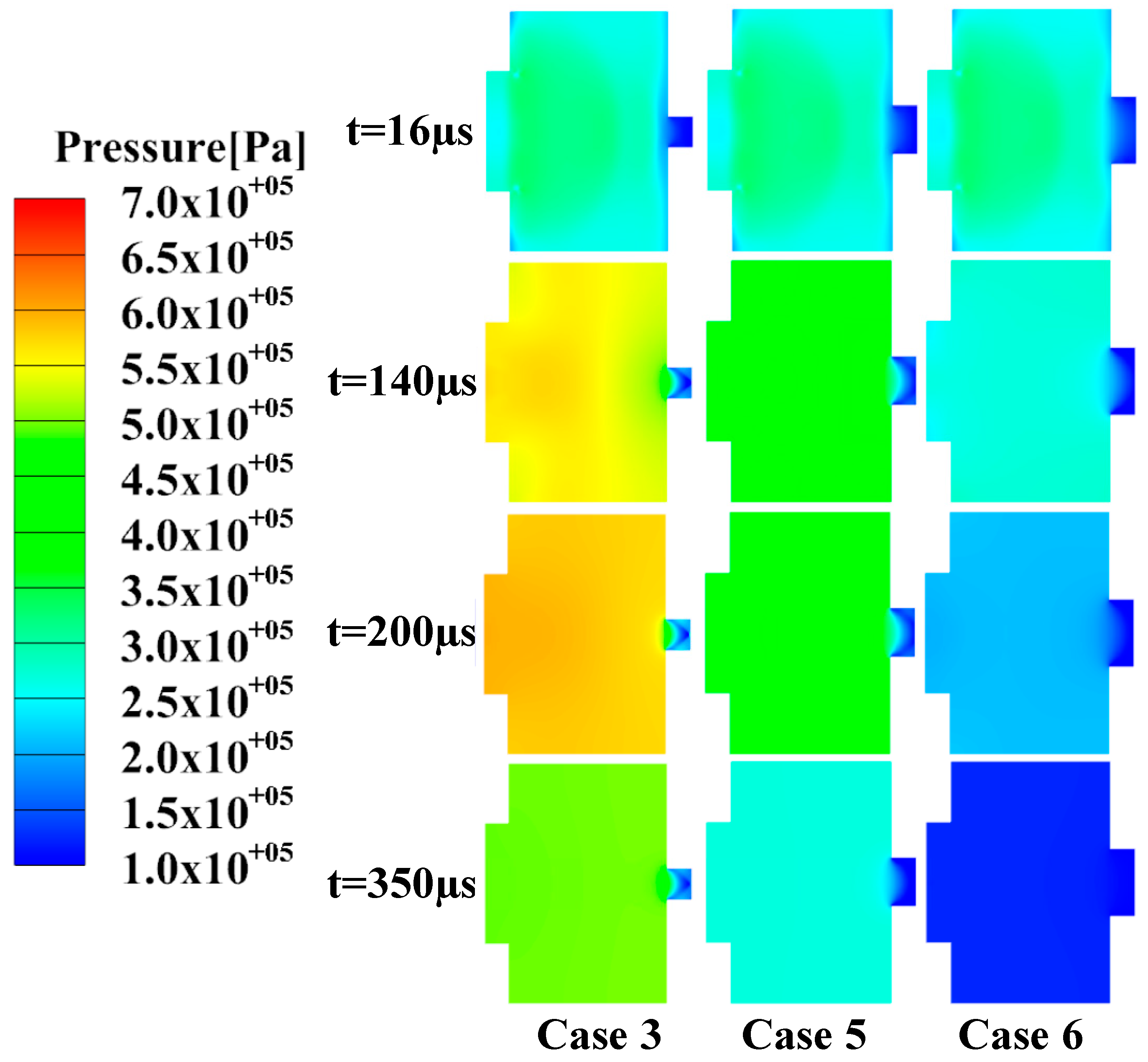
As shown in Figure 15, the peak pressure decreases as the orifice diameter increases. On the other hand, the peak time is shorter. The reason for this is that the blocking effect of the boundary layer thickness on the airflow at the outlet also decreases with the rising orifice diameter, and as a result, the mixture spurts out quickly. In addition, the mass of the leakage of hydrogen increases as the orifice diameter increases, thereby reducing the heat release.
4. Conclusions
To improve the actuator performance, we propose a combined design of a combustion-driven sparkjet actuator. The influences of the actuator length and orifice diameter are numerically investigated. The main conclusions are as follows:
- At a length and orifice diameter of 6.5 mm and 1.3 mm, respectively, the combustion-driven sparkjet actuator has a higher velocity and mass rate than the sparkjet actuator due to the heat release caused by combustion, while the saturation work frequency is almost the same.
- With the rise in volume in the actuator length range from 3.75 to 13 mm, the pressure, orifice velocity and mass rate of the combustion driver increase, whereas the saturation work frequency decreases. The reason for this is that the mixture mass rises as the combustion chamber size increases, which leads to a more heat release from combustion. Meanwhile, as the volume of combustion driver increases, the chemical reaction time increases, resulting in low work frequency.
- The outlet peak velocity, temperature, and pressure increase as the orifice diameter decreases from 2.8 to 1.3 mm. By contrast, the mass flow rate and saturation work frequency trend decrease. The reason for this is that the large orifice diameter reduces the blocking effect of the boundary layer thickness on the airflow at the outlet. Moreover, the mass of the hydrogen leakage increases with the increase in orifice diameter, leading to heat release and temperature decline. Therefore, the structural parameters of the actuator must be optimized reasonably according to different requirements.
Author Contributions
Conceptualization, Y.Z., H.C. and Z.L.; Methodology, H.C. and Y.Z.; Validation, H.C.; Writing—original draft, H.C. and Z.L.; Writing—review & editing, H.C.; Supervision, P.C. All authors have read and agreed to the published version of the manuscript.
Funding
This research was funded by the National Natural Science Foundation of China, Grant No. 92271110, 12002377, and 12072352; and Major national science and technology project No. J2019-III-0010-0054.
Data Availability Statement
Data sharing not applicable. No new data were created or analyzed in this study. Data sharing is not applicable to this article.
Conflicts of Interest
The authors declare no conflict of interest.
References
- Zhang, X.; Li, H.X.; Huang, Y.; Wang, W.B. Wing Flow Separation Control Using Asymmetrical and Symmetrical Plasma Actuator. J. Aircr. 2016, 54, 301–309. [Google Scholar] [CrossRef]
- Kelley, C.L.; Corke, T.C.; Thomas, F.O.; Patel, M.; Cain, A.B. Design and Scaling of Plasma Streamwise Vortex Generators for Flow Sep-aration Control. AIAA J. 2016, 54, 3397–3408. [Google Scholar] [CrossRef]
- Popov, N.A. Kinetics of plasma-assisted combustion: Effect of non-equilibrium excitation on the ignition and oxidation of combustible mixtures. Plasma Sources Sci. Technol. 2016, 25, 043002. [Google Scholar] [CrossRef]
- Frischmuth, T.; Schneider, M.; Maurer, D.; Grille, T.; Schmid, U. Inductively-coupled plasma-enhanced chemical vapour deposition of hydrogenated amorphous silicon carbide thin films for MEMS. Sens. Actuators A Phys. 2016, 247, 647–655. [Google Scholar] [CrossRef]
- Wang, L.; Luo, Z.; Xia, Z.; Liu, B.; Deng, X. Review of actuators for high speed active flow control. Sci. China (Technol. Sci.) 2012, 55, 2225–2240. [Google Scholar] [CrossRef]
- Grossman, K.R.; Cybyk, B.Z.; VanWie, D.M. SparkJet Actuators for Flow Control; AIAA Paper. In Proceedings of the 41st Aerospace Sciences Meeting and Exhibit, Reno, Nevada, 6–9 January 2003. [Google Scholar]
- Hardy, P.; Barricau, P.; Belinger, A.; Caruana, D.; Cambronne, J.P.; Gleyzes, C. Plasma Synthetic Jet for Flow Control; AIAA Paper. In Proceedings of the 40th Fluid Dynamics Conference and Exhibit, Chicago, IL, USA, 28 June–1 July 2010. [Google Scholar]
- Jin, D.; Li, Y.H.; Jia, M.; Song, H.H.; Cui, W.; Sun, Q.; Li, F.Y. Experimental Characterization of the Plasma Synthetic Jet Actuator. Plasma Sci. Technol. 2013, 15, 1034–1040. [Google Scholar] [CrossRef] [Green Version]
- Zhang, Z.B.; Wu, Y.; Sun, Z.Z.; Song, H.M.; Jia, M.; Zong, H.H.; Li, Y.H. Experimental Research on Multichannel Discharge Cir-cuit and Multi-Electrode Plasma Synthetic Jet Actuator. J. Phys. D Appl. Phys. 2017, 50, 165205. [Google Scholar] [CrossRef] [Green Version]
- Tang, M.X.; Wu, Y.; Wang, H.Y.; Jin, D.; Guo, S.G.; Gan, T. Effects of Capacitance on a Plasma Synthetic Jet Actuator with a Conical Cavity. Sens. Actuators A Phys. 2018, 276, 284–295. [Google Scholar] [CrossRef]
- Liu, R.B.; Wang, M.M.; Hao, M.; Lin, Q.; Wang, X.G. Experimental research on air supplementing type plasma synthetic jet generator. Acta Aeronaut. Astronaut. Sin. 2016, 37, 1713–1721. [Google Scholar]
- Li, J.F.; Zhang, X.B. Active Flow Control for Surpersonic Aircraft: A Novel Hybird Synthetic Jet Actuator. Sens. Actuators A Phys. 2020, 302, 111770. [Google Scholar] [CrossRef]
- Wang, L.; Xia, Z.X.; Luo, Z.B.; Chen, J. Three-Electrode Plasma Synthetic Jet Actuator for High-Speed Flow Control. AIAA J. 2014, 52, 879–882. [Google Scholar] [CrossRef]
- Zhou, Y.; Xia, Z.X.; Luo, Z.B.; Wang, L. Effect of Three-Electrode Plasma Synthetic Jet Actuator on Shock Wave Control. Sci. China Technol. Sci. 2017, 60, 146–152. [Google Scholar] [CrossRef]
- Su, W.Y.; Chen, L.H.; Zhang, X.Y. Investigation of magnetohydrodynamic control on turbulent boundary layer separation induced by shock wave. J. Propuls. Technol. 2010, 31, 18–23. [Google Scholar]
- Zhou, Y.; Liu, B.; Wang, L.; Luo, Z.; Xia, Z. Numerical simulation of performance characteristics of two-electrode plasma synthetic jet and the influence of different actuator orifice shapes. Acta Aerodyn. Sin. 2015, 33, 799–805. [Google Scholar]
- Huang, H.X.; Tan, H.J.; Sun, S.; Zhang, Y.C.; Cheng, L. Transient Interaction Between Plasma Jet and Supersonic Compression Ramp Blow. Phys. Fluids 2018, 30, 041703. [Google Scholar] [CrossRef]
- Narayanaswamy, V.; Raja, L.L.; Clemens, N.T. Characterization of a High-frequency Pulsed-plasma Jet Actuator for Su-personic Flow Control. AIAA J. 2010, 48, 297–305. [Google Scholar] [CrossRef] [Green Version]
- Li, L.; Yuan, Z.; Xiang, Y.; Fan, A. Numerical investigation on mixing performance and diffusion combustion characteristics of H2 and air in planar micro-combustor. Int. J. Hydrogen Energy 2018, 43, 12491–12498. [Google Scholar] [CrossRef]
- Kim, W.H.; Park, T.S. Flame characteristics depending on recirculating flows in a non-premixed micro combustor with varying baffles. Appl. Therm. Eng. 2019, 148, 591–608. [Google Scholar] [CrossRef]
- Chen, H.; Liu, W.Q. Numerical Investigation of the Combustion in an Improved Micro combustion Chamber with Rib. J. Chem. 2019, 2019, 8354541. [Google Scholar] [CrossRef]
- Chen, H.; Liu, W.Q. Numerical study of effect of front cavity on hydrogen/air premixed combustion in a micro-combustion chamber. J. Cent. South Univ. 2019, 26, 2259–2271. [Google Scholar] [CrossRef]
- Hua, J.; Meng, W.; Kumar, K. Numerical simulation of the combustion of hydrogen–air mixture in micro-scaled chambers. Part I: Fundamental study. Chem. Eng. Sci. 2005, 60, 3497–3506. [Google Scholar] [CrossRef]
- Zuo, W.; Jiaqiang, E.; Hu, W.; Jin, Y.; Han, D. Numerical investigations on combustion characteristics of H2/air premixed combustion in a micro elliptical tube combustor. Energy 2017, 126, 1–12. [Google Scholar] [CrossRef]
- Crittenden, T.; Glezer, A.; Funk, R.; Parekh, D. Combustion-Driven Jet Actuators for Flow Control; AIAA Paper. In Proceedings of the 15th AIAA Computational Fluid Dynamics Conference, Anaheim, CA, USA, 11–14 June 2001. [Google Scholar]
- Crittenden, T.M.; Warta, B.J.; Glezer, A. Characterization of Combustion Powered Actuators for Flow Control. In Proceedings of the 3rd AIAA Flow Control Conference, San Francisco, CA, USA, 5–8 June 2006. [Google Scholar]
- Rajendar, A.; Crittenden, T.; Glezer, A. Effect of Inlet Flow Configuration on Combustion Powered Actuators; AIAA Paper. In Proceedings of the 48th AIAA Aerospace Sciences Meeting Including the New Horizons Forum and Aerospace Exposition, Orlando, FL, USA, 4–7 January 2010. [Google Scholar]
- Srinivasan, S.; Girgis, B.; Menon, S. Large-Eddy Simulation of a Combustion Powered Actuator; AIAA Paper. In Proceedings of the 44th AIAA/ASME/SAE/ASEE Joint Propulsion Conference & Exhibit, Hartford, CT, USA, 21–23 July 2008. [Google Scholar]
- Crittenden, T. Environmental Testing Of Combustion Powered Actuators for Flow Control; AIAA Paper. In Proceedings of the 37th AIAA Fluid Dynamics Conference and Exhibit, Miami, FL, USA, 25–28 June 2007. [Google Scholar]
- Jee, S.; Bowles, P.O.; Matalanis, C.G.; Min, B.Y.; Wake, B.E.; Crittenden, T.; Glezer, A. Computations of Combustion-Powered Actuation for Dynamic Stall Suppression. In Proceedings of the American Helicopter Society (AHS) Annual Forum, West Palm Beach, FL, USA, 15 July 2016. [Google Scholar]
- He, Z.; Yan, Y.; Zhao, T.; Feng, S.; Li, X.; Zhang, L. Heat Transfer Enhancement and Exergy Efficiency Improvement of a Micro Combustor with Internal Spiral Fins for Thermophotovoltaic Systems. Appl. Therm. Eng. 2021, 189, 116723. [Google Scholar] [CrossRef]
- Smooke, D.M.; Miller, J.A.; Kee, R.J. Determination of Adiabatic Flame Speeds by Boundary Value Methods. Combust. Sci. Technol. 1983, 34, 79–90. [Google Scholar] [CrossRef]
- Akhtar, S.; Kurnia, J.C.; Shamim, T. A three-dimensional computational model of H2–air premixed combustion in non-circular micro-channels for a thermo-photovoltaic (TPV) application. Appl. Energy 2015, 152, 47–57. [Google Scholar] [CrossRef]
- Wang, L.; Luo, Z.B.; Xia, Z.X.; Liu, B. Energy efficiency and performance characteristics of plasma synthetic jet. Acta Phys. Sin. 2013, 62, 125207. [Google Scholar] [CrossRef]
Figure 1.
Three-electrode PSJ actuator.
Figure 2.
Schematic diagram of a combustion-driven actuator.
Figure 3.
Schematic diagram of combustion-driven sparkjet actuator.
Figure 4.
Computational domain and mesh of actuator.
Figure 5.
Position of precursor shock wave and front jet.

Figure 6.
Comparison of actuator orifice velocity with various grids.
Figure 7.
Comparison of actuator performance with different structure parameters.
Figure 8.
Temperature contours of the actuators.

Figure 9.
OH mass fraction of the actuators.
Figure 10.
Pressure contours for various actuators.

Figure 11.
Comparison of actuator performance with different orifice diameters.

Figure 12.
Temperature contours of actuators with different orifice diameters.
Figure 13.
OH mass fraction of actuators with different orifice diameters.
Figure 14.
Mass of the hydrogen leakage of a combustor driver.
Figure 15.
Pressure contours of actuators with different orifice diameters.

Table 1.
Comparison between experimental data and numerical results under adiabatic condition.
| Experimental Results | Numerical Results | |
|---|---|---|
| Temperature (K) | 2382 | 2392 |
| Mass fraction of H2O | 0.323 | 0.317 |
| Mass fraction of O2 | 0.005 | 0.007 |
| Mass fraction of H2 | 0.015 | 0.018 |
| Mass fraction of OH | 0.007 | 0.009 |
| Mass fraction of H | 0.002 | 0.003 |
| Mass fraction of O | 0.001 | 0.0012 |
| Mass fraction of NO | 0.003 | - |
| Mass fraction of N2 | 0.644 | 0.63 |
Table 2.
Structure parameters of actuator.
| Cases | 1 | 2 | 3 | 4 | 5 | 6 |
|---|---|---|---|---|---|---|
| Orifice Diameter | 1.3 mm | 1.3 mm | 1.3 mm | 1.3 mm | 2 mm | 2.8 mm |
| Chamber length | 6.5 mm | 13 mm | 6.5 mm | 3.75 mm | 6.5 mm | 6.5 mm |
Disclaimer/Publisher’s Note: The statements, opinions and data contained in all publications are solely those of the individual author(s) and contributor(s) and not of MDPI and/or the editor(s). MDPI and/or the editor(s) disclaim responsibility for any injury to people or property resulting from any ideas, methods, instructions or products referred to in the content. |
© 2023 by the authors. Licensee MDPI, Basel, Switzerland. This article is an open access article distributed under the terms and conditions of the Creative Commons Attribution (CC BY) license (https://creativecommons.org/licenses/by/4.0/).
Share and Cite
MDPI and ACS Style
Chen, H.; Zhou, Y.; Luo, Z.; Cheng, P. Numerical Investigation of Effect of Structural Parameters on the Performance of a Combustion-Driven Sparkjet Actuator. Actuators 2023, 12, 250. https://doi.org/10.3390/act12060250
AMA Style
Chen H, Zhou Y, Luo Z, Cheng P. Numerical Investigation of Effect of Structural Parameters on the Performance of a Combustion-Driven Sparkjet Actuator. Actuators. 2023; 12(6):250. https://doi.org/10.3390/act12060250
Chicago/Turabian StyleChen, Hai, Yan Zhou, Zhenbing Luo, and Pan Cheng. 2023. "Numerical Investigation of Effect of Structural Parameters on the Performance of a Combustion-Driven Sparkjet Actuator" Actuators 12, no. 6: 250. https://doi.org/10.3390/act12060250
Note that from the first issue of 2016, this journal uses article numbers instead of page numbers. See further details here.