
The UC Softhand: Light Weight Adaptive Bionic Hand with a Compact Twisted String Actuation System

Abstract
:
1. Introduction
- Simpler electromechanical structure
- Lower weight, size and cost
- Simpler control architecture
2. ISR-Softhand


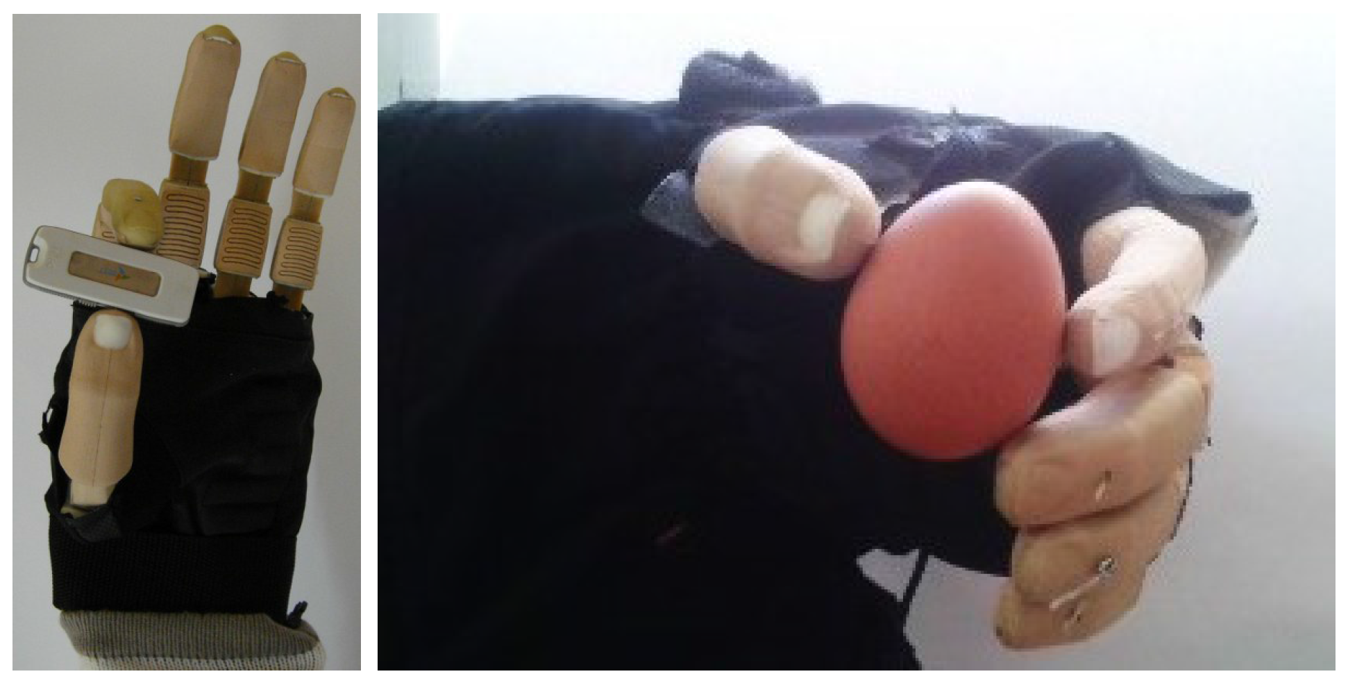
3. The UC Hand
- The design and fabrication of the fingers
- The actuation Strategy
- The actuation mechanism
- The Mechatronics and the control architecture
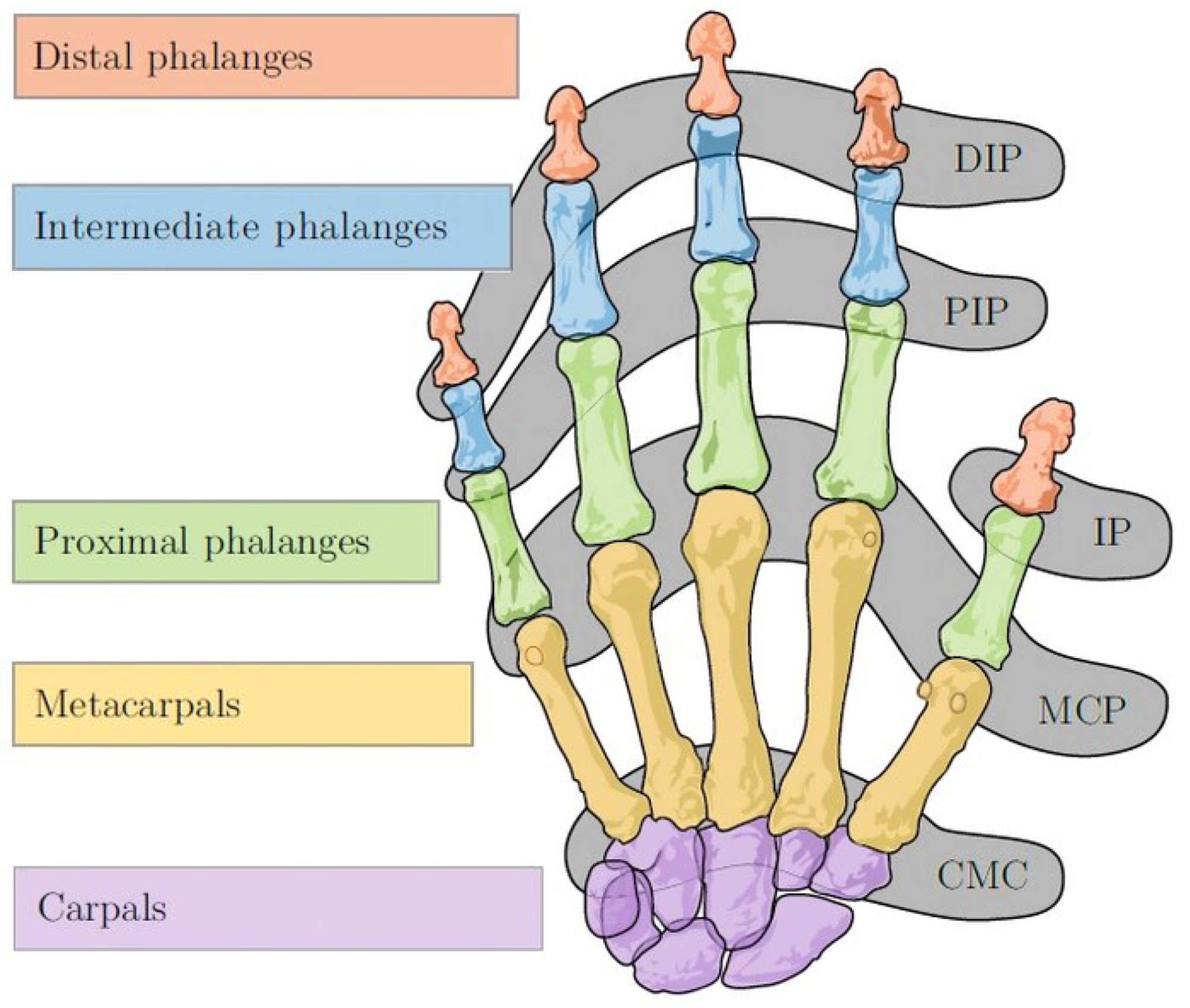
3.1. Design and Fabrication of the Fingers
- An anthropomorphic appearance, i.e., the fingers look like a human finger
- Continuous contact area
- Minimal lateral deflections


3.2. The Actuation Strategy
- Actuator 1: For rotation of the thumb
- Actuator 2: For flexion of the thumb and the index finger
- Actuator 3: For flexion of the other three fingers
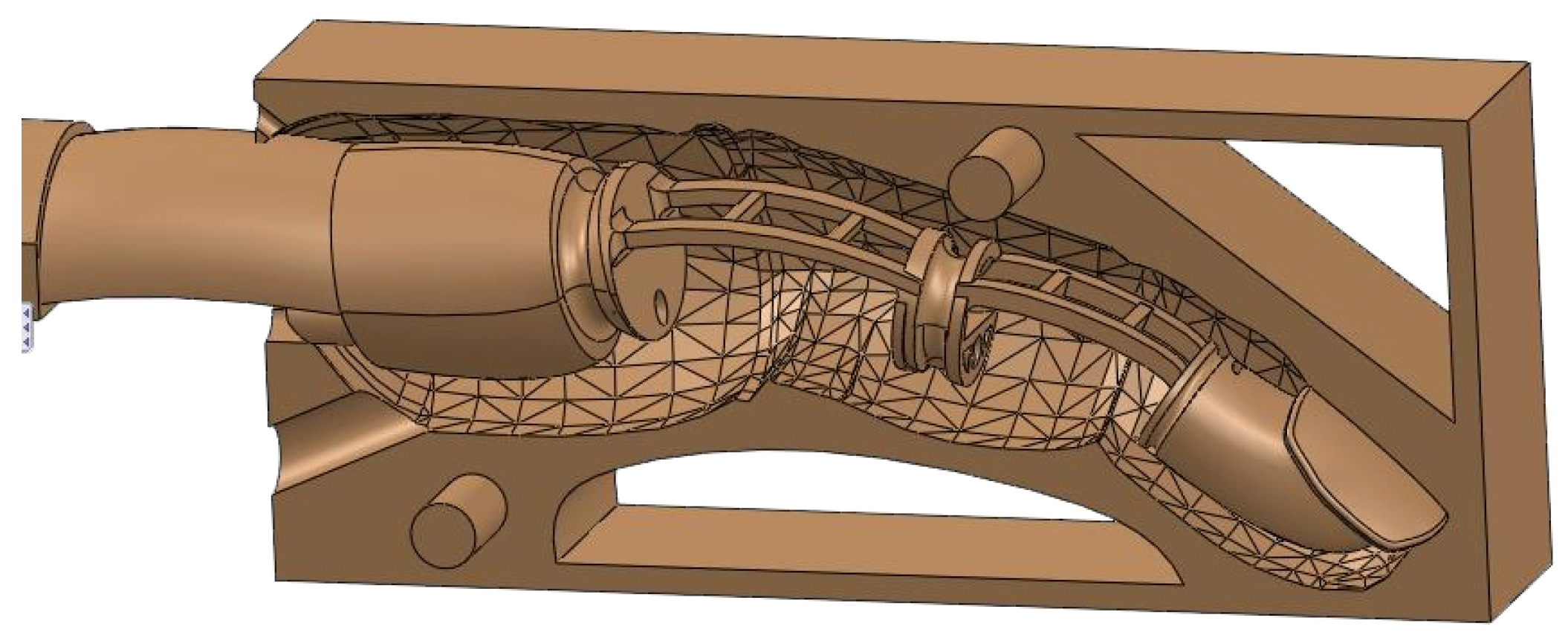
3.3. The Actuation Mechanism
4. The Two-Phase Twisted String System
4.1. Concept


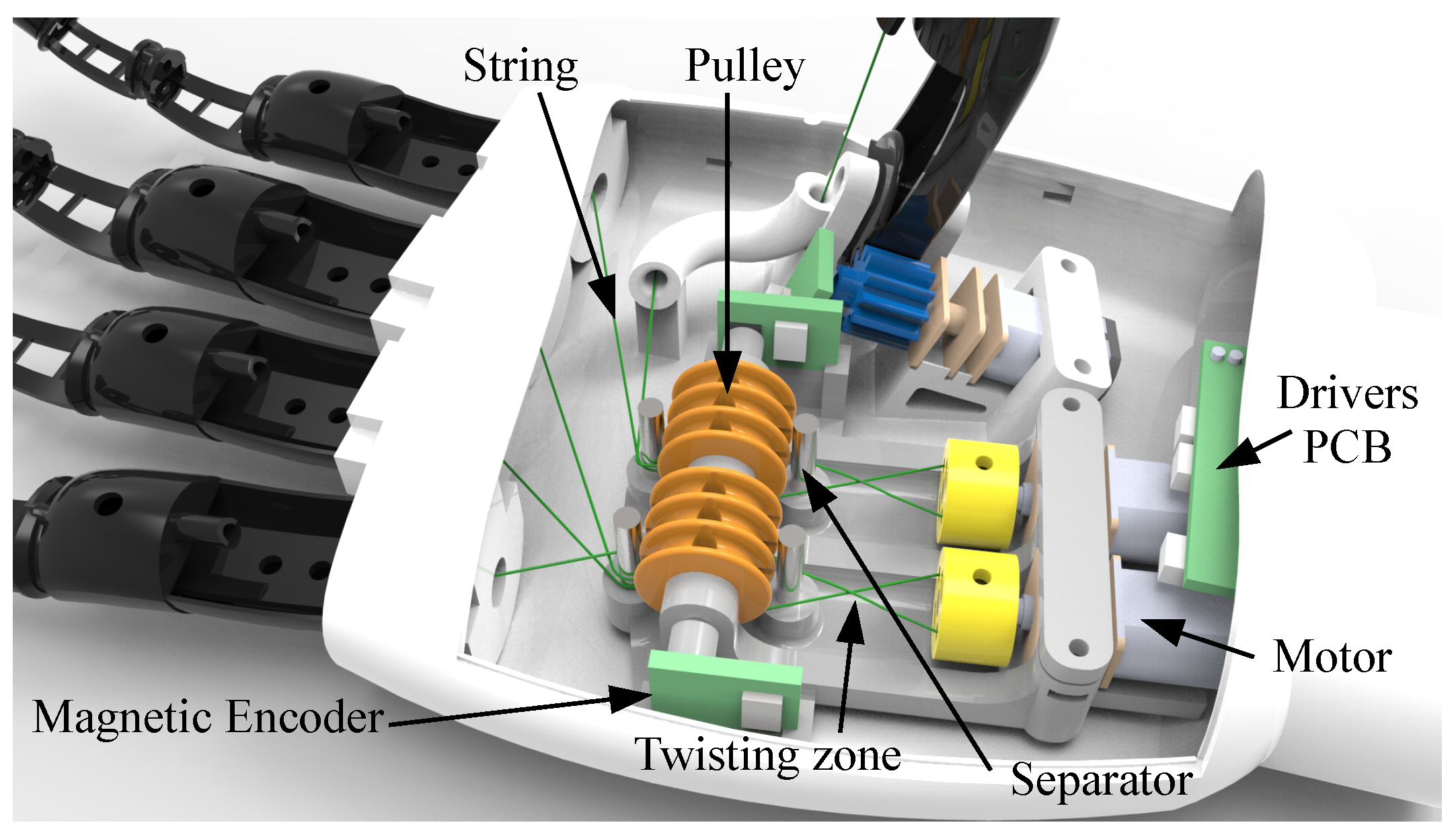
4.2. System Requirements, Design and Integration
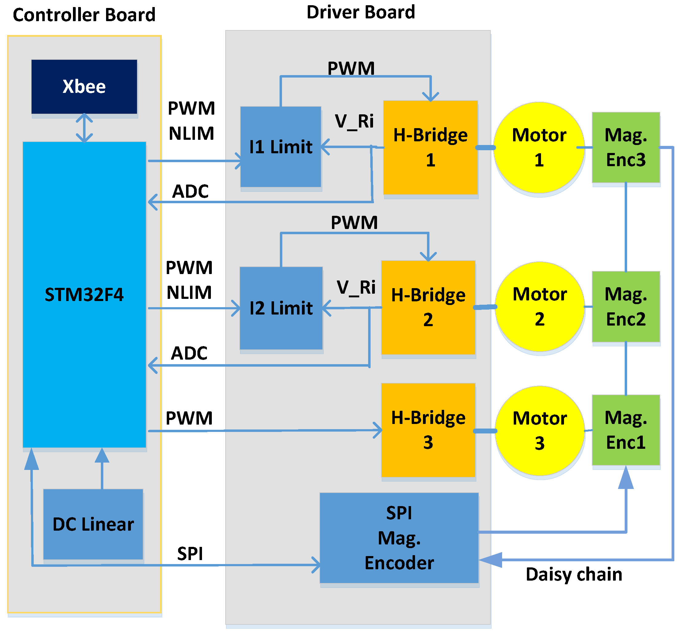

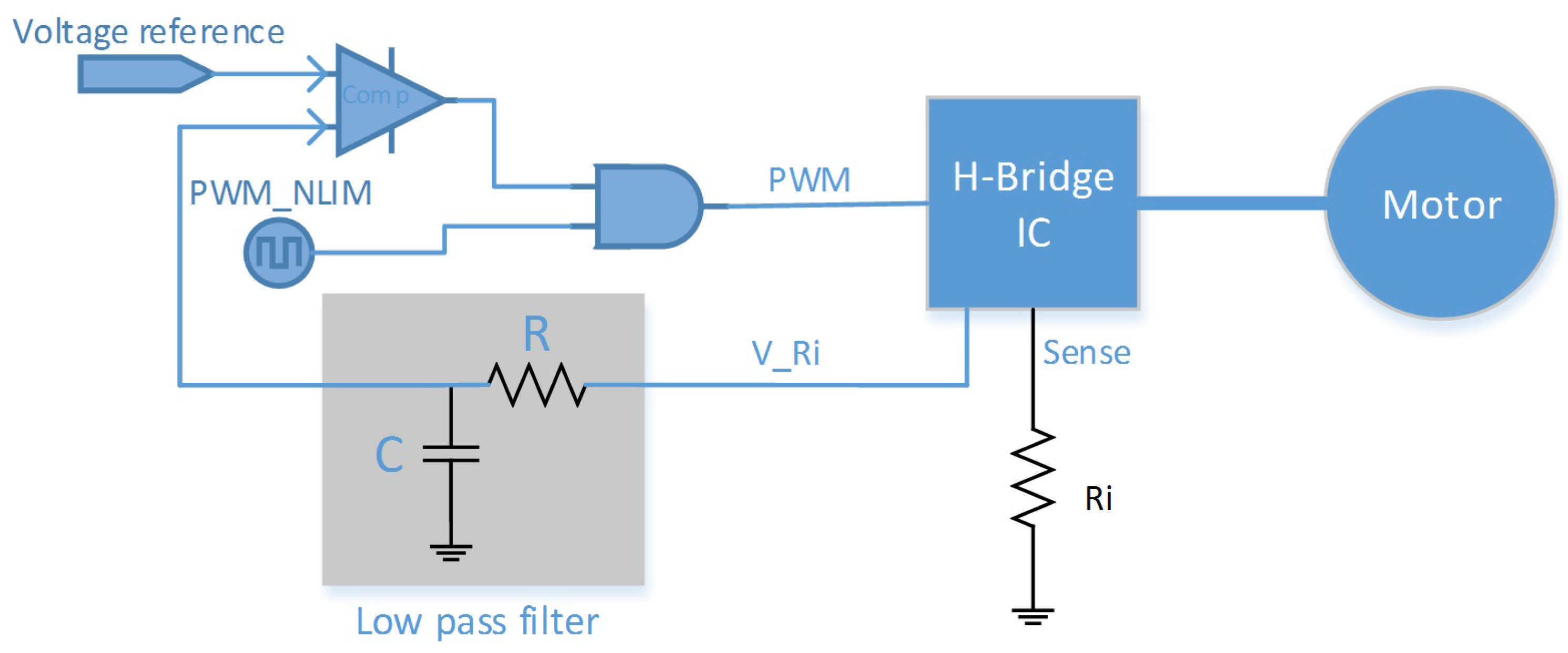
4.3. The Mechatronics and the Control Architecture

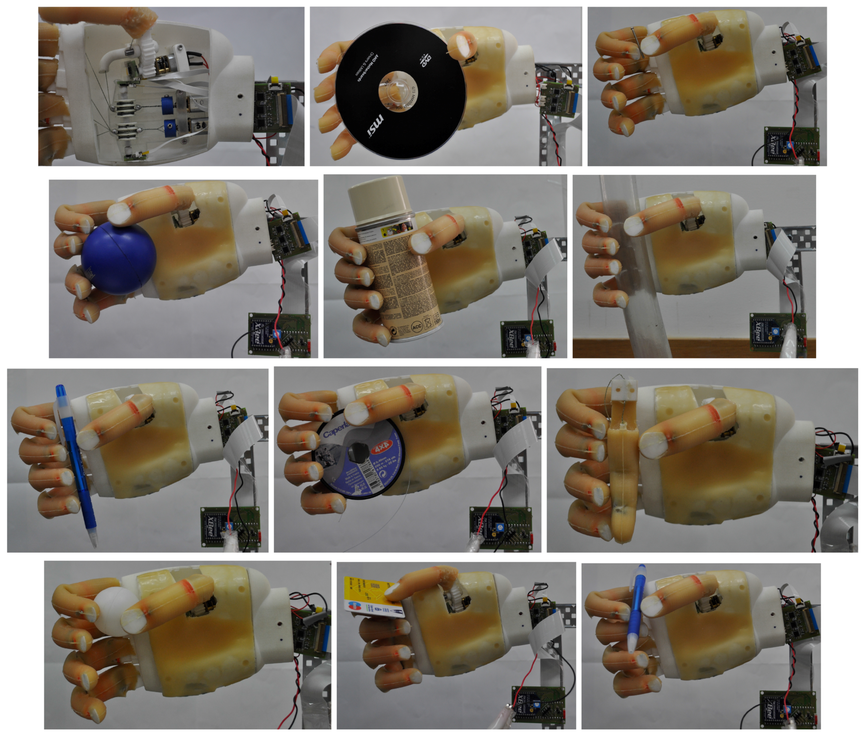
5. Results


| ISR-Softhand | UC-Softhand | |
|---|---|---|
| Number of DOFs | 10 | 10 |
| Number of Actuators | 3 | 3 |
| Size (mm) | 230 × 100 × 80 | 230 × 100 × 40 |
| Mass [g] | 530 | 280 |
| Reduction Mechanism | Gears | Gears and the Twisted String System |
| Control | Position | Position and Torque |
| Non Backdrivable? | No | Yes |
| Actuated thumb rotation | No | Yes |
6. Conclusions
Acknowledgments
Author Contributions
Conflicts of Interest
References
- Mouri, T.; Endo, T.; Kawasaki, H. Review of gifu hand and its Application. Mech. Based Des. Struct. Mach. 2011, 39, 210–228. [Google Scholar] [CrossRef]
- Diftler, M.A.; Mehling, J.; Abdallah, M.E.; Radford, N.A.; Bridgwater, L.B.; Sanders, M.; Askew, R.S.; Linn, D.M.; Yamokoski, J.D.; Permenter, F.; et al. Robonaut 2-the first humanoid robot in space. In Proccedings of the IEEE International Conference on Robotics and Automation (ICRA), Shanghai, China, 9–13 May 2011; pp. 2178–2183.
- Grebenstein, M.; Chalon, M.; Hirzinger, G.; Siegwart, R. Antagonistically driven finger design for the anthropomorphic DLR hand arm system. In Proccedings of the 2010 10th IEEE-RAS International Conference on Humanoid Robots (Humanoids), Nashville, TN, USA, 6–8 December 2010; pp. 609–616.
- Birglen, L.; Gosselin, C.M.; Laliberté, T. Underactuated Robotic Hands; Springer: Berlin, Germany; Heidelberg, Germany, 2008; Volume 40. [Google Scholar]
- Cabas, R.; Cabas, L.M.; Balaguer, C. Optimized design of the underactuated robotic hand. In Proccedings of the IEEE International Conference on Robotics and Automation, Orlando, FL, USA, 15–19 May 2006; pp. 982–987.
- Bullock, I.; Zheng, J.; Rosa, S.; Guertler, C.; Dollar, A. Grasp frequency and usage in daily household and machine shop tasks. IEEE Trans. Haptics 2013, 6, 296–308. [Google Scholar] [CrossRef] [PubMed]
- Feix, T.; Pawlik, R.; Schmiedmayer, H.; Romero, J.; Kragic, D. A comprehensive grasp taxonomy. In Robotics, Science and Systems, Workshop on Understanding the Human Hand for Advancing Robotic Manipulation, Seattle, WA, USA, 28 June–1 July 2009.
- Butterfaß, J.; Grebenstein, M.; Liu, H.; Hirzinger, G. DLR-Hand ii: Next generation of a dextrous robot hand. In Proccedings of the IEEE International Conference on Robotics and Automation, Seoul, Korea, 21–26 May 2001; Volume 1, pp. 109–114.
- MekaBot. Meka H2 Compliant Hand Datasheet; MekaBot: San Francisco, CA, USA, 2009. [Google Scholar]
- Godfrey, S.; Ajoudani, A.; Catalano, M.; Grioli, G.; Bicchi, A. A synergy-driven approach to a myoelectric hand. In Proccedings of the IEEE International Conference on Rehabilitation Robotics (ICORR), Seattle, WA, USA, 24–26 June 2013; pp. 1–6.
- Melchiorri, C.; Palli, G.; Berselli, G.; Vassura, G. Development of the UB hand IV: Overview of Design Solutions and Enabling Technologies. IEEE Robot. Autom. Mag. 2013, 1070, 72–81. [Google Scholar] [CrossRef]
- Tavakoli, M.; de Almeida, A.T. Adaptive under-actuated anthropomorphic hand: ISR-softhand. In Proccedings of the IEEE International Conference on Robotics and Automation, Chicago, IL, USA, 14–18 September 2014.
- Tavakoli, M.; Marques, L.; de Almeida, A.T. Flexirigid, a novel two phase flexible gripper. In Proccedings of the IEEE/RSJ International Conference on Intelligent Robots and Systems (IROS), Tokyo, Japan, 3–7 November 2013; pp. 5046–5051.
- Dollar, A.M.; Howe, R.D. The highly adaptive SDM hand: Design and performance evaluation. Int. J. Robot. Res. 2010, 29, 585–597. [Google Scholar] [CrossRef]
- Tavakoli, M.; Enes, B.; Santos, J.; Marques, L.; de Almeida, A.T. Underactuated anthropomorphic hands: Actuation strategies for a better Functionality. Robot. Auton. Syst. 2015, 74, 267–282. [Google Scholar] [CrossRef]
- Tavakoli, M.; Batista, R.; Neto, P. A compact two-phase twisted string actuation system: Modeling and validation. Mech. Mach. Theory 2016, in press. [Google Scholar]
- Masakazu, S. Complex and Flexible Robot Motions by Strand-Muscle Actuators. In Climbing and Walking Robots: Towards New Applications; InTech education and publishing: Vienna, Austria, 2007. [Google Scholar]
- Suzuki, M.; Ichikawa, A. Toward springy robot walk using strand-muscle Actuators. In Proccedings of the 7th International Conference on Climbing and Walking Robots, Madrid, Spain, 22–24 September 2004; pp. 467–474.
- Suzuki, M.; Mayahara, T.; Ishizaka, A. Redundant muscle coordination of a multi-DOF robot joint by online optimization. In Proccedings of the IEEE International Conference on Advanced Intelligent Mechatronics, Zurich, Switzerland, 4–7 September 2007; pp. 1–6.
- Popov, D.; Gaponov, I.; Ryu, J.-H. Bidirectional elbow ex-oskeleton based on twisted-string actuators. In Proceedings of the IEEE/RSJ International Conference on Intelligent Robots and Systems, Tokyo, Japan, 3–7 November 2013; pp. 5853–5858.
- Park, I.-W.; SunSpiral, V. Impedance controlled twisted string actuators for tensegrity robots. In Proceedings of the 2014 14th International Conference on Control, Automation and Systems (ICCAS), Seoul, Korea, 22–25 October 2014; pp. 1331–1338.
- Gaponov, I.; Popov, D.; Ryu, J.-H. Twisted string actuation systems: A study of the mathematical model and a comparison of twisted strings. IEEE/ASME Trans. Mechatron. 2014, 19, 1331–1342. [Google Scholar] [CrossRef]
- Palli, G.; Natale, C.; May, C.; Melchiorri, C.; Wurtz, T. Modelling and Control of the Twisted String Actuation System. IEEE/ASME Trans. Mechatron. 2013, 18, 664–673. [Google Scholar] [CrossRef]
- Palli, G.; Pirozzi, S.; Natale, C.; de Maria, G.; Melchiorri, C. Mechatronic design of innovative robot hands: Integration and control issues. In Proccedings of the IEEE/ASME International Conference on Advanced Intelligent Mechatronics (AIM), Wollongong, Australia, 9–12 July 2013; pp. 1755–1760.
- Palli, G.; Melchiorri, C.; Vassura, G.; Scarcia, U.; Moriello, L.; Berselli, G.; Cavallo, A.; De Maria, G.; Natale, C.; Pirozzi, S.; et al. The DEXMART Hand: Mechatronic design and experimental evaluation of synergy-based control for human-like grasping. Int. J. Robot. Res. 2014, 33, 799–824. [Google Scholar] [CrossRef]
- Godler, I.; Sonoda, T. A five fingered robotic hand prototype by using twist drive. In Proccedings of the 2010 41st International Symposium and 2010 6th German Conference on Robotics (ROBOTIK), Munich, Germany, 7–9 June 2010; pp. 1–6.
- Feix, T. Anthropomorphic Hand Optimization Based on a Latent Space Analysis. Master’s Thesis, Technische Universität Wien, Wien, Austria, October 2011. [Google Scholar]
- Tavakoli, M.; Enes, B.; Marques, L.; de Almeida, A.T. Actuation strategies for underactuated anthropomorphic hands. In Proccedings of the 2014 IEEE/RSJ International Conference on Intelligent Robots and Systems (IROS 2014), Chicago, IL, USA, 14–18 September 2014; pp. 274–280.
© 2015 by the authors; licensee MDPI, Basel, Switzerland. This article is an open access article distributed under the terms and conditions of the Creative Commons by Attribution (CC-BY) license (http://creativecommons.org/licenses/by/4.0/).
Share and Cite
Tavakoli, M.; Batista, R.; Sgrigna, L. The UC Softhand: Light Weight Adaptive Bionic Hand with a Compact Twisted String Actuation System. Actuators 2016, 5, 1. https://doi.org/10.3390/act5010001
Tavakoli M, Batista R, Sgrigna L. The UC Softhand: Light Weight Adaptive Bionic Hand with a Compact Twisted String Actuation System. Actuators. 2016; 5(1):1. https://doi.org/10.3390/act5010001
Chicago/Turabian StyleTavakoli, Mahmoud, Rafael Batista, and Lucio Sgrigna. 2016. "The UC Softhand: Light Weight Adaptive Bionic Hand with a Compact Twisted String Actuation System" Actuators 5, no. 1: 1. https://doi.org/10.3390/act5010001