
Piezoelectric Transformers: An Historical Review


Micromechatronics, Inc., 200 Innovation Blvd. Suite 155, State College, PA 16803, USA
Actuators 2016, 5(2), 12; https://doi.org/10.3390/act5020012
Submission received: 15 November 2015
/
Revised: 18 April 2016
/
Accepted: 20 April 2016
/
Published: 26 April 2016
(This article belongs to the Special Issue Piezoelectric Actuators)
Abstract
:Piezoelectric transformers (PTs) are solid-state devices that transform electrical energy into electrical energy by means of a mechanical vibration. These devices are manufactured using piezoelectric materials that are driven at resonance. With appropriate design and circuitry, it is possible to step up and step down the voltages between the input and output sections of the piezoelectric transformer, without making use of magnetic materials and obtaining excellent conversion efficiencies. The initial concept of a piezoelectric ceramic transformer was proposed by Charles A. Rosen in 1954. Since then, the evolution of piezoelectric transformers through history has been linked to the relevant work of some excellent researchers as well as to the evolution in materials, manufacturing processes, and driving circuit techniques. This paper summarizes the historical evolution of the technology.
1. Historical Introduction
1.1. 1920s–1930s: Early Studies on Piezoelectric Transformers Using Salt Rochelle Single Crystal
The first studies on electrical to electrical conversion using piezoelectric materials took place in the late 1920s and early 1930s. Alexander McLean Nicolson has the honor of being the first researcher to investigate the idea of a piezoelectric transformer. Nicolson considered two single crystal blocks preloaded against each other with an external frame (Figure 1).
One of the crystal elements was driven with an input electric signal generating a vibration in the crystal. The second crystal element was used to convert the vibration back to an electric energy. The ratio of input to output electric energy was measured to evaluate the energy conversion. The work of Nicolson on piezoelectric transformers, disclosed in multiple patents [1,2,3], was limited to the use of Salt Rochelle single crystals, the only extensively available material at the time. The use of this material led to obvious limitations in performance, design and applicability as compared to the later developed piezoceramic materials.
1.2. 1940s to Early 1960s: Charles A. Rosen’s Work at General Electric, Syracuse, NY, with BaTiO3 Ferroelectric Ceramics
Prior to about 1940, only two types of ferroelectrics were known, Salt Rochelle and some closely related tartrates, and potassium dihydrogen phosphate and its isomorphs [4]. That changed in 1942 with the announcement by Wainer and Salomon [5] of barium titanate (BaTiO3) as a new ferroelectric ceramic. This discovery came to be associated with: (i) the discovery of the electrical poling process in polycrystaline ceramics by Gary and Roberts [6,7]; (ii) the development of the systematics of the piezoelectric effect in polarized ceramics by Mason [8]; and (iii) the extraction of the first values for the piezoelectric coefficients of BaTiO3 by Hans Jaffe in 1948 [9].
Ferroelectric ceramics were quickly recognized to have significant advantages for many electromechanical applications, including ease of fabrication in desired shapes, ability to operate under high humidity, control of response through selection of polarization directions, a high dielectric constant, high electromechanical coupling, and potential low cost. Furthermore, the physical properties of the ceramics could be altered selectively by the use of additive materials and by variations in firing procedures so as to produce the characteristics desired for particular applications. During the late 1940s and through the 1950s, BaTiO3 became commercially available, triggering the proliferation of piezoelectric applications.
During this period, Charles Abraham Rosen (Figure 2), a young researcher that had just joined the team of the Electronics Laboratory at General Electric Company in Syracuse, NY, USA, started working on his doctoral research on piezoelectric transformers using the newly available BaTiO3 and applying the theoretical work developed by Mason. The impact of Rosen’s work in piezoelectric transformer technology has been tremendous. Although his work has been extensively referenced, his figure has been rarely remembered. We want to use some lines of this paper as a tribute to his relevancy in this field.
Born in Canada, Charles Rosen [10,11] received a B.S. degree in Electrical Engineering at Cooper Union, NY, USA, in 1940. He returned to Canada where he spent the period of World War II supervising a group testing Canadian fighter planes before they were sent to battle in Britain. After the war, in 1950, he received his M. Eng. in Communications at McGill University in Montréal (QC, Canada). Shortly after, he joined the General Electric Company (G.E.) team in Syracuse, NY, USA. While at G.E., Rosen worked on solid-state devices and coauthored an influential textbook on transistors [12]. By that time, Rosen entered in the doctoral program at Syracuse University and developed an extended work that established the foundation on piezoelectric ceramic transformer technology. His research work on this area is gathered in several U.S. Patents [13,14,15] and in his doctoral work published in 1956 [16,17].
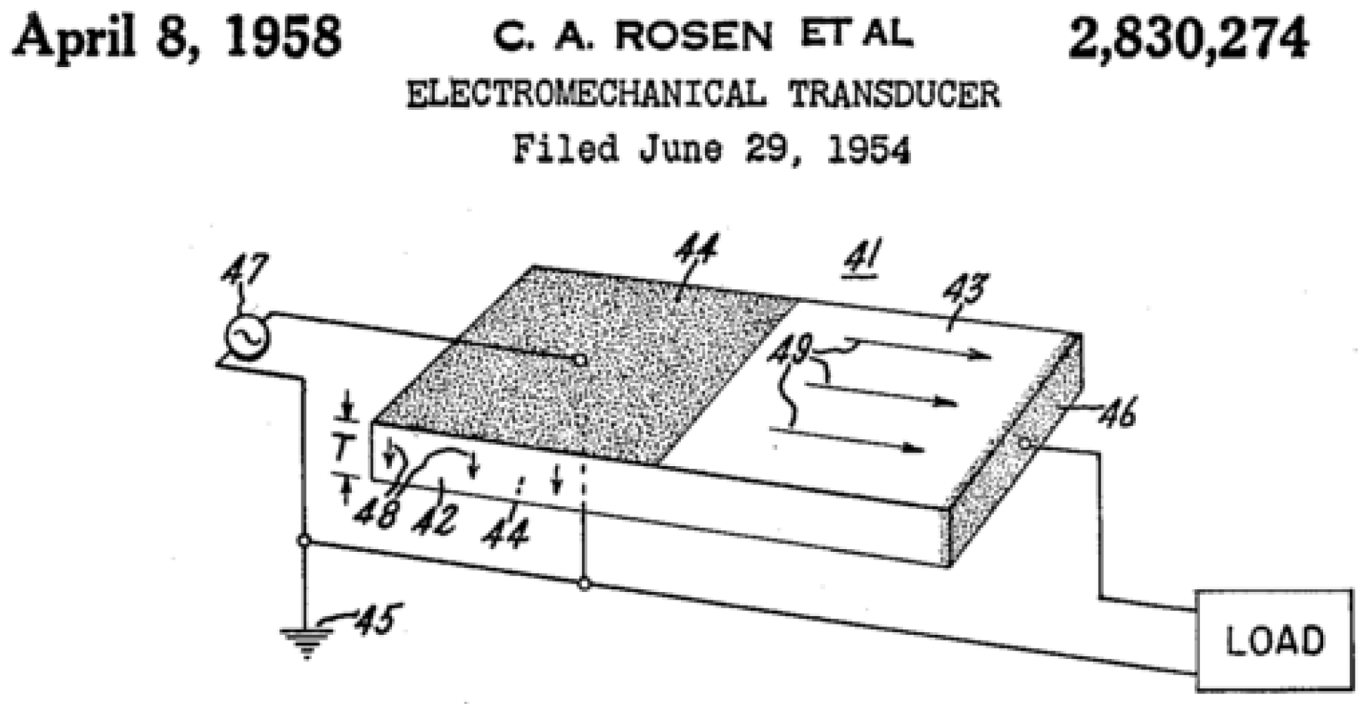
Unlike the earlier attempts by Nicolson to make piezoelectric transformers using two pieces of piezoelectric solid crystals bonded together and clamped with an external structure, Rosen's approach involved the use of a single rectangular block of BaTiO3 polycrystalline ceramic comprising two distinct polarization zones (Figure 3). Rosen created the two zones by applying separated electrodes and different polarizing voltages to the halves of the block. Half of the block was polarized in the longitudinal direction and the other half in the thickness direction. The total length of the ceramic block determines the resonant frequency of the transformer, while the ratio of the input and output sections determines the voltage conversion. The concept was great but the results were poor, because it was very difficult to make a bipolarized block that would not break into pieces when the alternating current was applied. Rosen needed just one unit to prove his concept, but manufacturers had to be able to produce them reliably.
The rectangular piezoelectric transformer of Figure 3 is traditionally known as the “Rosen-type” transformer. Rosen presented several other PT configurations including a cylindrically-segmented PT, a radially polarized disc PT, and a ring-type PT with double polarization. This is summarized in Figure 4. However, none of these other embodiments have gained the attention of the rectangular-type PT. In 1957, Charles Rosen moved to California and joined the Stanford Research Institute where he switched his research into artificial intelligence [10] and became a relevant figure in that field. Rosen passed away in California in 2002, at the age of 85 [10,11].
The work of Rosen was continued by Stephen W. Tehon at the University of Illinois (Urbana, IL, USA). Tehon, also a member of the Electronic Laboratory at General Electric Co. (Syracuse, NY, USA), extended his work to new ferroelectric materials and magnetostrictive materials. His doctoral thesis was published in 1958 [18]. From 1960 to 1962, the team of General Electric at Syracuse continued the work of Rosen and Tehon on ceramic power transformers through a research contract granted by the U.S. Navy [19].
In 1959, H. W. Katz, also a member of the Electronic Laboratory at General Electric Co., edited the book “Solid State Magnetic and Dielectric Devices” [20], with the collaboration of Rosen (by then at Stanford Research Institute, Menlo Park, CA, USA) and Tehon, among others. This is the first published book discussing piezoelectric transformer technology in detail and is still a key reference to any researcher in this field.
1.3. Late 1950s to Late 1960s: Clevite Corporation—Introduction of PZT to PT Technology
Most of the work of the General Electric team on piezoelectric transformers during the 1950s–1960s was based on Barium Titanate, the only commercially available ferroelectric material at the time. This situation changed when, in 1954, Bernard Jaffe recognized the importance of the morphotropic phase boundary in the Lead Zirconate Lead Titanate (PZT) family of ceramics [21,22,23]. Over the decade of the 1960s, B. Jaffe was the head of the research center of the piezoelectric division at the then Clevite Corporation, Bedford, OH, USA, which later became known as Vernitron Corporation, and today is known as Morgan Ceramics. B. Jaffe’s studies were followed by more detailed studies by Hans Jaffe (not a relative of B. Jaffe), William. R. Cooke, Jr., Don A. Berlincourt (all at Clevite Corporation) and others, which led to the evolution of the entire family of PZT piezoceramics. Over the decade of the 1960s, the group led by B. Jaffe, at Clevite Corporation, were unquestionably world leaders in this subject area [24,25,26].
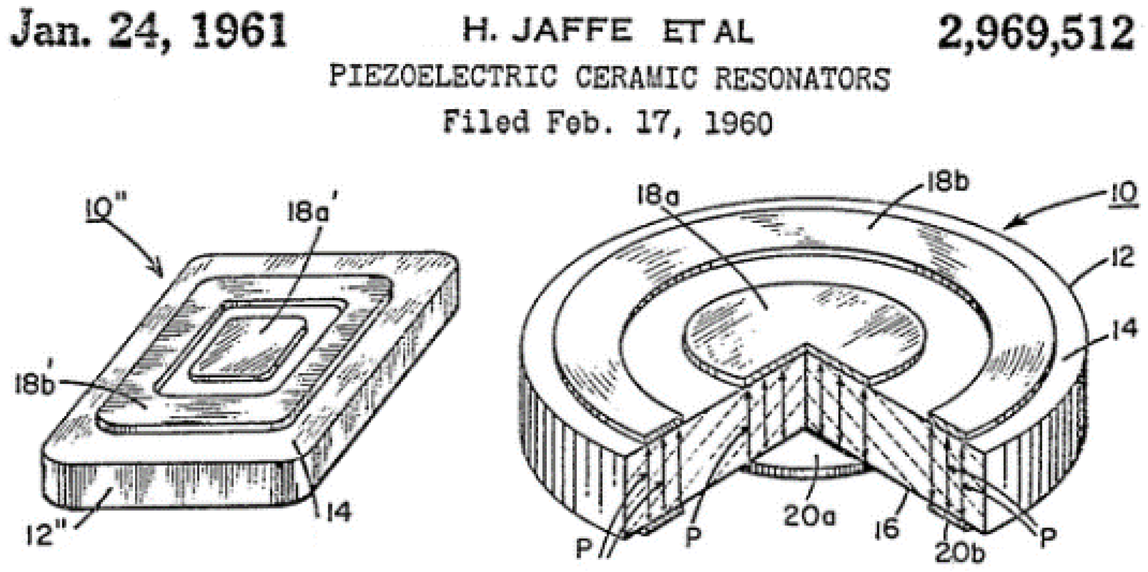
Briefly after the publication of Rosen work, H. Jaffe and D. A. Berlincourt, on behalf of the Clevite Companies, filled for the patent “Piezoelectric Ceramic Resonator” for use in voltage transformation [27]. Strictly speaking, this patent was addressed to the field of ceramic resonators, but the configurations presented in this patent have also been used for piezoelectric transformers. The topology presented by H. Jaffe and Berlincourt consisted of a disc or plate polarized only in the thickness direction and with two separated electrodes representing the input from the output as illustrated in Figure 5.
This topology has been extensively evaluated by many other researchers, not only for piezoelectric transformers but more extensively for ceramic filters and resonators. Perhaps the most appealing characteristic of this topology is the single polarization required for the full ceramic, so the electrodes shape can be obtained by partially etching the full electroded ceramic. In 1965, E. C. Munk presented the equivalent circuit development for the radial modes of the unipoled disc-type configuration [28].
In 1972, Berlincourt patented one of the first specific applications for piezoelectric transformers as starter and ballast for gaseous discharge lamps [29]. In this patent, Berlincourt suggested a variety of configurations for piezoelectric transformers as shown in Figure 6. Among the different configurations, of special relevancy is the rectangular configuration having two sections with thickness polarization (Figure 6a). The configurations of Figure 6b,c correspond to the same topologies illustrated above in Figure 5 as introduced in the 1960 patent by H. Jaffe and Berlincourt.
1.4. Late 1960s–1980s: Period of Proliferation
Until the mid-1960s, piezoelectric transformers were not practical due to the lack of materials able to operate with low mechanical losses at high amplitudes. This situation improved with the introduction of hard-doped piezoelectric ceramic compositions, such as PZT8, showing high mechanical and dielectric Q factors at high amplitudes.
Several U.S. and Japanese companies, like Motorola, Inc. (Chicago, IL, USA) [30,31,32], RCA Corp. (Wilmington, DE, USA) [33,34], Denki Onkyo Co. Ltd. (Tokyo, Japan) [35,36,37,38,39,40,41], and Matsushita Electric Industrial Co. Ltd. (Osaka, Japan) [42], focused their attention to PTs for generating the high voltage required for the cathode-ray tubes in black and white television receivers (see Figure 7b for a typical example). Several attempts were also reported for using piezoelectric transformers as igniter in gas-based stoves (Matsushita Electric Industrial Co. Ltd. [43]), in small engine applications (Briggs & Straton (Milwaukee, WI) [44], Figure 7a) and in automobiles (Nippon Soken, Nishio, Japan) [45]). In the 1980s, Siemens (Berlin, Germany) [46], Figure 7c, and General Electric (Schenectady, NY, USA) [47] were among some companies working on the application of PTs for triggering power switch gates such as triacs, thyristors, Mosfets, etc., with galvanic decoupling.
None of these PT applications reached commercial success because trial production revealed the piezoelectric transformer to be fragile and the overall piezoelectric-solution to be more expensive than the electromagnetic coil it was meant to replace. Some of the technical problems were related to: immature materials fabrication technology, lack of mechanical reliability, inadequate mounting, and bulky driving circuits.
1.5. 1990s–2000s: Commercial Introduction of PTs for CCFL Backlighting
In the late 1980s, several Japanese companies, including NEC Corp. (Kawasaki, Japan), Tokin Corp. (Sendai, Japan), Tamura Corp. (Tokyo, Japan), Matsushita Electric Industrial Co. Ltd., Nihon Cement Kabushiki Kaisha (Tokyo, Japan) and others, reconsidered the use of PTs, taking advantage of improvements in novel piezoelectric materials, more reliable manufacturing technology, including multilayer co-firing processes, new concepts on integrated circuits, and housing solutions. The main application was to generate high voltage for backlighting the small cold cathode fluorescent lamps (CCFLs) used in liquid crystal displays (LCDs) of the increasingly popular portable cell phones and computers. In this application, the piezoelectric transformer enabled thinner, lighter, and more efficient CCFL backlighting modules, thus allowing the reduction of LCD screen thickness and improving the battery life of portable devices. Due to its small size, the cost of the piezoelectric transformers was relatively low and competitive for this application, rapidly enabling high-volume production.
During this period, many technical publications and patents (Figure 8a) were issued for modifications of Rosen’s initial concept, including variations of the design, driving circuitry, mounting solutions, and novel materials to enhance the performance of these devices [48,49,50,51,52,53,54,55]. During the 1990s, CCFL technology enjoyed a significant commercial boom for compact, portable devices. By early the 2000s, it was estimated that 25%–30% of the produced CCFL backlighting circuits were made using piezoelectric transformer technology (Figure 8b).
Companies like Toshiba (Tokyo, Japan), NEC, Hitachi (Tokyo, Japan), Panasonic (Osaka, Japan) and Apple (Cupertino, CA, USA) adopted PT-based backlighting in their laptops. Figure 9 shows a commercial piezoelectric inverters for CCFLs integrated in the Apple MacBook Pro 15″ and 17″ LCD screen computers during the mid-2000s.
In addition to the improvements in the manufacturing process of PTs, developments in the driving techniques for PTs were critical for their commercial success. Two relevant examples are the use of resonant converter topologies for driving the PTs and the use of integrated control circuits to provide stable operation to the PT under different operation conditions.
Resonant converters were originally considered in the early 1990s as an extension of the general approach undertaken in power electronics to use high frequency switching circuits to minimize the size of DC-DC and AC-DC converters. Numerous efforts were undertaken in this area mainly with magnetic components [56]. In general, to drive a PT, either a sine wave or a square wave voltage can be used. A sine wave voltage is preferred for minimizing the circulating energy through the shunt input capacitance characteristic of the input of the PT. However, generating a sine wave requires more reactive components in the converter than generating a square wave. With resonant converters, the sine input waveform is generated by using a square wave voltage in combination with an inductive element in series with the transformer. The control of the ON/OFF of the switches of the converter is selected to minimize the switching losses. This technique is the so-called Zero Voltage Switching, ZVS [57]. The combination of the ZVS technique and the PT can reduce the capacitive turn-on loss due to the input capacitance of the PT, and achieve high efficiency.
There are two main strategies to achieve ZVS in a PT-driven topology. First, and most common, the PT should present an inductive characteristic at the operating frequency. In order to achieve this, normally an inductor is connected in series with the PT. In this type of strategy, the PT can be driven at a fixed duty cycle of 0.5. A second approach to achieve ZVS is to use the PT without an external inductor (so-called “inductor-less” driving). In this case, a variable duty-cycle is required for the control signal to the Mosfets to achieve ZVS.
Figure 10 shows some of the standard topologies [54] used to drive PTs using a series inductor, including push-pull [53], half-bridge and Class-E [57,58,59]. Inductor-less techniques is discussed in Section 1.6.
In order to ensure the ZVS condition and to maintain the stability of the converter under load and input voltage fluctuation, strategies for controlling the PTs were developed and integrated within ICs. The first control circuits were designed as fixed frequency oscillators near the resonant frequency. However, due to the high mechanical quality factor (Q), of the PT, changes in the resonant frequency associated with aging, temperature, load variation, or input voltage, could not be compensated for, negatively affecting the performance of the PT.
Progressively, different control schemes have been developed to ensure the stability of the output voltage or current, as well as maximize the circuit efficiency under different operation conditions. Since PTs are frequency-dependent devices, a way to control the operation of the PT is to vary the frequency according to output load changes or to input voltage variations.
One of the first control techniques introduced was the so-called “frequency control,” sometimes referred as PFM (pulse frequency modulation). Frequency control requires one or several feedback control loops. These feedback loops provide information about the output voltage (or current) variations so they can be appropriately regulated. Different companies such as Rohm (Tokyo, Japan (BA9785 [58], BA9802), Sanyo (Tokyo, Japan) (LA5663V), Texas Instrument (Dallas, TX, USA) (UCC3975 [59]), O2 Micro (Santa Clara, CA, USA) (OZ9913), and Maxim (Sunnyvale, CA, USA) (MAX8785), among others, have developed ICs integrating a combination of these strategies to provide full control of the PTs. There are several possibilities that have been proposed regarding the parameters to be measured to determine the frequency control, including:
In some applications, the use of a single frequency loop cannot ensure the complete control of the PT under large variations of the input voltage and/or the output load. When this happens, the frequency shift required in the transformer to adjust the output conditions may be so large that the efficiency of the PT will be significantly affected or/and the correct transformation ratio to achieve the expected values is not possible. In order to overcome these limitations, a second voltage feedback loop control is sometimes considered to extend the regulation range of the converter.
The voltage feedback has been implemented in two basic ways. One proposed option is to use pulse modulation technique to control the driving circuit signal of the transistor gates (PWM technique). The second alternative includes the control of the input DC voltage by using a chopper circuit controlled at much lower frequency than the PT (for instance, 100–1000 Hz), which switches the input voltage to the switching transistor. This sometimes referred as “dimming technique”.
By the late 2000s and early 2010s, the CCFL backlighting technology used for LCD started to be replaced by light-emitting diodes (LEDs). This resulted in a production decline of high voltage piezoelectric transformers and eventually stopped the high-volume production of these components by most of the leading suppliers. This also impacted the production of IC and many of the specifically designed ICs for the CCFL business are currently discontinued.
1.6. Beyond the 2000s: Power Piezoelectric Transformers
The evolution in the know-how of PT technology during the 1990s and first decade of 2000s inspired new developments beyond the CCFL backlighting in areas such as fluorescent ballasts, AC-DC battery adapters and, more recently, for AC-DC LED drivers. Compared to backlighting inverters, where the typical power level is 5 W and the output voltage is several hundred volts (step up), most DC-DC or AC-DC applications require several tenths to hundreds of watts with output voltage levels of just a few volts (step-down conversion). The Rosen PT topology is not suitable for those levels of power conversion since its design is prominent in high voltage generation. Thus, new types of PTs designs and revisions of some previously suggested were considered by researcher interested in power conversion applications. The effort was mainly led by two companies: Face Electronics in the U.S. and NEC in Japan. Other groups in Europe and Korea, with alternative proposals, followed these tendencies toward power applications.
Strictly speaking, the first published research effort on power PTs was undertaken in 1966 by Othmar M. Stuetzer [60] of Sandia Laboratory (Albuquerque, NM, USA). Stuetzer analyzed the power capabilities of a PT consisting of two thin piezoelectric discs bonded to opposite sides of a metal wall and operating in the thickness mode (Figure 12). In spite of this earlier and mainly theoretical study, no other work on high-power PTs is mentioned until the 1990s.
Early in the 1990s intense work was re-initiated in Japan by NEC on the same concept of thickness mode PTs (Figure 13) and its use for power applications. Some of the proposed thickness mode designs consisted of 1 to 2 mm-thick plates with input and output multilayer sections and operating at very high frequencies, such as 1 MHz or higher. T. Inoue, O. Ohnishi, Y. Sasaki, among others at NEC, hold several of the patents for thickness mode PT [61,62] designs.
One of the main operational challenges of using a thickness mode is the large number of high order modes for the longitudinal or width extensional vibrations resulting in spurious modes near the thickness mode resonance frequency. The reason is related to the fact that PZT ceramics have high electromechanical coupling factor kt necessary for thickness operation, but also have large coupling factor k31 for longitudinal and width vibrations. The k31 large coupling factor results in a large number of high-order harmonics that couple with the thickness mode, leading to poor operational characteristics. To suppress the spurious resonances, based on the unstiffened piezoelectric effect, ceramic materials with large anisotropy were considered, in particular the PbTiO3 ceramic material, where kt is larger than 50% and k31 is less than 5% [63].
Simultaneously with the development and improvement in PT designs for power applications, intensive work, also by NEC, resulted in publications on circuit strategies to drive the PTs on power applications [64,65,66,67]. During this period, activities were initiated at Virginia Power Electronic Center (VPEC) of Virginia Tech University, led by Fred Lee, on converters using piezoelectric transformers [68,69,70]. These activities were in part the result of the collaboration between VPEC and NEC. In July 1993, T. Zaitsu, a member of NEC team, joined as a visiting researcher the Virginia Power Electronic team at Virginia Tech [65]. He stayed for one year, until August 1994, and returned to Japan where he continued his work at NEC [71,72] and published his doctoral dissertation in 1997 [73].
The evaluation of thickness expansion mode PTs by NEC demonstrated that these transformers can deliver higher net output power due to their higher driving frequency. However, it was found that their efficiency was low, in the high 80% range, and their integration in DC-DC converters was difficult due to limitations relating to efficient driving circuits (especially field-effect transistor, FETs) for such frequency and large output power. In 1997, NEC changed its focus to a different type of piezoelectric transformer, the longitudinal vibration mode transformer shown in Figure 14 [71].
The longitudinal transformer provided better efficiency than the thickness mode transformer. In addition, the multilayer construction of both the input and output allowed better design flexibility for AC-DC adapter integration [72,73,74,75,76,77].
Toward the mid-1990s, Face Electronics, Norfolk, VA, USA, invented a new concept of power PT, Transoner® (registered name by Face Electronics, Figure 15), based on a laminated construction [78]. The Transoner radial operation and a symmetric design was included in a second patent by A. V. Carazo [79]. The power density, design flexibility, manufacturing simplicity and toughness of the Transoner have resulted in this design becoming the reference for power applications in many research publications.
In the late 1990s and early 2000s, the VPEC at Virginia Tech began a characterization study of Transoner piezoelectric transformer, funded in part by a grant from Virginia’s Center for Innovative Technology (CIT), and also by Face Electronics [80,81]. The objective of this collaboration led to intensive research in the area of fluorescent ballast using piezoelectric transformers. Perhaps the most relevant outcome of this research was the development of a new inductor-less concept to drive piezoelectric transformers (Figure 16), which eliminated the input series inductor used in previous driving approached [82,83,84].
Also, late in the 1990s, shortly after the invention of Transoner, NEC switched the research on power PTs to a different type of PT, using a similar approach as the Transoner Face’s radial piezoelectric transformer. The NEC approach used a square geometry with an internal radial electrode [85,86], operated in a contour-extensional vibration mode (Figure 17).
The use of Transoner PTs and the concept of inductor-less driving techniques was followed by several other research groups, including Ben-Gurion University (Beersheba, Israel) of the Negev, Beer-Sheva, Israel [87,88,89].
Several other research groups have investigated other structures for step-down conversion. The unipoled PT, originally developed by Berlincourt in late 1960s, is one of the topologies that have also been considered by several researchers for step-down applications.
In Europe, Alcatel Spain, Ferroperm, Denmark, the Universidad Politécnica de Madrid, Spain, and the Universidad de Oviedo, Spain, collaborated in the ESPRIT IV project “TRAMST” for the development of a piezoelectric AC-DC converter for mobile phone battery chargers. The PT design was based on a ring-shaped element operating in thickness vibrational mode, where the primary and secondary sections are separated by an isolation layer [90,91,92,93,94,95,96,97,98,99,100].
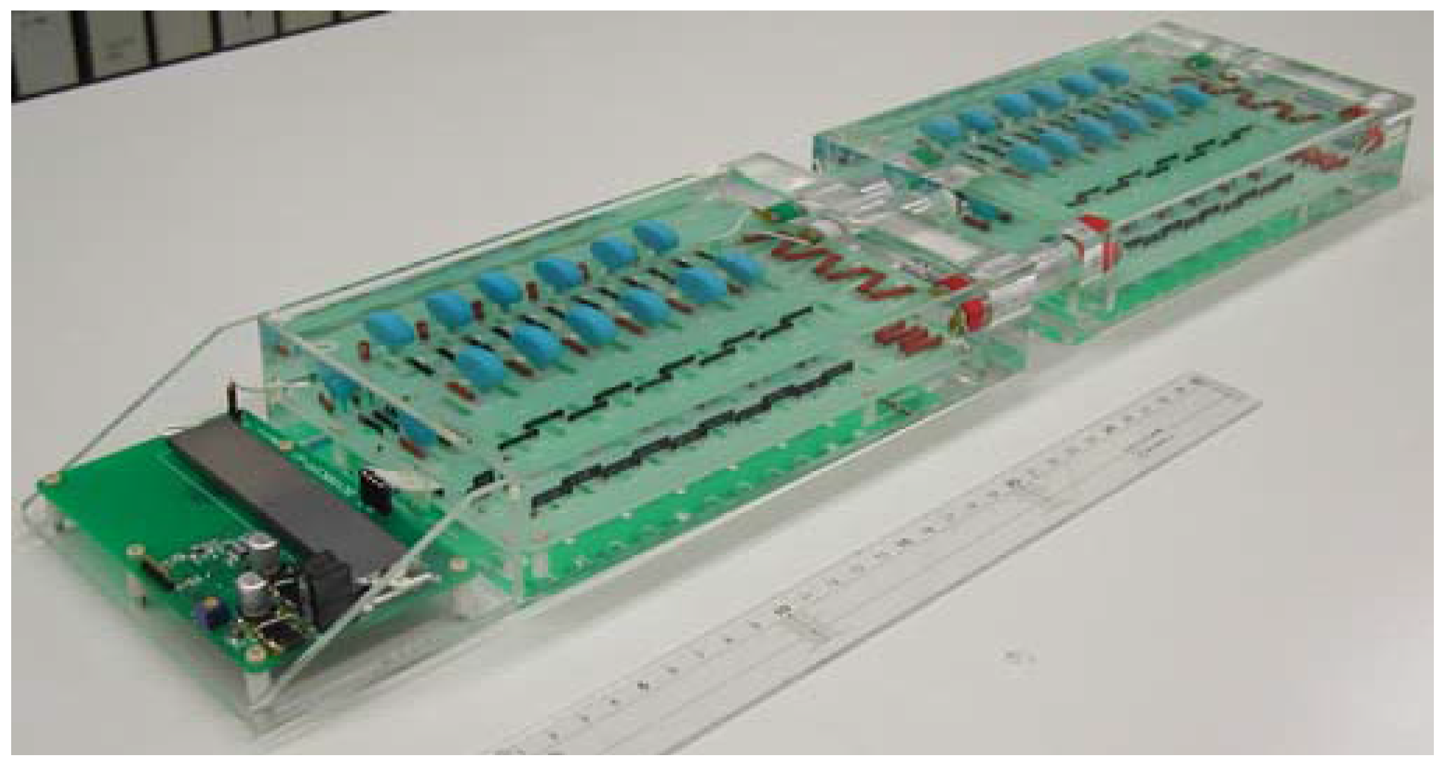
In the mid-2000s, Face Electronics, Fraunhofer Institute, led by Matthias Radecker, and Infineon, collaborated in several research projects on the application of piezoelectric transformers, including the development of a control IC [101,102,103,104,105]. One of the outcomes of this work was the development of a duty cycle control strategy implemented by a mathematical function that set the duty cycle to meet ZVS depending on the frequency [106]. Figure 18 shows a 40 W isolated radial piezoelectric transformer designed for a 24 V piezoelectric AC-DC battery charger for universal input applications (85–265 V), which was the result of this development collaboration.
Late in the 2000s and the early 2010s, work was done at the University of Sheffield, UK, by E. L. Horsley on Transoner radial PT and its application to inductor-less converters [107,108,109].
Recently, a research line on piezoelectric transformers has been established at the Department of Electrical Engineering of the Technical University of Denmark, led by Michael A. E. Andersen. The main focus of this research work is on inductor-less and bidirectional piezoelectric transformer-based converters [110,111,112,113,114].
Currently, the development, production and sale of Transoner radial transformers is done at Micromechatronics, Inc., State College, Pennsylvania, USA, under the same technical team that started the development of the technology at Face.
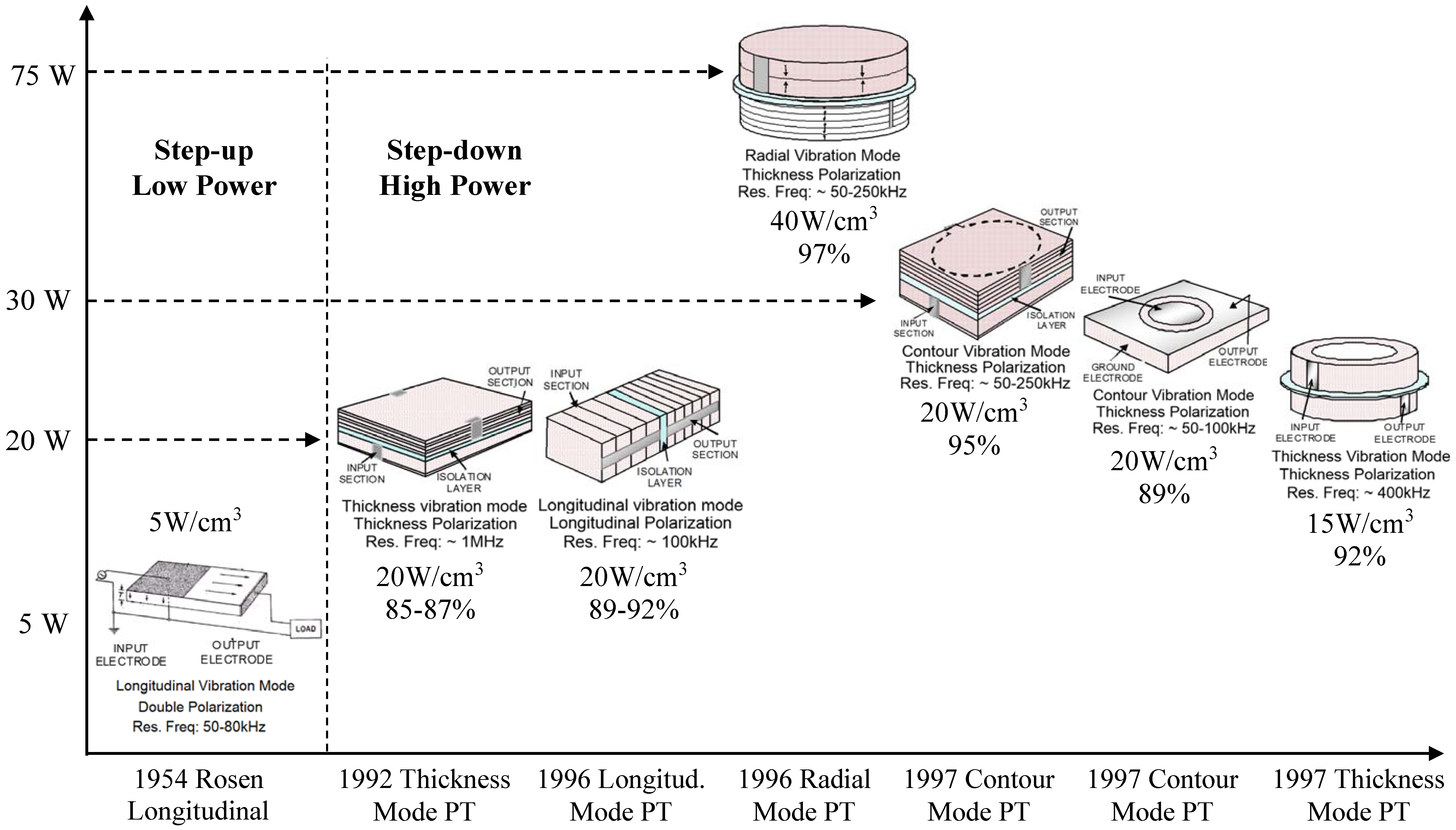
Figure 19 illustrates a summary of the most relevant power transformers configurations that has been considered through the state of the art.
2. Space, Defense and Security Applications of Piezoelectric Transformers
During the 2000s, NASA granted several Small Business Innovation Research (SBIR) projects to integrate piezoelectric transformers into space applications [115].
2.1. High Voltage Piezoelectric-Based Power Supply to Drive the Main Payload of Satellite Communication Systems: The Traveling Wave Tube
This NASA SBIR-founded research program, led by Dr. Carazo, developed a piezoelectric-based electronic power conditioner (EPC) module to supply power to traveling wave tubes (TWTs) used for space-earth long-distance wireless communication [116,117,118]. The developed design eliminated conventional electromagnetic transformers with a compact and highly efficient piezoelectric transformer driver. The developed EPC unit consisted of several modules providing different levels of high voltage and power to the different circuits of a TWT. Figure 20 illustrates the concept of the project (Figure 20a) and one of the developed EPC modules used to drive a 4 kV/10 W cathode of the TWT.
2.2. Development of New Integrated Ignition Systems for Small Satellite Thruster by Using Piezoelectric Transformer Technology
This NASA SBIR-founded research program developed a new discharge initiation (DI) system using a piezoelectric transformer to initiate the discharge of Pulsed Plasma Thrusters used in small satellites using solid-state spark-plugs [119,120,121,122]. The program took as a reference the design specifications of the PPT development for the Earth Orbit experimental satellite (EO-1) launched in November 2000. The complete prototype of the system (called IGNIT-SONER) was tested in May 2005 at NASA Glenn Research Center under high vacuum conditions (10−6 to 10−7 torr) for over 50,000 accumulated cycles. Moreover, the unit was tested for over 500,000 accumulated cycles under atmospheric lab conditions under maximum firing rates of 5 Hz. The developed transformer is an input to output 3 kV-isolated PT, and able to step up the input voltage to over 2.5 kV. The physics associated with semiconductor-type spark plugs used for ignition under vacuum conditions led to the development of a piezoelectric-to-capacitive discharge topology. This topology allows the storing the high voltage energy delivery by the piezoelectric transformer in a capacitor, and then suddenly releasing it to the spark-plug. This sudden release makes it possible to achieve very high current levels of over 100 A for few microseconds, as required to generate the spark. Figure 21a shows one of the IGNIT-SONER developed prototypes. Figure 21b shows the vacuum chamber at NASA Glenn where the prototype was tested.
2.3. High Voltage Power Supplies for Compact Neutron Generators
This project developed a very high voltage, (1 MV) and high power, (40 W) piezoelectric-driven power supply to drive compact neutron generators. The power supply is based on a modular stackable system which combines piezoelectric transformers and Cockroft-Walton voltage multiplier circuits [123,124]. Figure 22 illustrates a 200 kV stage using the high voltage/high power piezoelectric transformer driving a multi-stage Cockroft-Walton circuit.
3. Other Applications of Piezoelectric Transformers
3.1. High Voltage Non-Resonant Piezoelectric Transformer for Monitoring High Voltage Networks
One of the less usual fields of applications was proposed in the late 1990s by the University Politecnica de Catalunya, Spain, by A. V. Carazo in his doctoral thesis research [125]. In this work, a non-resonant piezoelectric transformer construction was evaluated as a high voltage measurement transducer for high voltage networks. Figure 23a shows one of the prototypes inside of a high voltage testing chamber. The figure shows the external epoxy isolating housing inside of which there is a large piezoelectric actuating unit connected to a high voltage, and a small sensor unit connected that provides low voltage. Both units are mechanically connected but electrically isolated, as shown the sketch of Figure 23b. The unit was designed for 36 kV.
3.2. Piezoelectric Transformers for Isolation Feedback and Gate Driver Applications
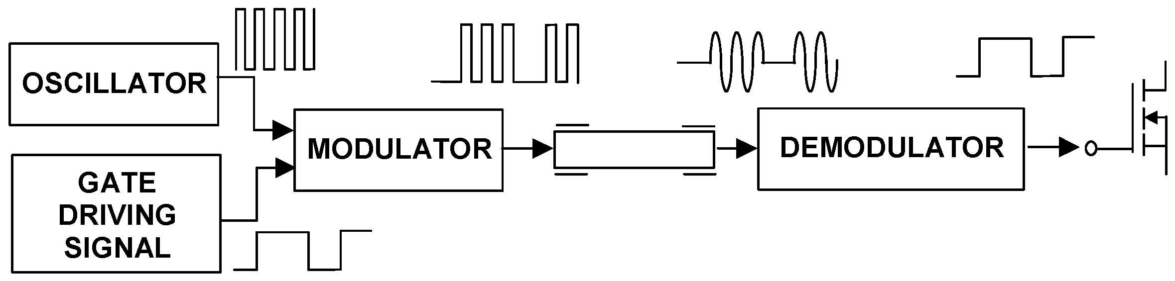
There have been several publications recently on the use of piezoelectric transformers to isolate feedback circuits [126,127,128], as well as for driving the gate of Mosfet transistors while providing isolation. This topic was initially considered in the 1980s [46,47] and there is now renewed interest with innovative technologies. Piezoelectric transformers provide an excellent isolation means, simultaneously providing power and signal transfer to drive the gate of transistors. Figure 24 exemplifies the use of PTs for control of the gate of a Mosfet. In this case, the control gate signal is modulated to the resonance frequency required for driving the PT. In the output of the PT, a demodulator circuit, which may consist of a rectifier circuit, converts the signal back into the input control signal.
4. Conclusions
During the mid-1990s and through the first decade of 2000s, piezoelectric transformers spread widely to a diverse range of applications. The main area of application was high voltage piezoelectric inverters for CCFL backlighting used in laptop computers LCD panels. Other applications included ozone generators for medical, sanitary and beauty related applications and air cleaners. The non-magnetic characteristic of PTs, their compact size, their ability to generate high voltages, and their high power density was a perfect match for portable applications. During this period, it was estimated that the total sales per year exceeded 25–30 million with the main production located in Japan.
Toward the end of the 2000s, the LCD backlighting technology transitioned from the use of CCFLs to LEDs. This has resulted in a progressive decline in sales of high voltage piezoelectric transformers. Most of the manufacturers of PTs for CCFL backlighting have now discontinued their production. Some production still remains for some ionizing products using single layer-type PTs.
Significant research has been done on the applicability of PTs for other commercial uses, such as power converters for AC-DC and DC-DC applications. For these applications, the required PTs are typically the step-down type, isolated, and with higher power requirements. The cost and limitation of readily available products are one of the main challenges in extending the applicability of power transformers.
Currently, the main area of interest of piezoelectric transformers is in medical, defense, security and sensitive measurement equipment, where the PT can offer a differential value added compared to magnetic transformers, even at a higher cost.
Conflicts of Interest
The authors declare no conflict of interest.
References
- Nicolson, A.M. Piezo-Electric Crystal Transformer. U.S. Patent No. 1,829,234, 25 January 1927. [Google Scholar]
- Nicolson, A.M. Multiple Piezo-Electric Transformer. U.S. Patent No. 1,863,345, 11 March 1927. [Google Scholar]
- Nicolson, A.M. Piezoelectric Crystal Converter-Generator. U.S. Patent No. 1,975,517, 2 May 1931. [Google Scholar]
- Jaffe, B.; Cook, W.R., Jr.; Jaffe, H. Piezoelectric Ceramics, 1st ed.; Academic Press: New York, NY, USA, 1971; pp. 1–5. [Google Scholar]
- Wainer, E.; Salomon, A.N. Electrical Reports of the Titanium Alloy Manufacturing Division, Report 10; National Lead Co.: Winchester, MA, USA, 1943. [Google Scholar]
- Gray, R.B. Transducer and Method of Making the Same. U.S. Patent No. 2,486,560, 20 September 1946. [Google Scholar]
- Roberts, S. Dielectric and piezoelectric properties of barium titanate. Phys. Rev. 1947, 71, 890–895. [Google Scholar] [CrossRef]
- Mason, W.P. Electrostrictive effect in barium titanate ceramics. Phys. Rev. 1948, 74, 1134–1147. [Google Scholar] [CrossRef]
- Jaffe, H. Properties of electromechanical ceramics. Electronics 1948, 21, 128–130. [Google Scholar]
- Hart, P.E.; Nilsson, N.J.; Perrault, R.; Mitchell, T.; Kulikowski, C.A. In Memoriam: Charles Rosen, Norman Nielsen and Saul Amarel. AI Mag. 2003, 24, 6–12. [Google Scholar]
- Softky, M. Charles Rosen, Robotics Pioneer, Dies at 85; The Almanac: San Mateo, CA, USA, 2002. [Google Scholar]
- Rosen, C.A. Principles of Transistor Circuits; Shea, R.F., Ed.; John Wiley & Sons, Inc.: New York, NY, USA, 1953. [Google Scholar]
- Rosen, C.A.; Fish, K.A.; Rothenberg, H.C. Electromechanical Transducer. U.S. Patent No. 2,830,274, 29 January 1954. [Google Scholar]
- Rosen, C.A. Electromechanical Transducer. U.S. Patent No. 2,974,296, 26 May 1959. [Google Scholar]
- Rosen, C.A. Electrical Conversion Apparatus. U.S. Patent No. 2,975,354, 30 November 1956. [Google Scholar]
- Rosen, C.A. Analysis and Design of Ceramic Transformers and Filters. Ph.D. Thesis, Syracuse University, Syracuse, NY, USA, 1956. [Google Scholar]
- Rosen, C.A. Ceramic transformers and filters. In Proceedings of the 7th Electronic Components Symposium, Washington, DC, USA, 1–3 May 1956; pp. 205–211.
- Tehon, S.W. Piezoelectric and Magnetostrictive Transducers. Ph.D. Thesis, University of Illinois, Urbana, IL, USA, 1958. [Google Scholar]
- Tehon, S.W. Final Report for Ceramic Power Transformers, General Electric Company to Navy Department, BuShips Contract NObsr-81369, June 1960–January 1962; General Electric Company: Syracuse, NY, USA, 1962. [Google Scholar]
- Rosen, C.A.; Tehon, S.W. Solid State Magnetic and Dielectric Devices; Katz, H.W., Ed.; John Wiley & Sons, Inc.: London, UK, 1959; pp. 170–197. [Google Scholar]
- Jaffee, B.; Roth, R.S.; Marzullo, S. Piezoelectric properties of lead zirconate-lead titanate solid-solution ceramic ware. J. Appl. Phys. 1954, 25, 809–810. [Google Scholar] [CrossRef]
- Jaffe, B. Piezoelectric Transducers Using Lead Titanate and Lead Zirconate. U.S. Patent No. 2,708,244, 24 March 1954. [Google Scholar]
- Jaffee, B.; Roth, R.S.; Marzullo, S. Morphotropic Piezoelectric Ceramics. U.S. Patent No. 2,849,404, 13 April 1956. [Google Scholar]
- Cross, L.E.; Newnham, R.E. Remembering Bernard Jaffe. Ferroelectrics 1984, 51, 157–158. [Google Scholar] [CrossRef]
- Cross, L.E.; Newnham, R.E. History of ferroelectric. In Ceramics and Civilization, Volume III. High-Technology Ceramics-Past, Present, and Future; The American Ceramic Society: Westerville, OH, USA, 1987; pp. 289–305. [Google Scholar]
- Fujishima, S. The history of ceramic filters. IEEE Trans. Ultrason. Ferroelectr. Freq. Control 2000, 47, 1–7. [Google Scholar] [CrossRef] [PubMed]
- Jaffe, H.; Berlincourt, D.A. Piezoelectric Ceramic Resonators. U.S. Patent No. 2,969,512, 17 February 1960. [Google Scholar]
- Munk, E.C. The equivalent electrical circuit for radial modes of a piezoelectric ceramic disc with concentric electrodes. Philips Res. Rep. 1965, 20, 170–189. [Google Scholar]
- Berlincourt, D.A. Piezoelectric Starter and Ballast for Gaseous Discharge Lamps. U.S. Patent No. 3,764,848, 15 March 1972. [Google Scholar]
- Schafft, H.W. Piezoelectric Voltage Transforming Device. U.S. Patent No. 3,281,726, 10 October 1963. [Google Scholar]
- Schafft, H.W. Voltage Generation Utilizing Piezoelectric Effects. U.S. Patent No. 3,397,328, 14 June 1966. [Google Scholar]
- Kramer, D.A. Power Supply Circuit Employing Piezoelectric Voltage Transforming Device. U.S. Patent No. 3,657,579, 16 April 1971. [Google Scholar]
- Mccusker, J.H.; Perlman, S.S. Ferro-Electric Transformers with Means to Suppress or Limit Resonant Vibrations. U.S. Patent No. 3,683,211, 1 April 1971. [Google Scholar]
- Lim, C.C. Piezoelectric Ultra-Voltage Generator for a Television Receiver. U.S. Patent No. 4,459,505, 28 May 1982. [Google Scholar]
- Inoue, K. Self-Exciting Type High Voltage Generating Apparatus Utilizing Piezoelectric Voltage Transforming Elements. U.S. Patent No. 3,679,918, 19 June 1970. [Google Scholar]
- Inoue, K. High Voltage Generating Apparatus. U.S. Patent No. 3,694,674, 25 September 1970. [Google Scholar]
- Kawada, T. Apparatus for Driving Piezoelectric Transformers. U.S. Patent No. 3,708,701, 18 March 1971. [Google Scholar]
- Kawada, T. Driving Apparatus for Piezoelectric Ceramic Elements. U.S. Patent No. 3,743,868, 12 October 1971. [Google Scholar]
- Kawada, T. Piezoelectric Transformers. U.S. Patent No. 3,778,648, 28 June 1972. [Google Scholar]
- Kawada, T. High Voltage Generating Device Having an Operating Monitoring Device. U.S. Patent No. 3,790,826, 19 December 1972. [Google Scholar]
- Kawada, T. Corona Discharge Apparatus for Particle Collection. U.S. Patent No. 3,900,766, 2 November 1973. [Google Scholar]
- Sasaki, R.; Kitani, T. A High-Voltage Generator Circuit Configuration Utilizing a Ceramic Transformer. U.S. Patent No. 3,598,909, 25 July 1968. [Google Scholar]
- Ansai, Y.; Mifune, H.; Tani, K. Gas Ignition Device. U.S. Patent No. 4,054,936, 16 March 1976. [Google Scholar]
- Harkness, J.R. Reciprocating Engine Spark Ignition Apparatus. U.S. Patent No. 3,173,055, 21 December 1961. [Google Scholar]
- Tanaka, T.; Yorita, H.; Tomita, M.; Igashira, T. High Voltage Generating Device. U.S. Patent No. 4,767,967, 4 June 1985. [Google Scholar]
- Kleinschmidt, P.; Magori, V. Trigger Device and Piezo-Ignition Coupler with Galvanic Decoupling. U.S. Patent No. 4,392,074, 9 April 1981. [Google Scholar]
- Leskovec, R.A.; Davenport, J.M.; Burman, O.B. Autoresonant Piezoelectric Transformer Signal Coupler. U.S. Patent No. 4,584,499, 12 April 1985. [Google Scholar]
- Tsuchiya, H. Ceramic transformers made from titanates. J. Inst. Electr. Eng. Jpn. 1961, 81, 603–609. (In Japanese) [Google Scholar]
- Kaname, Y.; Ise, Y. A study of transducer design of piezoelectric ceramic transformers. J. Acoust. Soc. Jpn. 1976, 32, 470–479. (In Japanese) [Google Scholar]
- Kawashima, S.; Ohnishi, O.; Hakamata, H.; Tagami, S.; Fukuoka, A.; Inoue, T.; Hirose, S. Third order longitudinal mode piezoelectric ceramic transformer and its application to high-voltage power inverter. In Proceedings of the 1994 IEEE Ultrasonics Symposium, Cannes, France, 31 October–3 November 1994; pp. 525–530.
- Tagami, S.; Shimada, Y.; Kawashima, S.; Isobe, K.; Ohnishi, O.; Inoue, T.; Hirose, S. Color-LCD backlight inverter utilizing piezoelectric ceramic transformer. SID Symp. Dig. Tech. Pap. 1995, 26, 382–385. [Google Scholar]
- Sugimoto, M.; Shimada, Y.; Furuhashi, N.; Taihaku, N. Very compact inverter for color LCD backlight utilizing a packaged piezoelectric ceramic transformer. SID Symp. Dig. Tech. Pap. 1996, 27, 757–760. [Google Scholar]
- Shoyama, M.; Horikoshi, K.; Ninomiya, T.; Zaitsu, T.; Sasaki, Y. Operation analysis of the push-pull piezoelectric inverter. In Proceedings of the APEC Conference, Atlanta, GA, USA, 23–27 February 1997; Volume 2, pp. 573–578.
- Piezoelectric Transformers. Application Note Philips Magnetic Products; Philips Components: Eindhoven, The Netherlands, 1997.
- Sasaki, Y.; Yamamoto, M.; Ochi, A.; Inoue, T.; Takahashi, S. Small multilayer piezoelectric transformers with high power density—Characteristics of second and third-mode Rosen-type transformers. Jpn. J. Appl. Phys. 1999, 38, 5598–5602. [Google Scholar] [CrossRef]
- Mohan, N.; Undeland, T.M.; Robbins, W.P. Power Electronics: Converters, Applications, and Design; John Wiley & Sons, Inc.: New York, NY, USA, 1989. [Google Scholar]
- Ninomiya, T.; Shoyama, M.; Zaitsu, T.; Inoue, T. Zero-voltage techniques and their application to high-frequency converter with piezoelectric transformer. In Proceedings of the 20th International Conference on Industrial Electronics, Control and Instrumentation, Bologna, Italy, 5–9 September 1994; Volume 3, pp. 1665–1669.
- Data Sheet BA9825FV Piezo-Electric Transformer Inverter Control IC; Rohm Co., Ltd.: Tokyo, Japan, 2004.
- Data Sheet UCC3975, UCC3976, UCC3977, Multi-Topology Piezoelectric Transformer Controller, SLUS499A; Texas Instruments Inc.: Dallas, TX, USA, 2001.
- Stuetzer, O.M. Linear Theory of Piezoelectric Transformers; Sandia Laboratory Report No. SC-RR-66-414; Sandia Laboratories: Albuquerque, NM, USA, 1966.
- Inoue, T.; Ohnishi, O.; Ohde, N. Thickness Mode Vibration Piezoelectric Transformer. U.S. Patent No. 5,118,982, 30 May 1990. [Google Scholar]
- Sasaki, Y.; Uehara, K.; Inoue, T. Piezoelectric Ceramic Transformer Being Driven with Thickness Extensional Vibration. U.S. Patent No. 5,241,236, 1 April 1992. [Google Scholar]
- Ohnishi, O.; Kishie, H.; Iwamoto, A.; Sasaki, Y.; Zaitsu, T.; Inoue, T. Piezoelectric ceramic transformer operating in thickness extensional vibration mode for power supply. In Proceedings of the 1992 IEEE Ultrasonics Symposium, Tucson, AZ, USA, 20–23 October 1992; pp. 483–488.
- Zaitsu, T.; Inoue, T.; Ohnishi, O.; Iwamoto, A. 2 MHz power converter with piezoelectric ceramic transformer. In Proceedings of the 14th International Telecommunications Energy Conference, Washington, DC, USA, 4–8 October 1992; pp. 430–437.
- Zaitsu, T.; Ohnishi, O.; Inoue, T.; Shoyama, M.; Ninomiya, T.; Lee, F.C.; Hua, G.C. Piezoelectric transformer operating in thickness extensional vibration and its application to switching converter. In Proceedings of the 25th Annual IEEE Power Electronics Specialists Conference and Exposition, Taipei, Taiwan, 20–25 June 1994; pp. 585–589.
- Zaitsu, T.; Shigehisa, T.; Inoue, T.; Shoyama, M.; Ninomiya, T. Piezoelectric transformer converter with frequency control. In Proceedings of the 17th International Telecommunications Energy Conference, The Hague, The Netherlands, 29 October–1 November 1995; pp. 175–180.
- Zaitsu, T.; Shigehisa, T.; Shoyama, M.; Ninomiya, T. Piezoelectric transformer converter with PWM control. In Proceedings of the Eleventh Annual Applied Power Electronics Conference and Exposition, San Jose, CA, USA, 3–7 March 1996; pp. 279–283.
- Lin, C.Y.; Lee, F.C. Development of a piezoelectric transformer converter. In Proceedings of the Virginia Power Electron. Center (VPEC) Sem., Blacksburg, VA, USA, 19–21 September 1993; pp. 79–85.
- Lin, C.Y.; Lee, F.C. Design of a piezoelectric transformer converter and its matching networks. In Proceedings of the 25th Annual IEEE Power Electronics Specialists Conference and Exposition, Taipei, Taiwan, 20–25 June 1994; pp. 607–612.
- Lin, C.Y. Design and Analysis of Piezoelectric Transformer Converters. Ph.D. Thesis, Virginia Tech, Blacksburg, VA, USA, 1997. [Google Scholar]
- Zaitsu, T.; Fuda, Y.; Okabe, Y.; Ninomiya, T.; Hamamura, S.; Katsuno, M. New piezoelectric converter for AC-adapter. In Proceedings of the Twelfth Annual Applied Power Electronics Conference and Exposition, Atlanta, GA, USA, 23–27 February 1997; Volume 2, pp. 568–572.
- Zaitsu, T. AC/DC Converter with a Piezoelectric Transformer. U.S. Patent No. 5,969,954, 15 January 1998. [Google Scholar]
- Zaitsu, T. Power Conversion Using Piezoelectric Transformers. Ph.D. Thesis, Kyushu University, Fukuoka, Japan, 1997. [Google Scholar]
- Katsuno, M.; Fuda, Y. Piezoelectric transformers using inter-digital internal electrodes. In Proceedings of the 1998 IEEE Ultrasonics Symposium, Sendai, Japan, 5–8 October 1998; Volume 1, pp. 897–900.
- Yamane, T.; Hamamura, S.; Zaitsu, T.; Ninomiya, T.; Shoyama, M.; Fuda, Y. Efficiency improvement of piezoelectric transformer DC-DC converter. In Proceedings of the 29th Annual IEEE Power Electronics Specialists Conference, Fukuoka, Japan, 17–22 May 1998; Volume 2, pp. 1255–1261.
- Hamamura, S.; Zaitsu, T.; Ninomiya, T.; Shoyama, M. Noise characteristics of piezoelectric-transformer DC-DC converter. In Proceedings of the 29th Annual IEEE Power Electronics Specialists Conference, Fukuoka, Japan, 17–22 May 1998; Volume 2, pp. 1262–1267.
- Hu, J.; Fuda, Y.; Katsuno, M.; Yoshida, T. A study on the rectangular-bar-shaped multilayer piezoelectric transformer using length extensional vibration mode. Jpn. J. Appl. Phys. 1999, 38, 3208–3212. [Google Scholar] [CrossRef]
- Bishop, R.P. Multi-Layer Piezoelectric Transformer. U.S. Patent No. 5,834,882, 27 May 1997. [Google Scholar]
- Carazo, A.V. Multilayer Piezoelectric Transformer. U.S. Patent No. 6,614,144, 4 October 2001. [Google Scholar]
- CIT Challenge Award (ELC-99-007). Transoner Characterization; Virginia Tech: Blacksburg, VA, USA, 1999. [Google Scholar]
- CIT Challenge Award (ELC-00-006). Linear Ballast Development; Virginia Tech: Blacksburg, VA, USA, 2000. [Google Scholar]
- Lin, R.L.; Baker, E.; Lee, F. Characterization of piezoelectric transformers. In Proceedings of the Power Electronics Seminars at Virginia Tech, Blacksburg, VA, USA, 19–21 September 1999; pp. 219–225.
- Lin, R.L. Piezoelectric Transformer Characterization and Application of Electronic Ballast. Ph.D. Thesis, Virginia Tech, Blacksburg, VA, USA, 2001. [Google Scholar]
- Lin, R.L.; Lee, F.C.; Baker, E.M.; Chen, D.Y. Inductor-less piezoelectric transformer electronic ballast for linear fluorescent lamp. In Proceedings of the 16th Annual IEEE Applied Power Electronics Conference and Exposition, Anaheim, CA, USA, 4–8 March 2001; Volume 2, pp. 664–669.
- Hamamura, S.; Kurose, D.; Ninomiya, T.; Yamamoto, M. New control method of piezoelectric transformer converter by PWM and PFM for wide range of input voltage. In Proceedings of the IEEE CIEP, Acapulco, Mexico, 15–19 October 2000; pp. 3–8.
- Yamamoto, M.; Sasaki, Y.; Ochi, A.; Inoue, T.; Hamamura, S. Step-down piezoelectric transformer for AC-DC converters. Jpn. J. Appl. Phys. 2001, 40, 3637–3642. [Google Scholar] [CrossRef]
- Ivensky, G.; Zafrany, I.; Ben-Yaakov, S. Generic operational characteristics of piezoelectric transformers. In Proceedings of the 31st Annual IEEE Power Electronics Specialists Conference, Galway, Ireland, 18–23 June 2000; Volume 3, pp. 1657–1662.
- Bronstein, S.; Ben-Yaakov, S. Design considerations for achieving ZVS in a half bridge inverter that drives a piezo transformer with no series inductor. In Proceedings of the 33rd Annual IEEE Power Electronics Specialists Conference, Cairns, Queensland, Australia, 23–27 June 2002; Volume 2, pp. 585–590.
- Ben-Yaakov, S.; Lineykin, S. Frequency tracking to maximum power of piezoelectric transformer HV converters under load variations. In Proceedings of the 33rd Annual IEEE Power Electronics Specialists Conference, Cairns, Queensland, Australia, 23–27 June 2002; Volume 2, pp. 657–662.
- Bove, T.; Wolny, W.; Ringgaard, E.; Breboel, K. New type of piezoelectric transformer with very high power density. In Proceedings of the 12th IEEE International Symposium on Applications of Ferroelectrics, Honolulu, HI, USA, 21 July–2 August 2000; pp. 321–324.
- Brebol, K. Piezoelectric Transformer. U.S. Patent No. 6,707,235, 9 September 2000. [Google Scholar]
- Alou, P.; Cobos, J.A.; Sanz, M.; Prieto, R.; Uceda, J.; Rivas, M.; Navas, J. Subharmonic driving: A new concept to drive piezoelectric transformers in power converters. In Proceedings of the 16th Annual IEEE Applied Power Electronics Conference and Exposition, Anaheim, CA, USA, 4–8 March 2001; Volume 1, pp. 487–491.
- Navas, J.; Bove, T.; Cobos, J.A.; Nuño, F.; Brebol, K. Miniaturised battery charger using piezoelectric transformer. In Proceedings of the 16th Annual IEEE Applied Power Electronics Conference and Exposition, Anaheim, CA, USA, 4–8 March 2001; Volume 1, pp. 492–496.
- Diaz, J.; Prieto, M.J.; Nuño, F.; Martin, J.A. A new control strategy for and AC/DC converter based on a piezoelectric transformer. IEEE Trans. Ind. Electron. 2004, 51, 850–856. [Google Scholar] [CrossRef]
- Prieto, R.; Sanz, M.; Cobos, J.A.; Alou, P.; García, O.; Uceda, J. Design considerations of multi-layer piezoelectric transformers. In Proceedings of the 16th Annual IEEE Applied Power Electronics Conference and Exposition, Anaheim, CA, USA, 4–8 March 2001; Volume 2, pp. 1258–1266.
- Prieto, M.J.; Diaz, J.; Martin, J.A.; Nuño, F. A very simple DC/DC converter using piezoelectric transformer. In Proceedings of the 32nd Annual IEEE Power Electronics Specialists Conference, Vancouver, BC, Canada, 17–21 June 2001; Volume 4, pp. 1755–1760.
- Martin, J.A.; Prieto, M.J.; Nuño, F.; Diaz, J. A new full-protected control mode to drive piezoelectric transformers in DC-DC converters. In Proceedings of the 32nd Annual IEEE Power Electronics Specialists Conference, Vancouver, BC, Canada, 17–21 June 2001; Volume 1, pp. 378–383.
- Sanz, M.; Alou, P.; Prieto, R.; Cobos, J.A.; Uceda, J. Comparison of different alternatives to drive piezo transformers. In Proceedings of the 17th Annual IEEE Applied Power Electronics Conference and Exposition, Dallas, TX, USA, 10–14 March 2002; Volume 1, pp. 358–364.
- Nuño, F.; Martín, J.A.; Diaz, J.; Prieto, M.J.; Fernández-Linera, F.M. Quantum mode control for piezoelectric transformers in ac/dc applications. In Proceedings of the VIII IEEE International Power Electronics Congress, Guadalajara, Mexico, 20–24 October 2002; pp. 202–207.
- Diaz, J.; Martin-Ramos, J.A.; Prieto, M.J.; Nuño, F. A double-closed loop DC/DC converter based on a piezoelectric transformer. In Proceedings of the 35th Annual IEEE Power Electronics Specialists Conference, Anaheim, CA, USA, 22–26 February 2004; Volume 3, pp. 1423–1428.
- Bisogno, F.E.; Radecker, M.; Knoll, A.; Carazo, A.V.; Riedlhammer, A.; Deboy, G.; Norvez, N.; Pacas, J.M. Comparison of resonant topologies for step-down applications using piezoelectric transformers. In Proceedings of the 35th Annual IEEE Power Electronics Specialists Conference, Anaheim, CA, USA, 22–26 February 2004; Volume 2, pp. 2662–2667.
- Radecker, M.; Bisogno, F.; Knoll, A.; Lohmann, G.; Carazo, A.V.; Deboy, G. A low-size multi-power-level single-transistor ballast for low pressure fluorescent lamps, using a piezoelectric transformer. In Proceedings of the IEEE IAS 2004, Seattle, WA, USA, 3–7 October 2004; Volume 1, pp. 307–311.
- Carazo, A.V. Piezoelectric converters for DC/DC and AC/DC applications. In Proceedings of the Portable Power Developer’s Conference, San Jose, CA, USA, 18–20 April 2005.
- Nittayarumphong, S.; Bisogno, F.; Radecker, M.; Knoll, A.; Carazo, A.V. Dynamic behavior of PI controlled class-E resonant converter for step-down applications using piezoelectric transformers. In Proceedings of the 2005 European Conference on Power Electronics and Applications, Dresden, Germany, 11–14 September 2005.
- Nittayarumphong, S.; Bisogno, F.; Radecker, M.; Carazo, A.V.; Riedlhammer, A.; Guldner, H. High efficiency control methods for class-E resonant converter for step-down applications using piezoelectric transformers (PT). In Proceedings of the 2007 European Conference on Power Electronics and Applications, Aalborg, Denmark, 2–5 September 2007.
- Radecker, M. Control Circuit for a Switch Unit of a Clocked Power Supply Circuit, and Resonance Converter. U.S. Patent No. 7,969,754, 14 October 2009. [Google Scholar]
- Horsley, E.L.; Carazo, A.V.; Foster, M.P.; Stone, D.A. A lumped equivalent circuit model for the radial mode piezoelectric transformer. In Proceedings of the 24th Annual IEEE Applied Power Electronics Conference and Exposition, Washington, DC, USA, 15–19 February 2009; pp. 1747–1753.
- Horsley, E.L.; Carazo, A.V.; Quang, N.N.; Foster, M.P.; Stone, D.A. Analysis of inductor-less zero-voltage-switching piezoelectric transformer-based converters. IEEE Trans. Power Electron. 2012, 27, 2471–2483. [Google Scholar] [CrossRef]
- Horsley, E.L. Modelling and Analysis of Radial Mode Piezoelectric Transformer and Inductor-Less Resonant Converters. Ph.D. Thesis, University of Sheffield, Sheffield, UK, 2011. [Google Scholar]
- Meyer, K.S.; Andersen, M.A.; Jensen, F. Parameterized analysis of zero voltage switching in resonant converters for optimal electrode layout of piezoelectric transformers. In Proceedings of the 39th Annual IEEE Power Electronics Specialists Conference, Rhodes, Greece, 15–19 June 2008; pp. 2543–2548.
- Rodgaard, M.S.; Andersen, T.; Andersen, M.A. Empiric analysis of zero voltage switching in piezoelectric transformer based resonant converters. In Proceedings of the 6th IET International Conference on Power Electronics, Machines and Drives (PEMD 2012), Bristol, UK, 27–29 March 2012; pp. 1–6.
- Andersen, T. Piezoelectric Transformer Based Power Supply for Dielectric Electro Active Polymers. Ph.D. Thesis, Department of Electrical Engineering, Technical University of Denmark, Lyngby, Denmark, 2012. [Google Scholar]
- Rodgaard, M.S. Piezoelectric Transformer Based Power Converters; Design and Control. Ph.D. Thesis, Department of Electrical Engineering, Technical University of Denmark, Lyngby, Denmark, 2012. [Google Scholar]
- Ekhtiari, M.; Zhang, Z.; Andersen, M. State-of-the-art piezoelectric transformer-based switch mode power supplies. In Proceedings of the IECON 2014—40th Annual Conference of the IEEE Industrial Electronics Society, Dallas, TX, USA, 29 October–1 November 2014; pp. 5072–5078.
- Carazo, A.V. Piezoelectric transformers for space applications. In MRS Proceedings; Materials Research Society: Warrendale, PA, USA, 2003; Volume 785, pp. D6–D8. [Google Scholar]
- Carazo, A.V. Transoner Power Transfer for TWT Power Systems. NASA SBIR 2001 Phase II. Available online: https://www.sbir.gov/sbirsearch/detail/164409 (accessed on 22 April 2016).
- Carazo, A.V. Novel High-Voltage, High-Power Piezoelectric Transformer Developed and Demonstrated for Space Communications Applications; Research & Technology NASA Glenn Research Center: Cleveland, OH, USA, 2003; pp. 123–124.
- Carazo, A.V. Piezoelectric Transformer and Modular Connections for High Power and High Voltage Power Supplies. U.S. Patent No. 7,019,993, 12 May 2004. [Google Scholar]
- Carazo, A.V. Pulsed Plasma Thruster Piezo-Igniter for Small Satellite. NASA SBIR 2002 Phase II. Available online: https://www.sbir.gov/sbirsearch/detail/164415 (accessed on 22 April 2016).
- Pencil, E.R.; Kamhawi, H.; Arrington, L.A. Overview of NASA’s pulsed plasma thruster development program. In Proceedings of the 40th AIAA/ASME/SAE/ASEE Joint Propulsion Conference and Exhibit, Fort Lauderdale, FL, USA, 11–14 July 2004.
- Kamhawi, H. Piezoelectric Ignition Systems Demonstrated for Spacecraft Propulsion Applications; Research & Technology NASA Glenn Research Center: Cleveland, OH, USA, 2005; pp. 65–66.
- Carazo, A.V. Laminated Piezoelectric Transformer. U.S. Patent No. 7,075,217, 9 April 2003. [Google Scholar]
- Sampayan, S.; Caporaso, G.; Chen, Y.-J.; Carazo, A.V.; Falabella, S.; Guethlein, G.; Guse, S.; Harris, J.R.; Hawkins, S.; Holmes, C.; et al. Ultra-compact accelerator technologies for application in nuclear techniques. In Proceedings of the 10th International Conference on Applications of Nuclear Techniques, Crete, Greece, 14–20 June 2009.
- Tang, V.; Sampayan, S.; Falabella, S.; Guethlein, G.; Meyers, G.; Morse, J.; Sanders, D.; Carazo, A.V.; Wang, L. Development and testing of a compact piezotransformer driven pulsed neutron source. In Proceedings of the 20th International Conference on the Application of Accelerators in Research and Industry, Fort Worth, TX, USA, 10–15 August 2008.
- Carazo, A.V. Novel Piezoelectric Transducers for High Voltage Measurements. Ph.D. Thesis, Universitat Politecnica de Catalunya, Barcelona, Spain, 2000. [Google Scholar]
- Lineykin, S.; Ben-Yaakov, S. Feedback isolation by piezoelectric transformers: A feasibility study. In Proceedings of the PCIM 2000, Nuremberg, Germany, 6–8 June 2000; pp. 175–181.
- Xu, Y.; Lorenz, R.D.; Carazo, A.V. Using compact piezoelectric transformers to isolate integrated phase leg shunt current sensors. In Proceedings of the CPES Annual Seminar, Blacksburg, VA, USA, 27–29 April 2003; pp. 462–467.
- Vasic, D.; Costa, F.; Sarraute, E. A new Mosfet & IGBT gate drive insulated by a piezoelectric transformer. In Proceedings of the 32nd Annual IEEE Power Electronics Specialists Conference, Vancouver, BC, Canada, 17–21 June 2001; Volume 3, pp. 1479–1484.
Figure 1.
Representative sketch of the work of Alexander Mclean Nicolson on piezoelectric crystal transformers [1].
Figure 1.
Representative sketch of the work of Alexander Mclean Nicolson on piezoelectric crystal transformers [1].

Figure 2.
Charles Abraham Rosen, 7 December 1917–8 December 2002 [10].
Figure 2.
Charles Abraham Rosen, 7 December 1917–8 December 2002 [10].

Figure 3.
Rectangular piezoelectric transformer presented by Rosen in 1954 [13].
Figure 3.
Rectangular piezoelectric transformer presented by Rosen in 1954 [13].

Figure 4.
Other piezoelectric transformer embodiments presented by Rosen in 1954 [13].
Figure 4.
Other piezoelectric transformer embodiments presented by Rosen in 1954 [13].

Figure 5.
Unipoled piezoelectric transformers by Jaffe and Berlincourt [27].
Figure 5.
Unipoled piezoelectric transformers by Jaffe and Berlincourt [27].

Figure 6.
Configurations of piezoelectric transformers suggested by Berlincourt [29].
Figure 6.
Configurations of piezoelectric transformers suggested by Berlincourt [29].

Figure 7.
Some representative applications considered for piezoelectric transformers during the 1970s and 1980s. (a) Gate drivers for solid state switches; (b) High voltage power supply for TV cathode-ray tube; (c) Application in small engine ignition.
Figure 7.
Some representative applications considered for piezoelectric transformers during the 1970s and 1980s. (a) Gate drivers for solid state switches; (b) High voltage power supply for TV cathode-ray tube; (c) Application in small engine ignition.

Figure 8.
Evolution of PT technology during late 1980s to early 2000s based on author sources. (a) Number of filled patents in U.S. and Japan; (b) Production of piezoelectric transformers for cold cathode fluorescent lamps (CCFL) applications compared to total CCFL inverter production.
Figure 8.
Evolution of PT technology during late 1980s to early 2000s based on author sources. (a) Number of filled patents in U.S. and Japan; (b) Production of piezoelectric transformers for cold cathode fluorescent lamps (CCFL) applications compared to total CCFL inverter production.

Figure 9.
Piezoelectric inverter used in Apple Powerbook 15” and 17” computer for LCD backligting (courtesy of Micromechatronics, Inc., State College, PA, USA). (a) 5W piezoelectric transformer; (b) Assembled piezoelectric inverter.
Figure 9.
Piezoelectric inverter used in Apple Powerbook 15” and 17” computer for LCD backligting (courtesy of Micromechatronics, Inc., State College, PA, USA). (a) 5W piezoelectric transformer; (b) Assembled piezoelectric inverter.

Figure 10.
Commonly used piezoelectric transformer circuit topologies: (a) push-pull; (b) half-bridge; (c) Cass-E.
Figure 10.
Commonly used piezoelectric transformer circuit topologies: (a) push-pull; (b) half-bridge; (c) Cass-E.

Figure 11.
Different tracking control schemes for piezoelectric transformers: (a) based on measuring the output current; (b) based on the input to output phase difference.
Figure 11.
Different tracking control schemes for piezoelectric transformers: (a) based on measuring the output current; (b) based on the input to output phase difference.

Figure 12.
Thickness mode transformer suggested by Othmar M. Stuetzer, Sandia Labs, in 1966 [60].
Figure 12.
Thickness mode transformer suggested by Othmar M. Stuetzer, Sandia Labs, in 1966 [60].


Figure 14.
Piezoelectric transformer using longitudinal and transverse mode vibration [72].
Figure 14.
Piezoelectric transformer using longitudinal and transverse mode vibration [72].

Figure 15.
Different configurations of Transoner radial-type piezoelectric transformer: (a) square-shape Transoner; (b) disc-shape Transoner; (c) commercial sample of non-isolated Transoner piezoelectric transformer [78,79].

Figure 16.
Inductor-less Piezoelectric Transformer-based Linear Ballast with Power Factor Correction using a Transoner radial piezoelectric transformer (Courtesy of Micromechatronics).
Figure 16.
Inductor-less Piezoelectric Transformer-based Linear Ballast with Power Factor Correction using a Transoner radial piezoelectric transformer (Courtesy of Micromechatronics).

Figure 17.
Contour-mode piezoelectric transformer [86].
Figure 17.
Contour-mode piezoelectric transformer [86].

Figure 18.
Isolated piezoelectric radial transformer for use in AC-DC converter for universal input voltage operation (85–265 W) and 24V, 40 W output load (Courtesy of Micromechatronics, Inc.).
Figure 18.
Isolated piezoelectric radial transformer for use in AC-DC converter for universal input voltage operation (85–265 W) and 24V, 40 W output load (Courtesy of Micromechatronics, Inc.).

Figure 19.
The state of the art of power piezoelectric transformers (PTs) technology (courtesy of Micromechatronics, Inc.).
Figure 19.
The state of the art of power piezoelectric transformers (PTs) technology (courtesy of Micromechatronics, Inc.).

Figure 20.
(a) Modular concept using Transoner technology applied to a traveling wave tube (TWT); (b) Detail of a 4 kV/10 W cathode power supply using piezoelectric transformer.
Figure 20.
(a) Modular concept using Transoner technology applied to a traveling wave tube (TWT); (b) Detail of a 4 kV/10 W cathode power supply using piezoelectric transformer.

Figure 21.
15 kV initiation spark generated with the IGNIT-SONER prototype system under 1.10−3 torr vacuum conditions. (a) Prototype of the IGNIT-SONER; (b) Vacuum chamber with a Pulsed Plasma Thruster during the tests at NASA Glenn Research Center.
Figure 21.
15 kV initiation spark generated with the IGNIT-SONER prototype system under 1.10−3 torr vacuum conditions. (a) Prototype of the IGNIT-SONER; (b) Vacuum chamber with a Pulsed Plasma Thruster during the tests at NASA Glenn Research Center.

Figure 22.
Connection of two modules able to generate 200 kV.

Figure 23.
Non-resonant piezoelectric transformer for measuring high voltages in power distribution networks. (a) Piezoelectric measuring transformer inside of a high voltage testing chamber; (b) Sketch illustrating the principle of operation of the high voltage measuring transformer.
Figure 23.
Non-resonant piezoelectric transformer for measuring high voltages in power distribution networks. (a) Piezoelectric measuring transformer inside of a high voltage testing chamber; (b) Sketch illustrating the principle of operation of the high voltage measuring transformer.

Figure 24.
Piezoelectric-based isolated circuit for feedback or gate driver applications.

© 2016 by the author; licensee MDPI, Basel, Switzerland. This article is an open access article distributed under the terms and conditions of the Creative Commons Attribution (CC-BY) license (http://creativecommons.org/licenses/by/4.0/).
Share and Cite
MDPI and ACS Style
Vazquez Carazo, A. Piezoelectric Transformers: An Historical Review. Actuators 2016, 5, 12. https://doi.org/10.3390/act5020012
AMA Style
Vazquez Carazo A. Piezoelectric Transformers: An Historical Review. Actuators. 2016; 5(2):12. https://doi.org/10.3390/act5020012
Chicago/Turabian StyleVazquez Carazo, Alfredo. 2016. "Piezoelectric Transformers: An Historical Review" Actuators 5, no. 2: 12. https://doi.org/10.3390/act5020012
Note that from the first issue of 2016, this journal uses article numbers instead of page numbers. See further details here.