
Getting Started with PEAs-Based Flapping-Wing Mechanisms for Micro Aerial Systems


Abstract
:
1. Introduction
2. Piezoelectric Actuators Description
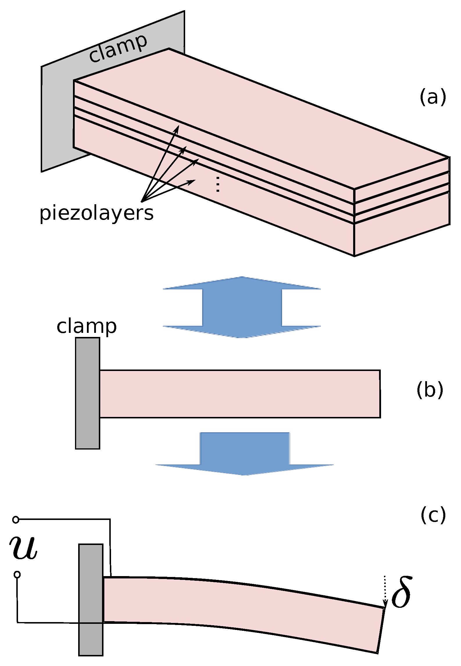
2.1. PEA Principle
2.2. PEA Linear Modeling
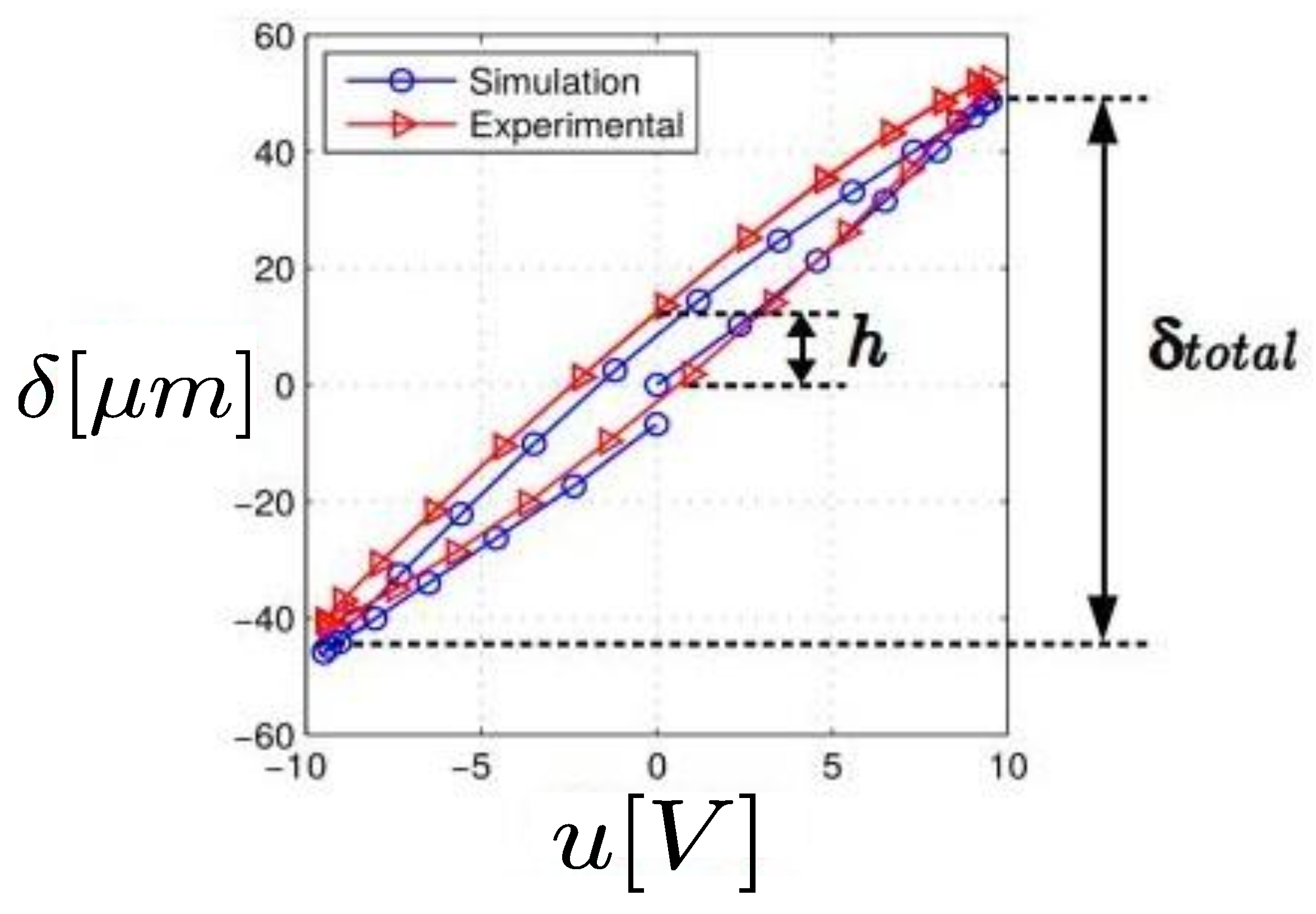
2.3. PEA Nonlinear Modeling
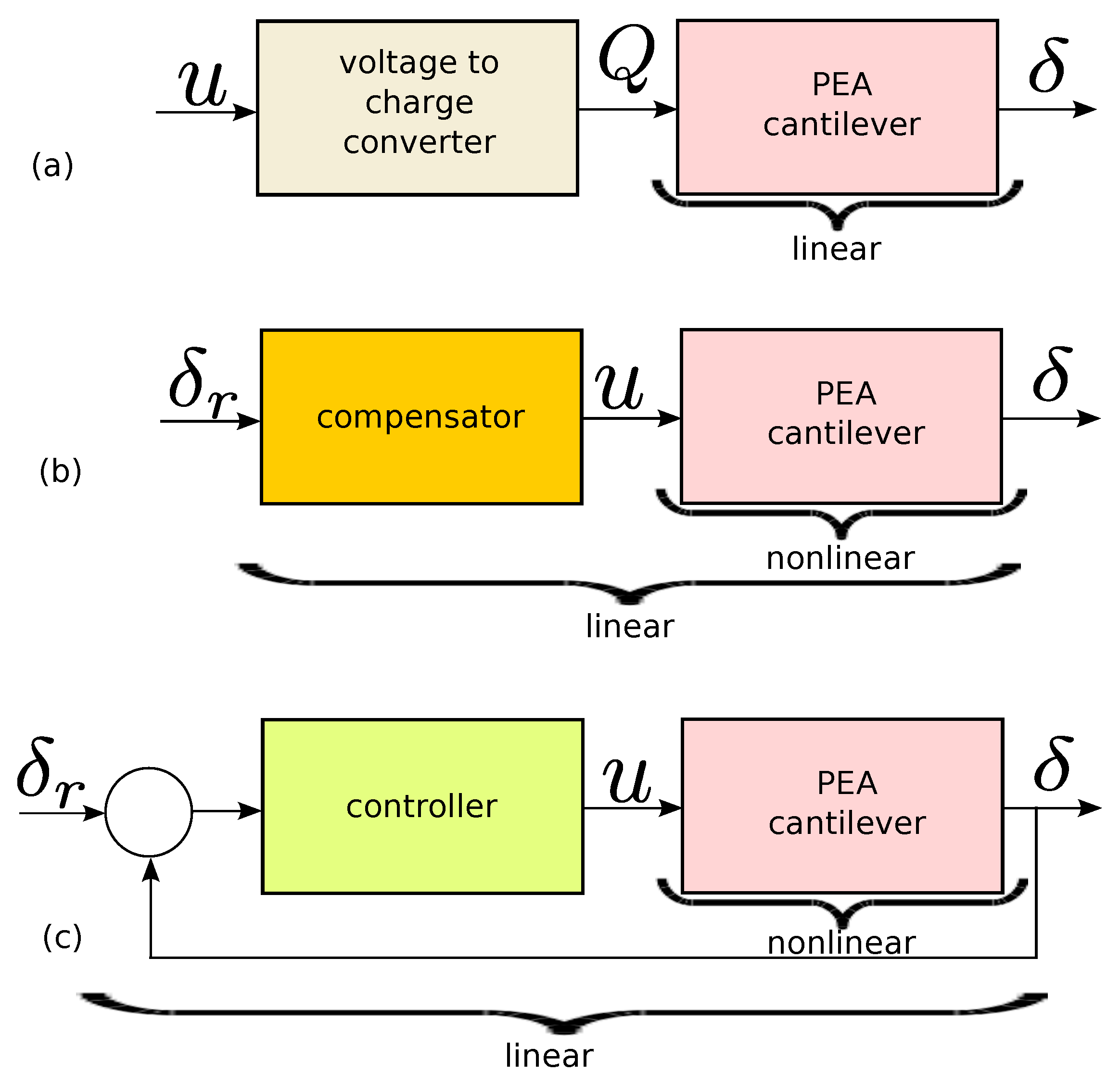
2.4. PEA Control
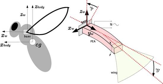
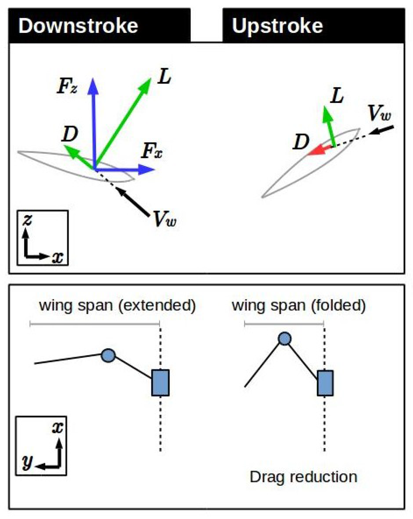
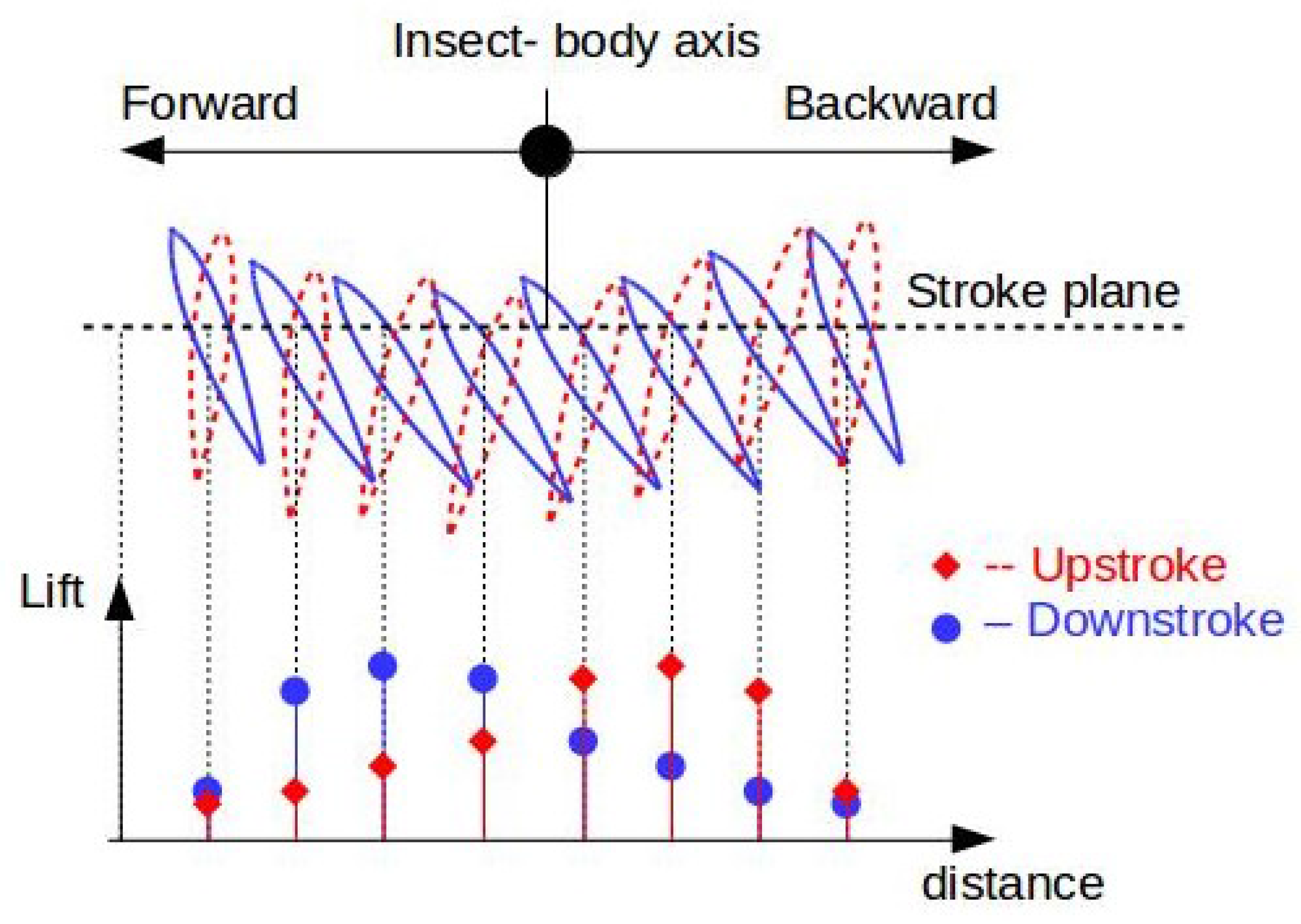
3. Aerodynamics of Basic Flapping-Wing Systems
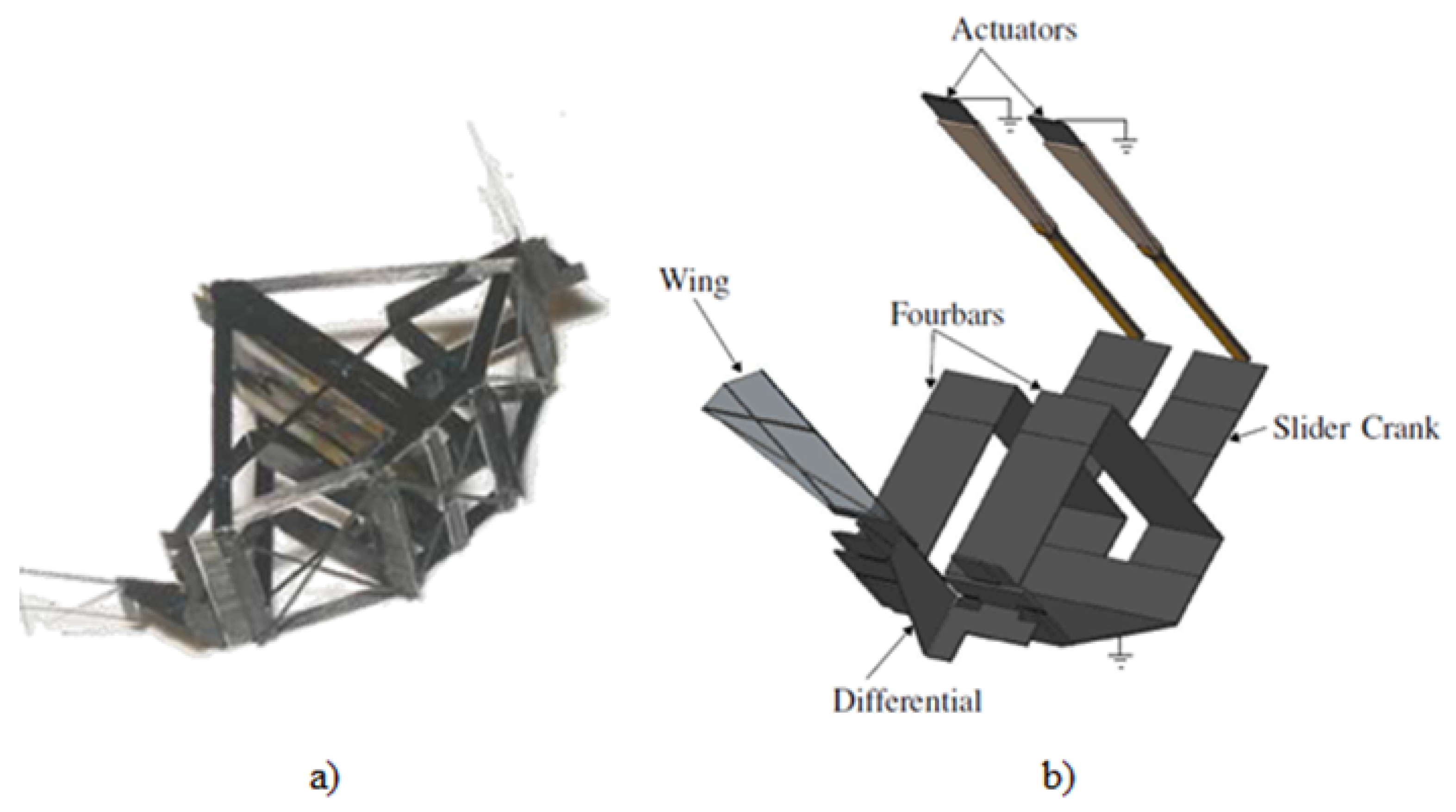
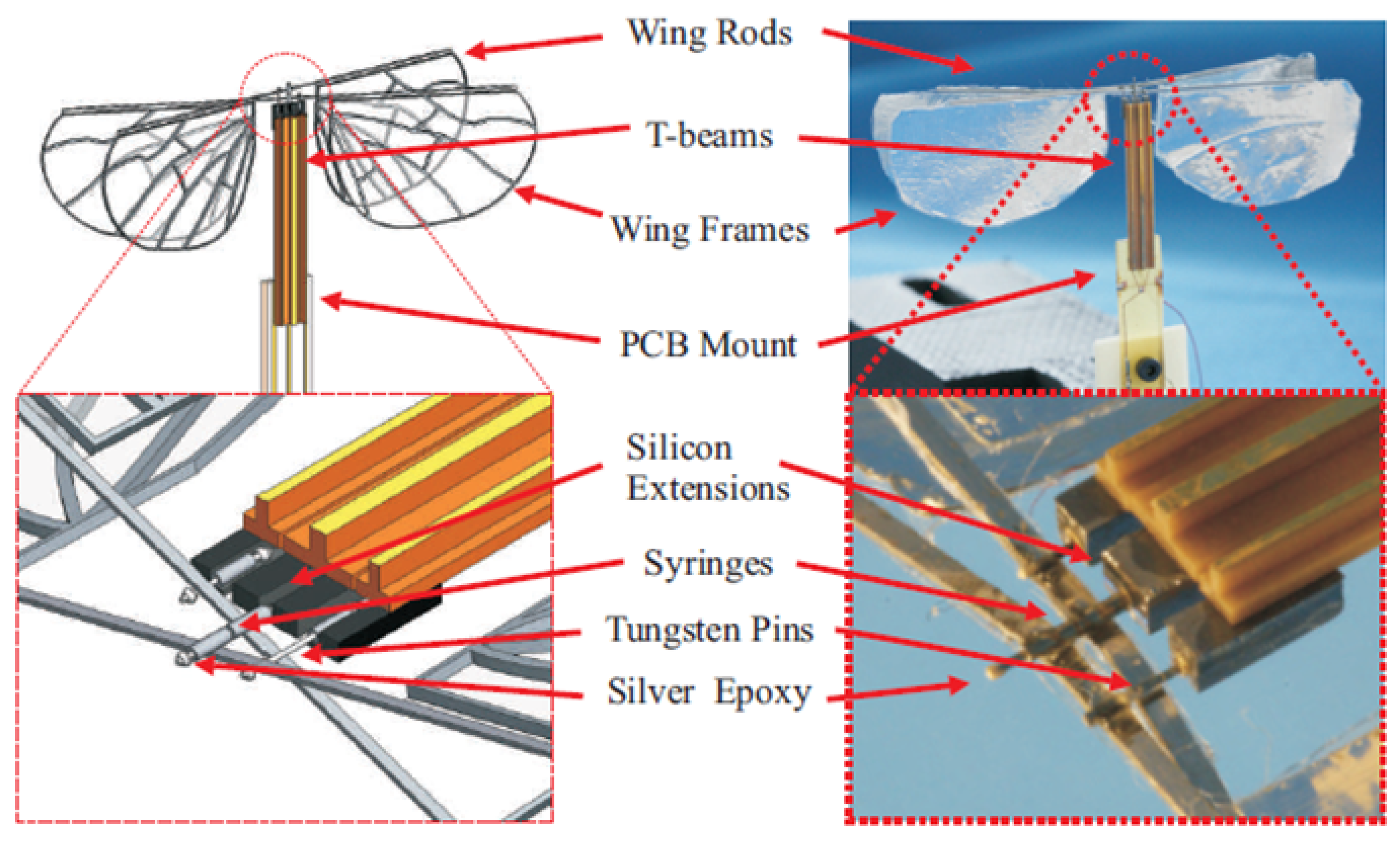
4. Current PEA-Based for Flapping-Wing MAVs
5. Concluding Remarks and Open Questions
Acknowledgments
Author Contributions
Conflicts of Interest
References
- Eisenbeiss, H. A Mini Unmanned Aerial Vehicle (UAV): System overview and image acquisition. In Proceedings of the International Workshop on Processing and Visualization Using High-Resolution Imagery, Pitsanulok, Thailand, 18–20 November 2004.
- Rahn, C.; Tadigadapa, S. High Performance Piezoelectric Actuators and Wings for Nano Air Vehicles (NAVs); Pennsylvania State University: State College, PA, USA, 2012. [Google Scholar]
- Wood, R.; Nagpal, R.; Wei, G.Y. Flight of the Robobees. Available online: http://www.scientificamerican.com/article/robobee-project-building-flying-robots-insect-size/ (accessed on 12 May 2016).
- Ballas, R.G. Piezoelectric Multilayer Beam Bending Actuators: Static and Dynamic Behavior and Aspects of Sensor Integration; Springer: Berlin, Germany, 2007. [Google Scholar]
- Rakotondrabe, M. Piezoelectric Cantilevered Structures: Modeling Control and Measurement/Estimation Aspects; Springer-Verlag: Berlin, Germany, Monography in preparation.
- Rakotondrabe, M. Smart Materials-Based Actuators at the Micro/Nano-Scale: Characterization, Control and Applications; Springer-Verlag: New York, NY, USA, 2013. [Google Scholar]
- Rakotondrabe, M. Piezoelectric Systems for Precise and High Dynamic Positioning: Design, Modeling, Estimation and Control. “Habilitation à diriger la recherche (HDR)” Dissertation, University of Franche-Comté/FEMTO-ST, Besançon, France, 2014. [Google Scholar]
- Rakotondrabe, M.; Haddab, Y.; Lutz, P. Quadrilateral modelling and robust control of a nonlinear piezoelectric cantilever. IEEE Trans. Control Syst. Technol. 2009, 17, 528–539. [Google Scholar] [CrossRef] [Green Version]
- Rakotondrabe, M. Modeling and Compensation of Multivariable Creep in multi-DOF Piezoelectric Actuators. In Proceedings of the IEEE International Conference on Robotics and Automation, St. Paul, MN, USA, 14 May 2012; pp. 4577–4581.
- Croft, D.; Shed, G.; Devasia, S. Creep, hysteresis and vibration compensation for piezoactuators: Atomic force microscopy application. ASME J. Dynamic Syst. Meas. Control 2001, 123, 35–43. [Google Scholar] [CrossRef]
- Habineza, D.; Rakotondrabe, M.; Le Gorrec, Y. Characterization, Modeling and H-inf Control of n-DOF Piezoelectric Actuators: Application to a 3-DOF Precise Positioner. Asian J. Control 2016, 18, 1–20. [Google Scholar]
- Rakotondrabe, M. Combining self-sensing with an Unkown-Input-Observer to estimate the displacement, the force and the state in piezoelectric cantilevered actuator. In Proceedings of the American Control Conference, Washington, DC, USA, 18 June 2013; pp. 4523–4530.
- Trenchant, V.; Rakotondrabe, M.; Haddab, Y. Force estimation in a 2-DOF piezoelectric actuator by using the inverse-dynamics based unknown input observer technique. Proc. SPIE 2015, 9494. [Google Scholar] [CrossRef]
- Rakotondrabe, M.; Lutz, P. Force estimation in a piezoelectric cantilever using the inverse-dynamics-based UIO technique. In Proceedings of the IEEE International Conference on Robotics and Automation, Kobe, Japan, 12–17 May 2009; pp. 2205–2210.
- Rakotondrabe, M.; Haddab, Y.; Lutz, P. Nonlinear modelling and estimation of force in a piezoelectric cantilever. In Proceedings of the IEEE/ASME International Conference on Advanced Intelligent Mechatronics, Zurich, Switzerland, 5 September 2007.
- Aljanaideh, O.; Habineza, D.; Rakotondrabe, M.; Al Janaideh, M. Experimental comparison of rate-dependent hysteresis models in characterizing and compensating hysteresis of piezoelectric tube actuators. Phys. B Condens. Matter 2015. [Google Scholar] [CrossRef]
- Aljanaideh, O.; Al Janaideh, M.; Rakotondrabe, M. Enhancement of Micro-positioning Accuracy of a Piezoelectric Positioner by Suppressing the Rate-Dependant Hysteresis Nonlinearities. In Proceedings of the IEEE/ASME International Conference on Advanced Intelligent Mechatronics, Besançon, France, 10 July 2014; pp. 1683–1688.
- Ang, W.; Kholsa, P.; Riviere, C. Feedforward controller with inverse rate-dependent model for piezoelectric actuators in trajectory-tracking applications. IEEE/ASME Trans. Mechatron. 2007, 12, 134–142. [Google Scholar] [CrossRef]
- Al Janaideh, M.; Krejci, P. Inverse rate-dependent prandtl-ishlinskii model for feedforward compensation of hysteresis in a piezomicropositioning actuator. IEEE/ASME Trans. Mechatron. 2013, 18, 1498–1507. [Google Scholar] [CrossRef]
- Rakotondrabe, M. Classical Prandtl-Ishlinskii modeling and inverse multiplicative structure to compensate hysteresis in piezoactuators. In Proceedings of the American Control Conference, Montréal, QC, Canada, 27 June 2012; pp. 1646–1651.
- Rakotondrabe, M.; Clevy, C.; Lutz, P. Complete open loop control of hysteretic, creeped, and oscillating piezoelectric cantilevers. IEEE Trans. Autom. Sci. Eng. 2010, 7, 440–450. [Google Scholar] [CrossRef] [Green Version]
- Hughes, D.; Wen, J.T. Preisach modeling of piezoceramic and shape memory alloy hysteresis. Smart Mater. Struct. 1997, 4, 287–399. [Google Scholar] [CrossRef]
- Dubra, A.; Massa, J.; Paterson, C. Preisach classical and nonlinear modeling of hysteresis in piezoceramic deformable mirrors. Opt. Express 2005, 13, 9062–9070. [Google Scholar] [CrossRef] [PubMed]
- Oubellil, R.; Ryba, L.; Voda, A.; Rakotondrabe, M. Experimental model inverse-based hysteresis compensation on a piezoelectric actuator. In Proceedings of the IEEE International Conference on System Theory, Control and Computing, Cheile Gradistei-Fundata Resort, Galati, Romania, 14 October 2015; pp. 186–191.
- Rakotondrabe, M. Bouc-Wen modeling and inverse multiplicative structure to compensate hysteresis nonlinearity in piezoelectric actuators. IEEE Trans. Autom. Sci. Eng. 2011, 8, 428–431. [Google Scholar] [CrossRef] [Green Version]
- Escareno, J.; Rakotondrabe, M.; Habineza, D. Backstepping-based robust-adaptive control of a nonlinear 2-DOF piezoactuator. IFAC Control Eng. Pract. 2015, 41, 57–71. [Google Scholar] [CrossRef]
- Habineza, D.; Rakotondrabe, M.; Le Gorrec, Y. Bouc-Wen Modeling and Feedforward Control of multivariable Hysteresis in Piezoelectric Systems: Application to a 3-DoF Piezotube scanner. IEEE Trans. Control Syst. Technol. 2015, 23, 1797–1806. [Google Scholar] [CrossRef]
- Habineza, D.; Rakotondrabe, M.; Le Gorrec, Y. Multivariable generalized Bouc-Wen modeling, identification and feedforward control and its application to a 2-DoF piezoelectric multimorph actuator. In Proceedings of the IFAC World Congress, Cape Town, South Africa, 29 August 2014; pp. 10952–10958.
- Rakotondrabe, M.; Haddab, Y.; Lutz, P. Plurilinear modeling and discrete µ-synthesis control of a hysteretic and creeped unimorph piezoelectric cantilever. In Proceedings of the IEEE International Conference on Automation, Robotics, Control and Vision, Grand Hyatt, Singapore, 5 December 2006; pp. 57–64.
- Comstock, R.H. Charge Control Actuators to Reduce Hysteresis Effects. U.S. Patent No. 4,263,527, 21 April 1981. [Google Scholar]
- Newcomb, C.V.; Flinn, L. Improving the linearity of piezoelectric actuators. J. Electron. Lett. 1982, 18, 442–443. [Google Scholar] [CrossRef]
- Newton, D.; Main, J.; Garcia, E. Piezoelectric actuation systems: Optimisation of driving electronics. Proc. SPIE 1996, 2717. [Google Scholar] [CrossRef]
- Agnus, J.; Chaillet, N. Dispositif de commande d’un actionneur piezoelectrique et scanner muni de ceux-ci. INPI Patent No. N FR20030000532, 23 July 2004. (In French)[Google Scholar]
- Rios, S.; Fleming, A.J. Control of Piezoelectric Benders Using a Charge Drive. In Proceedings of the International Conference on New Actuators, Bremen, Germany, 23 June 2014.
- Habineza, D.; Rakotondrabe, M.; Le Gorrec, Y. Simultaneous Suppression of Badly-Damped Vibrations and Cross-couplings in a 2-DoF piezoelectric actuator, by using Feedforward Standard H-inf approach. Proc. SPIE 2015, 9494. [Google Scholar] [CrossRef]
- Al Hamidi, Y.; Rakotondrabe, M. Multi-Mode Vibration Suppression in 2-DOF Piezoelectric Systems Using Zero Placement Input Shaping Technique. Proc. SPIE 2015, 9494. [Google Scholar] [CrossRef]
- Choi, G.S.; Kim, H.-S.; Choi, G.H. A study on position control of piezoelectric actuators. In Proceedings of the IEEE International Symposium on Industrial Electronics, Guimaraes, Portugal, 7–11 July 1997; pp. 851–855.
- Kenton, B.J.; Leang, K.K. Design and Control of a Three-Axis Serial Kinematic High-Bandwidth Nanopositioner. IEEE/ASME Trans. Mechatron. 2012, 17, 356–369. [Google Scholar] [CrossRef]
- Soltani Bozchalooi, I.; Youcef-Toumi, K. Multi-actuation and PI control: A simple recipe for high-speed and large-range atomic force microscopy. Ultramicroscopy 2014, 146, 117–124. [Google Scholar] [CrossRef] [PubMed]
- Mahmood, I.A.; Liu, K.; Moheimani, S.O.R. Two Sensor Based H-Infinity Control of a Piezoelectric Tube Scanner. In Proceedings of the IFAC World Congress, Seoul, Korea, 6–11 July 2008.
- Daniele, A.; Salapaka, S.; Salapaka, M.V.; Dahleh, M. Piezoelectric scanners for atomic force microscopes: Design of lateral sensors, identification and control. In Proceedings of the American Control Conference, San Diego, CA, USA, 2–4 June 1999; Volume 1, pp. 253–257.
- Chibum, L.; Salapaka, S.M. Robust broadband nanopositioning: Fundamental trade-offs, analysis, and design in a two-degree-of-freedom control framework. Nanotechnology 2009, 20, 035501. [Google Scholar]
- Khadraoui, S.; Rakotondrabe, M.; Lutz, P. Interval Modeling and Robust Control of Piezoelectric Microactuators. IEEE Trans. Control Sys. Technol. 2012, 20, 486–494. [Google Scholar] [CrossRef] [Green Version]
- Khadraoui, S.; Rakotondrabe, M.; Lutz, P. Combining H-inf approach and interval tools to design a low order and robust controller for systems with parametric uncertainties: Application to piezoelectric actuators. Int. J. Control 2012, 85, 251–259. [Google Scholar] [CrossRef] [Green Version]
- Khadraoui, S.; Rakotondrabe, M.; Lutz, P. Design of RST-structured controller for parametric uncertain system using interval analysis: Application to piezocantilever. Asian J. Control 2013, 15, 142–154. [Google Scholar] [CrossRef] [Green Version]
- Xu, Q.; Li, Y. Global sliding mode-based tracking control of a piezo-driven xy micropositioning stage with unmodeled hysteresis. In Proceedings of the IEEE/RSJ International Conference on Intelligent Robots and Systems, St. Louis, MO, USA, 15 November 2009.
- Yu, S.; Shirinzadeh, B.; Alici, G.; Smith, J. Sliding mode control of a piezoelectric actuator with neural network compensating rate-dependent hysteresis. In Proceedings of the IEEE International Conference on Robotics and Automation, Barcelona, Spain, 18–22 April 2005; pp. 3641–3645.
- Chen, X.; Hisayama, T. Adaptive sliding-mode position control for piezo-actuated stage. IEEE Trans. Ind. Electron. 2008, 55, 3927–3934. [Google Scholar] [CrossRef]
- Liaw, H.C.; Shirinzadeh, B.; Smith, J. Enhanced sliding mode motion tracking control of piezoelectric actuators. Sens. Actuators A Phys. 2007, 138, 194–202. [Google Scholar] [CrossRef]
- Sofla, M.S.; Rezaei, S.M.; Zareinejad, M.; Saadat, M. Hysteresis-observer based robust tracking control of piezoelectric actuators. In Proceedings of the American Control Conference, Baltimore, MD, USA, 30 June–2 July 2010; pp. 4187–4192.
- Tien, S.; Zou, Q.; Devasia, S. Iterative control of dynamics-coupling-caused errors in piezoscanners during high-speed AFM operations. IEEE Trans. Control Syst. Technol. 2005, 13, 921–931. [Google Scholar] [CrossRef]
- Rakotondrabe, M.; Rabenorosoa, K.; Agnus, J.; Chaillet, N. Robust feedforward-feedback control of a nonlinear and oscillating 2-dof piezocantilever. IEEE Trans. Autom. Sci. Eng. 2011, 8, 506–519. [Google Scholar] [CrossRef] [Green Version]
- Rakotondrabe, M.; Al Janaideh, O.; Al Janaideh, M. H-inf Control for a Smart Micro-Positioning System with an Analytical Model for the Output of the Inverse Compensation. In Proceedings of the American Control Conference, Chicago, IL, USA, 1–3 July 2015; pp. 2643–2648.
- Devasia, S.; Eleftheriou, E.E.; Moheimani, R. A survey of control issues in nanopositioning. IEEE Trans. Control Syst. Technol. 2007, 15, 802–823. [Google Scholar] [CrossRef]
- Dargent, T. Microsystème à ailes vibrantes: Utilisation des technologies MEMS pour la réalisation d’un microdrone bioinspiré. Ph.D. Thesis, Université de Valenciennes et du Hainaut-Cambresis, Famars, France, 2011. [Google Scholar]
- Ellington, C. The novel aerodynamics of insect flight: Applications to microair vehicles. J. Exp. Biol. 1999, 202, 3439–3448. [Google Scholar] [PubMed]
- Steltz, E.; Avadhanuka, S.; Fearing, R. High lift force with 275 Hz wing beat in MFI. In Proceedings of the International Conference on Intelligent Robots and Systems, San Diego, CA, USA, 29 October–2 November 2007; pp. 3987–3992.
- Chirarattananon, P.; Ma, K.Y.; Wood, R. Adaptive control for takeoff, hovering, and landing of a robotic fly. In Proceedings of the International Conference on Intelligent Robots and Systems, Tokyo, Japan, 3–7 November 2013.
- Wood, R. The first takeoff of a biologically inspired at-scale robotic insect. IEEE Trans. Robot. 2008, 24, 341–347. [Google Scholar] [CrossRef]
- Guo, S.; Li, D.; Wu, J. Theoretical and experimental study of a piezoelectric flapping wing rotor for micro aerial vehicle. Aerosp. Sci. Technol. 2011, 23, 429–438. [Google Scholar] [CrossRef]
- Hall, A.; Roberts, R.; Weintraub, I.; Riddick, J. Flapping Wing Technology for Micro Air Vehicles Incorporating a Lead Zirconate Titanate (PZT) Bimorph Actuator; U.S. Army Research Laboratory: Adelphi, MD, USA, 2012.
- Nguyen, Q.; Syaifuddin, M.; Park, H.; Byun, D.; Goo, N.; Yoon, K. Characteristics of an Insect-mimicking Flapping System Actuated by a Unimorph Piezoceramic Actuator. J. Intell. Mater. Syst. Struct. 2008, 19, 1185–1193. [Google Scholar] [CrossRef]
- Nguyen, Q.; Park, H.; Goo, N.; Byun, D. Aerodynamic force generation of an insect-inspired flapper actuated by a compressed unimorph actuator. Chin. Sci. Bull. 2009, 54, 2871–2879. [Google Scholar] [CrossRef]
- Truong, Q.; Nguyen, Q.; Park, H.; Byun, D.; Goo, N. Modification of a Four-Bar Linkage System for a Higher Optimal Flapping Frequency. J. Intell. Mater. Syst. Struct. 2011, 22, 59–66. [Google Scholar] [CrossRef]
- Gendreau, D.; Rougeot, P.; Mohand-Ousaid, A.; Rakotondrabe, M. 3D-Printing: A promising technology to design three-dimensional microsystems. In Proceedings of the International Conference on Manipulation, Automation and Robotics at Small Scales, Paris, France, 18–22 July 2016.
- Mohand-Ousaid, A.; Gendreau, D.; Rougeot, P.; Rakotondrabe, M. Design, static modeling and simulation of a 5-DOF precise piezoelectric positioner. In Proceedings of the SPIE Sensing Technology + Applications: Sensors for Next Generation Robots Conference, Baltimore, MD, USA, 21 April 2016.
- Khadraoui, S.; Rakotondrabe, M.; Lutz, P. Optimal design of piezoelectric cantilevered actuators with guaranteed performances by using interval techniques. IEEE/ASME Trans. Mechatron. 2014, 19, 1660–1668. [Google Scholar]
- Rakotondrabe, M.; Khadraoui, S. Design of Piezoelectric Actuators with Guaranteed Performances using the Performances Inclusion Theorem and Interval Tools. In Smart Materials-Based Actuators at the Micro/Nano-Scale: Characterization, Control and Applications; Rakotondrabe, M., Ed.; Springer-Verlag: New York, NY, USA, 2013. [Google Scholar]
- Rakotondrabe, M. Performances inclusion for stable interval systems. In Proceedings of the American Control Conference, San Francisco, CA, USA, 30 June 2011; pp. 4367–4372.
- Bienaime, A.; Chalvet, V.; Clevy, C.; Gauthier-Manuel, L.; Baron, T.; Rakotondrabe, M. Static/dynamic trade-off performance of PZT thickfilm micro-actuators. J. Micromech. Microeng. 2015, 25, 075017. [Google Scholar] [CrossRef]
- Chalvet, V.; Habineza, D.; Rakotondrabe, M.; Clevy, C. Hysteresis characterization of novel thick-film PZT microactuators. Phys. B Condens. Matter 2015. [Google Scholar] [CrossRef] [Green Version]


| Model | Size | Actuator | Control | Beat Frequency | Lift/Thrust Generated | Other Features |
|---|---|---|---|---|---|---|
| [57] | 25 mm (wingtip to wingtip) | Unimorph piezoelectric bending actuators | Feedback Control | 275 Hz | L: 1400 µN | Piezoelectric actuator stiffness 400 N/m. |
| [58] | 30 mm wingspan | Bimorph piezoelectric clamped-free bending cantilever | Adaptive Control | 120 Hz | T > 1.3 mN | 80 mg FW using Smart Composite Microstructures (SCM) process |
| [2] | 37.5 mm wingspan | Piezoelectric T-beams | - | 25.5 Hz | T: 1.34 mN | - |
| [60] | 90 mm wingspan | Piezoelectric THUNDER TH-8R | - | 125 Hz | L: 5.35 mN | - |
| [61] | - | Bimorph Piezoelectric and a Functionally Modified Bimorph (FMB) | - | 21 Hz | L: 10 mN | Flapping angle of 45 |
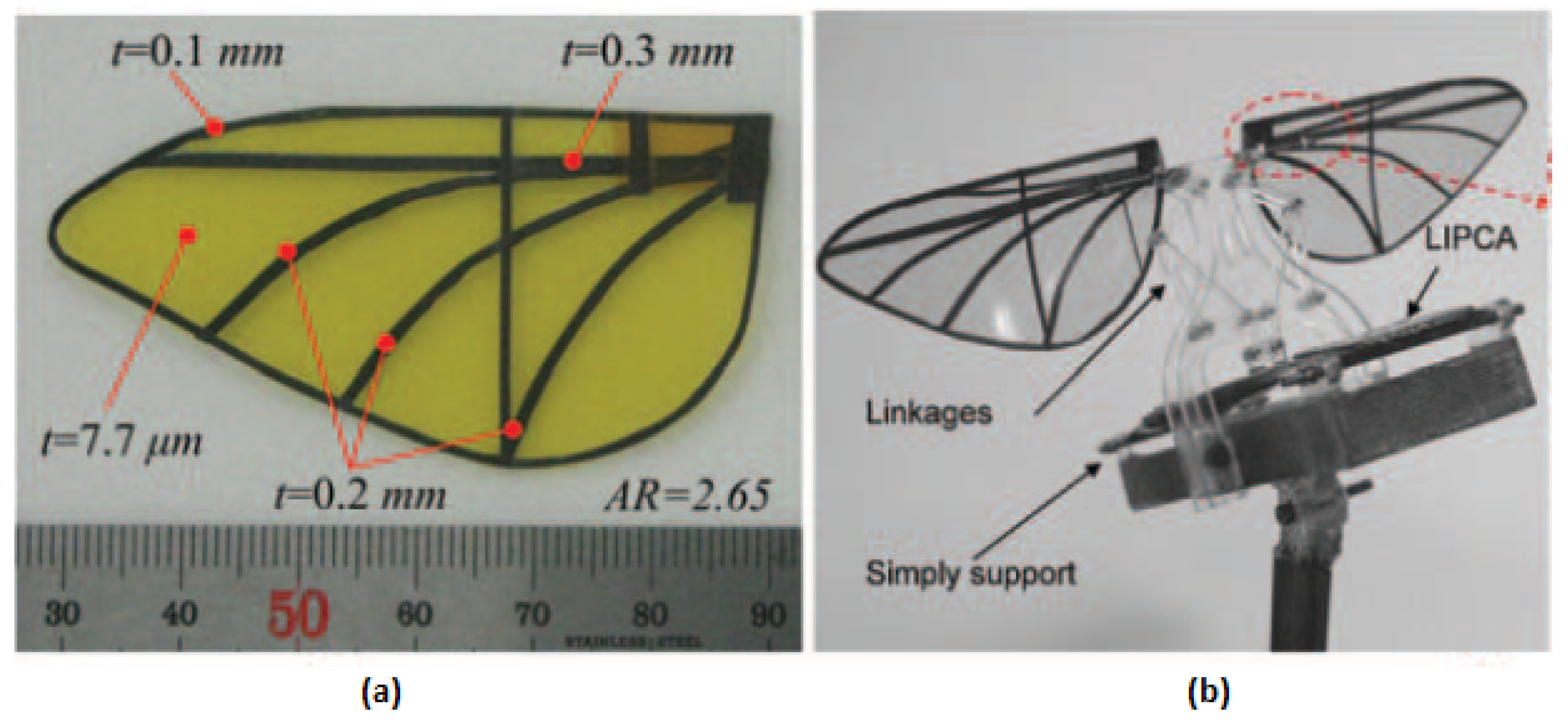
| [62,63,64] | - | Unimorph Piezoceramic, Lightweight Piezocomposite actuator (LIPCA) | - | 17 Hz | - | Flapping angle of 92 |
© 2016 by the authors; licensee MDPI, Basel, Switzerland. This article is an open access article distributed under the terms and conditions of the Creative Commons Attribution (CC-BY) license (http://creativecommons.org/licenses/by/4.0/).
Share and Cite
Durán, J.C.; Escareno, J.A.; Etcheverry, G.; Rakotondrabe, M. Getting Started with PEAs-Based Flapping-Wing Mechanisms for Micro Aerial Systems. Actuators 2016, 5, 14. https://doi.org/10.3390/act5020014
Durán JC, Escareno JA, Etcheverry G, Rakotondrabe M. Getting Started with PEAs-Based Flapping-Wing Mechanisms for Micro Aerial Systems. Actuators. 2016; 5(2):14. https://doi.org/10.3390/act5020014
Chicago/Turabian StyleDurán, J. Carlos, Juan Antonio Escareno, Gibran Etcheverry, and Micky Rakotondrabe. 2016. "Getting Started with PEAs-Based Flapping-Wing Mechanisms for Micro Aerial Systems" Actuators 5, no. 2: 14. https://doi.org/10.3390/act5020014