1. Introduction
Nowadays robots are still mostly used in industrial environments to perform tedious and repetitive tasks autonomously such as holding, moving and assembling parts [
1]. Welding of a car body in the automotive industry or handling and packaging electronic components or food are good examples. Such industrial robots are position controlled, with focus on precision and repeatability regardless of external perturbations, even if some level of force control is also required for assembly tasks. This approach is, however, only useful for mass production as it requires the whole factory, or at least the whole assembly line, to be organized around the robots which must work in a controlled environment, the human having to stay away for productivity and safety reasons. Many tasks do not comply with these requirements. Indeed, numerous activities involve complex and non-repetitive tasks which are still performed manually. Such tasks cannot be robotized as it would require expensive solutions which, for small series production, are not competitive compared to human workers, especially in low wage countries. For some tasks requiring reactivity and adaptability, no solution even exist as, despite continuous advancements in sensors and artificial intelligence, humans have unmatched sensing, analysis and decision capabilities.
Recently, new robots called collaborative robots or cobots have been introduced to address specifically such tasks and environments. Cobots are usually equipped with a handle grasped in hand and used to manipulate the robot, some of them even allowing to grasp and move any of their links. This way, they perform tasks under direct manual control of humans who keep a permanent control on task advancement. Yet they help operators either through guiding their gesture when performing a complex or precise operation or through power amplification in arduous or heavy load tasks. They combine the human awareness and reactivity and the robot working force. They come in different forms, ranging from simple electro-mechanical assistive systems [
2,
3], to robots either equipped with dedicated handles [
4] or specifically designed to interact with humans [
5,
6,
7], to more complex systems such as exoskeletons [
8,
9,
10]. It is worth noting that even if cobots have initially been developed for permanent interaction with humans, most of them available on the market today like the UR3, UR5 and UR10 from Universal Robots (Odense, Denmark,
http://www.universal-robots.com/), LBR IIWA from Kuka (Augsburg, Germany,
http://www.kuka-robotics.com/), or Baxter from Rethink Robotics (Boston, MA, USA,
http://www.rethinkrobotics.com/) are mainly used to perform industrial applications autonomously just as conventional robots do. The opportunity to work in close cooperation with them and to move them manually is only used from time to time to program their trajectories in space. In this approach, the user moves the robot to different points in space. Then, the robot’s controller generates a trajectory passing through these points, allowing the robot to subsequently reproduce autonomously the same trajectory. Alternative and more complex programming by demonstration techniques allow learning complex trajectories instead of only passing points [
11]. In any case, in this way cobots can be programmed very easily and quickly and can be used for small batch production. A comprehensive review of cobots working this way can be found in [
12].
Other examples of physical human-robot collaboration are found in force feedback teleoperation [
13,
14,
15] and haptics for Virtual Reality (VR) [
16,
17,
18]. Teleoperation systems are composed of a master arm equipped with a handle grasped in hand and manipulated by an operator, and a slave robot, located in a remote environment, which mimics the movements of the master arm. This way, the user is able to control the movements of the robot in the distant site which he cannot physically access because this site is hazardous (e.g., nuclear teleoperation, space telerobotics), distant, or at a different scale (e.g., telesurgery, tele micromanipulation). In force feedback systems, the master arm is further equipped with motors which are controlled either to follow the slave robot’s movements, or to apply forces similar to those applied on the slave arm and sensed with adequate sensors. This way, the operator is able to feel the interactions of the slave robot with its environment and can work more precisely, more quickly, and with less force, at the price of more complexity and potential instabilities if the gains in the controller of the master slave coupled system are improperly adjusted. The same principle is used in VR haptics, the slave robot being replaced with an avatar in a simulated environment. The user manipulates a haptic interface usually equipped with a handle whose movements are reproduced by a virtual avatar. A physical engine is used to compute, in real-time, the forces applied on the avatar; for example, simulated gravity or forces applied by the surrounding objects if collisions with the environment occur, and its dynamics. Finally, the haptic interface actuators are used to move the handle according to the avatar’s movements or to reproduce the forces applied on it. VR haptics can be used, for example, to simulate assembly tasks and verify that the different parts of a complex system being designed can be assembled together. This approach allows quicker detection of clashes and faster settlement of errors compared to real prototypes. As the human behavior can be simulated as well, VR systems can also be used to design workshops, assembly lines, or dexterous tasks in a complex environment and check their ergonomics.
It is worth noting that whether considering telerobotics, telesurgery, or VR haptics, force feedback interfaces share the same design drivers. First of all, contrary to usual industrial robots, all of these systems are force controlled. Additionally, they must be as transparent as possible, i.e., they must resist the user’s movements as little as possible in free space. They must, therefore, have a sufficiently large workspace and exhibit low friction and low inertia. They must also have high dynamics in order to apply sufficiently rapidly rising forces when the slave robot or avatar encounters obstacles. The later calls in particular for a sufficient mechanical stiffness and high controller gains, also felt by the operator as a high control stiffness. Finally, being in close contact with the operator, they must be safe and stable in any conditions. These requirements also hold for cobots, which can be seen as collocated master slave systems and also belong to the field of interactive robotics. Their friction and inertia must be low enough to allow free movements of the operator over a large workspace when no guidance is desired. Yet their force capacity and stiffness must be high enough to clearly guide the user when needed, especially in case a permanent force is already applied; for example, to carry an object if its weight is not completely compensated by the robot.
In this paper, we introduce a new reducer called a differential cable drive which tries to answer these requirements. It is highly backdrivable, it has a high efficiency, and its component’s dimensions can be tuned to obtain any reduction ratio using only simple and inexpensive components.
This paper is organized as follows.
Section 2 presents a short review of the existing actuators and sensors usually used in the field of interactive robotics, highlighting their advantages and drawbacks. Then,
Section 3 introduces the principle of operation, design and dimensioning of the differential cable drive. A 1-DOF (degree of freedom) prototype robot integrating such a reducer it then presented in
Section 4 and its performances are given and discussed in
Section 5. Finally,
Section 6 concludes this paper.
2. State of the Art in Interactive Robotics Actuation
Several solutions have been introduced in the literature to answer the requirements of interactive robotics, i.e., a high mechanical transparency, high dynamics, and a high degree of safety. One can globally distinguish three main approaches: development of mechanically highly backdrivable actuators, adaptation of existing robots to give them some interactive capabilities, and development of fully integrated mechatronic solutions. These approaches are introduced and discussed in the following subsections.
2.1. Highly Backdrivable Actuators
Specific actuation systems have been developed for teleoperation. Indeed, permanent human system collaboration is a key characteristic in this field. Historically, the first master slave systems were purely mechanical devices developed for remote handling in the nuclear industry [
13]. The master and slave arms were mechanically bounded together and the master arm’s handle was coupled to the slave gripper using cables, pulleys and rods routed through the poly-articulated structure. The mechanical coupling was made at the joint level, which means that every joint of the slave robot reproduced the movements of the corresponding joint of the master arm and
vice versa. Such systems are very efficient and force feedback is of a remarkable quality. They are still routinely used today as the standard solution for remote handling in nuclear facilities. However, the operator has to stay close to the radiation-hardened wall separating the master side from the slave side in which the radioactive material is manipulated and, more specifically, close to the small hardened window giving a visual access to the site, hence awkward and uncomfortable postures. Direct mechanical joint coupling also imposes large movements and high forces on the operator side when large displacements and large forces are required in the remote environment. To overcome this problem, master and slave robots were separated and actuated with backdrivable high-efficiency actuators first still coupled at the joint level [
19], then coupled in the Cartesian space. Such force feedback systems allow introducing position and force ratios between the master and slave robots. Later on, more advanced functions were introduced as, for example, carried objects’ weight compensation, clutching, virtual guides, virtual or augmented reality visual feedback,
etc. Master slave systems are also used in space telerobotics, telesurgery or VR (the slave being replaced with a virtual avatar in the later case). Being derived from passive systems which had to be as mechanically transparent as possible, most of the master arms for teleoperation and haptic interfaces for VR still make use of mechanically transparent, backdrivable, and high-efficiency actuators and reducers. This way, the force applied on the different links is roughly proportional to the motors currents and theses robots can be force controlled without force sensors using more simple control loops.
Some of the first force feedback robots used block-and-tackle reducers, in which a cable is routed around multiple pulleys arranged in a fixed group and a moving group. This way, the movement of the moving group of pulleys used as reducer output is only a fraction of the cable movement used as input. By attaching two antagonistic cables to the motor and using two moving groups with a large number of pulleys to pull two output cables driving a joint pulley, a relatively large reduction ratio can be obtained. Indeed such a reducer is a usual solution on cranes with, however, only one input and one output cable in this case. In master slave systems, the input cables usually used with such reducers were further replaced with metallic tapes [
19], allowing for a higher stiffness and a more compact design. These reducers have exceptional performances in terms of reversibility, friction, stiffness, and inertia. However, they require a complex arrangement of numerous moving parts and they are bulky.
Cable capstan drives are also widely used on master-slave systems and haptic interfaces [
16,
20,
21,
22,
23,
24]. They are composed of a first small input pulley attached to the motor axis, a cable wound on this pulley, and attached at both ends to a second larger output pulley fixed on the driven link. The friction between the cable and pulley being an exponential function of the winding angle, it does not slide on the input pulley, provided a sufficient number of turns. Cable capstan reducers function like gears, the gear teeth being replaced with the transmission cable. Their reduction ratio is directly proportional to the ratio between the diameters of the input and output pulleys. Yet, while gear trains display either backlash or friction, capstan reducers have zero backlash and a negligible friction. They are, thus, highly transparent, backdrivable, and have a very high efficiency, which make them very well suited for interactive robotics. However, the cable deforms plastically when bent too narrowly. As a consequence, the input pulley must respect a minimum diameter, typically in the order of 10 mm for most often-used multiple-strand miniature metal cables. Large reduction ratios thus require large output pulleys and, in practice, cable capstan reducers suffer from a limited reduction ratio, usually in the order of 10:1 to 20:1. Furthermore, contrary to belts, cables have to be wrapped in spirals around the input pulleys. As a consequence, they advance along the axis of these pulleys as the joint moves. For large angles of rotation and/or large reduction ratios, this advancement is not negligible and input pulleys are relatively long. As the cable must always exit the driving pulley in front of the entry on the driven pulley, the later must have the same width as the former and the system is globally cumbersome in this case. Of course these difficulties can be circumvented using two-stage cable reducers [
5] or combining cable reducers and other reduction means; for example, friction drives as in [
25]. These solutions, however, increase complexity. It is worth noting that two-stage timing belt reducers have also been used recently for the design of a balance feedback interface [
26]. The reduction ratio is however limited to 23:1.
Another solution used on master arms and exoskeletons is screw and cable actuators (SCS) [
27]. These actuators make use of a ball screw whose nut is used as an input driven by an actuator, usually through a first belt reduction stage, and whose screw is attached to both ends of a cable, itself attached to an output pulley. By drilling the screw and attaching the cable ends close to the center of the screw and close to the nut, parasitic efforts and movements in the system are minimized and efficiency maximized. Such an actuator is compact, highly backdriveable, and has a high efficiency. Moreover, contrary to gears and capstan drives, the actuator is parallel to the screw. This way, a slender design, particularly well suited for integration on slim robots and exoskeletons, can be obtained. Additionally, having two stages, SCS can reach relatively high reduction ratios, typically on the order of 60:1 to 80:1. They however make use of complex and expensive components. Furthermore, as the screw must be drilled to allow attaching the cable near its center, large screws are required. This requires, in turn, large nuts which introduce additional inertia.
2.2. Adaptation of Industrial Robots to Interactive Robotics Requirements
The main drawback of highly backdriveable actuators found in teleoperation and VR haptics is their bulkiness when a large reduction ratio is required, complexity, and cost. On the contrary, industrial robots’ actuators are relatively compact and cost-effective. As previously said, such robots are, nowadays, routinely used in many domains. They are efficient and reliable. Their main drawback when considering interactive robotics is that they are usually position controlled and insensitive to external perturbations, especially interactions with users. To solve this problem, it is possible to equip such robots with six-axes force sensors.
In case of a teleoperation slave robot, a single sensor placed either between the ground and the robot basis or between the robot and the tool is required [
28]. This way, the friction of the robot can be compensated, as well as part of its inertia. This approach proves its efficiency. Indeed, reconditioned industrial robots have been successfully used for maintenance operations in the nuclear industry [
29]. It is cost-effective (when the electronic can sustain the doserate), as industrial robots are mass produced at a reasonable cost. However, industrial robots remain dangerous and this solution cannot be applied on the master side.
In case of a cobot, two sensors are required, the second one inserted between the robot and the handle grasped by the operator [
30]. This way, both the force applied by the operator and by the tool can be sensed and controlled. The advantages and drawbacks of industrial robots used for cobotics are the same as for telerobotics. However, if the slave robot can be remotely controlled, this is not the case for a cobot which is always close to the operator. Hence, safety issues are or primary importance in this case and in practice, industrial robots used as cobots are placed in cages guarantying a safety zone which is only accessible through holes allowing to grasp a handle but preventing from any torso or head collision with the robot. This solution is not human-friendly and clearly not the best one for such applications
2.3. Development of Fully Integrated Mechatronic Solutions
Highly backdriveable actuators being bulky, and industrial robots raising safety issues, specific mechatronic systems were developed to answer the previously mentioned requirements.
A first class of interactive robots makes use of solutions initially developed for high performance autonomous robots. As an example, the LBR IIWA from Kuka and Sawyer from Rethink Robotics use light links driven by partially backdriveable actuators and harmonic drive reducers, whose friction and inertia are low. Friction is further compensated at the joint level thanks to one-axis joint force or torque sensors. These robots are much lighter than industrial robots. Some of them like the LBR IIWA are indeed derived from space robotics technologies for which low weight is paramount [
31]. Furthermore, being torque controlled at the joint level, they can sense the force applied on any link and any link can be equally grasped and displaced by the operator. Globally, they are much safer than industrial robots [
32] and can be used both as haptic interfaces [
33] or cobots [
6]. However, harmonic drive reducers have a limited efficiency and transparency compared to cable drives and a low quality force rendering, both considering feedback and guidance.
Another solution used for example on the Baxter robot from Rethink Robotics is to introduce elastic elements between the actuators and links of the robot. Such actuators, called series elastic actuators [
34], have the advantage of lower reflected inertia and more stable force control, at the price however of lower apparent stiffness and, hence, a less precise guidance of the user’s gestures. This drawback can be cancelled using variable stiffness actuators and/or antagonistic actuation [
35], at the price, however, of an increased complexity. Lower quality force rendering or gesture guidance are not prohibitive for robots like LBR IIWA, Baxter, and Sawyer, which are manipulated only from time to time for programming by demonstration purposes, as such robots are working autonomously most of the time, as explained above. It is, however, not the best solution for robots working in permanent collaboration with humans.
2.4. Summary of the Advantages and Drawbacks of Existing Actuation Systems for Interactive Robotics
As highlighted above, several solutions exist for giving robots interactive capabilities. First of all, it is possible to equip existing industrial robots with force sensors to render them sensitive to external forces applied by an operator. This solution is, however, not well suited for master arms, haptic interfaces, and cobots, as industrial robots remain dangerous due to their large force capacity, high speed, large inertia, and highly rigid links. As a consequence, they have to be physically separated from the user. A second approach proposed in the literature is to use lighter and less powerful lightweight robots using either harmonic drive reducers or series elastic actuators. Their maximum speed and force capacity are lower, and their joints are more compliant. All of these characteristics make them more human-friendly and allow using them close to human operators. However, their limited transparency, considering either friction or stiffness, leads to a limited quality force rendering and/or user guidance. This is not a real problem for robots with which humans interact only from time to time to program them by demonstration. It is, however, a real limitation for robots working in permanent collaboration with humans, as for example exoskeletons or haptic interfaces. For those robots, mechanically highly backdrivable actuators developed for teleoperation and VR haptics appear as the best solution. Their main drawback is their bulkiness when a large reduction ratio is required, complexity and cost. The purpose of this paper is to introduce a new reducer called a differential cable drive which circumvents these drawbacks. This reducer is presented in the next sections.
3. Design and Dimensioning of a Bi-Directional Differential Cable Drive Actuator
3.1. Genesis
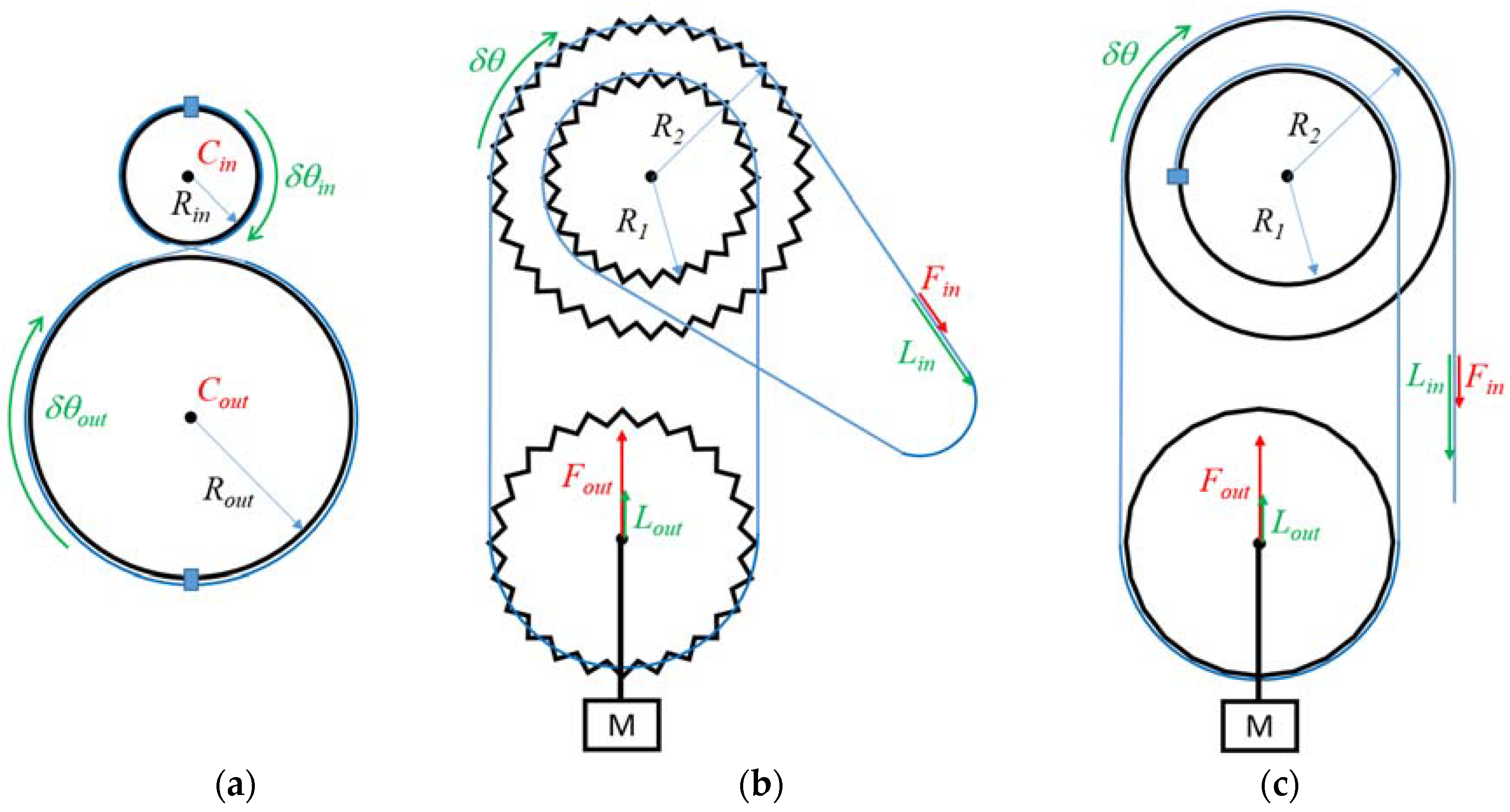
Among the mechanically highly backdrivable reducers found in the literature, the cable capstan drive is of particular interest. It is much simpler and less bulky than block-and-tackle reducers and does not make use of complex mechanical parts as screw and cable actuators do. Its principle of operation, described in
Section 2.1, is further detailed hereunder, with respect to
Figure 1a. A cable is wound and fixed on the input and output pulleys whose radii are equal to
and
(measured at the level of the neutral fiber of the cable). When the input pulley is rotated through an angle
, the output pulley rotates through an angle
equal to:
The reduction ratio (
) is thus equal to:
Cable capstan drives are well suited for interactive robotics. They are highly transparent, they are backdrivable, and they have a very high efficiency. They are, however, relatively cumbersome when a high reduction ratio is required, as in practice the diameter of the input pulley cannot be smaller than a lower limit under which metal cables usually used on such reducers deforms plastically when wound around the pulley. As a consequence, a large output pulley is required when a high reduction ratio is desired.
Another interesting mechanism found in the literature is the Weston’s differential pulley block illustrated by
Figure 1b. In this mechanism, a chain is pulled at an input end, is wound around a first chainring of radius
, passes around an output chainring, is wound around a second chainring of radius
rigidly attached to the first one (with
slightly larger than
), and finally goes back to the input end. If a user pulls the chain with a force
(see
Figure 1b), both first and second chainrings turn clockwise of an angle
. As a consequence, the cable unwinds from the first chainring of a length equal to
and winds around the second chainring of a length equal to
, and the output pulley is lifted from a distance equal to half to difference, that is,
. The corresponding distance travelled at the input end being
, we get:
The reduction ratio (
) is, thus, equal to:
Given a small difference between the radii of the chainrings, a very high reduction ratio can be obtained. Weston differential pulleys are indeed commonly used on manual chain hoists to lift very heavy objects, like car engines. With chains, however, the chainrings’ radii are linked with the number of teeth and cannot be chosen arbitrarily (the difference is usually one or a few teeth). Also, chainrings cannot be made very small and the system is relatively cumbersome. While this is not a problem for workshops’ hoists, it is not convenient for a robotic reducer.
Similar systems using cables instead of chains also exist (see
Figure 1c). Such mechanisms, making use of a differential pulley, are commonly used for the purpose of teaching the theory of machines (see for example the wheel and differential axle proposed by P.A. Hilton Ltd, Stockbridge, UK,
http//www.p-a-hilton.co.uk/). The principle of operation and the reduction ratio are the same as for the Weston’s differential pulley block. With a cable instead of a chain, however, the radii can be chosen arbitrarily close to each other, thus an even higher reduction ratio can be obtained. It is worth noting that, contrary to the cable capstan drive, the bulkiness of the system is independent of the reduction ratio, hence a potentially more compact solution when a high reduction ratio is required. Additionally, this mechanism remains highly transparent and backdrivable. However, in its current form, is can only pull an output load (mass M on
Figure 1c) in one direction. This is not convenient for a robot’s joint which moves in opposite directions.
In this paper, we propose to combine two properly-synchronized input differential pulleys with an output pulley similar to a cable capstan drive’s one to control a robot joint. The principle of operation of such a bi-directional differential cable drive actuator, which combines the advantages of both systems, is explained in the next subsection.
3.2. Principle of Operation of the Differential Cable Drive Actuator
As shown in
Figure 2, in order to obtain a high reduction ratio cable drive, we propose here to combine two synchronized input differential pulleys with an output pulley similar to a cable capstan drive’s one (in practice, the same differential pulley is used in both directions, the larger pulley in one direction being the smaller in the opposite direction, and
vice versa). The principle of operation is similar to a Weston’s differential pulley block or cable differential pulleys, except that the differential pulleys are used here as the input instead of an intermediate block of pulleys (the cable being conversely used as an intermediate mean of transmission instead of the input of the system) and the pulley moving in translation is used here as an intermediate idler pulley, the output being a separate pulley similar to the output pulley of a cable capstan drive.
A primary cable (thin solid lines in
Figure 2) is attached to the first input pulley of radius
, wound around a first idler pulley and attached to the second pulley of radius
with
. If the first input pulley turns clockwise of an angle
, the cable unwinds from this pulley of a length equal to
. Both input pulleys being attached together, the second input pulley also turns clockwise of an angle
. Thus a length of cable equal to
winds around it. As a consequence, the free part of the cable between the input pulleys shortens. For a rotation of an angle
, the shortening equals half the difference (provided the cable is maintained in tension and the two cable strands between the input pulleys and the idler pulley are parallel) and the idler pulley gets closer to the input pulleys from a distance
. If the idler pulley is, itself, attached to an output pulley of radius
through a secondary cable (large solid line in
Figure 2), the later turns counterclockwise of an angle:
Hence, by denoting
the (motor) input torque and
the output (joint) torque, the reduction ratio of the differential cable drive is given by:
Conversely, a second idler pulley and a second strand of the primary cable and of the secondary cable (broken lines in
Figure 2) are used to drive the output pulley clockwise.
As can be seen from Equation (6), the reduction ratio is no more defined as the ratio between some pulleys radii but as the ratio between the output pulley radius and the difference in input pulleys radii. This way, a very high, and potentially infinite, reduction ratio can be easily obtained. Therefore, one has only to manufacture input pulleys with a small difference in diameter. It is worth noting however that in case of a large reduction ratio, the force in the cables increases, and this introduces practical limitations due to cable compliance and resistance limits.
3.3. Dimensioning and Implementation
While the design presented in
Figure 2 is relatively simple, its implementation requires the application of precise rules related to cable drive systems. These rules drive the choice of the actuator and cables and the dimensioning of the input, idler, and output pulleys, as well as of the whole reducer, as will be further detailed hereunder.
3.3.1. Actuator Selection
Haptic interfaces and collaborative robots usually make use of ironless DC motors (e.g., from Maxon Motor, Sachseln, Switzerland,
http://www.maxonmotor.com/). These actuators have a very high peak torque, a very low inertia, and low cogging. They are also relatively simple to control compared to brushless actuators and come in a large range of sizes. Such actuators are commonly used on commercially available haptic interfaces such as, for example, the well-known Geomagic Touch, Geomagic Touch X and Sensable PHANToM Premium from Geomagic (Cary, NC, USA,
http://www.geomagic.com/), Virtuose 3D and Virtuose 6D from Haption (Soulgé-sur-Ouette, France,
http://www.haption.com/), and delta.x, omega.x and sigma.x from Force Dimension (Nyon, Switzerland,
http://www.forcedimension.com/).
In practice, these actuators are usually controlled using a PD (proportional and derivative) position controller (with gains denoted here
and
). The force
applied by the actuators of the haptic interface when the slave arm or virtual reality avatar is blocked against its environment depends on the difference between the current interface’s angular position
and speed
and the slave robot’s or avatar’s data
and
used as a reference [
36], through the following equation:
Such a controller has the advantage of being passive,
i.e., stable regardless the operator’s commands and the interactions with the environment. In practice, however, the gains allowing to ensure stability are limited due to the spatial and temporal quantization of the measured positions [
37], and must remain within given limits
and
. When the user tries to turn the rotor of the motor, he feels a viscoelastic behavior. The highest stiffness that can be rendered is equal to
, called here control stiffness. It is worth noting that these limitations occur at the actuator level. When a reducer is used between the actuators and links, it can be demonstrated that the stiffness sensed by the user at the joint level is proportional to the reduction ratio square.
When the user manipulates the interface through a handle fixed at the extremity of a link of length
, the apparent stiffness further depends on
. It can be expressed using the following equation:
Hence, to allow for the simulation of rigid environments, the designer can either use high performances actuators, sensors, and electronics (allowing to get a high value of ), or high reduction ratios, or short links (at the price however of a limited workspace). Of course the actuators’ torques are further filtered by the interface’s mechanical structure.
The reader may observe that previous equations are written for a one degree of freedom (1DOF) interface. The same principle applies to multi DOFs robots, using a reduction matrix instead of a simple scalar reduction ratio, and the Jacobian of the robot instead of the link’s length.
From Equations (6) and (9), it can be seen that both the force capacity and control stiffness of the haptic interface directly depend on the reduction ratio and link’s length . The choice of a given actuator and reduction ratio, thus, depends on the desired maximum force feedback capacity and apparent stiffness which are important design drivers for haptic interfaces and cobots. It can be noticed that, for a given desired force, one can use either a large actuator with a small reducer, or a small actuator and a large reducer, or any intermediate solution. A larger actuator usually allows minimizing complexity and friction, while a smaller actuator minimizes weight (provided the reducer’s increase in weight is not superior to the decrease in weight of the smaller motor) and maximizes the apparent stiffness (which is proportional to the reduction ratio square), even if smaller motors typically have a lower control stiffness than larger ones.
3.3.2. Cable Choice
As for the actuator, the choice of the cables is driven by the desired force and stiffness at the output of the system. Indeed, the secondary cable should be able to resist the force generated by the output joint. With
the radius of the output pulley and
the maximum desired output torque, the highest force in the secondary cable equals:
Usually, a cable with a resistance of at least 2 times is chosen. It is worth noting that metal cables usually used in such reducers plastically deform when wound on small pulleys. For the most flexible cables found on the market, the minimum diameter of the pulley is about 17 times the cable diameter. Hence, for a secondary cable of diameter , we get (at the level of the cable neutral fiber), and the cable should have a resistance higher than .
The same holds for the primary cable. With the hypothesis that all cables remain parallel (see below) and under tension, the force in the primary cable is half the force in the secondary one. Hence, a smaller cable with a minimum resistance of is required.
It is worth noting that, as for the actuator, the stiffness of the cables should also be taken into account when selecting them. Depending on the size of the system and range of motion, the length of the free strands of the cables (
i.e., the sections of the cable in-between the pulleys) can be quite long, introducing flexibilities and decreasing the apparent stiffness sensed by the user. At first sight, the control stiffness
and cables stiffness
(both computed in the same space, being either the motor space, the joint space or the Cartesian space in which the handle moves) act in series, and both are much lower than the link’s stiffness. Hence, the global apparent stiffness equals:
Given a desired apparent stiffness and a control stiffness obtained as an output of the motor selection, the required cable stiffness can be computed. Under the assumption that all cables remain parallel and under tension, the four free strands of the primary cable act in parallel, so as the two free strands of the secondary cable, both acting in series. Once the cables have been chosen, the designer can check if the desired stiffness is attained (taking into account the different configurations of the robot as the ratio between the length of the different strands depend on the output angle). If not, the cable selection can be improved.
3.3.3. Dimensioning of the Output Pulley
As said previously, the output pulley must have a minimum radius equal to . In practice, this radius is adjusted depending on other integration constraints, and can be higher than this minimum value.
3.3.4. Dimensioning of the Input Pulleys
Regarding the input pulleys, it must first of all be noted that the rotation of the differential pulleys can be quite large for high reduction ratio. As an example, for a reduction ratio of = 60 and a range of motion = 120° at the joint level, the differential pulley rotates 20 turns (from Equation (6), we have 7200°).
The readers must also keep in mind that, as already said in
Section 2.1, cables have to be wound in spirals around the input pulleys. In practice, to properly guide the cables around the pulleys and avoid any possible overlap, a spiral thread is usually machined at the surface of the pulleys, with a thread pitch
slightly larger than the primary cable diameter
(typically about 1.25 times the cable diameter), the latter depending on the force transmitted in the cable. As a consequence, the cable travels a distance along the pulley axis equal to the number of turns times the thread pitch. Referring to the above example, if 20 turns are required and if a thin primary metal cable of diameter 1 mm as often found in haptic interfaces’ cable drives is used, the cable travels 25 mm along the pulley axis when the joint turns 120°. This result holds, of course, for both the large and the small pulleys of the differential.
The last point to mention is the cable fixation on the pulleys. This can be made with screws. In this case the pulleys should be sufficiently long to integrate the screws whose head diameter usually represents about three or four turns for small cables, as presented above. Alternatively, the cables can simply be locked by friction. The friction between the cable and pulley being an exponential function of the winding angle, it does not slide on the input pulley if this angle is sufficient. In practice, four to five turns are usually sufficient to avoid cable slippage. Both methods are illustrated in
Figure 3, which also summarizes the aforementioned dimensioning rules (in
Figure 3, the input pulleys are represented at the center of the workspace with the hypothesis that the joint can turn
clockwise and counterclockwise, the global range of motion being equal to
).
One can see that the length of the input pulley is smaller with a cable friction locking compared to screw attachments. One could conclude that friction locking is desirable on both pulleys. This would however require a closed cable loop. This in turn would require both ends of the cable to be attached together. This would result in practice in a cable bulge which would introduce perturbations when the cable is wound around the pulleys. To avoid this problem, we recommend a cable friction locking on one pulley and a screw attachment on the second one.
It is also worth noting that Equations (5) and (6) require that the primary cable strands remain parallel to each other. If not, the geometry of the quadrangle formed by the input and output points of the primary cable on the input pulleys and each of the idler pulleys will deform when the system moves, consuming part of the elongation or shortening of the cable and modifying the reduction ratio which would further depend on the joint angle. This parallelism introduces constraints on both the input and idler pulleys dimensions (see below for the later). In particular, one can see from
Figure 3 that the primary cables will “advance” along the input pulleys when the system moves. If the direction of the spiral thread is not the same on both pulleys, the distance between the input and output points of the primary cable on the input pulleys, and hence the angle between the primary cable strands, will change as a function of the pulleys’ angle. To maintain these strands parallel, the direction of the spiral thread must be the same on both input pulleys. Additionally, we introduce a small distance between the two strands going in and out of the input pulley with screw attachments in order to avoid the cable strands to collide and rub against each other. In practice, this distance is set at the same value as the length of the friction locking on the other pulley (see details below).
Regarding the pulleys’ diameter, it is mostly limited by the minimum winding diameter of the primary cable, with the same rules as for the secondary cable, i.e., . Then, the difference in pulleys diameter is directly function of the chosen actuator which fixes the reduction ratio and the output pulley’s radius through Equation (6).
3.3.5. Dimensioning of the Idler Pulleys
For the same reason as explained above, the diameter of the idler pulleys must be equal to the distance between the output point of the primary cable from one input pulley and its input point on the second input pulley. If not, the cable strands will not remain parallel as the system moves.
With the approximation that the angle between the input and output points of the primary cable on the input pulleys equals 180°, the diameter of the idler pulleys can be computed using the following formula (see
Figure 3 for the notations):
On can see that the idler pulleys can have the same diameter if the distance between the two strands going in and out of the input pulley with screw attachments is equal to the length of the friction locking (). In order to simplify the design and manufacturing of the system, we recommend respecting this constraint.
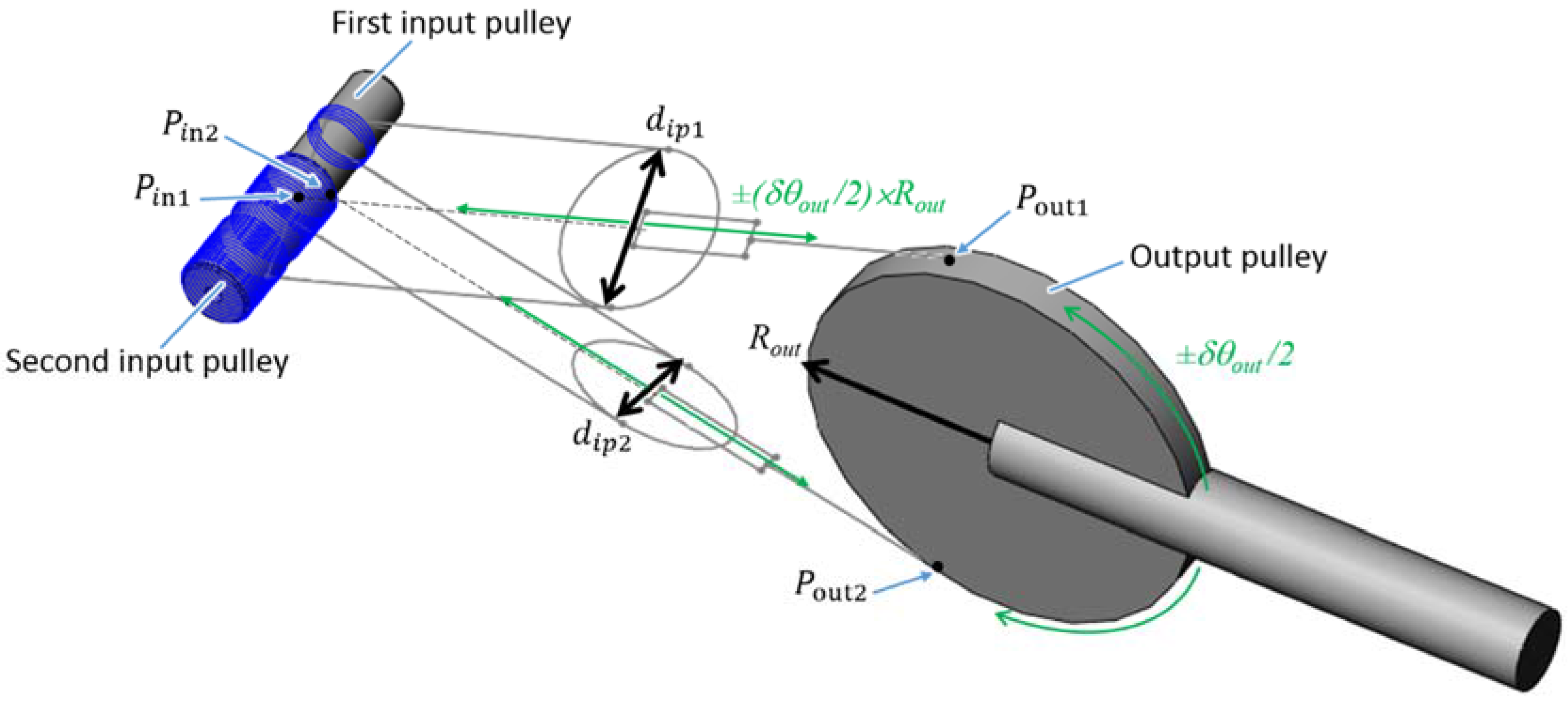
3.3.6. Global Dimensioning of the System
The radii of the different pulleys being known, the distance between the input and output pulleys can be fixed. Indeed, as shown on
Figure 4, when the output pulley turns of an angle
, the idler pulleys travel a distance equal to
. Hence, the distance between the input and output pulleys must be larger than
and
plus a small margin to avoid inter-pulley collisions. It is worth noting that, as can be seen from
Figure 3 and
Figure 4, some primary cables cross the paths of the idler pulleys when the latter moves toward the input pulleys. As a consequence, the distance between the pulleys must be increased to avoid collisions between the cables and idler pulleys. In practice, the occurrence of these collisions depends on the pulleys diameter and on the angle between the cables going in both directions and the distance between the input and output pulleys must be adjusted iteratively until no collision remains. This can be accomplished with a CAD software.
It is also worth noting that, as the input cables “advance” along the input pulleys when the system rotates, the distance between the point
(respectively,
) defined as the middle of the input and output points of the primary cable on the input pulleys and the point
(respectively,
) defined as the input of the secondary cable on the output pulley (this distance can be considered as some “virtual” length of the cables between the input and output pulleys) varies as a function of the output joint’s angle. As a consequence, the length of the free cable strands slightly changes when the system moves. In practice, however, the aforementioned constraints impose that the “virtual” length of the cables is very large compared to the cable advance along the pulleys’ axis and this elongation is negligible. As an example, the maximum elongation of the cables of the prototype presented below equals 0.14% of the cables’ length [
38].
3.3.7. Dimensioning Methodology
The equations presented above theoretically allow the successive dimensioning of the different components. In practice, the different choices are interdependent and the dimensioning of a differential cable drive is an iterative process.
Additionally, the theoretical values obtained as an output of the dimensioning process can be adapted due to other constraints as for example integration or cost constraints.
4. Development and Manufacturing of a Differential Cable Drive Actuator Prototype
4.1. Context of the Study
Given the potential advantages of differential cable drives, we decided to develop a 1-DOF prototype robot integrating such a reducer. In order to set the design drivers, we selected as a use-case a maxilla facial surgery simulator developed within the framework of the European Integrated Project SKILLS (IST-FP6 #035005, 2006–2011). This use-case has stringent requirements in terms of both transparency in free space and force quality rendering when force feedback is required, for which differential cable drives appear as a promising solution.
This simulator is a multimodal VR platform for the training of surgery skills [
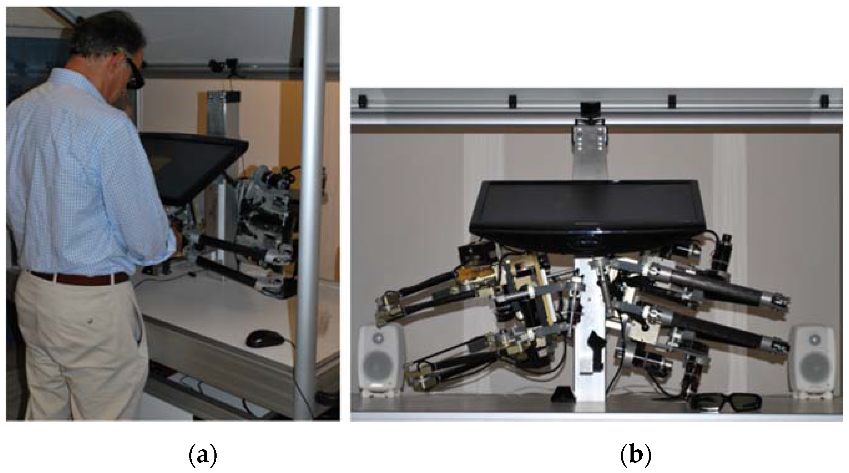
39], focusing more specifically on an operation called the Epker osteotomy which consists in moving the lower mandible forward or backward to correct an improper positioning of the teeth in the case of malformation or trauma. Therefore, the surgeon has in particular to drill the mandible bones. Experimental measurements made with a motion capture system and a force sensor during a data acquisition campaign performed in the anatomy laboratory of a university hospital with which we collaborated during these developments have shown that the most critical steps of this surgery require bi-manual movements in the Cartesian space with a maximum amplitude at the level of the surgery tool handle of about 162 to 194 mm in translation and 137° in orientation. The maximum measured efforts on the handle are in the order of 25 N and 1.5 N∙m (also in the Cartesian space). Finally, the bone stiffness is about 10,000 N/m. To allow for the simulation of this surgery, similar displacements and forces have to be reproduced at the level of the robot’s handle. Therefore, we developed two robots (one for each hand) having a hybrid serial and parallel architecture. As shown on
Figure 5, these robots are composed of two 3-DOFs sub-structures connected together at their tip and equipped with an additional pivot DOF in series. This structure combines the advantages of serial (large workspace in orientation) and parallel robots (good transparency in orientation). In practice, the left hand robot is a reconditioned version of a master arm previously designed for abdominal telesurgery, and the right hand robot is a new haptic interface with a higher force capacity and stiffness specifically developed for this platform. Further details on these robots can be found in [
23,
24].
4.2. Dimensioning and Design of the Differential Cable Drive Actuator Prototype
4.2.1. Design Drivers
With the idea to develop a prototype compatible with the SKILLS VR-platform, we used the specifications of the second axis of the SKILLS robot to set the prototype’s design drivers. The joint’s range of motion should be in the order of 131° and the prototype actuator should be able to develop a force of 15.5 N and display an apparent control stiffness of 5000 N/m at a distance of 340 mm from the joint axis. Thus, a joint torque of 5.27 N∙m is required.
4.2.2. Actuator Selection
After a careful study of the available actuators and an optimization of the motor-reducer association, a Maxon Motor RE25 118746 (24 V, 10 W, 0.0288 N∙m permanent torque) was selected, in association with a precise (i.e., 3600 ppt) rotor encoder.
To drive this actuator, we used a controller manufactured by Haption based on research results from CEA LIST [
40]. This controller implements a temperature model allowing the limiting of the input current and avoiding overheating and destroying the motor. In order to allow soliciting the actuator up to about 30 s, the input current is limited to three times the maximum continuous current. The peak torque is thus three times higher than the nominal torque. It is equal to 0.0864 N∙m.
This results in a required reduction ratio of 61:1 (please note that this value is obtained given the choice of actuator and controller, for a different choice another ratio would be required but the principles presented below would remain the same).
4.2.3. Cables Choice
A miniature steel cable of diameter = 0.95 mm is selected between the input pulleys and the reducer idler pulleys. This cable is highly flexible, yet of sufficient diameter to resist the motor torque. It can be wound on pulleys with minimum radius 8.1 mm. Even if a larger cable with a higher stiffness could have been used here, as the reduction ratio no more depends on the input pulley’s diameter as with conventional capstan cable drives, this would increase the bulkiness of the reducer as will we demonstrate hereafter. A second miniature steel cable with a larger diameter ( = 1.80 mm) is used between the reducer idler pulleys and the output pulley.
4.2.4. Dimensioning of the Output Pulley
With a secondary cable of diameter
= 1.80 mm, the output pulley’s radius should be larger than
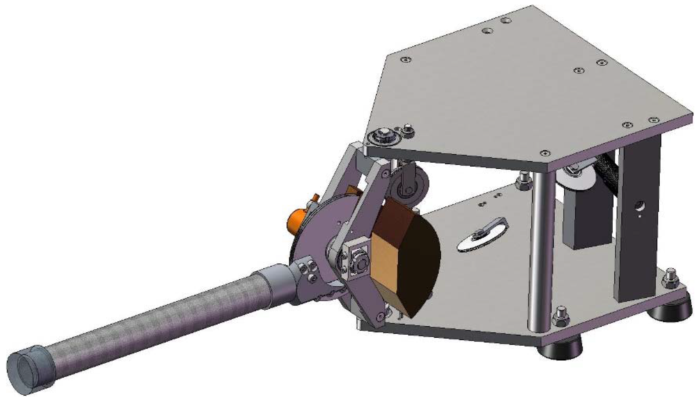
15.3 mm. In practice, however, as shown on
Figure 6, the differential cable drive studied in this section differs from the system shown on
Figure 2 and
Figure 4 from two respects.
Firstly, the device is statically balanced with a counterweight. Such a counterbalancing system, being either passive or active, is necessary on haptic interfaces in order to limit the fatigue of the user and avoid the system to fall in case the user drops the handle. To be efficient, such a counterweight should be either sufficiently heavy or placed at a sufficient distance from the joint’s axis. The maximum reasonable weight fixed the distance which in turn constrained the pulley’s diameter (we chose to directly fix the counterweight on the output pulley). This results in an output pulley of radius = 50 mm (at the level of the neutral cable fiber).
Secondly, the secondary cable is not directly attached to the output pulley. As shown on
Figure 6 and
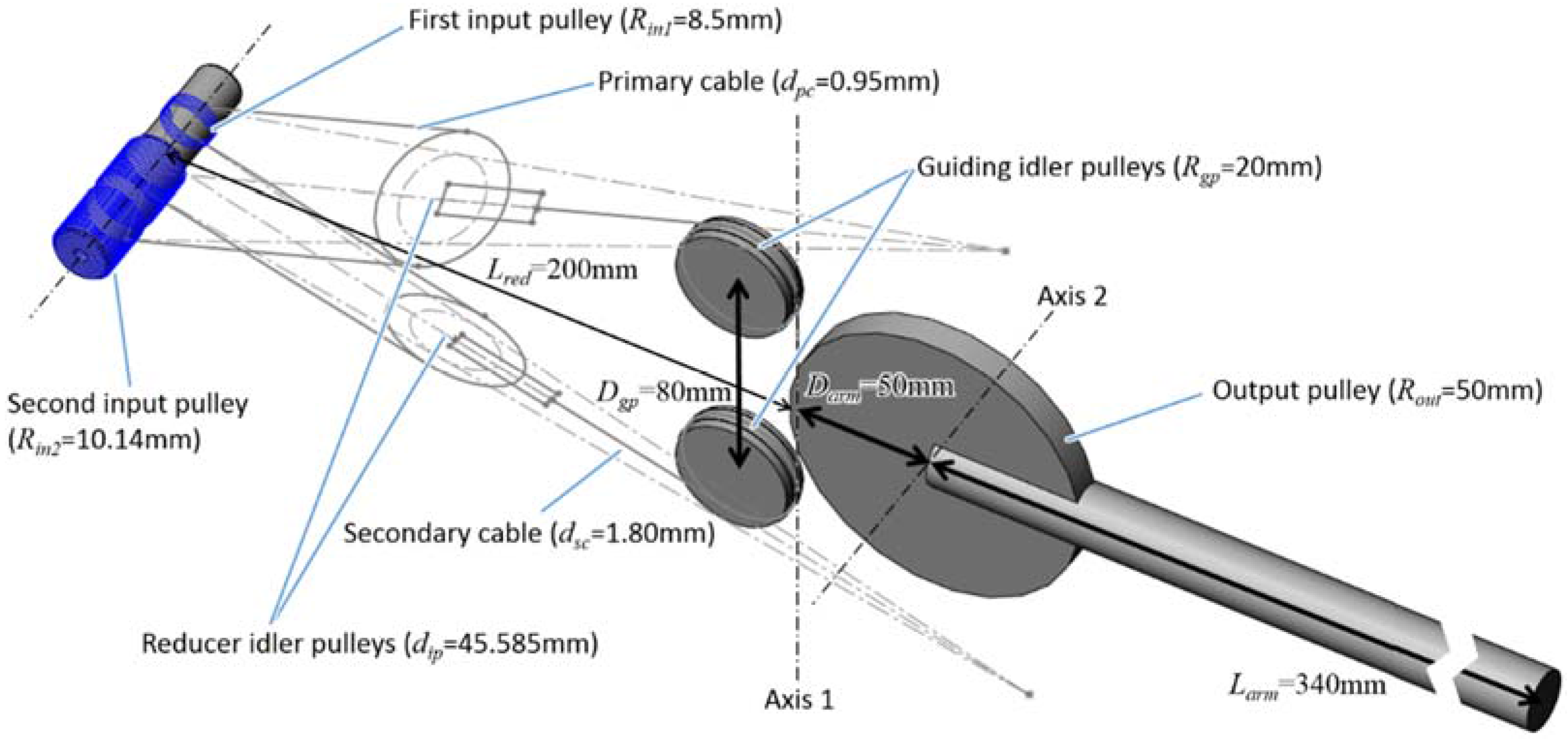
Figure 7, it goes first around guiding pulleys. This is due to the fact that, even if the developed prototype has only one actuated DOF, it is representative of the second axis of the robots illustrated in
Figure 5 (called Axis 2 in
Figure 7). As a consequence, the proposed design also integrates a passive moving axis (called Axis 1 in
Figure 7) representative of the first axis if these robots. Hence, two additional guiding idler pulleys (with radius
= 20 mm here and distant from
= 80 mm) are used to modify the output cable trajectory and guide it along the first axis of rotation of the robot. This way, movements around axis 1 and axis 2 are decoupled,
i.e., the robot can rotate around axis 1 without any modification of the angle around axis 2 (this modification has no influence on the principle of operation of the reducer). Additionally, as shown in
Figure 6, the actuator and reducer are placed on the side of the sagittal plane of the prototype. It is, thus, possible to integrate a second actuator in order to actuate the third axis of the robot.
4.2.5. Dimensioning of the Input Pulleys
In order to obtain a reduction ratio of 61:1, we made use of input pulleys with radii
= 8.5 mm and
= 10.14 mm (at the level of the neutral cable fiber). These dimensions, both larger than
8.1 mm, are illustrated in
Figure 7 and serve in the CAD design shown in
Figure 6.
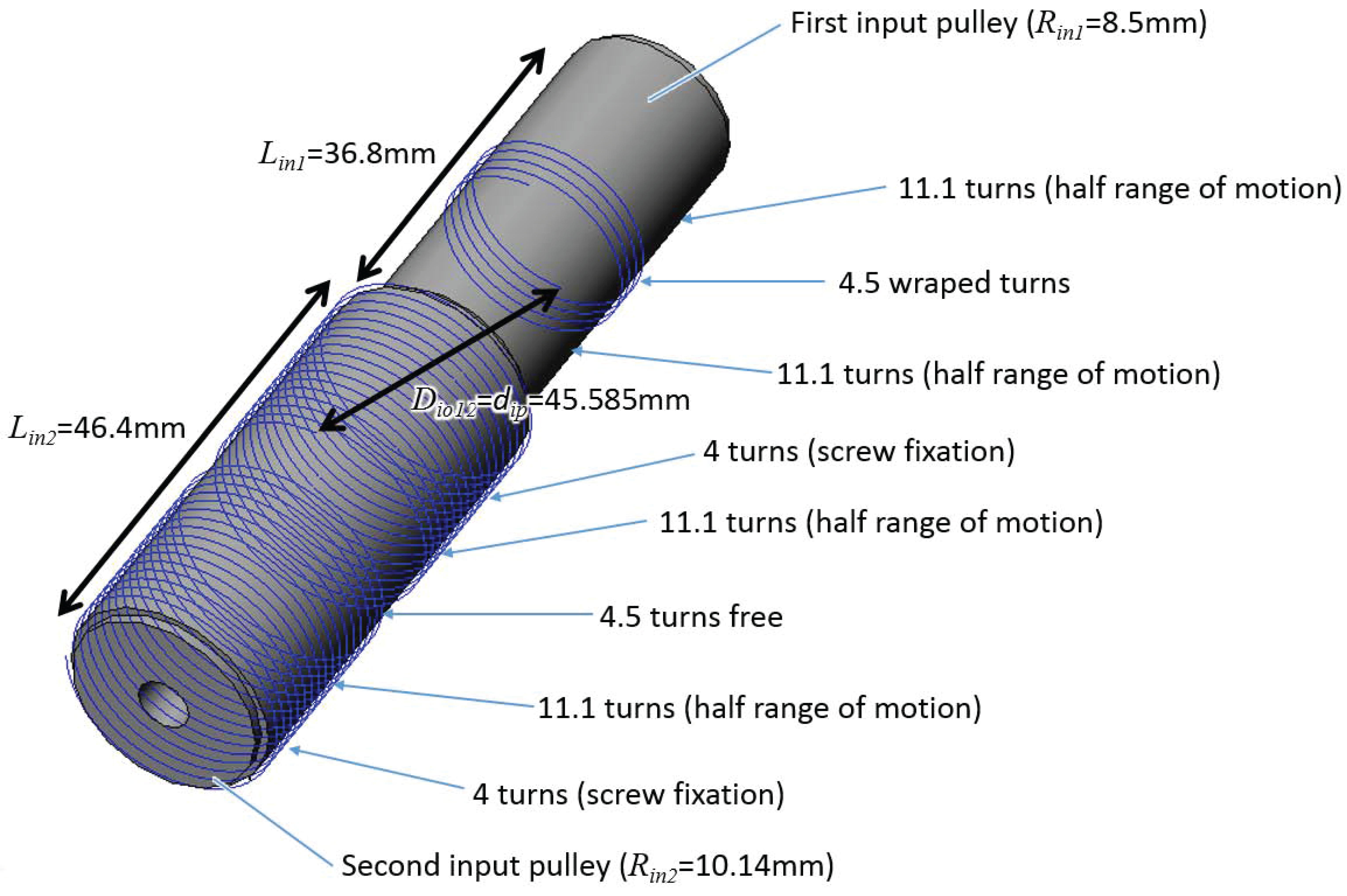
Figure 8 shows additional details on the dimensions of the input pulleys. A first end of the input cable is attached at the first end of the second input pulley using a screw. It is then wound around the pulley, with a sufficient number of turns to allow for half the joint’s range of motion in one sense. Then the cable exits the pulley, is wound around a first reducer idler pulley and enters the first input pulley. It is then wound around the pulley, with a sufficient number of turns to avoid slipping (here 4.5 turns are sufficient). Then it exits the first input pulley, is wound around the second reducer idler pulley, and enters the second input pulley around which it is wound with a sufficient number of turns to allow for half the joint’s range of motion in the other sense. Finally, the second end of the cable is attached to the second input pulley using a screw. It is worth noting that 11.1 turns of cable must be left free on both sides of the cable wound around the first input pulley to allow for the cable to move along this pulley when the joint moves half its range of motion in both senses (the range of motion is 131° here, slightly larger than in the example given in
Section 3.3). Additonally, the same number of turns as on the first pulley,
i.e., 4.5 turns, are left free between the input and output strands on the second input pulley. Finally, the screws heads blocking the cable occupy about four turns at each end of the cable. The thread pitch being here 1.2 mm for the cable of diameter
= 0.95 mm (about 1.25 times the cable diameter), the total length of the first input pulley equals
= 36.8 mm, taking into account a small margin on both sides of the pulley. The length of the second input pulley equals
= 46.4 mm.
4.2.6. Dimensioning of the Idler Pulleys
Considering the dimensions of the input pulleys, the distance between the cable strands exiting the second input pulley and entering the first one equals = 45.585 mm. This value is taken as a reference for the idler pulleys diameter ( = 45.585 mm, see Equations (12) and (13)).
4.2.7. Global Dimensioning of the Reducer Prototype
For a joint’s range of motion = 131° and an output pulley’s radius = 50 mm, the translation of the idler pulleys reaches 57 mm in both directions and the input pulleys must be placed = 200 mm behind axis 1. Having a larger input cable would increase both the input pulleys diameter and the thread pitch and, hence, longer and larger pulleys. Larger idler pulleys would also be required, which would span a larger space, hence, in turn a longer distance between the pulleys’ axis and axis 1. Globally, the reducer would be much more bulky.
4.3. Prototype Manufacturing and Integration
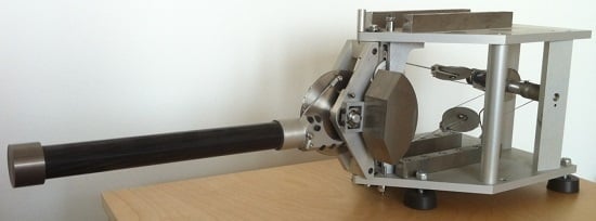
A 1-DOF robot prototype integrating a differential cable reducer was manufactured, assembled, and tested. It is worth noting that both the cables and actuator were changed compared to the theoretical dimensioning presented above. The primary and secondary cable were replaced with cables of diameter = 0.9 mm and = 1.75 mm available in the laboratory. The actuator with precious metal brushes initially selected was replaced with a version with graphite brushes that was also available in the laboratory (Maxon Motor, ref. RE25 118755, 48 V, 20 W, 0.0244 N∙m permanent torque). This actuator exhibits substantially higher friction than the actuator initially selected (0.88 mN.m instead of 0.63 mN∙m). Furthermore, this actuator was equipped with a 1000 ppt MR encoder (Maxon Motor, ref. 225780, 1000 ppt, three channels) instead of the 3600 ppt encoder selected for the dimensioning of the system. It allows a much less precise measure of the rotor position and, hence, a relatively low control stiffness (here only 0.24 N∙m/rad) compared to the stiffness usually observed on similar actuators (about 1 to 1.5N∙m/rad). In order to increase this value, an inertial disk was fixed on the input pulleys to increase the rotor inertia and stabilize it. With this disk, a control stiffness of 0.49 N∙m/rad was obtained. The apparent inertia seen by the user is only marginally increased as most of the inertia comes from the link and counterweights. Finally, a 3600 ppt encoder is used as a reference at the joint level (TWK, ref. GIO-24H-3600-XN-4R).
A first test campaign was performed with this prototype, allowing the validation of the principle of operation of the reducer. However, the basis of the robot, as well as the support of the guiding idler pulleys, exhibited some compliance. As a consequence, the latter were not properly maintained along axis 1 and introduced additional compliance and friction.
To overcome these limitations, reinforced basis and pulley supports (compared to the CAD design in
Figure 6) were introduced and a second test campaign was performed with this improved prototype. Except when it is explicitly stated, the results given in
Section 5 were obtained using this reinforced prototype.
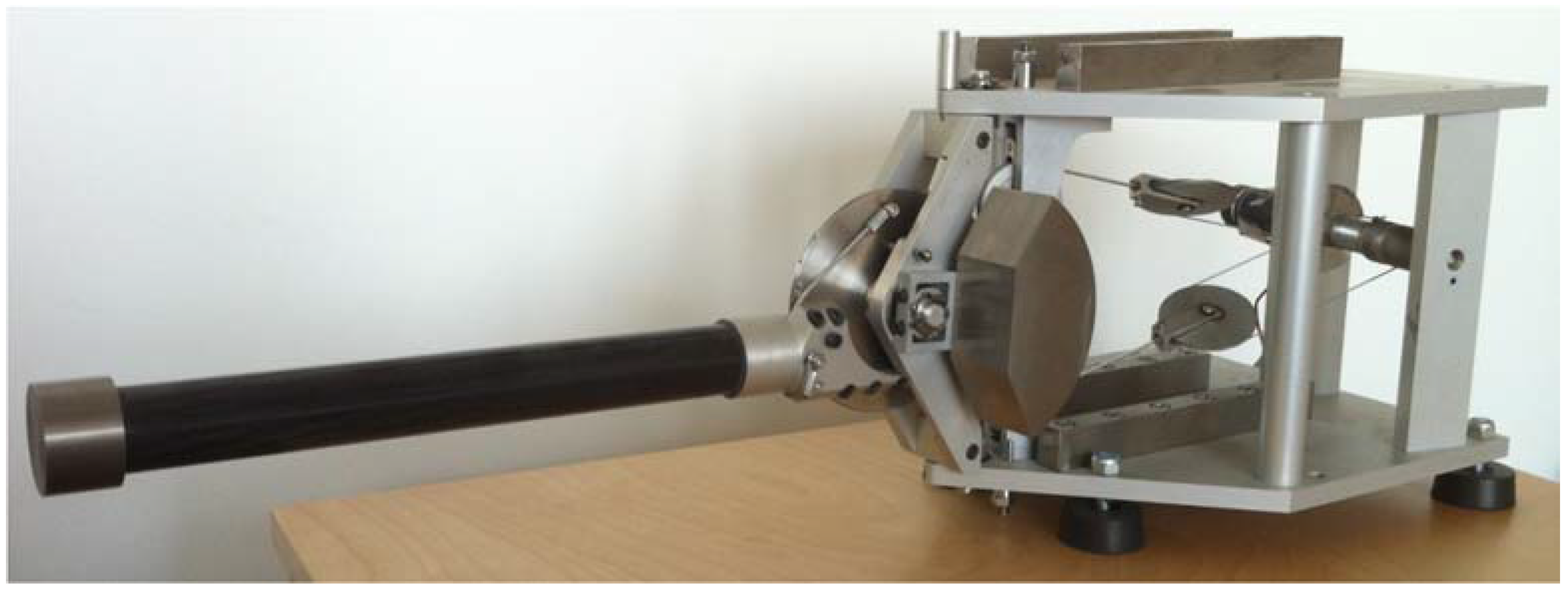
The improved prototype is shown in
Figure 9. Its theoretical performances are given in
Table 1. In this table, only the motor friction is taken into account, not the bearing friction. For the stiffness, we consider both the motor control stiffness (
i.e., the maximum stable position static gains in the controller) and the cables stiffness computed in the reference position illustrated in
Figure 7. The robot is statically balanced around axis 2 using tungsten counterweights visible in
Figure 9.
5. Performances Characterization
5.1. System Preload
Slack strands must be avoided in belt and cable drive systems. Therefore, the cables must be preloaded with half the maximum applied force. Pre-tensioning bolts are, therefore, available in the prototype. By moving the upper and/or lower guiding idler pulley up or down, the tension in the cables can be adjusted to the desired value.
In practice, a given force
is applied downwards by the operator at the tip of the arm and the upper bolt is screwed until the input and output cables as well as the reducer idler pulley lie in a plane. Given the arm dimension equal to
= 340 mm and the output pulley radius
= 50 mm, the cable pretension
is given as a function of the maximum force in the cable
and the maximum applied force
using the following function:
Here, the theoretical maximum force equals only 13.13 N, hence a pre-tension of 44.64 N. However, in order to better observe the influence of cable preload on the system performances, pretensions up to much higher values are considered, i.e., 34, 68, 102, and 136 N, corresponding to maximum applied forces of 10, 20, 30, and 40 N. As the actuator is not able to resist such high forces, the input pulleys are blocked mechanically during the preload phase.
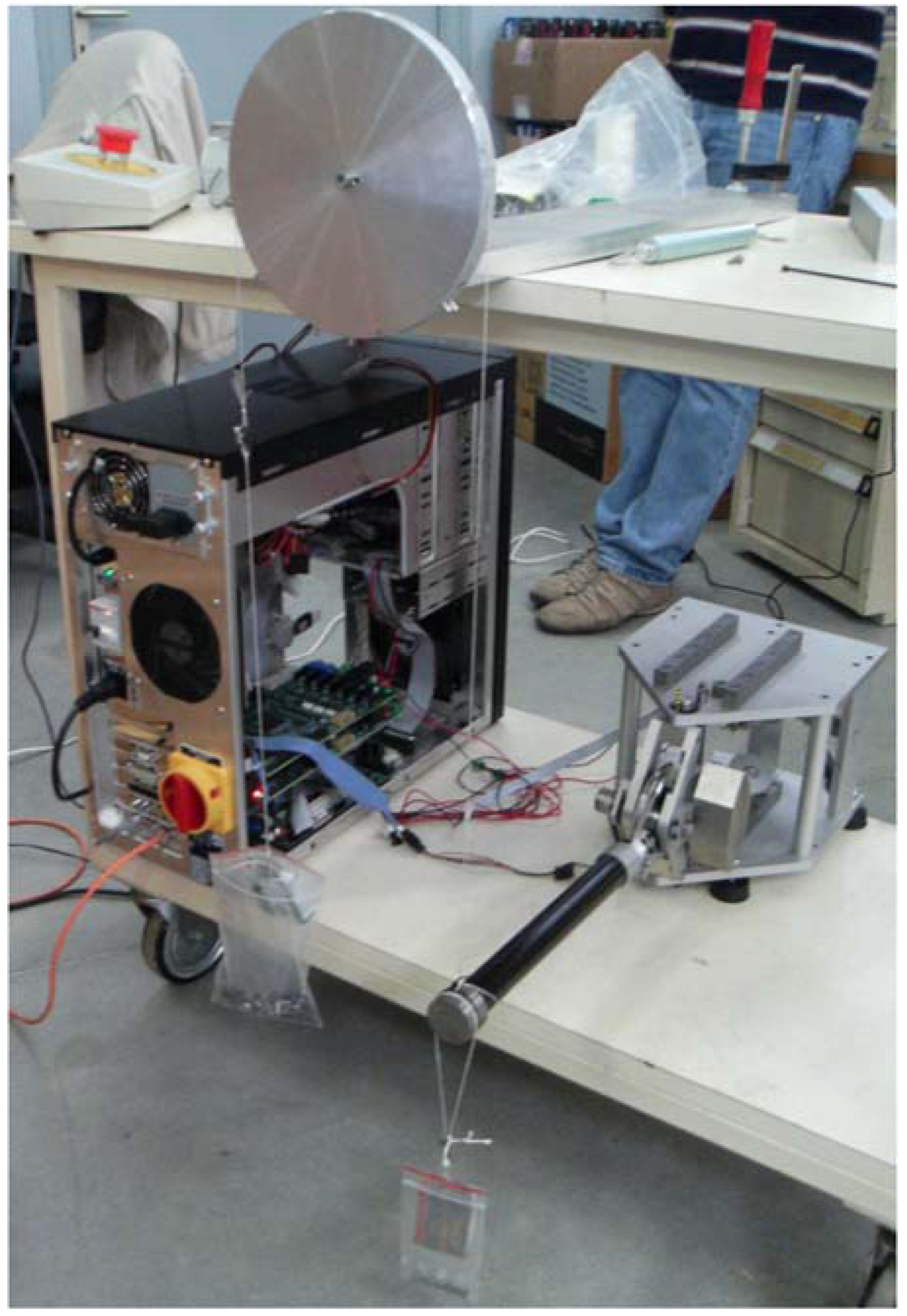
5.2. Characterization of the Actuator Friction
Figure 10 illustrates the configuration used to measure the actuator’s static friction (
i.e., the force that a user has to overcome before he can move the device). Axis 1 is blocked at the center of its range of motion and the arm is placed horizontally. The controller is turned on and the desired forces set to 0 (all gains equal to 0).
Two masses
and
are attached to the arm tip with strings (in practice at a distance
= 330 mm from axis 2). The first string directly induces a downwards movement of the arm. The second string is routed around a large equilibrated pulley whose friction
has been previously identified. It is equal to 0.08 N for an unloaded string and 0.1 N when the string is loaded with a mass of 105 g, the pulley’s friction being supposed to vary linearly with the string load. During the measurements,
, respectively
, is increased (with
, respectively
, being kept constant) until the arm moves upwards or downwards. The equivalent moving forces are computed using the following formula:
with
.
with
.
By denoting
the global friction force and
the force generated by static balancing defaults, both computed at the arm tip, we have
and
, hence:
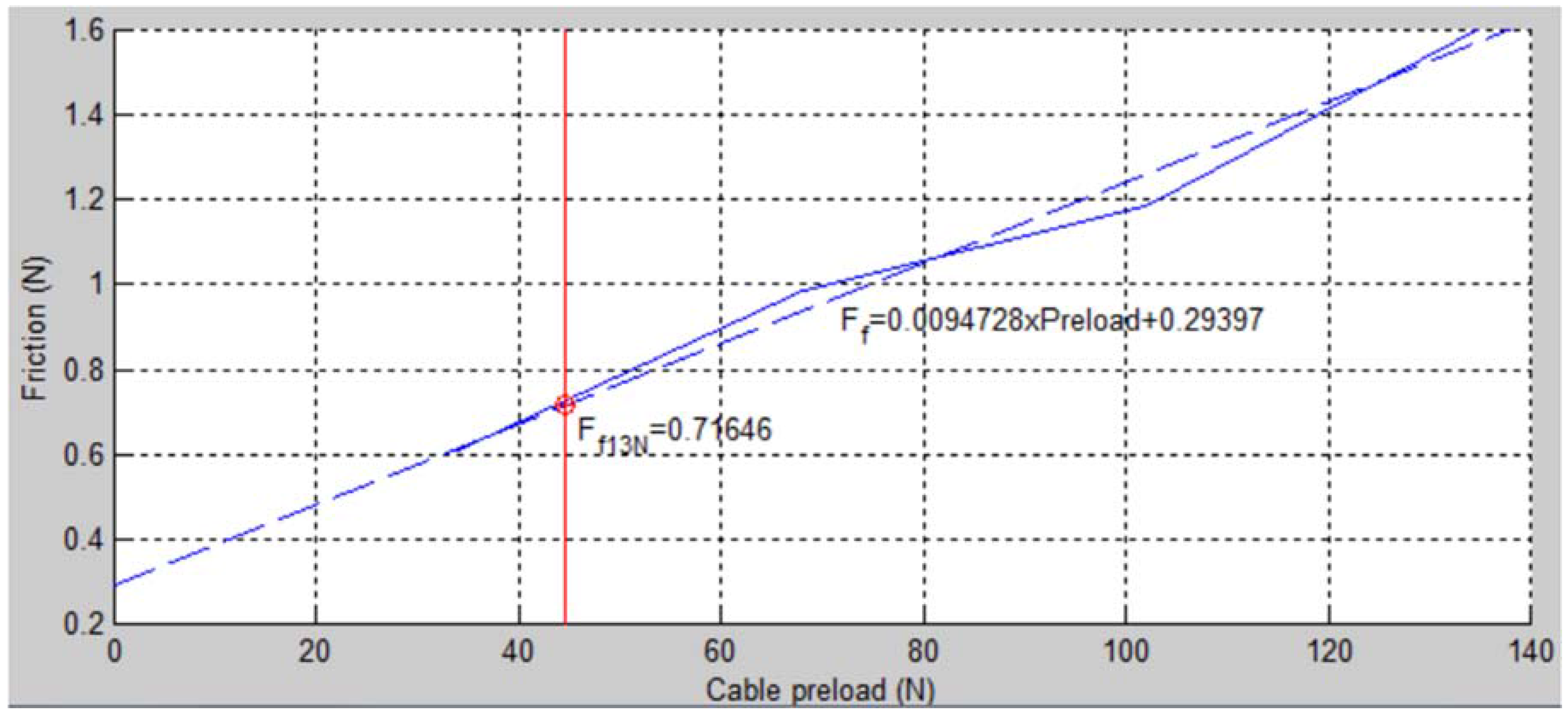
The results are illustrated in
Figure 11 (the friction is measured along the local direction of movement,
i.e., along the vertical axis in a Cartesian space). For a pretension of 44.6 N corresponding to the nominal conditions (
= 13.13 N), the friction in the cable is equal to 0.71 N, that is about 5.4% of the maximum force.
5.3. Characterization of the Actuator and Cable Stiffness
To further characterize the behavior of the device, we choose to focus on stiffness rather than on bandwidth. Indeed, in practice, with existing haptic interfaces, the static deviation of the handle under a given applied force is a more limiting factor than the dynamic response of the robot. As a matter of fact, the devices from the state of the art are usually relatively compliant (see
Section 5.4 for examples) but they still have a high bandwidth thanks to a very low inertia. As a consequence, the users of these devices usually have a good feeling when coming in contact with virtual surfaces. However, once in contact, it can be observed that the position of the device’s handle can be relatively away from the theoretical position of the virtual wall due to this limited stiffness. While this is not a problem when one only wants to inform the user that a virtual surface was encountered, this becomes a real limit when trying to learn sensori-motor skills as with the SKILLS VR platform for which our device is developed. If the device is not at the right place when applying the right force, the user will learn wrong force-position schemes, and this will be dangerous when he moves to a real operating room.
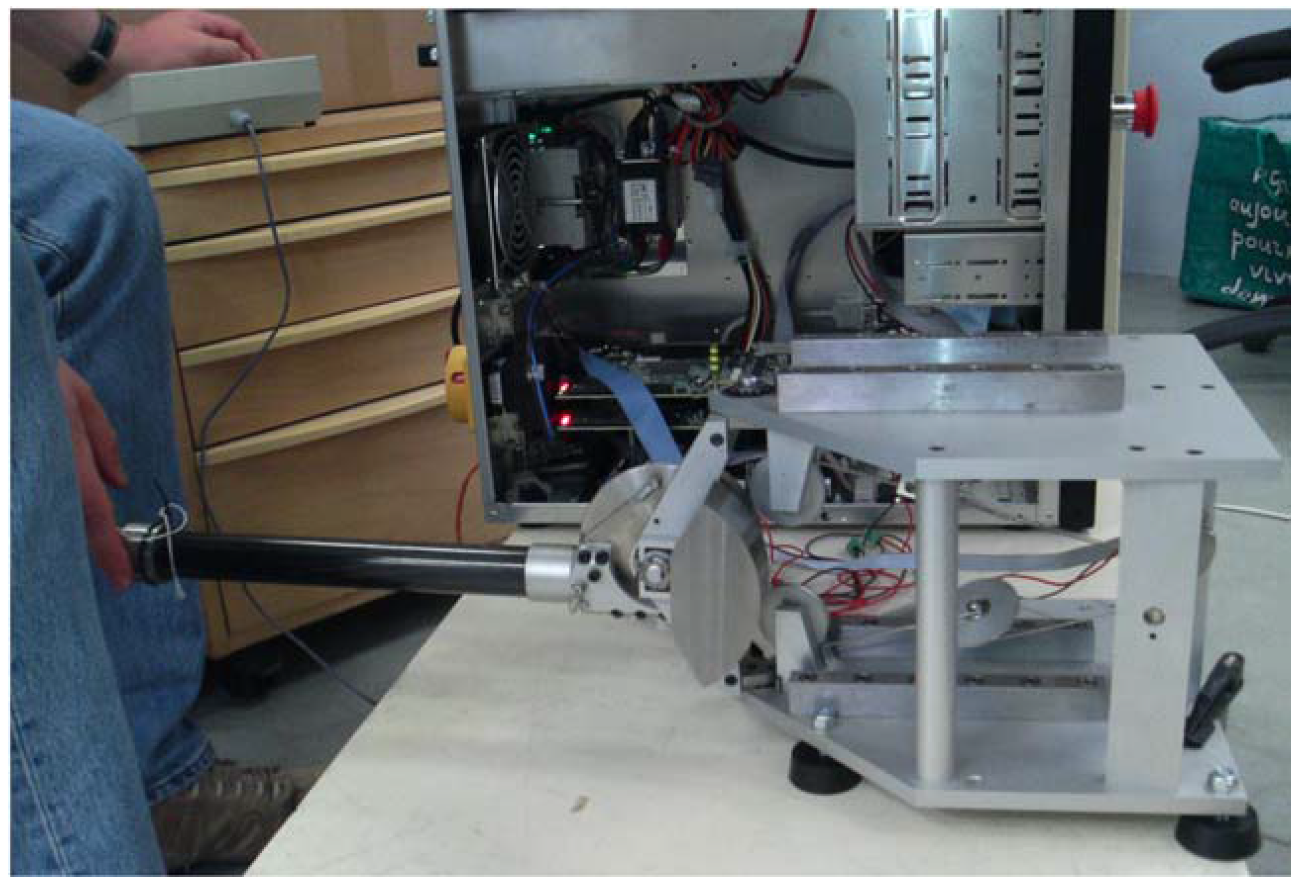
To characterize the response of our prototype, the actuator maximum stable static gain is adjusted for each value of the cable preload. Therefore, a fixed reference position is set and the operator tries to destabilize the system, either by hitting the arm manually or by pushing the arm’s tip and releasing it suddenly. The gains are increased until a detectable vibration occurs.
Once the maximum gains are obtained, the arm is still controlled so as to remain in a fixed position and both the actuator’s position and current are recorded while the user moves its tip (see
Figure 12).
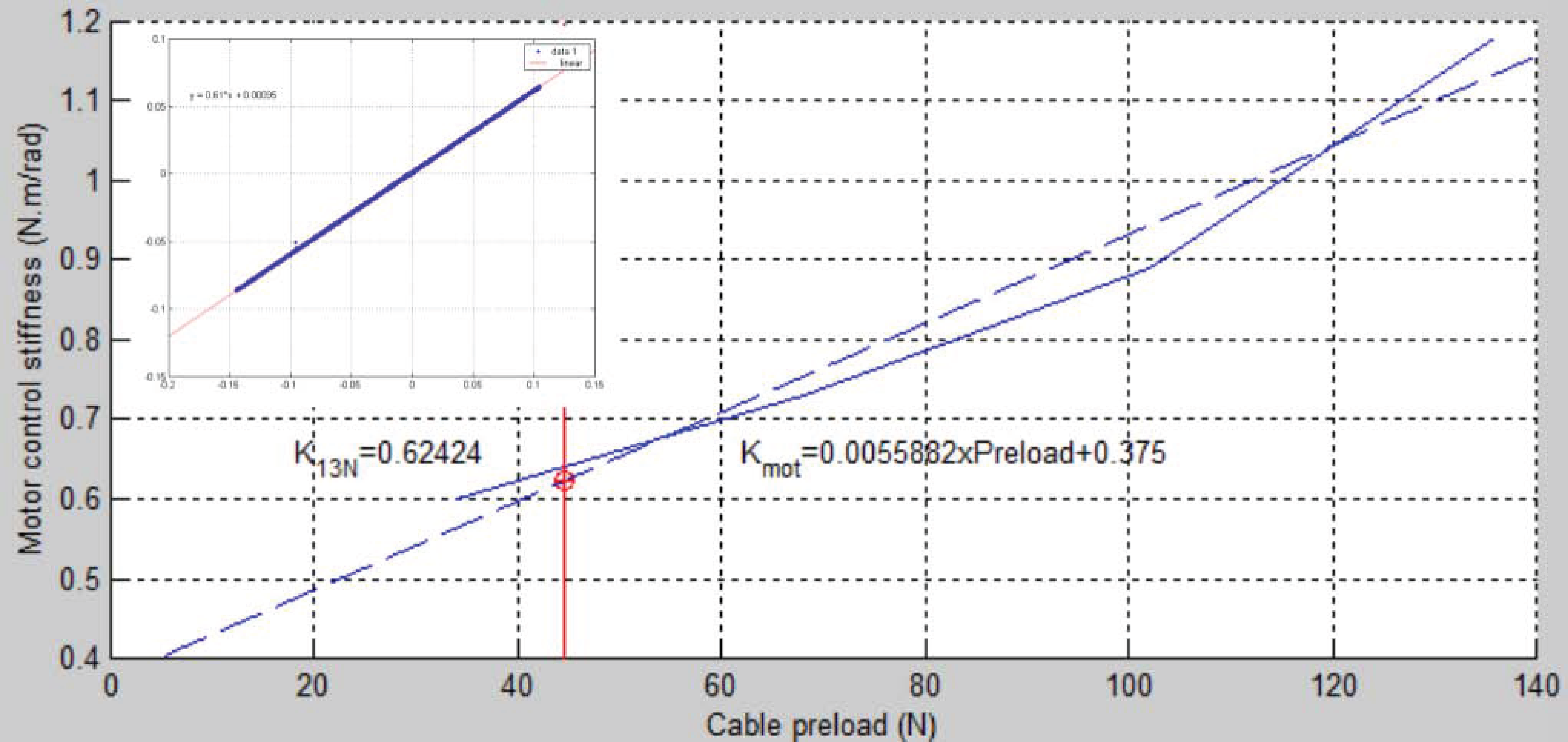
The results obtained for the different values of the cable pre-load are illustrated in
Figure 13. The small stamp in the top left corner illustrates the relationship between the motor position and torque for a preload of 34 N. It can be seen that the motor torque varies linearly with the rotor deflection, with an almost null hysteresis. The maximum motor control stiffness increases with preload as preload has a stabilizing effect. Under the assumption that the relationship between preload and maximum control stiffness is linear, the motor control stiffness is equal to 0.38 N∙m/rad for a null preload. This is relatively close to the theoretical value of 0.49 N∙m/rad given in
Table 1. Furthermore, for a preload of 44.6 N corresponding to the nominal conditions (
= 13.13 N), the motor control stiffness equals 0.62 N∙m/rad, which is higher than this theoretical value.
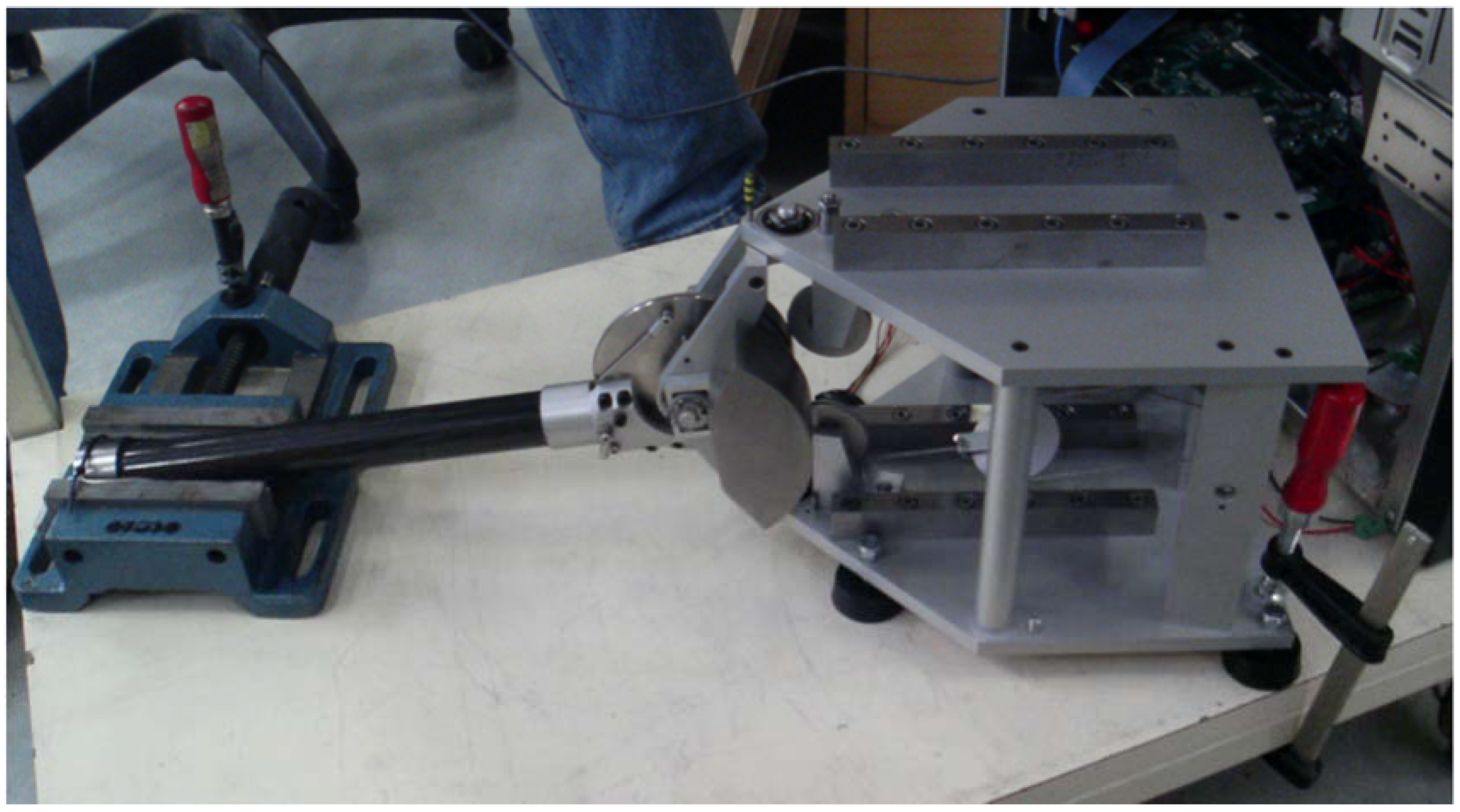
The prototype was also used to measure the mechanical stiffness. Therefore, we made use of a similar procedure as described in [
41,
42]. As shown on
Figure 14, the arm was blocked and sinusoidal movement orders were sent to the motor. The parameters are identified with a linear least-squares approach. The measures of the motor and joint’s encoders and the motor input current are used as inputs to compute the motor inertia
, the transmission stiffness
and damping
, the friction in the transmission
, and the measure offset, all data being measured in the motor space.
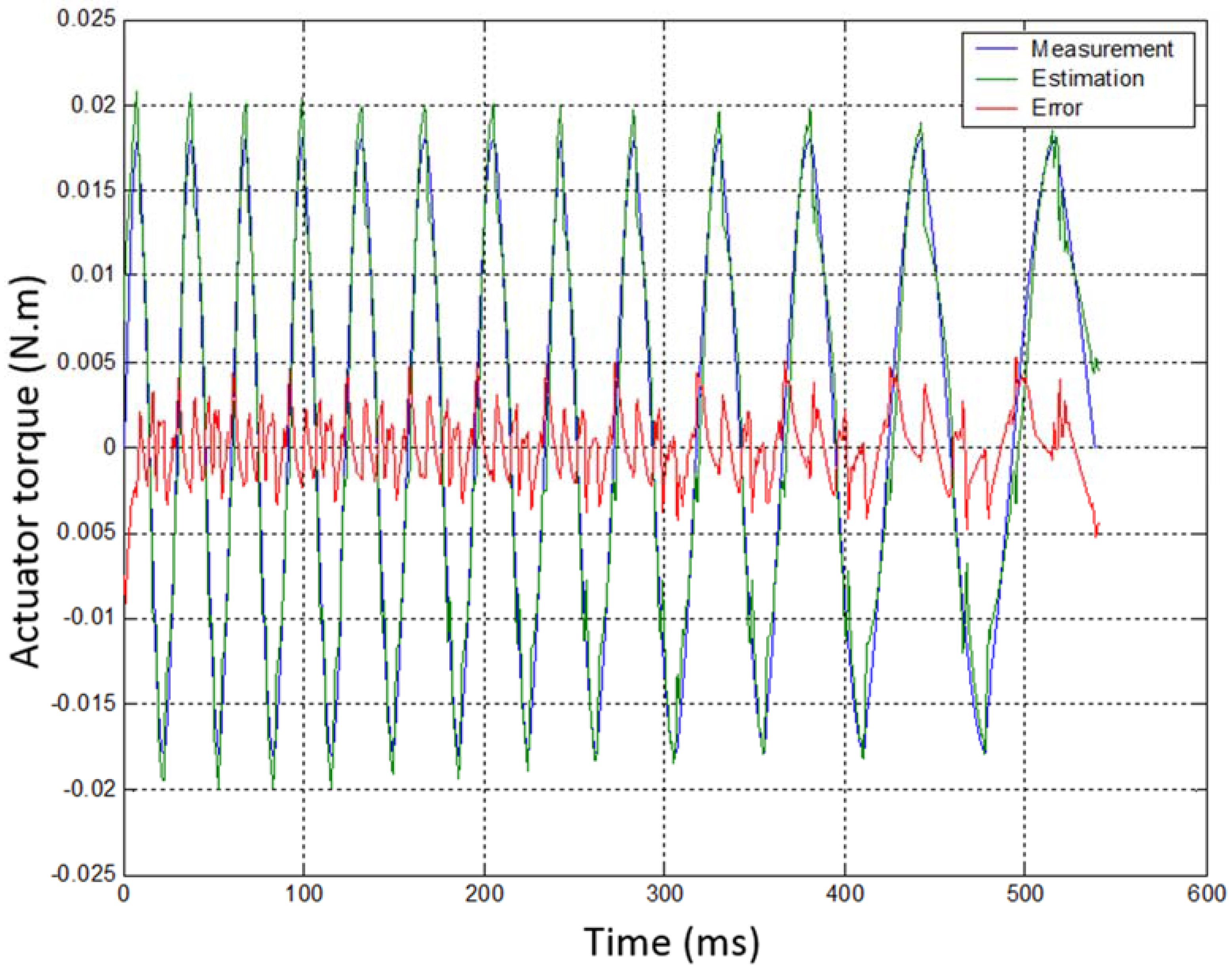
Table 2 gives details on the identified parameters of the transmission and
Figure 15 illustrates the measured and reconstructed results. These measures are performed with a high cable preload of 136 N. Measures made with lower cable preload were not exploitable due to a shifting hysteresis (
i.e., drift of the measures over time) probably due to small prototype movements. The dominant parameter (
i.e., the parameter having the highest influence on the system dynamics and thus identified with the best reliability) is the transmission stiffness. On the contrary, the rotor inertia is very small and has a very limited influence. As a consequence, it can barely be identified. This is, however, not a problem as, contrary to stiffness, which was the focus of this test campaign, its value can be estimated from motor specifications and CAD data.
As the transmission stiffness for lower values of the cable pre-tension is not available with the reinforced prototype, we used data obtained with the initial non-reinforced prototype in order to have an idea of the influence of the cable pre-tension on transmission stiffness. Indeed, as highlighted in
Section 4.3, two identification campaigns were performed. While the second one, from which all the results in
Section 5, except here, are the results, did not allow identifying the transmission stiffness for lower cable tensions, this data is available for the first (non-reinforced) prototype. It is worth noting, however, that the transmission stiffness of this first prototype was lower than that of the reinforced one due especially to more compliant supports of the guiding pulleys (see CAD design of the first prototype in
Figure 6 and reinforced prototype in
Figure 9). To fit both data, we shifted the results obtained with the first prototype so that the data correspond to those of the reinforced one for a preload of 136 N, with the hypothesis that the effect of cable preload is then the same for both prototypes (
i.e., the slope of the fitted line is the same).
The results are given in
Figure 16. It can be seen from this picture that the cable stiffness for a preload of 44.6 N corresponding to the nominal conditions (
= 13.13 N) is only equal to 0.18 N∙m/rad. This corresponds to an apparent stiffness of 5750 N/m at the tip of the arm. This value is about the half of the theoretical value given in
Table 1. All cables probably do not work in parallel as hypothetized. Still, this stiffness is relatively high compared to existing haptic interfaces.
5.4. Discussion
Table 3 summarizes the theoretical and experimental performances of the 1-DOF robot prototype integrating a differential cable drive reducer. It can be seen that the friction in the system is higher than the theoretical value. The latter was, however, computed taking into account only the actuator. It is no surprise that the pulleys and bearings also generate some friction. Still, the friction is only 5.4% of the force capacity of the prototype, which is quite low compared to alternative solutions that can be used to design a 61:1 reducer (e.g., gear trains, harmonic drive,
etc., which have the advantage of being more compact and lighter than cable drive systems). These results also demonstrate that the actuator stiffness, while being lower than anticipated due to a lower transmission stiffness, remain quite high compared to usual haptic interfaces and collaborative robots.
As a whole, these results prove that the proposed concept of a differential cable drive reducer exhibits a low friction and a high stiffness, which are the most important features of haptic interfaces (the former having in practice the highest influence on the perception of transparency in free space, the later fixing limits on the environments which can be perceived as realistic in contact). It is quite difficult to compare these results with the performances of other existing devices as their specifications in terms of force and workspace, which have a direct influence on friction and apparent stiffness, are different. Still, we can see that our prototype lies between the Sensable PHANToM Premium 1.5 and 1.5 High Force from Geomagic, which are references in the field of haptics. Indeed, they have a comparable workspace (195 mm × 270 mm × 375 mm) and the mean of their maximum force capacity (1.4 N and 8.3 N, with a mean of 4.85 N) is close to the maximum continuous force or our device (we chose here to compare the continuous force capacity of both devices, the peak force capacity being much more difficult to compare as they are not computed the same way, the Haption controller limiting the maximum current in order to avoid instantaneous overheating of the motors while Sensable’s specification sheets give peak forces that cannot be maintained more than a few second at best). The backdrive friction of our prototype (0.71 N) is higher than with the Sensable devices (0.04 N and 0.2 N, hence a mean of 0.12 N) and should be reduced. Yet, its control stiffness is much higher (more than 15,000 N/m compared to 3500 N/m). Our prototype also favorably compares with the Virtuose 3D Desktop and Virtuose 6D Desktop from Haption which have a similar workspace (200 mm × 200 mm × 200 mm) and force capacity (3 N continuous, 10 N peak) and which despite a more recent controller exhibit a maximum control stiffness of only 2000 N/m. Only the omega.3 haptic interface from Force Dimension has a similar control stiffness (14,500 N/m), with a same amount of force (12 N maximum), at the price, however, of a smaller workspace (only 160 mm × 160 mm × 110 mm when the SKILLS robot with which our reducer is compatible reaches 380 mm × 380 mm × 390 mm [
24]).
The differential cable drive reducer is backdrivable and overcomes the limitations of conventional cable capstan reducers, i.e., a limited reduction ratio. It is well suited for applications in interactive robotics which require a relatively high force capacity.
6. Conclusions
In this paper, we introduced a new differential cable drive reducer. This reducer relies on the same principle as cable capstan drives. The input pulley is, however, replaced with two coupled input pulleys of different diameters. It is demonstrated that this modification allows the reduction ratio to be no more defined as the ratio between the output and input pulleys’ radii, but as the ratio between the output pulley radius and the difference in the input pulley’s radii. This way, a very high and potentially infinite reduction ratio can be easily obtained. Additionally, it is highly backdrivable, exhibits a relatively low friction, and has a high efficiency.
A 1-DOF prototype robot integrating such a reducer was designed, manufactured, and integrated on a test-bench used to identify its friction, control, and transmission stiffness. The obtained results prove that the differential cable drive actuator is backdriveable, exhibits a low friction and a high stiffness. It confirms its theoretical advantages.
The proposed differential cable drive actuator is well suited for applications in interactive robotics which require a relatively high force capacity.


