1. Introduction
Dielectric Electric Active Polymers (DEAP) actuators are a new type of actuators characterised by large strokes, low weight and low cost. They have been used in different applications among which robotics, haptics, energy harvesting, vibration control, sensing and acoustics. Their working principle is based on compliant electrodes [
1,
2]: in their classical configuration, an elastomer is sandwiched between two compliant electrodes. When voltage is supplied to the electrodes, an electromechanical pressure squeezes the composite structure [
3]. Because of the electromechanical pressure, both axial and transversal deformations are experienced. To obtain a useful stroke and force range for actuation purposes, several configurations are used, which may involve mechanical bias (e.g., an external pressure, deformable frames or internal springs) [
4,
5,
6,
7] or stacking and folding approaches [
8,
9,
10,
11].
A novel design for such actuators has been recently proposed which utilises rigid-perforated metal electrodes [
12,
13]. This design shows a more homogeneous strain distribution, highly conductive electrodes and a high breakdown voltage across a large range of deformations. It proves to be especially advantageous for applications where only moderate strains are needed, but good dynamics and load-bearing capabilities are required. In contrast to conventional designs, such actuators only contract in one direction, whereas all other directions remain un-deformed. In this way, it is possible to build actuators made of few layers only, which are of particular interest to realise extremely flat loudspeakers.
Dielectric elastomer loudspeakers with compliant electrodes have been proposed in different configurations [
1,
14]. In a similar way to electrostatic loudspeakers, a thin dielectric film radiates sound in response to an oscillating voltage. Their operation voltage is of the order of 1 kV and characterised by a bias and a modulation component. While the bias voltage applies an electromechanical pre-straining which is beneficial to the overall performances, the modulation component of the voltage is responsible for the sound generation. Compared to traditional loudspeakers they have a smaller mechanical impedance and are able to achieve larger displacements. Hence, a high sound pressure field can be generated with loudspeakers of moderate size. Because of their deformation mechanisms, they are in some ways analogous to monopole sources and they can potentially show better directivity performance than traditional loudspeakers. However, since the displacement is driven by Maxwell pressure law [
3], they are inherently nonlinear. Heydt et al. [
1,
14] proposed a method to reduce nonlinearity by the implementation of a push–pull configuration. By using two loudspeakers with different mechanical bias which are driven with out-of-phase modulating voltage, it is possible to have destructive interaction of the higher order frequencies.
Mechanical bias is generally applied by pressurising a chamber at the back of the moving film. It is then possible to realise loudspeakers which are almost hemispherical. Hosoya et al. [
15] investigated a small lightweight dielectric elastomer loudspeaker in a hemispherical shape vibrating in the breathing mode to realise a point sound source. They showed that the designed loudspeaker behaves as a practical omnidirectional source in a frequency range up to 16 kHz. Since it is difficult to keep this chamber pressurised, Graf and Maas [
16] proposed a method to apply the mechanical bias using a polymer membrane. In such a way, the problem of keeping the chamber pressurised is solved and very thin loudspeakers can be manufactured. However, the force applied is not well distributed and this affects the sound reproduction quality and directivity.
The rigid perforated electrode technology has been used previously only for linear actuators. In this paper, a flat DEAP loudspeaker with perforated rigid electrodes is proposed and tested for the first time. Hence, this paper presents novel advancements from both rigid perforated electrodes actuators and compliant electrode loudspeakers. In relation to compliant electrode loudspeakers, such design does not need mechanical bias and the increased conductivity of the rigid electrodes allows for the use of less demanding amplifiers and to cover the full audible frequency range. The proposed loudspeakers are lighter, cheaper and thinner than conventional loudspeakers. In fact, differently from conventional coil loudspeakers, no resonating sound box is needed and an extremely flat configuration can be obtained. The same argument can be made for electrostatic and distribute mode loudspeakers [
17]. Distributed-mode loudspeakers present diffuse film but also some sonic coloration and a thickness of about 10 cm. Electrostatic loudspeakers present exceptional and linear sound quality but, due to their rear radiation, must be placed away from walls. On the other side, differently from conventional electrostatic and dielectric elastomer loudspeakers with compliant electrodes, it is possible to stack multiple layers to have larger displacement with lower applied voltage. In addition, since they do not need a mechanical bias, the sound emitting film can be manufactured in any desired shape.
2. Working Principle and Theory of Dielectric Elastomers with Perforated Electrodes
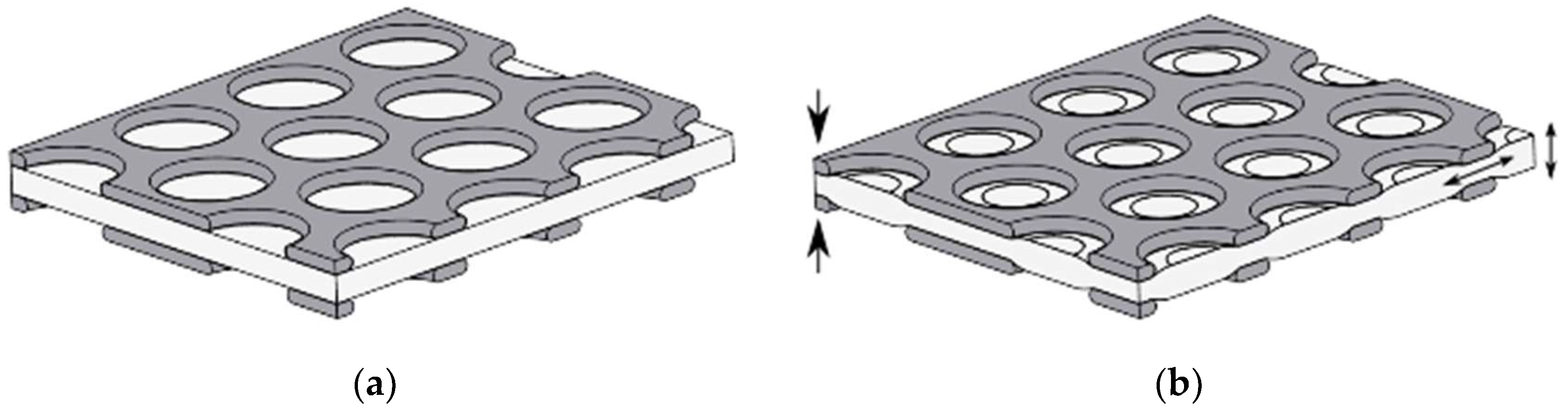
At Fraunhofer LBF a novel design approach for dielectric elastomer transducers was developed and tested in various applications [
12,
13,
18]. It is based on rigid metal electrodes comprising a microscopic hole pattern, allowing the elastomer to locally deform in these cavities when a high voltage signal is applied (see
Figure 1). To predict their deformation, the general theory developed for DEAP actuators can be used. At low frequency, the force per unit area that acts to squeeze the film is [
19]
where
is the force per unit area,
is the relative dielectric constant of the polymer,
is the dielectric constant of free space,
is the applied voltage and
is the film thickness. The actuation thickness strain resulting from the squeezing pressure is
where
is the strain along the thickness and
is the modulus of elasticity of the polymer. It is then clear then that there is a nonlinear relationship between the supply voltage and the sound pressure. The given expressions are obtained for ideal actuators with compliant electrodes subject to small quasi-static deformations. In the case of perforated rigid electrodes, the polymeric layer stiffness is linear only for very small deformations. Moreover, for harmonic displacements, the dynamics of the structures and the viscoelastic properties of the polymeric layer may be important in characterising the response of the actuator. The development of a dynamic model of perforated rigid electrodes DEAP actuator and their mechanical nonlinear response is out of the scope of this paper. However, the importance of their dynamics and their nonlinear response are here evaluated experimentally.
3. Experimental Investigations
Four separate experimental tests have been carried out to characterise the DEAP loudspeaker. In the next subsection, the manufacturing of the prototype and the powering requirement, common to all experiments are introduced. The following four subsection present configurations, results and discussions of each individual measurement setup. In particular, diaphragm displacement, bias and alternating voltage effect, sound pressure levels and directivity are described.
3.1. Loudspeaker Prototype Setup
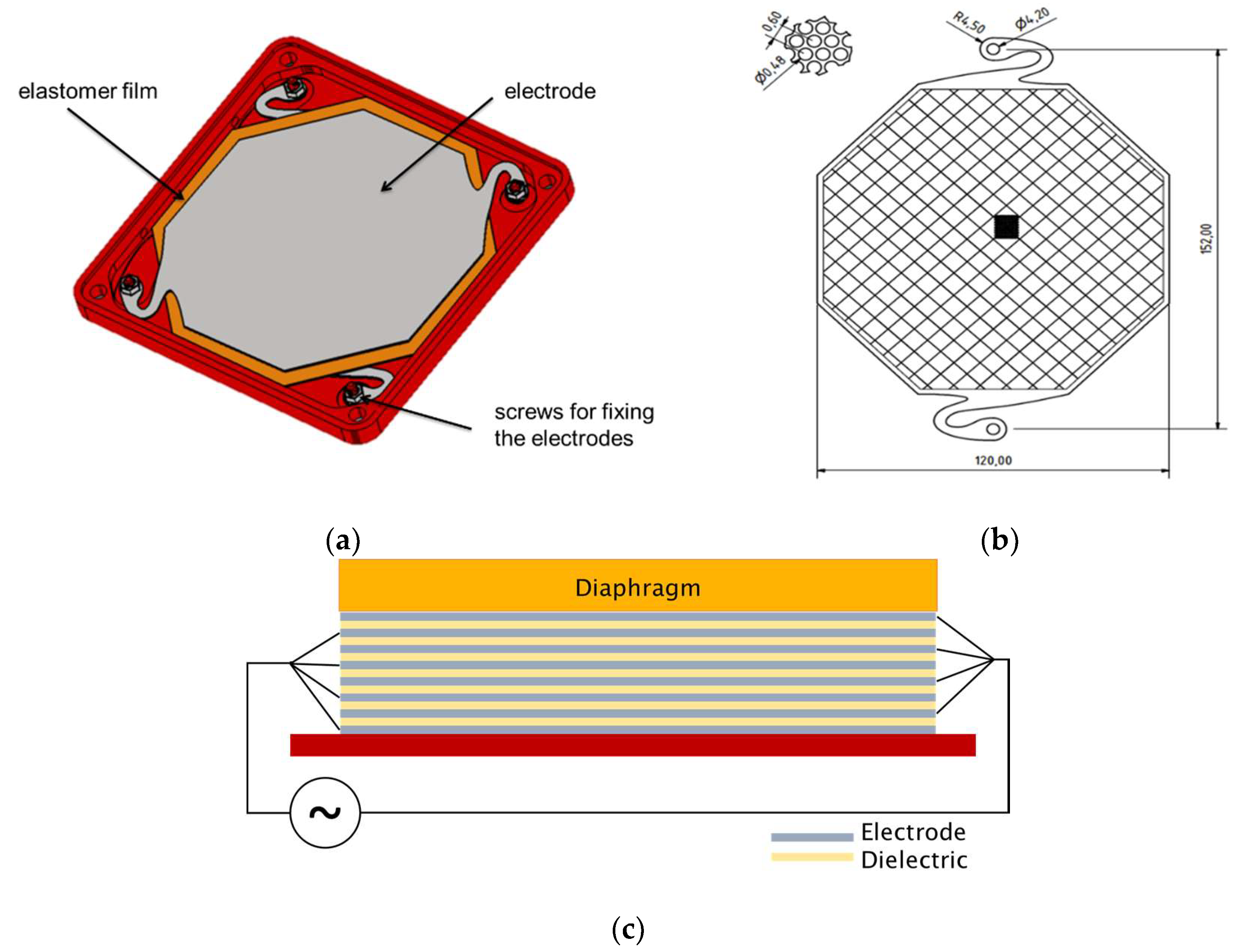
The loudspeaker shown in
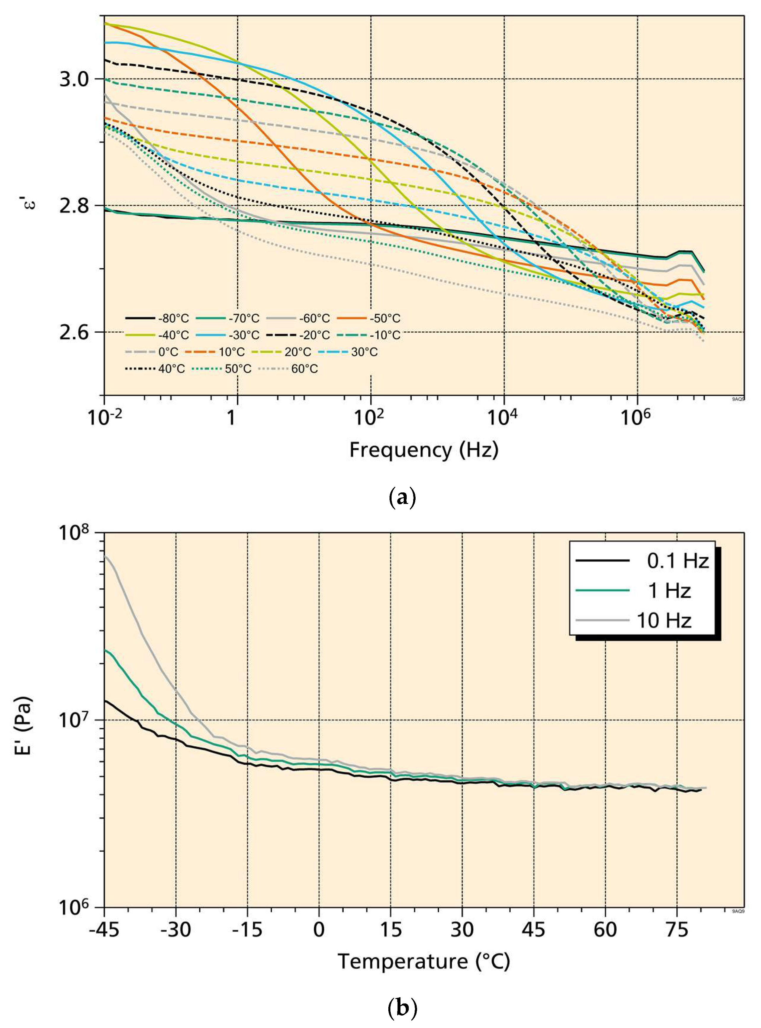
Figure 2 was obtained by stacking alternating layers of elastomer and perforated electrode. The elastomeric layers were made of natural rubber, Thera-Band extra thin Resistance Band. Its Young’s modulus was determined by a dynamic mechanical analysis (DMA) for various frequencies and temperatures (
Figure 3a). Its loss factor was determined to be 0.07 (at 10 Hz, 20 °C) and thus smaller than almost all other materials used for dielectric elastomers. The low damping helps in lowering mechanical and thermal losses for operation at high frequencies. Its relative dielectric permittivity was measured using dielectric relaxation spectroscopy (
Figure 3b).
The electrodes were stainless steel perforated plates, 0.03 mm thick. Circular perforations, obtained by etching, were 0.48 mm in diameter and 0.6 mm apart in a 60°-symmetric honeycomb formation, which gives a free area ratio of 58%. The electrodes were octagonally shaped with a total width of 120 mm and a longest diagonal of about 130 mm (see
Figure 2b).
Table 1 lists the overall physical properties of the electrode and elastomer.
The prototype tested in this work is made of 17 electrodes and 16 elastomer sheets made of natural rubber latex unless otherwise indicated. Electrodes were connected in parallel as shown in
Figure 2c. The capacitance of the DEAP loudspeaker is estimated as 156 pF using the properties from
Table 1.
Tests were carried out in the laboratory and in a semi-anechoic chamber at the University of Southampton. The DEAP loudspeaker was driven by a high voltage amplifier, Trek® 2220 (TREK, Inc., New York, NY, USA), capable of an output voltage of 2 kV up to 7.5 kHz. For safety, the DEAP loudspeaker was placed in a security switched box when operated in the laboratory. A voltage comparator was additionally used to avoid damage of the DEAP loudspeaker caused by accidental sparking.
To change the radiation properties of the loudspeaker, three different top layers (diaphragms), with different mechanical properties, were employed, as shown in
Figure 2c. In particular, an acrylic, an aluminium and a steel top layer were employed.
Table 1 shows the mechanical properties of the electrodes, elastomeric layers and additional diaphragm. Apart from the sizes, densities and Young’s moduli of the different layers, some dynamical properties have been calculated and reported to help in the interpretation of the experimental results. The disc natural frequency is the first natural frequency of a circular plate of a 60 mm radius,
, with the external edge in free boundary condition. The edge rise frequency is the frequency at which the wavelength of the bending wave,
, matches twice the width of the layer. The coincidence frequency is the frequency at which the bending wave speed in the layer matched the acoustic wave speed.
3.2. Laser Measurements of Surface Vibrations
Surface vibration was measured to evaluate the actuator authority. The diaphragm displacement at its centre was measured in the audible frequency range, 200 Hz to 20 kHz. A Polytec® PDV-100 laser vibrometer (Polytec GmbH, Waldbronn, Germany) was mounted at distance of 23 cm from the DEAP loudspeaker. Reflective tape was added to the clear plastic plate to aid measurement. The vibrometer internal low pass filter was set to 22 kHz. A Data Physics QUATTRO Dynamic Signal Analyser was used to collect surface vibration and supplied voltage and current. Sine sweeps with an 800 V offset and a 50 V alternated driving amplitude were employed to operate the DEAP loudspeaker. Continuous signals were chosen to reduce high frequency current spikes, which may lead to localised dielectric breakdown. An average of five tests was considered to calculate the transfer functions.
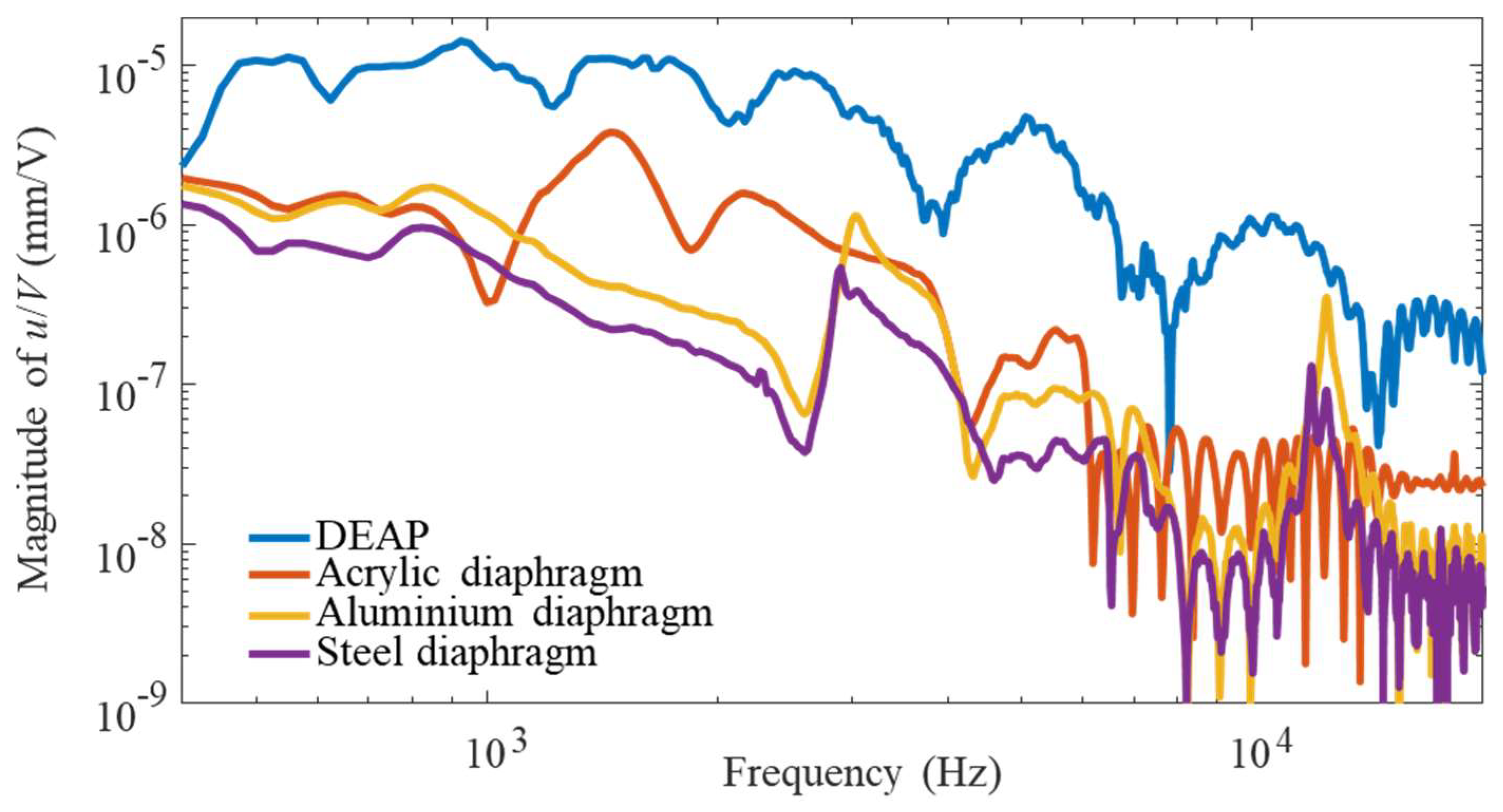
The measured transfer functions are shown in
Figure 4 where the displacement refers to the centre of the top moving layer. Measurements were also repeated with the three different diaphragms, of different masses, placed on top of the DEAP loudspeaker.
At low frequency, the response is constant with frequency. This region is controlled by Equation (2). At higher frequencies, the mass of the actuator becomes important and the measured displacement is reduced. This reduction is more pronounced with the use of top plates due to their relevant incremental mass. The reduction starts to appear after the first bounce resonance frequency and the additional mass of the top plate lower this natural frequency. At the same time, the stiffness region, which should not be affected by the additional mass of the top plate, shos a reduction. It is however likely that the stiffness of the actuator, partially due to the filling of the electrodes holes, acts in a nonlinear way and is affected by the pre-load due to the weight of the top plates.
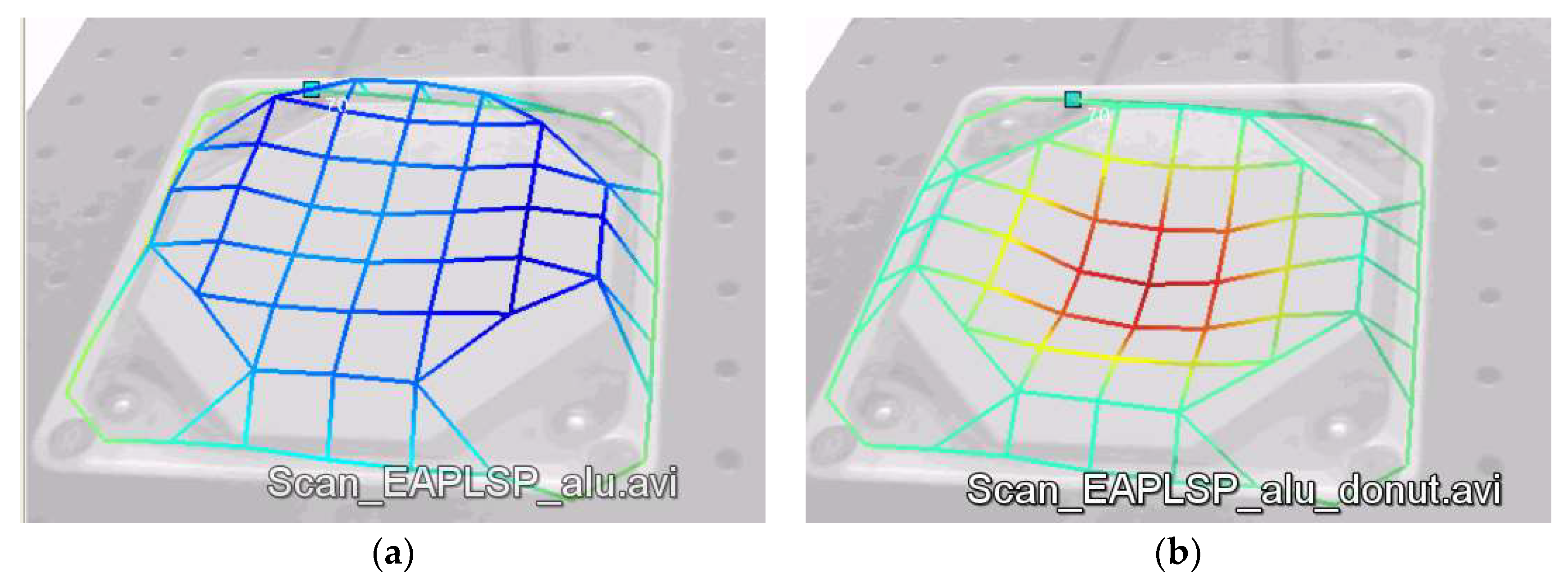
It is interesting to note that this measurement can be related to the volume velocity of the noise source in a baffled configuration. However, a decrement in the displacement in the centre of the loudspeaker does not mean that the noise radiated will diminish. In fact, the radiation characteristic of the DEAP loudspeaker depends on the full top layer deformation. Measurements with a scanning laser vibrometer allowed to visualise the modal response of the moving surface.
Figure 4 shows the measurement results of the top surface when the loudspeaker is driven with the aluminium diaphragm. For a driving modulated voltage at 1.6 kHz (see
Figure 5a) the electrode moves as a rigid body and we can assume that the loudspeaker will behave as a baffled rigid piston. This means that the sound pressure grows with frequency and the source is omnidirectional up to a cut-off frequency of 900 Hz (
= 1 with
= 6 cm).
Figure 4 shows no resonant behaviour in this frequency range. Above the cut-off frequency the omnidirectionality is lost and drops in the sound pressure can appear.
Figure 5b shows instead the deformation of the top diaphragm at 3 kHz. At this frequency, the rigid movement is lost and the diaphragm behaves as a vibrating plate.
Figure 4 shows that this frequency is the first resonant frequency of the plate. At this frequency and above, the radiation modes and efficiency become the driving factors.
3.3. Effects of Bias and Alternating Voltage
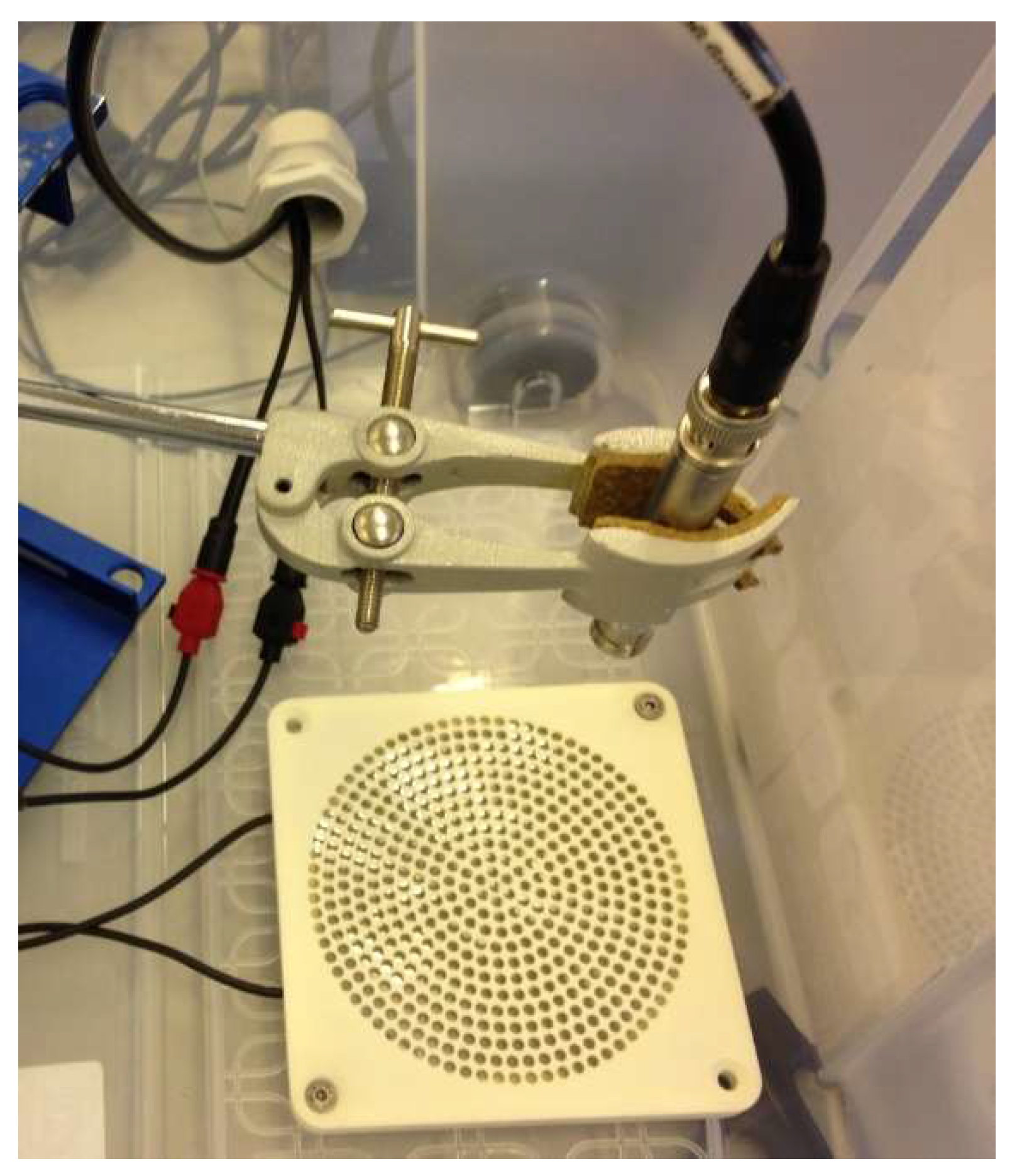
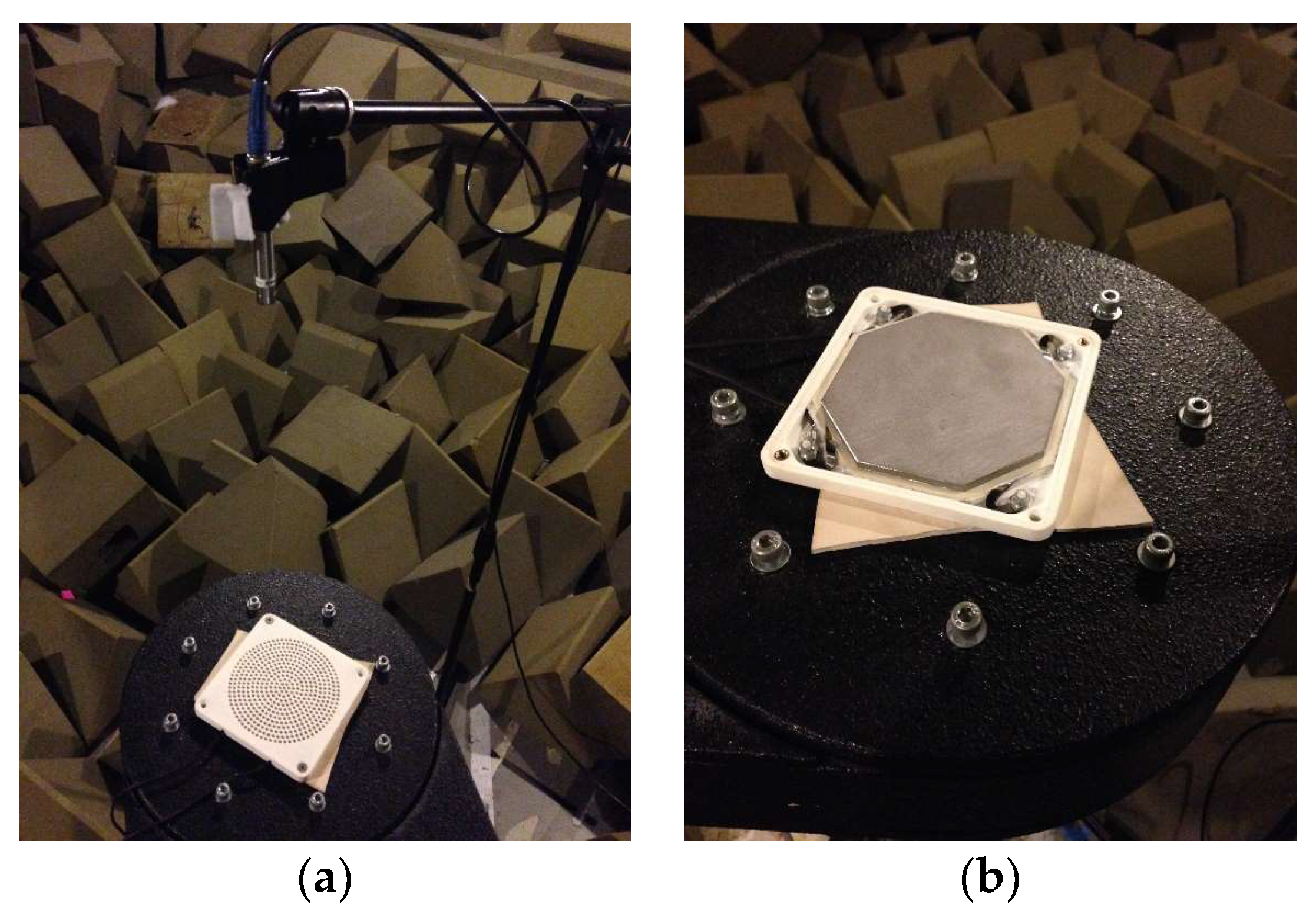
An initial experiment was carried out to determine the effect of bias (DC) and alternating (AC) voltage supply. The loudspeaker was placed inside a 75-litre plastic box with a PCB 387B02 microphone placed at distance of 18 cm on-axis to the centre of the DEAP loudspeaker. as shown in
Figure 6. The DEAP loudspeaker was driven by a 20-s sine sweep from 200 Hz to 20 kHz and transfer functions between pressure and voltage were calculated. In
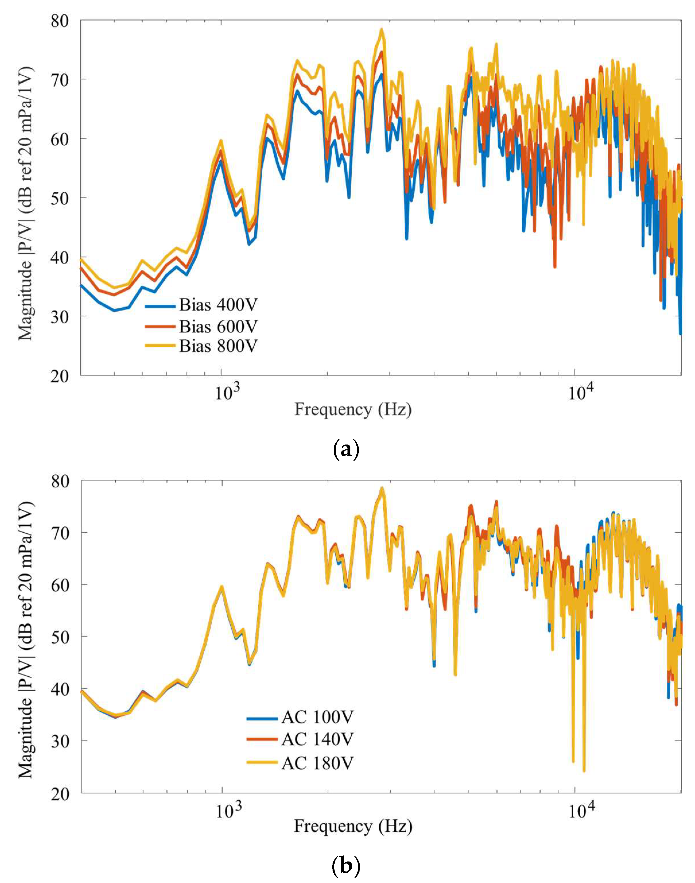
Figure 7a, the bias voltage is varied from 400 V to 800 V while the alternating voltage is kept constant at 100 V. The positive effect of the bias voltage can clearly be seen. Increasing the voltage, the slope in the curve voltage-displacement increases the effect of the alternating voltage. In
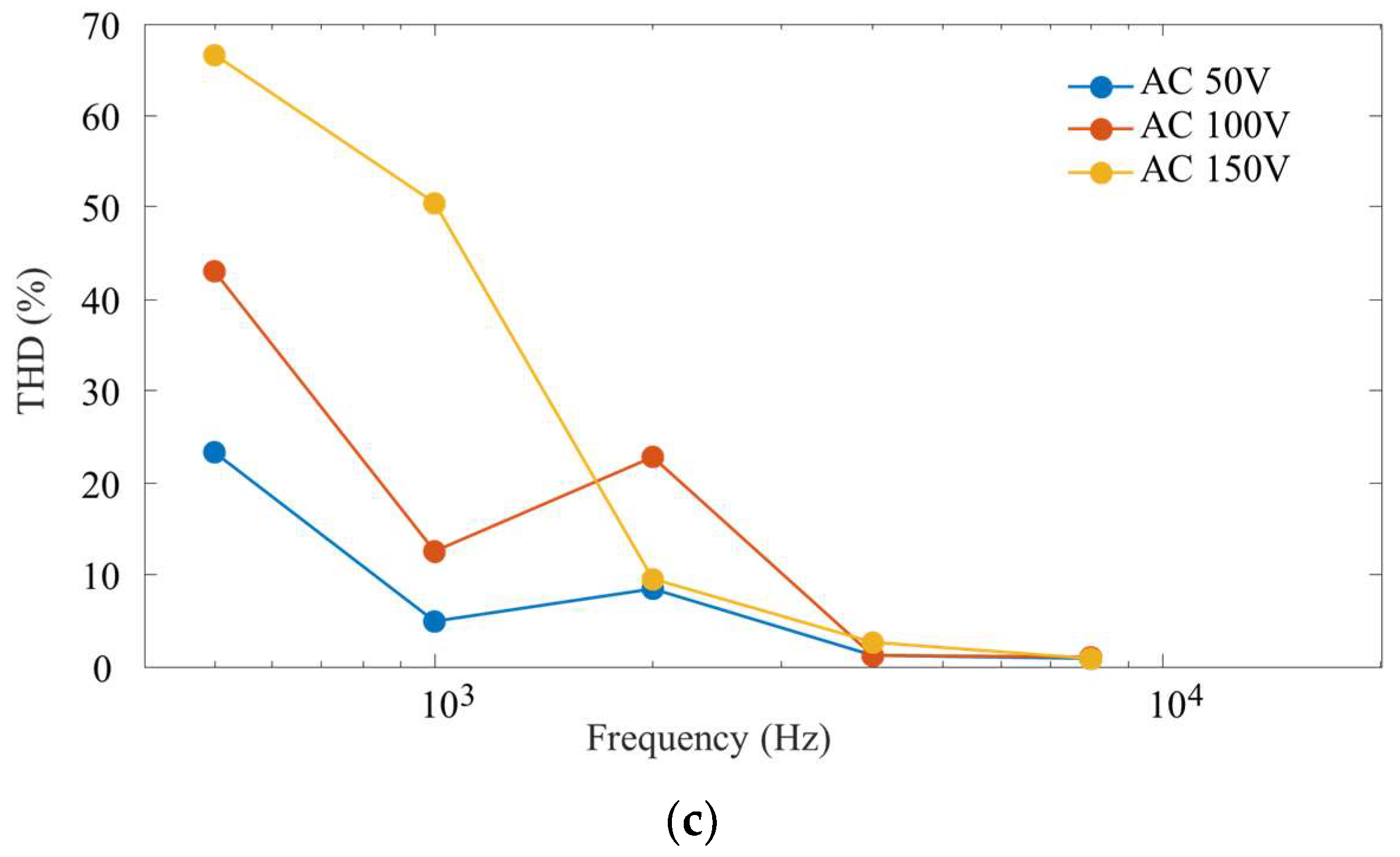
Figure 7b, the bias voltage is maintained at 800 V while the alternating voltage is varied between 100 V and 180 V. There are no apparent effects in the magnitude of the acoustic pressure recorded. Some discrepancy is observed, however, in the higher frequency range. Increasing the alternating voltage, a large section of the voltage-displacement curve is covered. This means that the DEAP loudspeaker nonlinearity increases, thus increasing the loudspeaker distortion. This is tested by looking at the total harmonic distortion,
.
was calculated using the first five harmonics at each measurement frequency using the following equation:
where
is the fundamental component and
are higher order components. Five pure tone sine waves were generated at 500 Hz, 1 kHz, 2 kHz, 4 kHz and 8 kHz. DC bias was kept constant at 800 V. For each measurement, the power spectrum was obtained to identify the amplitude of the harmonic.
Figure 7c shows that an increase in the alternating voltage increases the distortion of the DEAP.
As a first conclusion, it seems that increasing the bias voltage is beneficial while the alternating voltage should be limited to avoid nonlinear distortion in the emitted sound. The nonlinearity is intrinsic in DEAP actuators and several studies have looked at reducing its influence, by shaping the input voltage or using a push–pull configuration [
1,
18,
20]. In this paper, none of these methods has been adopted but the nonlinearity has been minimised by keeping the alternating voltage low.
3.4. Acoustic Measurement of Sound Pressure
Experiments were conducted in a small semi-anechoic chamber at the University of Southampton to obtain on-axis frequency responses and directivity measurements. The effect of the loudspeaker cover, the loudspeaker diaphragm and the loudspeaker support were also investigated.
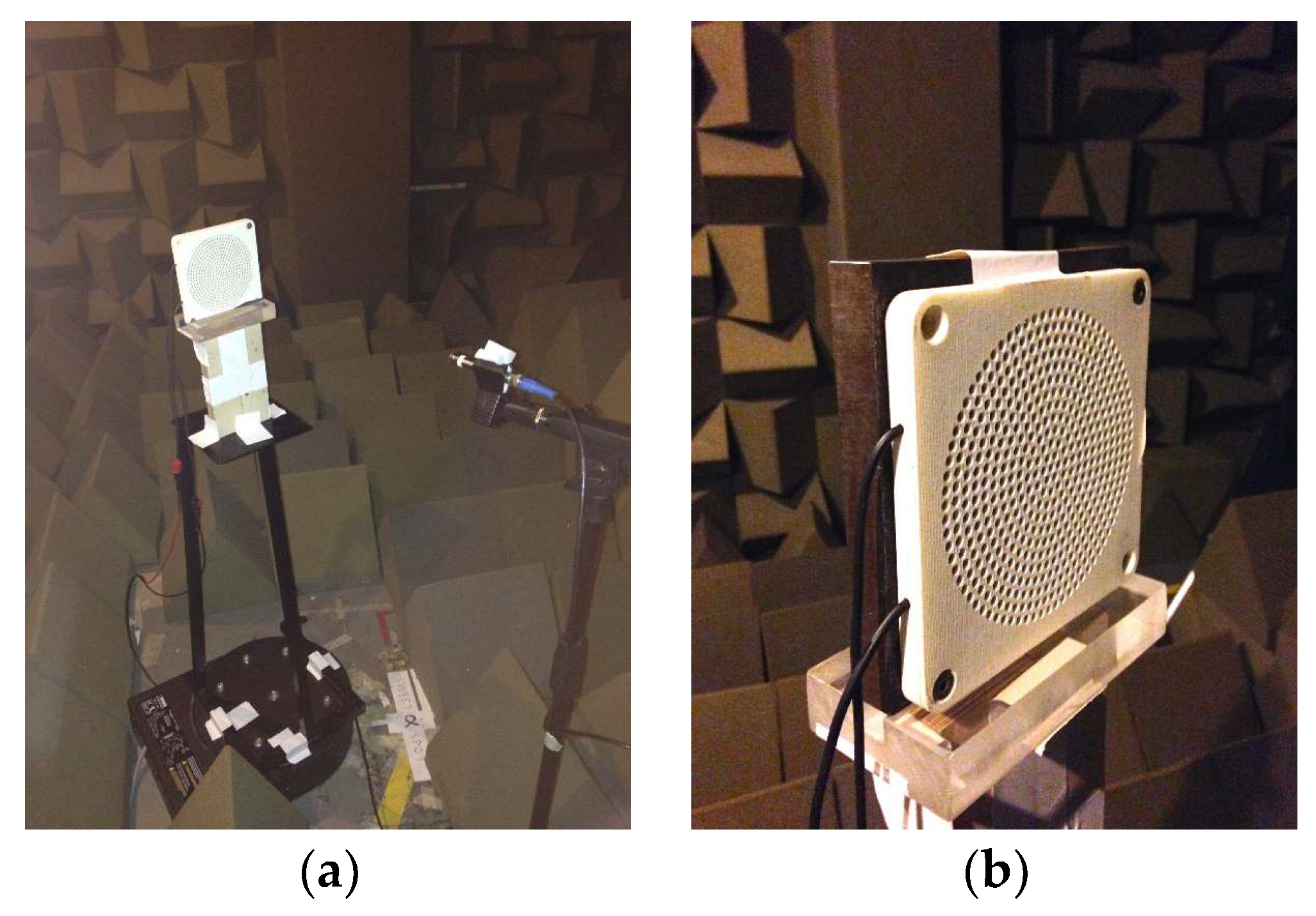
As shown in
Figure 8, the DEAP loudspeaker was placed in the centre of the anechoic chamber flat, parallel to the floor on a stand at a height of approximately 1.2 m from the ground. The microphone was placed on-axis at 50 cm from the DEAP loudspeaker. Only the DEAP loudspeaker and the microphone were present in the chamber during measurements while the amplifier and other sources of noise were kept outside. The amplifier’s voltage and current monitor outputs were recorded to obtain a simultaneous pressure, voltage and current reading for every measurement. A 20-s sine sweep from 200 Hz to 20 kHz was generated as the test signal to measure the DEAP loudspeaker’s response. As per the preliminary test conclusions, the DC bias was set to 800 V and the AC voltage to 50 V. Five measurements were made at a 51.2 kHz sampling frequency and power spectral densities of the pressure, voltage and current obtained for each measurement and averaged. A 1024-point FFT, an equivalent Hamming window and a fifty-percent overlap were chosen, giving a frequency resolution of 25 Hz, to limit random error and provide adequate smoothing to make the data clearer.
The test was repeated with the speaker’s enclosure cover removed to see its effect on the acoustical emissions. Three more sets of measurements were repeated with plates of different materials being placed directly on the speaker’s DE-electrode stack. Such tests were done to investigate the effect of diaphragm material on the DEAP loudspeaker performances. Properties of the additional diaphragm material are reported in
Table 1.
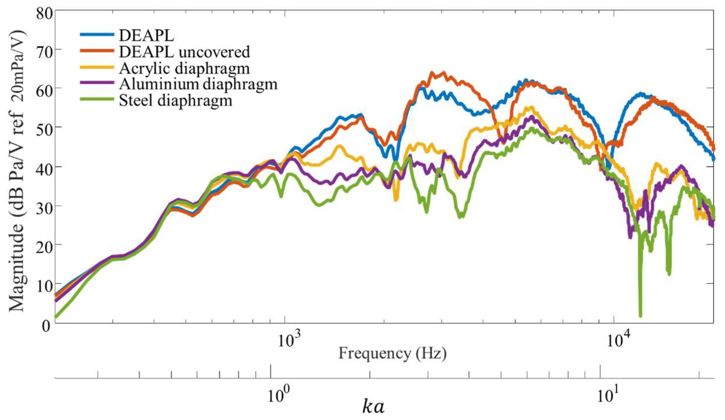
Figure 9 shows the transfer function between the sound pressure level recorded and the supplied voltage. The characteristic response shows two distinct areas. At low frequency, the response is characterised by a growing sound pressure level with a slope of about 40 dB per decades. At higher frequencies, the sound pressure level is instead flat. This response can be physically interpreted. At low frequency, the diaphragm of the DEAP loudspeaker moves as a rigid surface, that is the loudspeaker behaves as a rigid piston. In addition, at low frequency, acoustic wavelength is large with respect to the loudspeaker dimensions and the response is equivalent to that of a monopole. As shown below, this behaviour is respected in the directivity plots which show omnidirectionality at low frequency. A rigid piston stops to behave as a monopole when
, where
is the wavenumber,
is the radius of the piston,
c is the wavespeed of sound in air and
is the frequency of oscillation. Since
is approximately 6 cm, this threshold frequency is about 900 Hz, as indicated in
Figure 9. The threshold matches the experimental results for the three tests with additional diaphragms. The tests with additional diaphragms show a higher threshold at 1800 Hz. This behaviour is in accordance with the prediction of Aarts et al. [
21], who showed that the behaviour of a resilient disk is different from that of a rigid piston and that its transition frequency is higher. Intuitively, a resilient disk assumes a curved shape which resembles more to a spherical source so that the similarity with a point source is maintained longer.
For , the DEAP loudspeaker starts behaving as a piston. However, this piston is not rigid but compliant. This means that the expected response should be flat but with up and downs due to the modal response. Given the distance of the microphone from the loudspeaker and the frequency range of interest it is excluded the drops being due to hydrodynamic nearfield.
The loudspeaker behaves as an ideal rigid piston, with a clear threshold at 900 Hz, when an additional diaphragm is added on top of the top electrode. However, the material of the diaphragm has a minor effect on the total response. The overall response is dependent on the actual mass of the top layer and the high frequency region seems to be mostly mass-controlled. Although the coincidence frequency decreases from acrylic to aluminium and steel plate there is no evident effect in the results of
Figure 9. It has to be noted that the weight of the additional diaphragm increases the pre-compression of the elastomer layers and potentially increases the nonlinearity of the system.
Looking at the effect of the cover on the radiated sound power, it is clear that the effect of the cover is minimal but may become of importance in the design of high quality loudspeakers.
3.5. Acoustic Measurement of Directivity
In the small anechoic chamber, the DEAP loudspeaker was placed on a stand mounted onto an ET250-3D electronic turntable, as shown in
Figure 10, in the centre of the chamber at a height of approximately 1.2 m from the floor. The microphone was placed at a distance of 50 cm from the on-axis 0° position relative to the turntable. The turntable was set to turn in steps of 10°. The DC bias and AC voltage remain the same, 800 V and 50 V, respectively. A 10 s measurement was recorded for every turn in a full 360° revolution to compile a single set of data. Sets of directivity measurements were carried out for single pure tone frequencies of 500 Hz, 1 kHz, 2 kHz, 4 kHz and 8 kHz. Measurements were collected and processed in Matlab. For each measurement, a power spectral density was obtained and an average sound pressure level computed for each angle of every octave frequency. Sound pressure has not been normalised to show the difference between the two configurations. The experiment was repeated twice to show the effect mounting has on the DEAP loudspeaker performance as shown in
Figure 11. The test with the DEAP loudspeaker back not supported was followed by a test with its back rigidly supported by a 1.5 kg steel bracket.
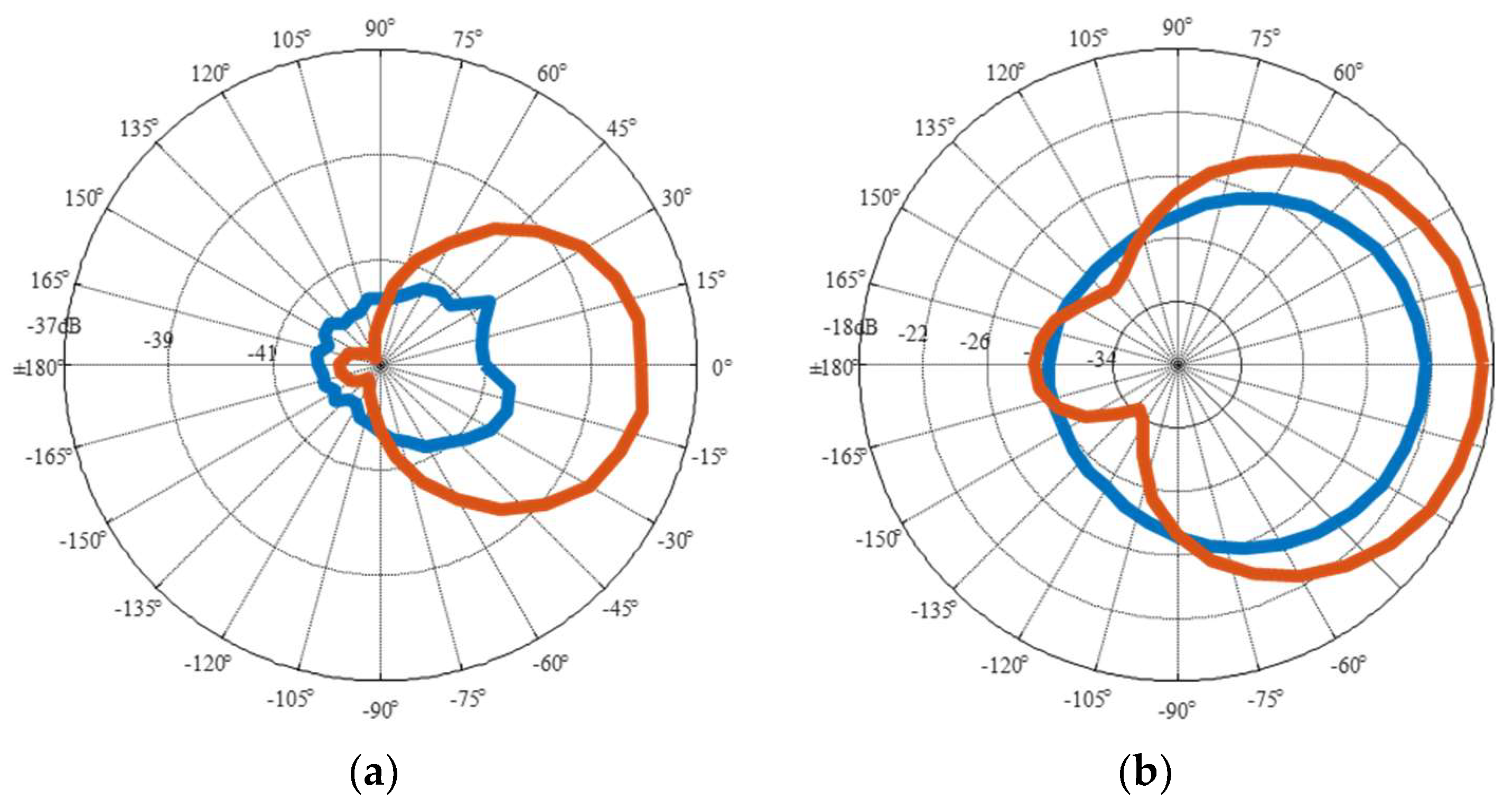
The directivity plots of
Figure 11 change with frequency. When the DEAP loudspeaker back is not supported, blue lines, both the front and back of the loudspeaker generate sound. Probably their motion is in opposition of phase, so that they generate sound similarly to a pulsating sphere. For this reason, the response is almost omnidirectional. This behaviour is very clear at low frequencies. In the middle frequency range this behaviour changes due to the modal deformation of the diaphragm. The test with the rigid support shows a response similar to the one expected from a baffled rigid piston. At low frequency, it is similar to that of a monopole very close to the baffle. At higher frequencies, the directionality shows lobes with maxima on the axis of the loudspeaker. At high frequencies, however, the performance drops, as shown in
Figure 8.
4. Conclusions
In this paper, a novel extremely flat loudspeaker which uses dielectric elastomers and its experimental characterisation has been presented. This concept features elastomeric layers of natural rubber and rigid perforated metal electrodes as transduction mechanism. It is advantageous regarding weight, design space, design flexibility and integration potential compared to conventional loudspeaker concepts. An extensive experimental characterisation of the loudspeaker regarding vibration and acoustic behaviour was performed in an anechoic chamber to exclude unwanted acoustic interference. On axis sound pressure level and directivity were measured. Both show the potential of this concept for high frequency applications. Nevertheless, nonlinearities which are inherent for this kind of actuators were also investigated and quantified by total harmonic distortion. An increased distortion is observed for high amplitudes of alternating voltage and low driving frequencies. Different diaphragms were tested showing a transition in behaviour from rigid piston to resilient disk with respect to frequency.
The developed loudspeaker has promising acoustic characteristics but the intrinsic nonlinearities in the loudspeaker have to be overcome before any commercial application can be taken into consideration.


