The Effects of Structure Thickness, Air Gap Thickness and Silicon Type on the Performance of a Horizontal Electrothermal MEMS Microgripper


Abstract
:1. Introduction
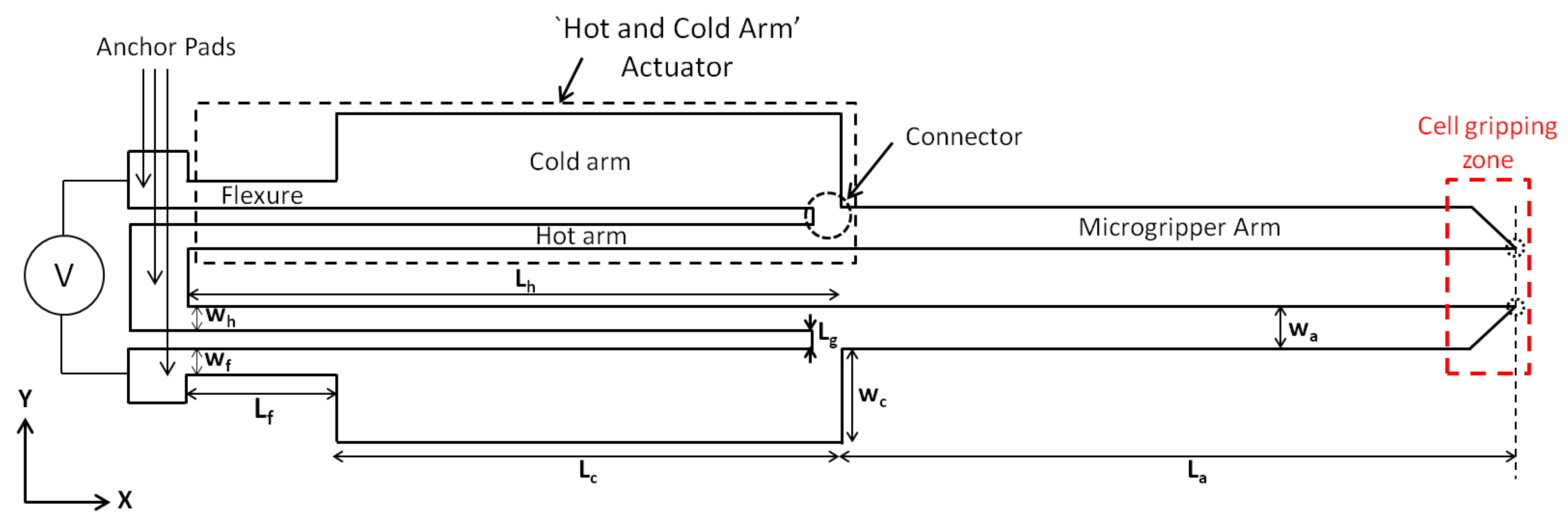
2. Microgripper Design Variants and Principle of Operation
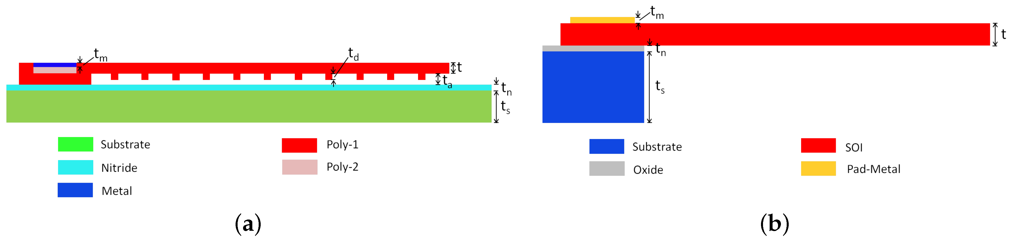
3. Fabrication Processes
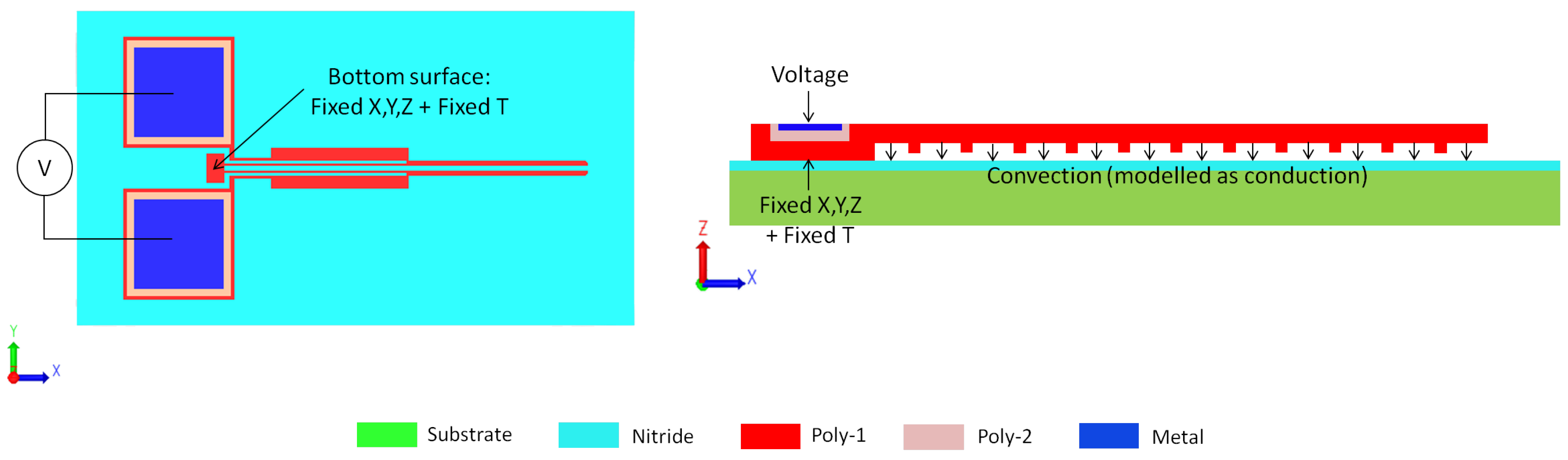
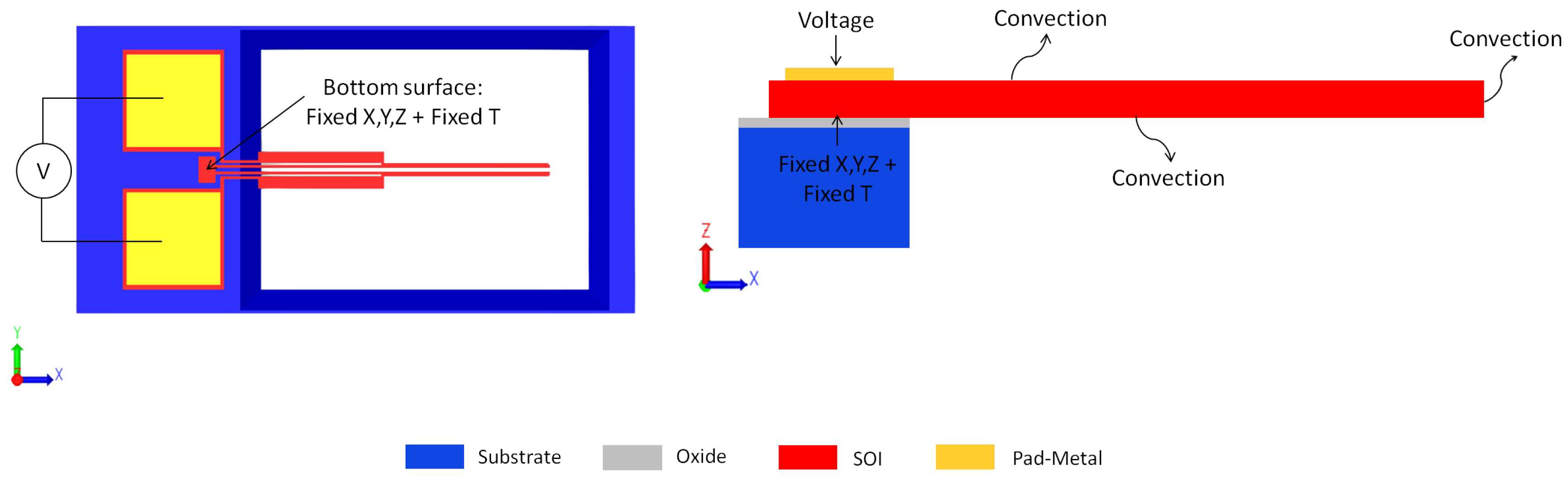
4. Numerical Models
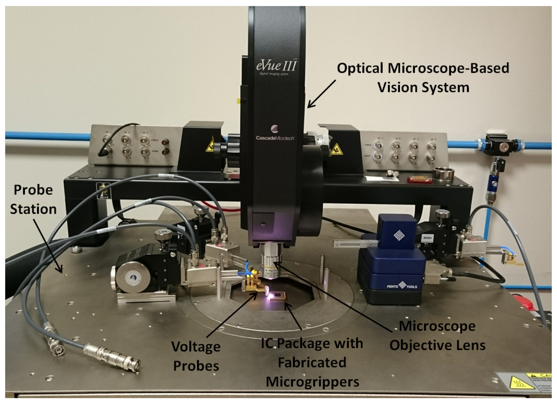
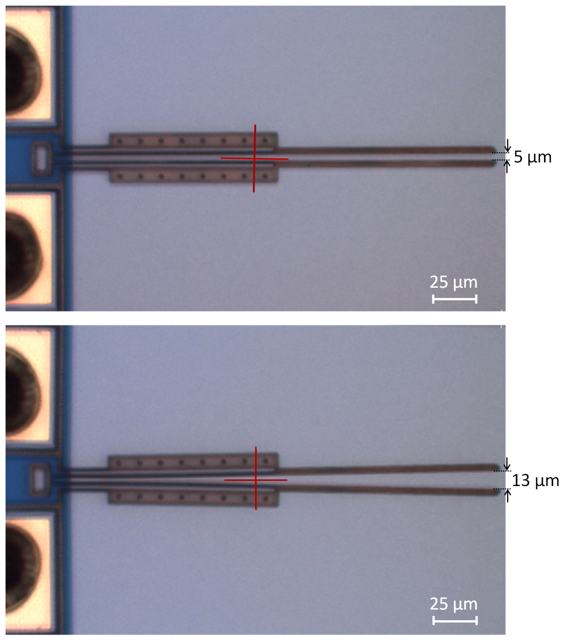
5. Experimental Setup
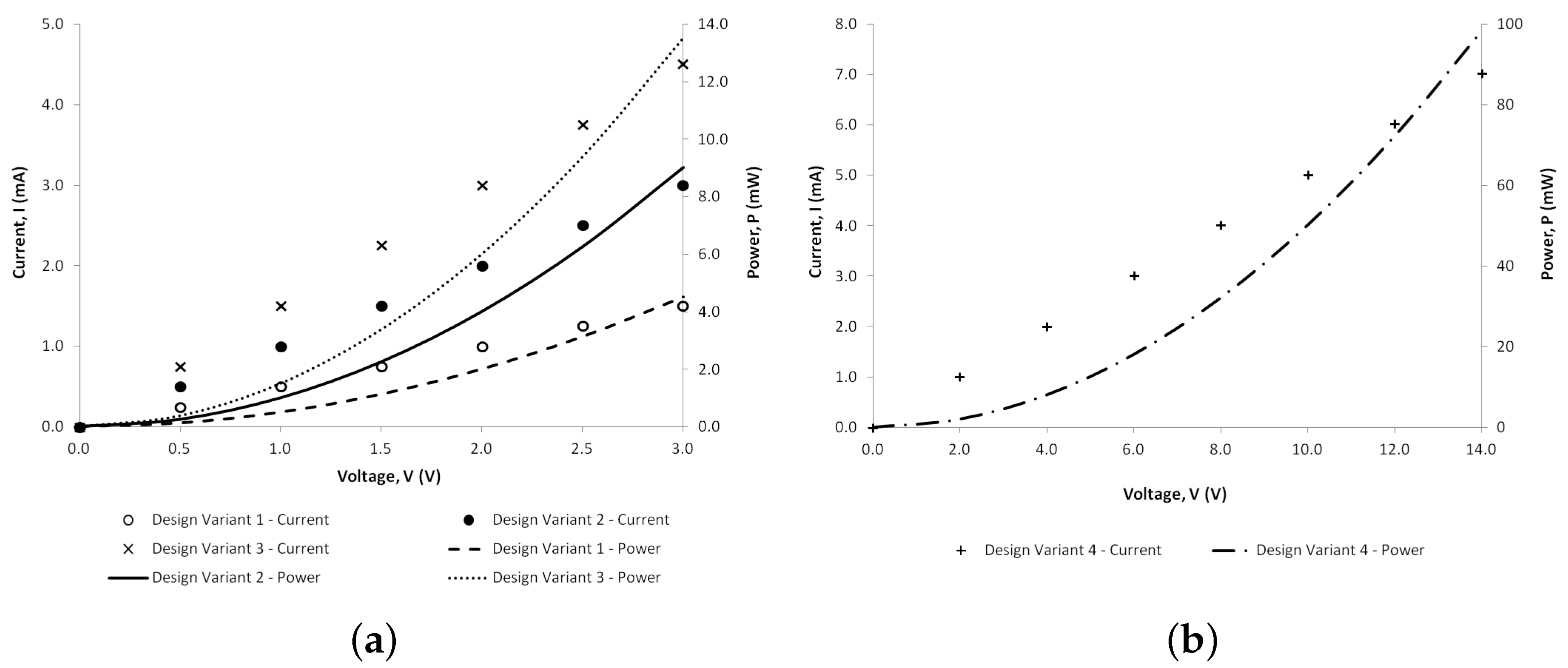
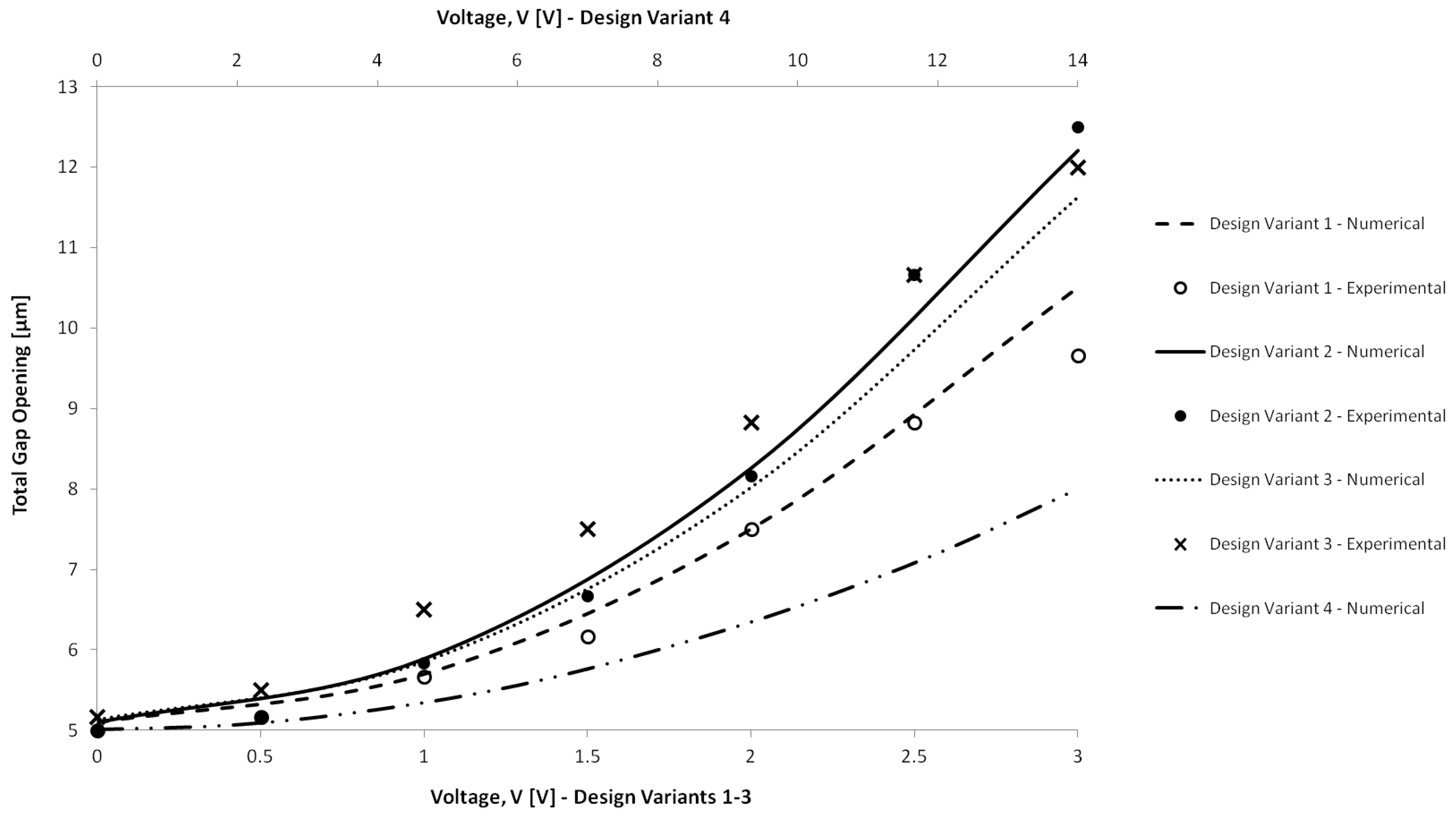
6. Results and Discussion
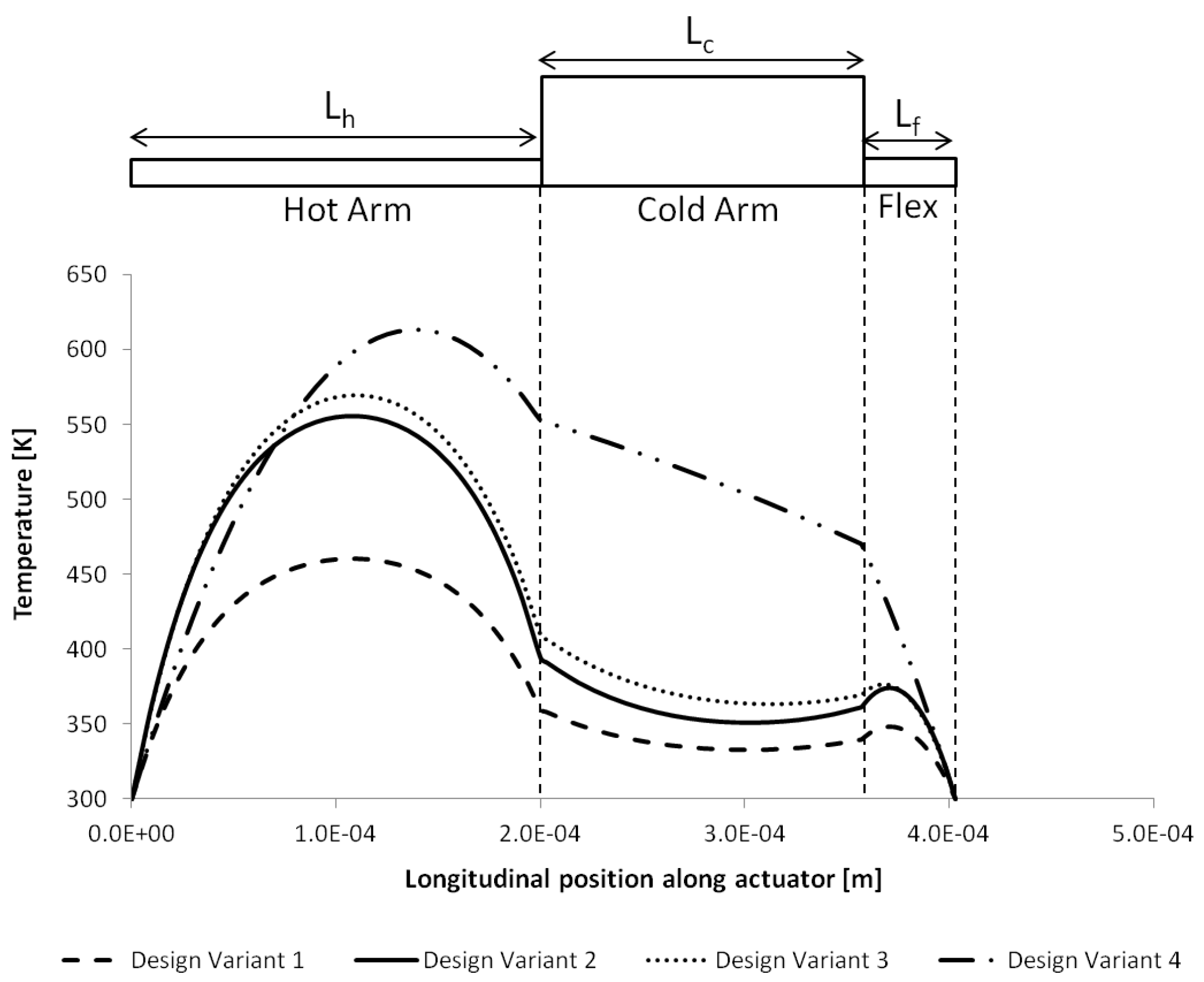
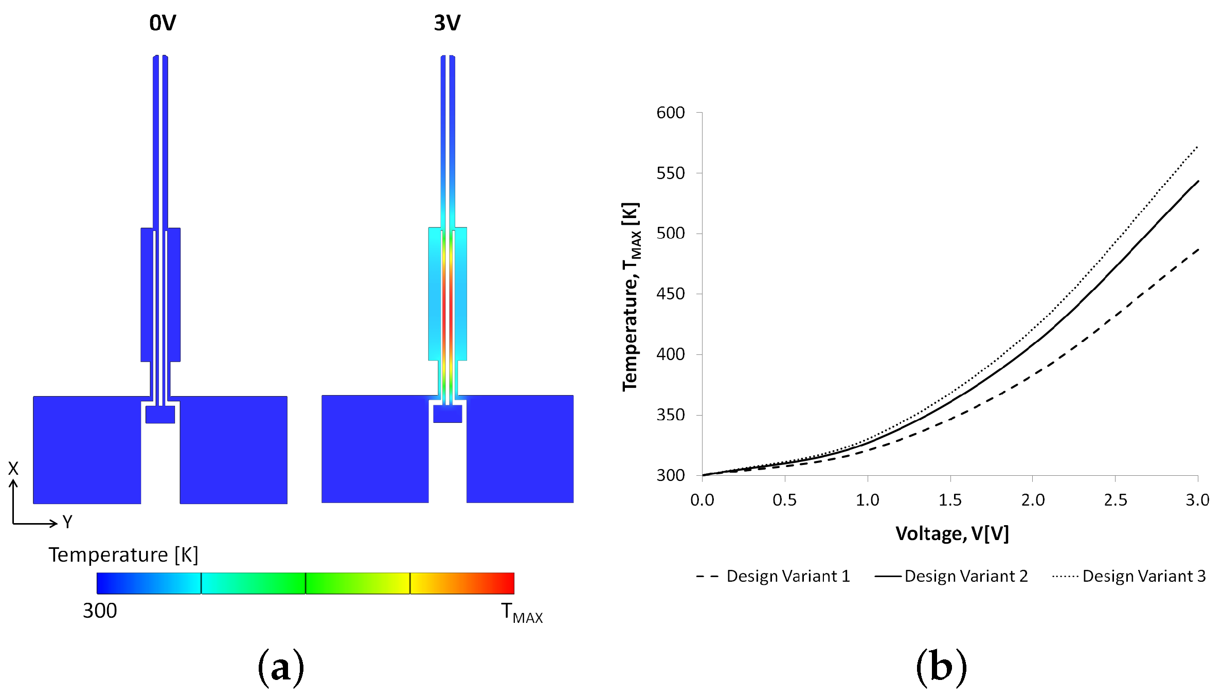
6.1. Thermal Analyses
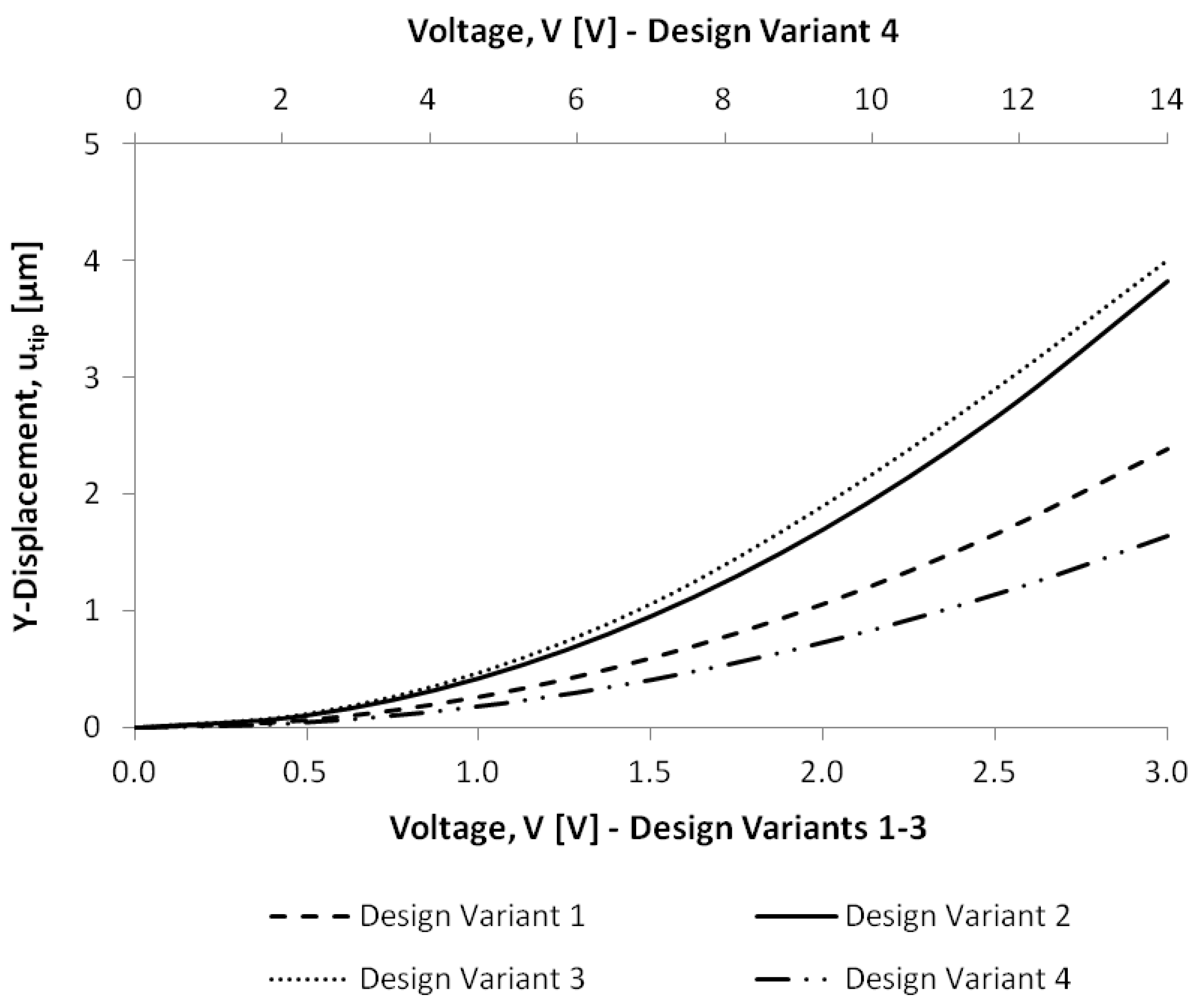
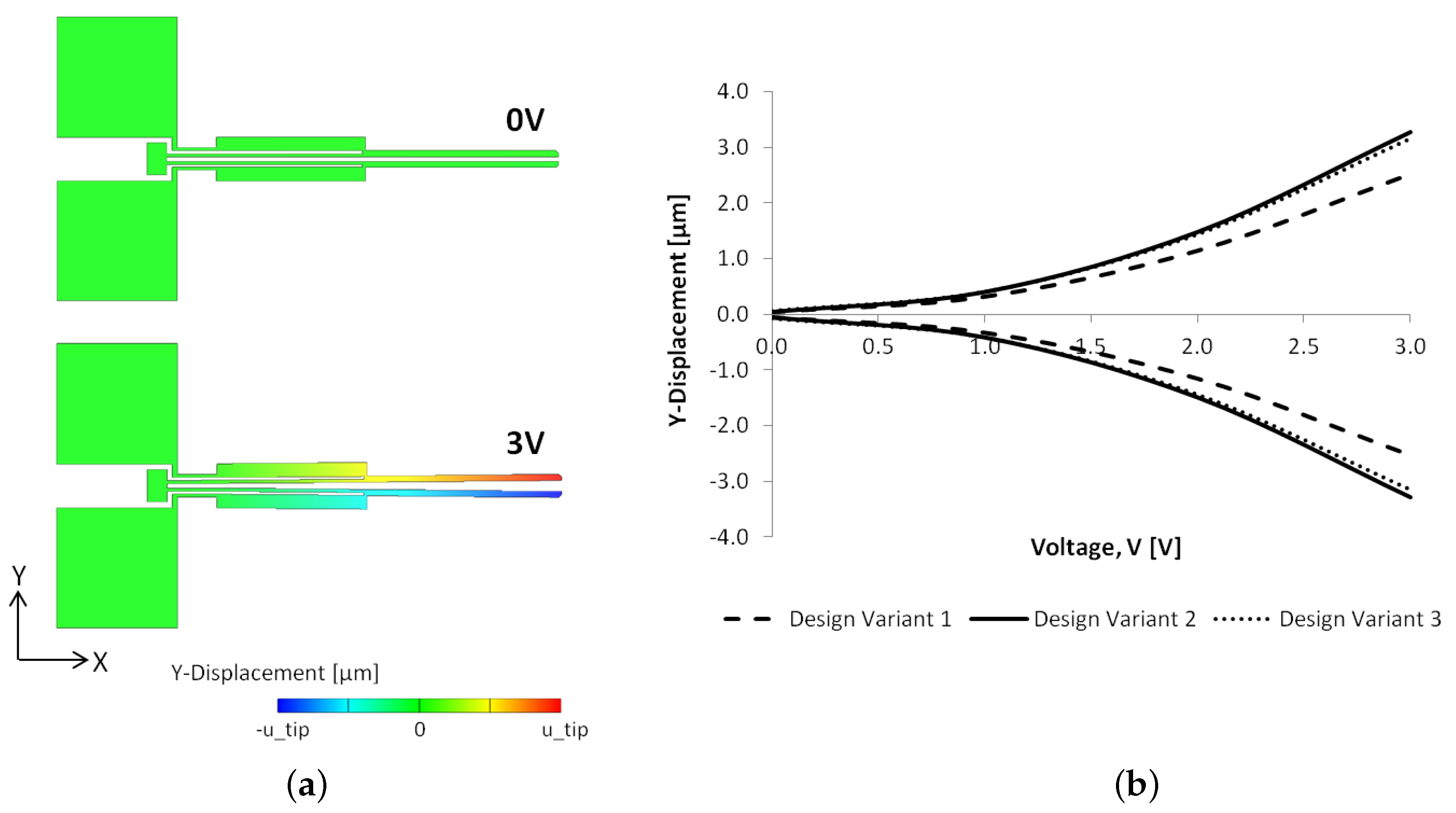
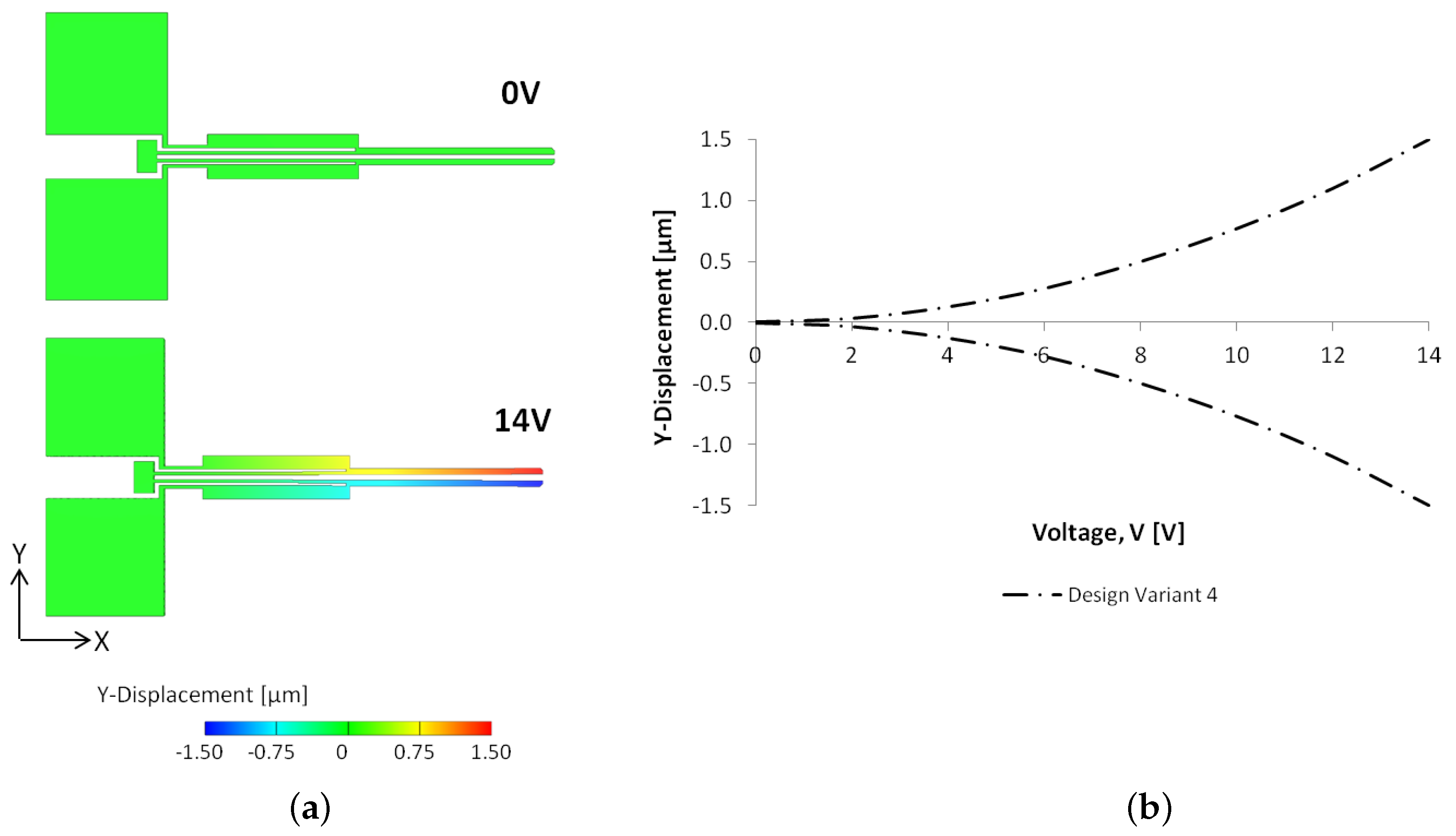
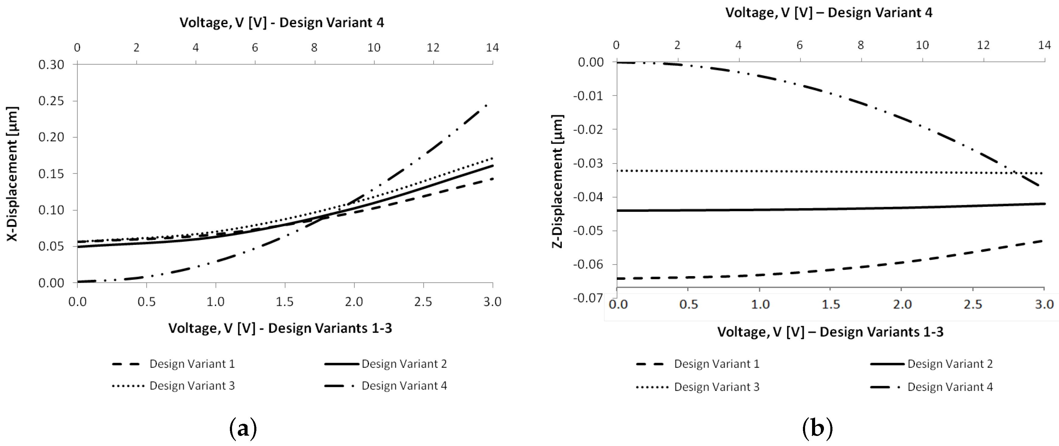
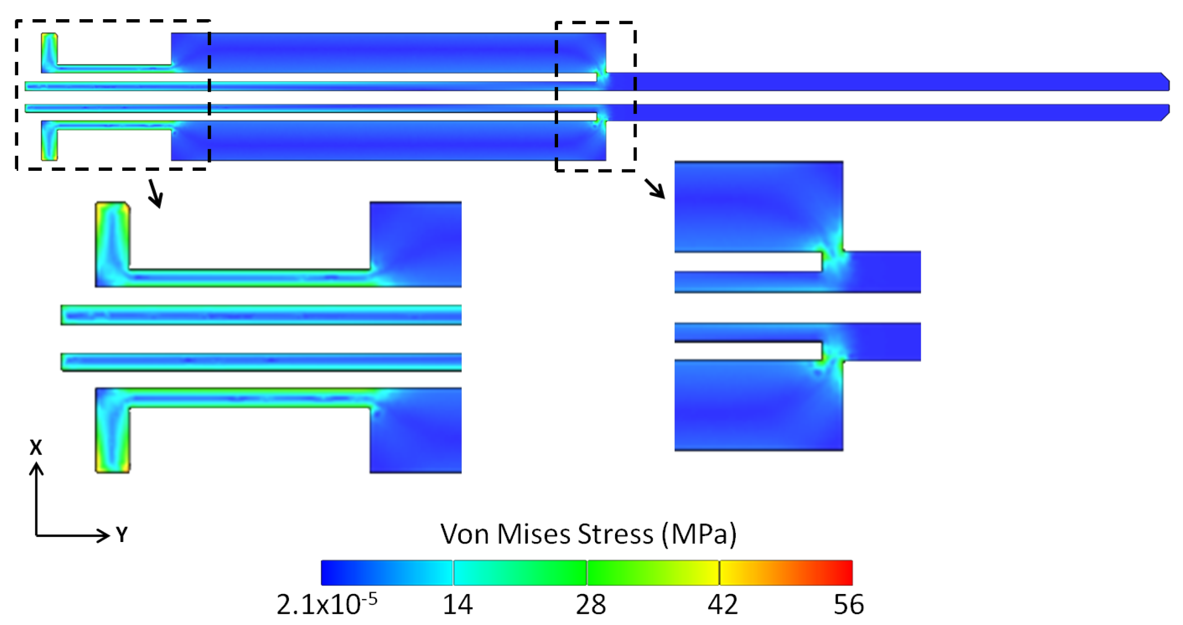
6.2. Structural Analyses
7. Conclusions
Author Contributions
Funding
Acknowledgments
Conflicts of Interest
References
- Zhang, R.; Chu, J.; Wang, H.; Chen, Z. A multipurpose electrothermal microgripper for biological micro-manipulation. Microsyst. Technol. 2013, 19, 89–97. [Google Scholar] [CrossRef]
- Verotti, M.; Dochshanov, A.; Belfiore, N.P. Compliance synthesis of CSFH MEMS-based microgrippers. J. Mech. Des. Trans. ASME 2017, 139, 022301. [Google Scholar] [CrossRef]
- Di Giamberardino, P.; Bagolini, A.; Bellutti, P.; Rudas, I.J.; Verotti, M.; Botta, F.; Belfiore, N.P. New MEMS tweezers for the viscoelastic characterization of soft materials at the microscale. Micromachines 2017, 9, 15. [Google Scholar] [CrossRef]
- Kim, K.; Liu, X.; Zhang, Y.; Sun, Y. Nanonewton force-controlled manipulation of biological cells using a monolithic MEMS microgripper with two-axis force feedback. J. Micromech. Microeng. 2008, 18, 055013. [Google Scholar] [CrossRef]
- Kim, K.; Liu, X.; Zhang, Y.; Cheng, J.; Yu, W.X.; Sun, Y. Elastic and viscoelastic characterization of microcapsules for drug delivery using a force-feedback MEMS microgripper. Biomed. Microdevices 2009, 11, 421–427. [Google Scholar] [CrossRef] [PubMed]
- Solano, B.; Wood, D. Design and testing of a polymeric microgripper for cell manipulation. Microelectron. Eng. 2007, 84, 1219–1222. [Google Scholar] [CrossRef]
- Iamoni, S.; Somà, A. Design of an electro-thermally actuated cell microgripper. Microsyst. Technol. 2014, 20, 869–877. [Google Scholar] [CrossRef]
- Cecchi, R.; Verotti, M.; Capata, R.; Dochshanov, A.; Broggiato, G.B.; Crescenzi, R.; Balucani, M.; Natali, S.; Razzano, G.; Lucchese, F.; et al. Development of micro-grippers for tissue and cell manipulation with direct morphological comparison. Micromachines 2015, 6, 1710–1728. [Google Scholar] [CrossRef]
- Potrich, C.; Lunelli, L.; Bagolini, A.; Bellutti, P.; Pederzolli, C.; Verotti, M.; Belfiore, N.P. Innovative silicon microgrippers for biomedical applications: Design, mechanical simulation and evaluation of protein fouling. Actuators 2018, 7, 12. [Google Scholar] [CrossRef]
- Ivanova, K.; Ivanov, T.; Badar, A.; Volland, B.E.; Rangelow, I.W.; Andrijasevic, D.; Sümecz, F.; Fischer, S.; Spitzbart, M.; Brenner, W.; et al. Thermally driven microgripper as a tool for micro assembly. Microelectron. Eng. 2006, 83, 1393–1395. [Google Scholar] [CrossRef]
- Zhang, Y.; Chen, B.K.; Liu, X.; Sun, Y. Autonomous robotic pick-and-place of microobjects. IEEE Trans. Robot. 2010, 26, 200–207. [Google Scholar] [CrossRef]
- Hamedi, M.; Vismeh, M.; Salimi, P. Design, analysis and fabrication of silicon microfixture with electrothermal microclamp cell. Microelectron. Eng. 2013, 111, 160–165. [Google Scholar] [CrossRef]
- Verotti, M.; Dochshanov, A.; Belfiore, N.P. A comprehensive survey on microgrippers design: Mechanical structure. J. Mech. Des. 2017, 139, 060801. [Google Scholar] [CrossRef]
- Jia, Y.; Xu, Q. MEMS microgripper actuators and sensors: The state-of-the-art survey. Recent Patents Mech. Eng. 2013, 6, 132–142. [Google Scholar] [CrossRef]
- Yang, S.; Xu, Q. A review on actuation and sensing techniques for MEMS-based microgrippers. J. Micro-Bio Robot. 2017, 13, 1–14. [Google Scholar] [CrossRef]
- Nguyen, N.-T.; Ho, S.-S.; Low, C.L. A polymeric microgripper with integrated thermal actuators. J. Microelectromech. Syst. 2004, 14, 969–974. [Google Scholar] [CrossRef]
- Somà, A.; Iamoni, S.; Voicu, R.; Müller, R.; Al-Zandi, M.H.M.; Wang, C. Design and experimental testing of an electro-thermal microgripper for cell manipulation. Microsyst. Technol. 2018, 24, 1053–1060. [Google Scholar] [CrossRef]
- Solano, B.; Merrell, J.; Gallant, A.; Wood, D. Modelling and experimental verification of heat dissipation mechanisms in an su-8 electrothermal microgripper. Microelectron. Eng. 2014, 124, 90–93. [Google Scholar] [CrossRef] [Green Version]
- Al-Zandi, M.H.M.; Wang, C.; Voicu, R.; Müller, R. Measurement and characterisation of displacement and temperature of polymer based electrothermal microgrippers. Microsyst. Technol. 2018, 24, 379–387. [Google Scholar] [CrossRef]
- Dochshanov, A.; Verotti, M.; Belfiore, N.P. A comprehensive survey on microgrippers design: Operational strategy. J. Mech. Des. 2017, 139, 070801. [Google Scholar] [CrossRef]
- Kim, C.-J.; Pisano, A.P.; Muller, R.S. Silicon-processed overhanging microgripper. J. Microelectromech. Syst. 1992, 1, 31–36. [Google Scholar] [CrossRef]
- Bagolini, A.; Ronchin, S.; Bellutti, P.; Chistè, M.; Verotti, M.; Belfiore, N.P. Fabrication of novel MEMS microgrippers by deep reactive ion etching with metal hard mask. J. Microelectromech. Syst. 2017, 26, 7920329. [Google Scholar] [CrossRef]
- Wierzbicki, R.; Houston, K.; Heerlein, H.; Barth, W.; Debski, T.; Eisinberg, A.; Menciassi, A.; Carrozza, M.C.; Dario, P. Design and fabrication of an electrostatically driven microgripper for blood vessel manipulation. Microelectron. Eng. 2006, 83, 1651–1654. [Google Scholar] [CrossRef]
- Xu, Q. Design, Fabrication, and testing of an MEMS microgripper with dual-axis force sensor. IEEE Sens. J. 2015, 15, 7150331. [Google Scholar] [CrossRef]
- Cauchi, M.; Grech, I.; Mallia, B.; Mollicone, P.; Sammut, N. Analytical, Numerical and Experimental Study of a Horizontal Electrothermal MEMS Microgripper for the Deformability Characterisation of Human Red Blood Cells. Micromachines 2018, 9, 108. [Google Scholar] [CrossRef]
- Feng, Y.-Y.; Chen, S.-J.; Hsieh, P.-H.; Chu, W.-T. Fabrication of an electro-thermal micro-gripper with elliptical cross-sections using silver-nickel composite ink. Sensors Actuators A Phys. 2016, 245, 106–112. [Google Scholar] [CrossRef]
- Chronis, N.; Lee, L.P. Electrothermally activated SU-8 microgripper for single cell manipulation in solution. J. Microelectromech. Syst. 2005, 14, 857–863. [Google Scholar] [CrossRef]
- Hannon, B.; Ruth, M. Malaria and Sickle Cell Anemia. In Dynamic Modeling of Diseases and Pests; Springer: New York, NY, USA, 2009; pp. 63–81. [Google Scholar]
- Tomaiuolo, G. Biomechanical properties of red blood cells in health and disease towards microfluidics. Biomicrofluidics 2014, 8, 051501. [Google Scholar] [CrossRef] [PubMed] [Green Version]
- Jeongho, K.; HoYoon, L.; Sehyun, S. Advances in the measurement of red blood cell deformability: A brief review. J. Cell. Biotechnol. 2015, 1, 63–79. [Google Scholar] [Green Version]
- Alizadehrad, D.; Imai, Y.; Nakaaki, K.; Ishikawa, T.; Yamaguchi, T. Quantification of red blood cell deformation at high-hematocrit blood flow in microvessels. J. Biomech. 2012, 45, 2684–2689. [Google Scholar] [CrossRef] [PubMed]
- Cauchi, M.; Mollicone, P.; Grech, I.; Mallia, B.; Sammut, N. Design and analysis of a MEMS-based electrothermal microgripper. In Proceedings of the International CAE Conference 2016, Parma, Italy, 17–18 October 2016. [Google Scholar]
- Keoschkerjan, R.; Wurmus, H. A novel microgripper with parallel movement of gripping arms. In Proceedings of the Actuator 2002: 8th International Conference on New Actuators, Bremen, Germany, 10–12 June 2002; pp. 321–324. [Google Scholar]
- Lobontiu, N. Compliant Mechanisms: Design of Flexure Hinges; CRC Press LLC: Boca Raton, FL, USA, 2003. [Google Scholar]
- Meng, Q.; Li, Y.; Xu, J. New empirical stiffness equations for corner-filleted flexure hinges. J. Mech. Sci. 2013, 4, 345–356. [Google Scholar] [CrossRef] [Green Version]
- Figueredo, S. Heat transfer strategies for temperature sensitive components in vacuum environments. In Proceedings of the 16th International Conference of the European Society for Precision Engineering and Nanotechnology, Nottingham, UK, 30 May–3 June 2016. [Google Scholar]
- Linß, S.; Schorr, P.; Zentner, L. General design equations for the rotational stiffness, maximal angular deflection and rotational precision of various notch flexure hinges. J. Mech. Sci. 2017, 8, 29–49. [Google Scholar] [CrossRef] [Green Version]
- Belfiore, N.P.; Broggiato, G.; Verotti, M.; Balucani, M.; Crescenzi, R.; Bagolini, A.; Bellutti, P.; Boscardin, M. Simulation and construction of a MEMS CSFH based microgripper. Int. J. Mech. Control 2015, 16, 21–30. [Google Scholar]
- Cowen, A.; Hardy, B.; Mahadevan, R.; Wilcenski, S. PolyMUMPs Design Handbook; MEMSCAP Inc.: Durham, NC, USA, 2011. [Google Scholar]
- Cowen, A.; Hames, G.; Monk, D.; Wilcenski, S.; Hardy, B. SOIMUMPs Design Handbook; MEMSCAP Inc.: Durham, NC, USA, 2011. [Google Scholar]
- Cho, S.W.; Chasiotis, I. Elastic properties and represenative volume element of polycrystalline silicon for MEMS. Exp. Mech. 2007, 47, 37–49. [Google Scholar]
- Hopcroft, M.A.; Nix, W.D.; Kenny, T.W. What is the Young’s Modulus of silicon? J. Microelectromech. Syst. 2010, 19, 229–238. [Google Scholar] [CrossRef]
- Boyd, E.J.; Uttamchandani, D. Measurement of the anisotropy of Young’s Modulus in single-crystal silicon. J. Microelectromech. Syst. 2012, 21, 243–249. [Google Scholar] [CrossRef]
- Hickey, R.; Kujath, M.; Hubbard, T. Heat transfer analysis and optimization of two-beam microelectromechanical thermal actuators. J. Vac. Sci. Technol. Vac. Surf. Films 2002, 20, 971–974. [Google Scholar] [CrossRef]
- Coutu, R.A.; LaFleur, R.S.; Walton, J.P.K.; Starman, L.A. Thermal management using MEMS bimorph cantilever beams. Exp. Mech. 2016, 56, 1293–1303. [Google Scholar] [CrossRef]
- Zaitsev, B.N. Blood Cells Study. NT-MDT Spectrum Instruments; State Research Center of Virology and Biotechnology VECTOR: Koltsovo, Russia, 2015. [Google Scholar]
- McConnell, A.D.; Uma, S.; Goodson, K.E. Thermal conductivity of doped polysilicon layers. J. Microelectromech. Syst. 2001, 10, 360–369. [Google Scholar] [CrossRef]
- Kennedy, J.B.; Madugula, M.K.S. Elastic Analysis of Structures: Classical and Matrix Methods; Harper & Row: New York, NY, USA, 1990; Chapters 7–9. [Google Scholar]
- Miller, D.C.; Boyce, B.L.; Dugger, M.T.; Buchheit, T.E.; Gall, K. Characteristics of a commercially available silicon-on-insulator MEMS material. Sensors Actuators A Phys. 2007, 138, 130–144. [Google Scholar] [CrossRef]
- Kapels, H.; Aigner, R.; Binder, J. Fracture strength and fatigue of polysilicon determined by a novel thermal actuator. IEEE Trans. Electron Dev. 2000, 47, 1522–1528. [Google Scholar] [CrossRef]
- Tsuchiya, T. Tensile testing of silicon thin films. Fatigue Fracture Eng. Mater. Struct. 2005, 28, 665–674. [Google Scholar] [CrossRef]


| Parameter | Value | Unit |
|---|---|---|
| Length of hot arm, | 200 | m |
| Length of cold arm, | 154 | m |
| Length of flexure, | 46 | m |
| Length of connector, | 3 | m |
| Length of gripping arm, | 203 | m |
| Width of hot arm, | 3 | m |
| Width of cold arm, | 14 | m |
| Width of flexure, | 3 | m |
| Width of gripping arm, | 6 | m |
| Design Variant # | t | Process | Material | Mask Layer | |||||
|---|---|---|---|---|---|---|---|---|---|
| 1 | 1.5 | 2.75 | 2 | 20 | 0.6 | 0.5 | PolyMUMPs™ | Polysilicon | Poly-2 |
| 2 | 2 | 2 | 0.75 | 20 | 0.6 | 0.5 | PolyMUMPs™ | Polysilicon | Poly-1 |
| 3 | 3.5 | 2 | 0.75 | 20 | 0.6 | 0.5 | PolyMUMPs™ | Polysilicon | Poly-1 + Poly-2 |
| 4 | 25 | - | - | 400 | 2 | 0.5 | SOIMUMPs™ | Single Crystal Silicon | SOI |
| Property | PolyMUMPs™ | SOIMUMPs™ | |||
|---|---|---|---|---|---|
| Poly1 | Poly2 | Metal | SOI | PadMetal | |
| Density [g/(cm)] | 2.23 | 2.23 | 19.30 | 2.50 | 19.30 |
| Young’s modulus, E [GPa] | 158 | 158 | 57 | = = 169 | 57 |
| = 130 | |||||
| Shear modulus, G [GPa] | - | - | - | = = 79.6 | - |
| = 50.9 | |||||
| Poisson’s ratio, | 0.22 | 0.22 | 0.35 | = 0.36, = 0.29 | 0.35 |
| = 0.064 | |||||
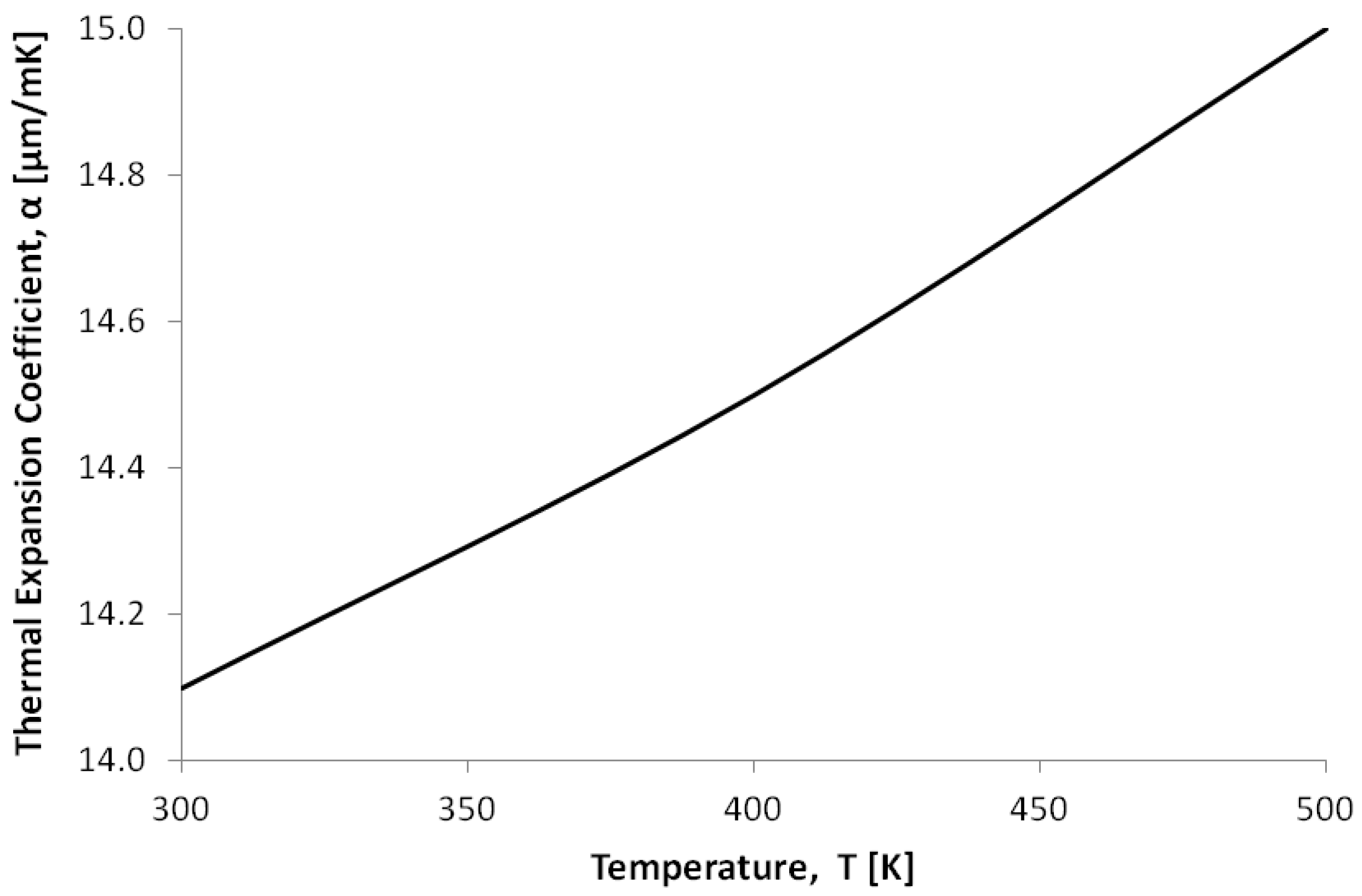
| Thermal expansion coefficient, [m/mK] | 2.80 | 2.80 | Refer to Figure 5 | 2.50 | Refer to Figure 5 |
| Specific heat capacity, c [J/kgK] | 712 | 712 | 128.7 | 712 | 128.7 |
| Thermal conductivity, k [W/mK] | 32 | 32 | 297 | 148 | 297 |
| Electrical resistivity [m] | 20 | 30 | 3.12 × 10 | 500 | 2.86 × 10 |
© 2018 by the authors. Licensee MDPI, Basel, Switzerland. This article is an open access article distributed under the terms and conditions of the Creative Commons Attribution (CC BY) license (http://creativecommons.org/licenses/by/4.0/).
Share and Cite
Cauchi, M.; Grech, I.; Mallia, B.; Mollicone, P.; Sammut, N. The Effects of Structure Thickness, Air Gap Thickness and Silicon Type on the Performance of a Horizontal Electrothermal MEMS Microgripper. Actuators 2018, 7, 38. https://doi.org/10.3390/act7030038
Cauchi M, Grech I, Mallia B, Mollicone P, Sammut N. The Effects of Structure Thickness, Air Gap Thickness and Silicon Type on the Performance of a Horizontal Electrothermal MEMS Microgripper. Actuators. 2018; 7(3):38. https://doi.org/10.3390/act7030038
Chicago/Turabian StyleCauchi, Marija, Ivan Grech, Bertram Mallia, Pierluigi Mollicone, and Nicholas Sammut. 2018. "The Effects of Structure Thickness, Air Gap Thickness and Silicon Type on the Performance of a Horizontal Electrothermal MEMS Microgripper" Actuators 7, no. 3: 38. https://doi.org/10.3390/act7030038