Dielectric Elastomer Actuators with Carbon Nanotube Electrodes Painted with a Soft Brush


Abstract
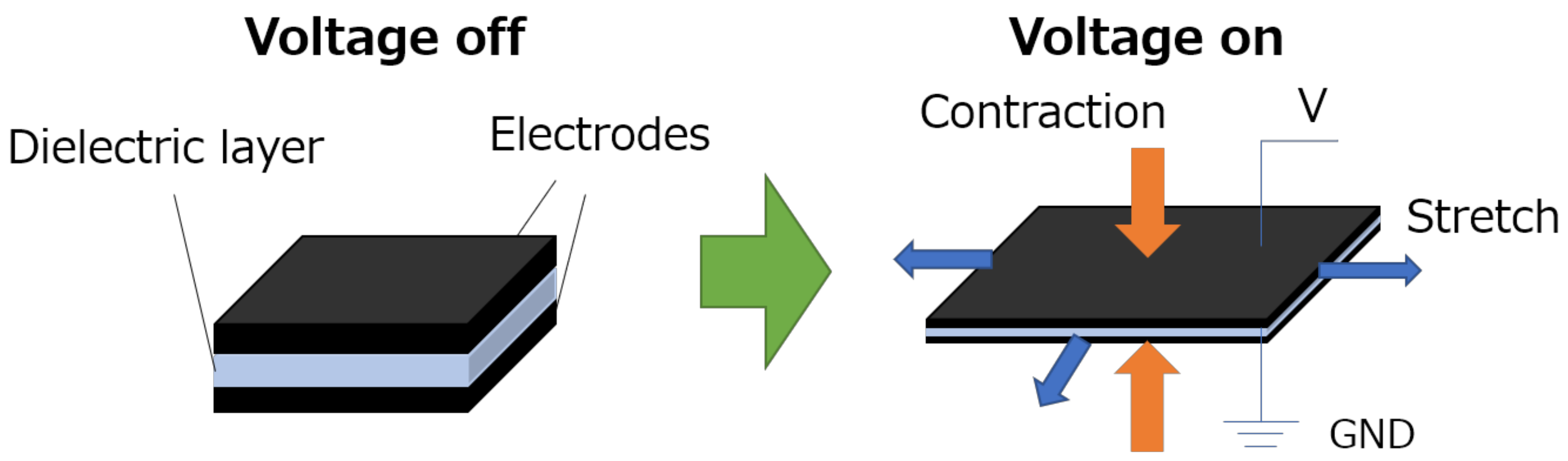
:1. Introduction
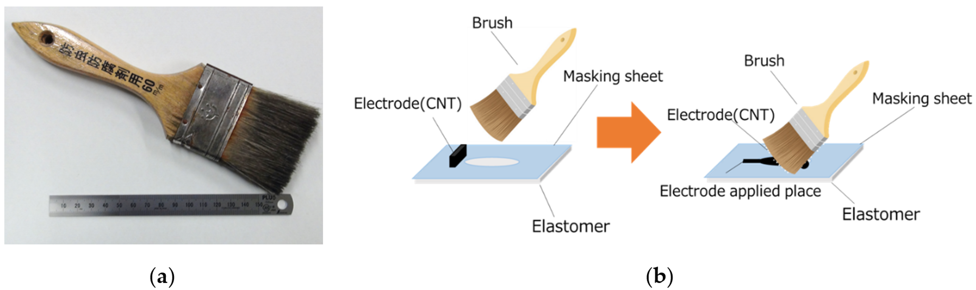
2. Materials and Methods
2.1. Observation Experiment
2.2. Performance Experiment
3. Results and Discussions
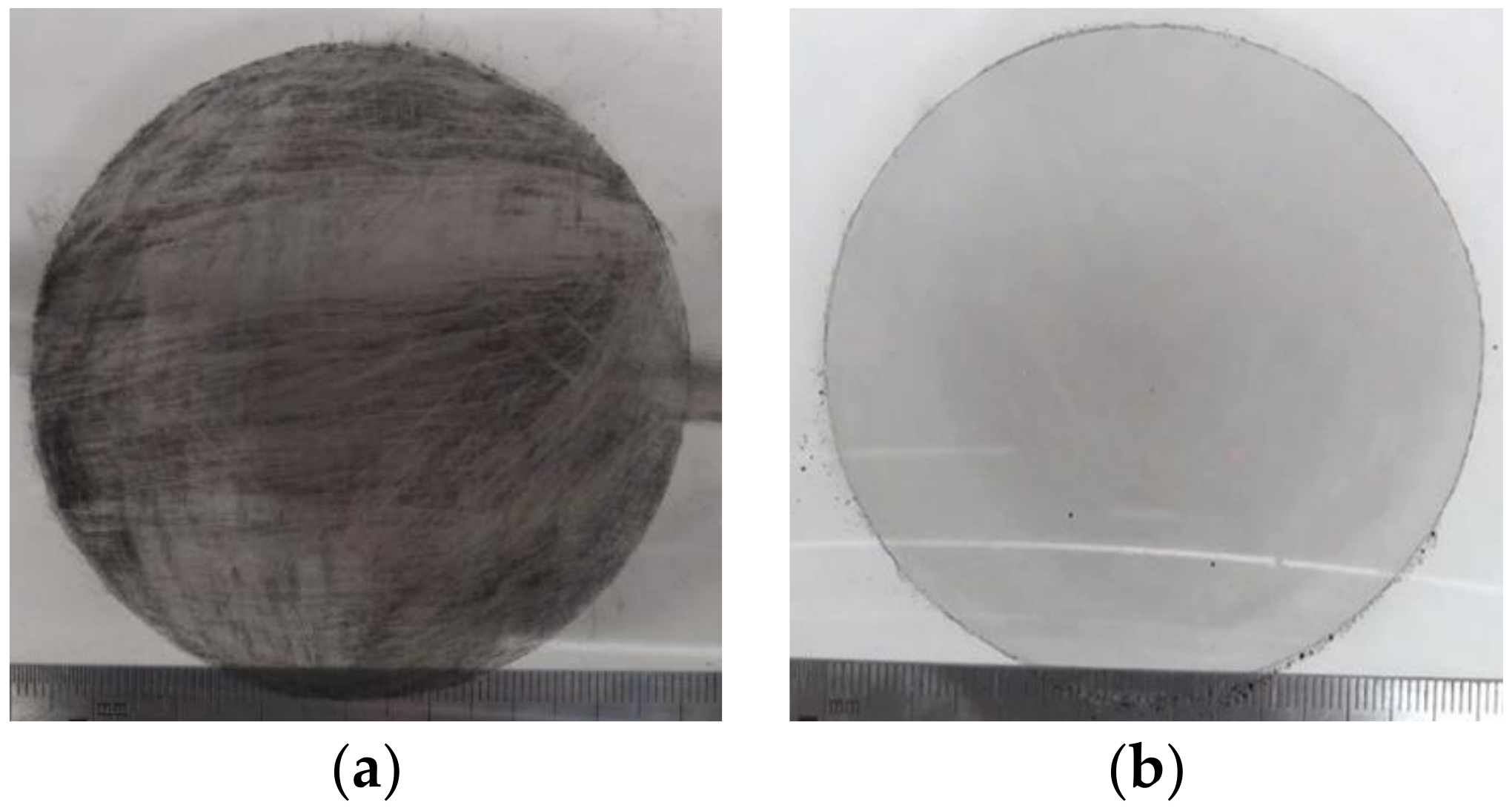
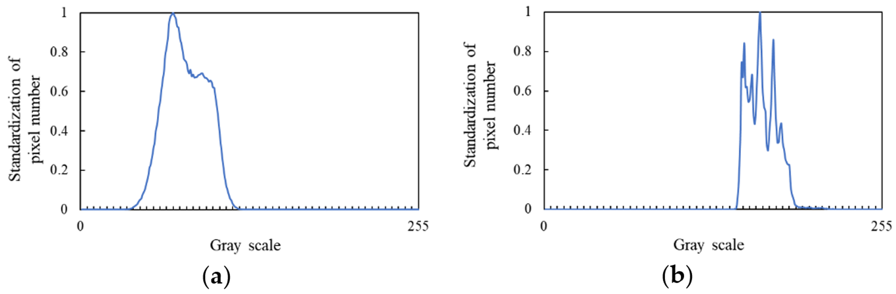
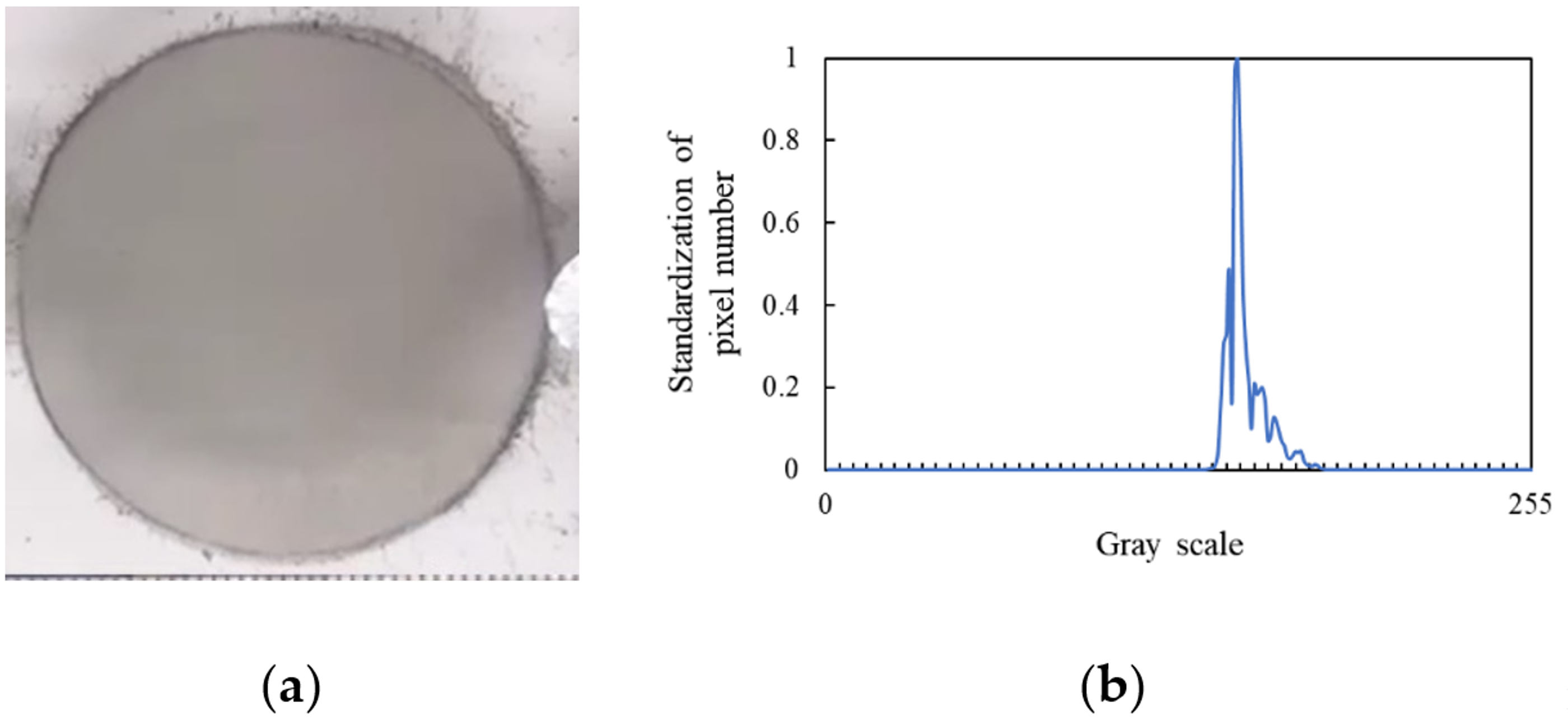
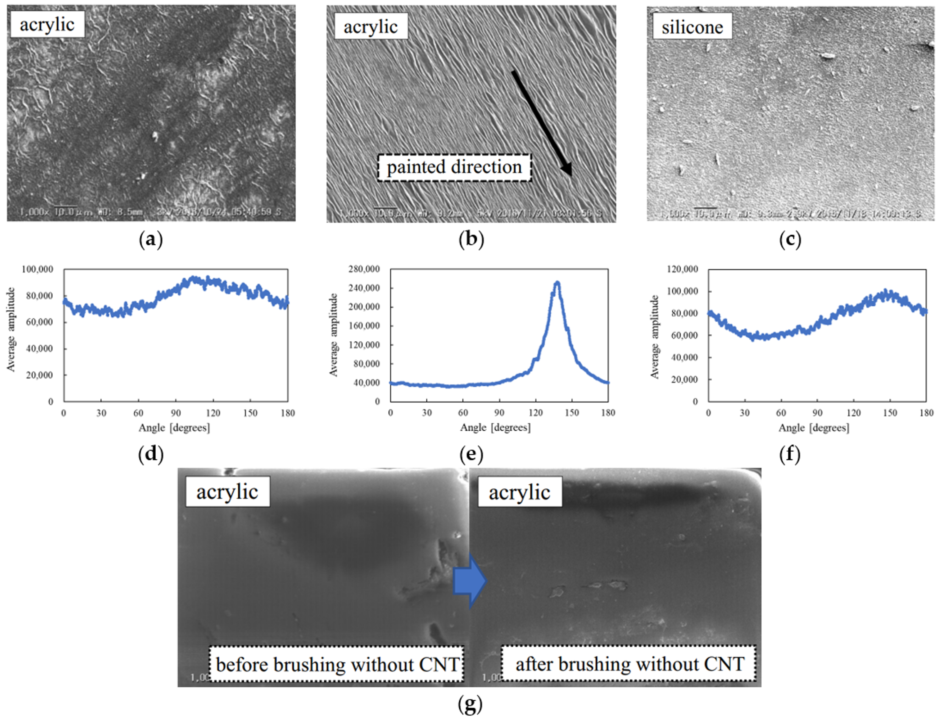
3.1. Observation Experiment
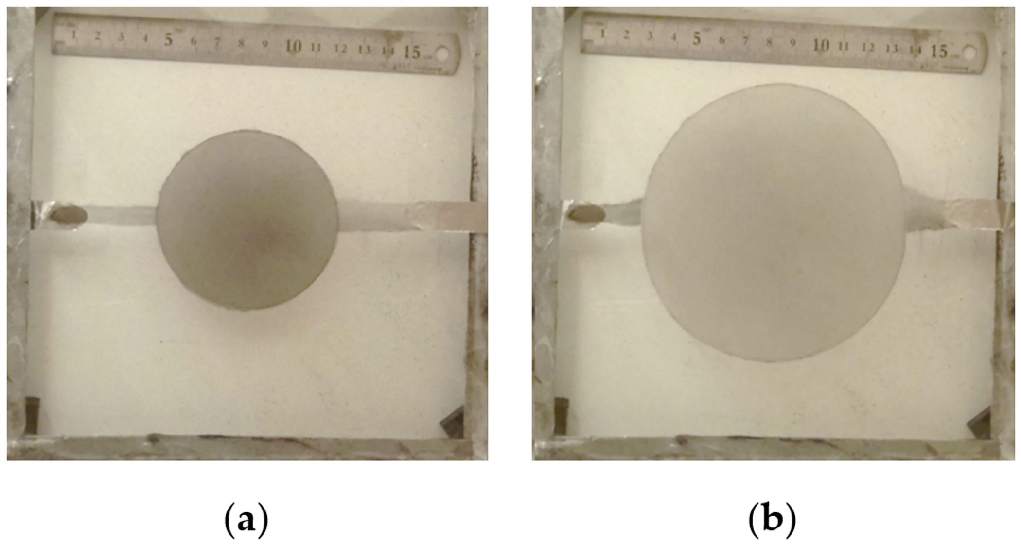
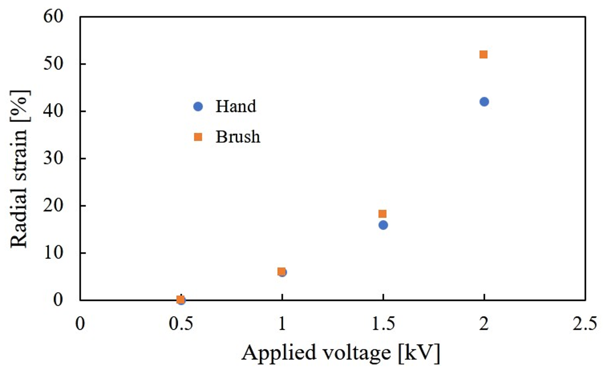
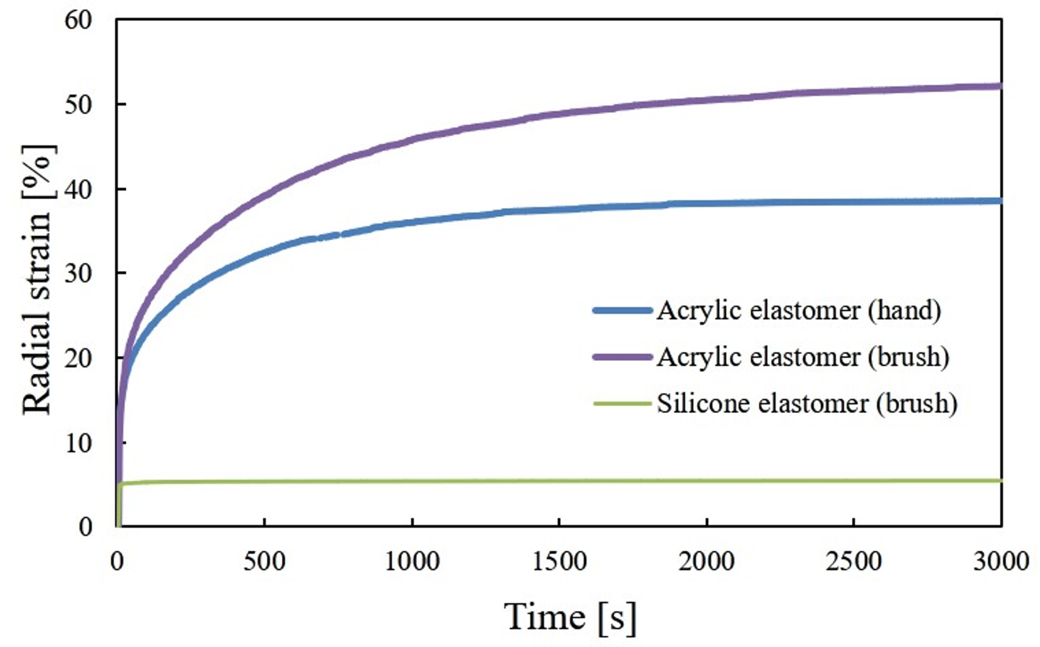
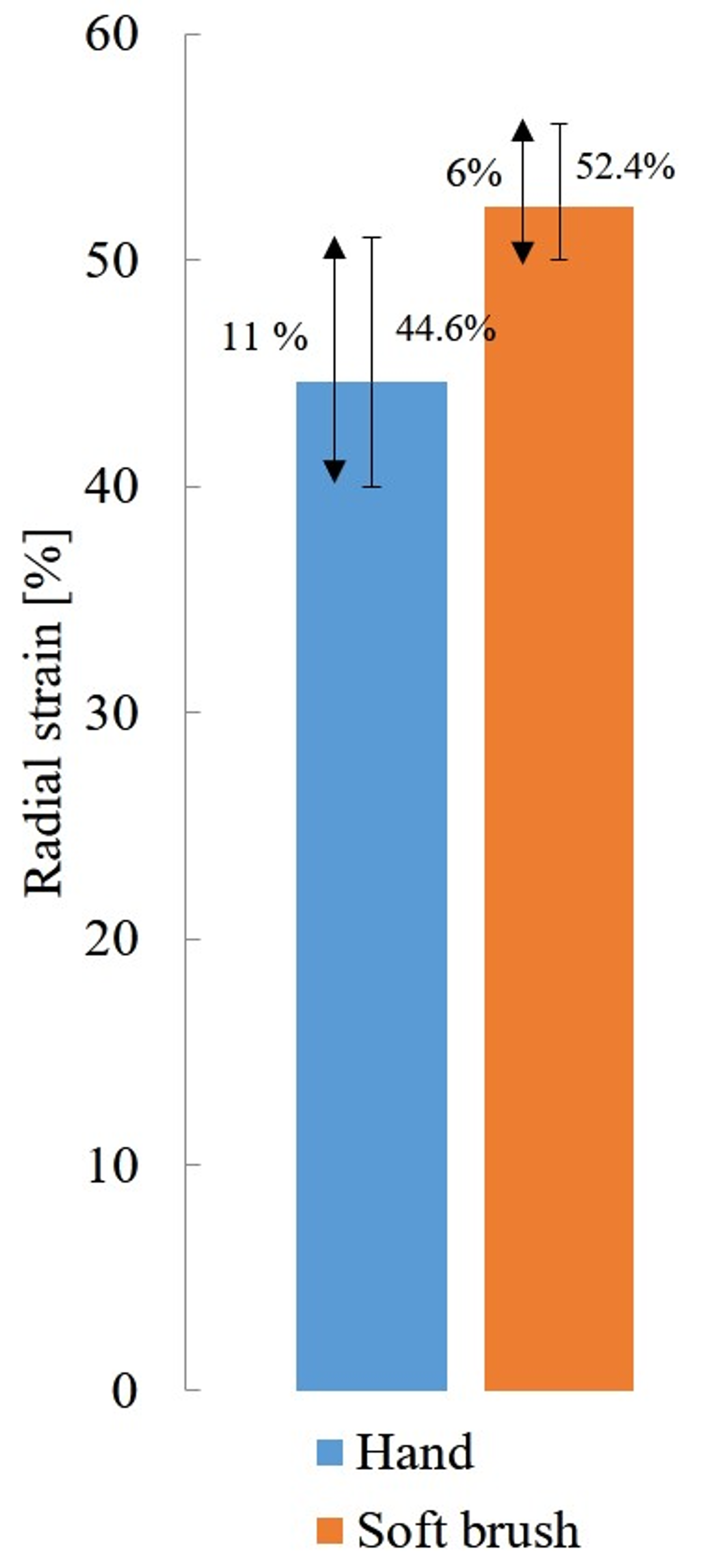
3.2. Performance Experiment
4. Conclusions
Author Contributions
Funding
Conflicts of Interest
References
- Suzumori, K.; Iikura, S.; Tanaka, H. Applying a flexible microactuator to robotic mechanisms. IEEE Cont. Syst. 1992, 12, 21–27. [Google Scholar]
- Laschi, C.; Cianchetti, M.; Mazzolai, B.; Margheri, L.; Follador, M.; Dario, P. Soft robot arm inspired by the octopus. Adv. Robot. 2012, 26, 709–727. [Google Scholar] [CrossRef]
- Cacucciolo, V.; Renda, F.; Poccia, E.; Laschi, C.; Cianchetti, M. Modelling the nonlinear response of fibre-reinforced bending fluidic actuators. Smart Mater. Struct. 2016, 25, 105020. [Google Scholar] [CrossRef] [Green Version]
- Tolley, M.T.; Shepherd, R.F.; Mosadegh, B.; Galloway, K.C.; Wehner, M.; Karpelson, M.; Wood, R.J.; Whitesides, G.M. A resilient, untethered soft robot. Soft Robot. 2014, 1, 213–223. [Google Scholar] [CrossRef]
- Pelrine, R.; Kornbluh, R.; Pei, Q.; Joseph, J. High-speed electrically actuated elastomers with strain greater than 100%. Science 2000, 287, 836–839. [Google Scholar] [CrossRef] [PubMed]
- Carpi, F.; De Rossi, D.; Kornbluh, R.; Pelrine, R.E.; Sommer-Larsen, P. Dielectric Elastomers As Electromechanical Transducers: Fundamentals, Materials, Devices, Models and Applications of an Emerging Electroactive Polymer Technology; Elsevier: Amsterdam, The Netherlands, 2008; ISBN 978-0-08-047488-5. [Google Scholar]
- Suo, Z. Theory of dielectric elastomers. Acta Mech. Solida Sin. 2010, 23, 549–578. [Google Scholar] [CrossRef]
- Poulin, A.; Rosset, S.; Shea, H.R. Printing low-voltage dielectric elastomer actuators. Appl. Phys. Lett. 2015, 107, 244104. [Google Scholar] [CrossRef] [Green Version]
- Maeda, S.; Hara, Y.; Sakai, T.; Yoshida, R.; Hashimoto, S. Self-walking gel. Adv. Mater. 2007, 19, 3480–3484. [Google Scholar] [CrossRef]
- Nakagawa, H.; Hara, Y.; Maeda, S.; Hashimoto, S. A pendulum-like motion of nanofiber gel actuator synchronized with external periodic pH oscillation. Polymers 2011, 3, 405–412. [Google Scholar] [CrossRef]
- DIELASTAR Research Project. Available online: https://www.festo.com/group/en/cms/10274.htm (accessed on 3 August 2018).
- Hosoya, N.; Baba, S.; Maeda, S. Hemispherical breathing mode speaker using a dielectric elastomer actuator. J. Acoust. Soc. Am. 2015, 138, 424–428. [Google Scholar] [CrossRef] [PubMed]
- Pelrine, R.; Kornbluh, R.; Joseph, J. Electrostriction of polymer dielectrics with compliant electrodes as a means of actuation. Sens. Actuators A Phys. 1998, 64, 77–85. [Google Scholar] [CrossRef]
- Keplinger, C.; Sun, J.Y.; Foo, C.C.; Rothemund, P.; Whitesides, G.M.; Suo, Z. Stretchable, transparent, ionic conductors. Science 2013, 341, 984–987. [Google Scholar] [CrossRef] [PubMed] [Green Version]
- Pelrine, R.; Kornbluh, R.; Joseph, J.; Heydt, R.; Pei, Q.; Chiba, S. High-field deformation of elastomeric dielectrics for actuators. Mater. Sci. Eng. C. 2000, 11, 89–100. [Google Scholar] [CrossRef]
- Lochmatter, P.; Kovacs, G. Design and characterization of an active hinge segment based on soft dielectric EAPs. Sens. Actuators A Phys. 2008, 141, 577–587. [Google Scholar] [CrossRef]
- Rosset, S.; Araromi, O.A.; Schlatter, S.; Shea, H.R. Fabrication process of silicone-based dielectric elastomer actuators. J. Vis. Exp. 2016, 108. [Google Scholar] [CrossRef] [PubMed]
- Bozlar, M.; Punckt, C.; Korkut, S.; Zhu, J.; Chiang Foo, C.; Suo, Z.; Aksay, I.A. Dielectric elastomer actuators with elastomeric electrodes. Appl. Phys. Lett. 2012, 101, 091907. [Google Scholar] [CrossRef]
- He, X.; Gao, W.; Xie, L.; Li, B.; Zhang, Q.; Lei, S.; Robinson, J.M.; Haroz, E.H.; Doorn, S.K.; Wang, W.; et al. Wafer-scale monodomain films of spontaneously aligned single-walled carbon nanotubes. Nat. Nanotech. 2016, 11, 633. [Google Scholar] [CrossRef] [PubMed]
- Cho, D.Y.; Eun, K.; Choa, S.H.; Kim, H.K. Highly flexible and stretchable carbon nanotube network electrodes prepared by simple brush painting for cost-effective flexible organic solar cells. Carbon 2014, 66, 530–538. [Google Scholar] [CrossRef]
- Ramasamy, E.; Lee, W.J.; Lee, D.Y.; Song, J.S. Spray coated multi-wall carbon nanotube counter electrode for tri-iodide (I3-) reduction in dye-sensitized solar cells. Electrochem. Commun. 2008, 10, 1087–1089. [Google Scholar] [CrossRef]
- Nobusa, Y.; Yomogida, Y.; Matsuzaki, S.; Yanagi, K.; Kataura, H.; Takenobu, T. Inkjet printing of single-walled carbon nanotube thin-film transistors patterned by surface modification. Appl. Phys. Lett. 2011, 99, 183106. [Google Scholar] [CrossRef]
- Shigemune, H.; Maeda, S.; Hara, Y.; Hosoya, N.; Hashimoto, S. Origami robot: A self-folding paper robot with an electrothermal actuator created by printing. IEEE/ASME Trans. Mechatron. 2016, 21, 2746–2754. [Google Scholar] [CrossRef]
- Shigemune, H.; Maeda, S.; Cacucciolo, V.; Iwata, Y.; Iwase, E.; Hashimoto, S.; Sugano, S. Printed paper robot driven by electrostatic actuator. IEEE Robot. Autom. Lett. 2017, 2, 1001–1007. [Google Scholar] [CrossRef]
- Ryokai, K.; Marti, S.; Ishii, H. I/O brush: Drawing with everyday objects as ink. In Proceedings of the SIGCHI Conference on Human Factors in Computing Systems, Vienna, Austria, 24–29 April 2004. [Google Scholar]
- Enomae, T.; Han, Y.; Isogai, A. Nondestructive determination of fiber orientation distribution of paper surface by image analysis. Nord. Pulp Pap. Res. J. 2006, 21, 253. [Google Scholar] [CrossRef]


| DEA A | DEA B | DEA C | |
|---|---|---|---|
| Material of elastomer | Acrylic | Acrylic | Silicone |
| Model number (Supplier) | VHB Y-4905J (3M) | VHB Y-4905J (3M) | ELASTOSIL FILM 2030 SHEET (WACKER) |
| Painting tool | Hand | Brush | Brush |
| DEA A | DEA B | DEA C | |
|---|---|---|---|
| Max value | 122 | 217 | 179 |
| Minimum value | 33 | 56 | 137 |
| Mean value | 78.5 | 164 | 151 |
| Standard deviation | 15.3 | 11.1 | 6.65 |
© 2018 by the authors. Licensee MDPI, Basel, Switzerland. This article is an open access article distributed under the terms and conditions of the Creative Commons Attribution (CC BY) license (http://creativecommons.org/licenses/by/4.0/).
Share and Cite
Shigemune, H.; Sugano, S.; Nishitani, J.; Yamauchi, M.; Hosoya, N.; Hashimoto, S.; Maeda, S. Dielectric Elastomer Actuators with Carbon Nanotube Electrodes Painted with a Soft Brush. Actuators 2018, 7, 51. https://doi.org/10.3390/act7030051
Shigemune H, Sugano S, Nishitani J, Yamauchi M, Hosoya N, Hashimoto S, Maeda S. Dielectric Elastomer Actuators with Carbon Nanotube Electrodes Painted with a Soft Brush. Actuators. 2018; 7(3):51. https://doi.org/10.3390/act7030051
Chicago/Turabian StyleShigemune, Hiroki, Shigeki Sugano, Jun Nishitani, Masayuki Yamauchi, Naoki Hosoya, Shuji Hashimoto, and Shingo Maeda. 2018. "Dielectric Elastomer Actuators with Carbon Nanotube Electrodes Painted with a Soft Brush" Actuators 7, no. 3: 51. https://doi.org/10.3390/act7030051