Simple Controller Design Based on Internal Model Control for Twisted and Coiled Polymer Actuator


Department of Robotics and Mechatronics, Tokyo Denki University, Tokyo 120-8551, Japan
*
Author to whom correspondence should be addressed.
Actuators 2018, 7(3), 33; https://doi.org/10.3390/act7030033
Submission received: 25 May 2018
/
Revised: 19 June 2018
/
Accepted: 21 June 2018
/
Published: 25 June 2018
(This article belongs to the Special Issue Electroactive Polymer Actuators for Soft Robotics)
Abstract
:A twisted and coiled polymer actuator (TCPA) is a novel soft actuator. TCPA is fabricated by twisting nylon fibers. The TCPA extends and contracts by heating and cooling. By applying conductive nylon fibers to the actuator, the electroactive TCPA can be driven by the Joule heating of the applied voltage. It has noteworthy properties such as a high power/mass ratio, large deformation, and low hysteresis. By applying conductive nylon fibers to the actuator, it can be driven by the electrical input. From these properties, many soft robots using the electroactive TCPA have been demonstrated, such as robotic hands, locomotion robots, robot skins, biomimetic robots, and so on. In this paper, to realize a simple controller design, an internal model control based on the identified model is applied. The applied controller can be designed easily without experience in parameter-tuning based on controls theory. The validity of the applied method is investigated through experiments.
1. Introduction
To realize the safe and smooth motion of robotics and nursing care application, a light and soft actuator is desired [1,2], which is often called a soft actuator. In particular, an electroactive polymer actuator made from polymeric materials and conductive materials is promising because of high power density and the possibility of miniaturization. Various types of the electroactive polymer actuators have been reported such as an ionic polymer metal composites actuator [3,4], a dielectric elastomer actuator [5], a conductive polymer actuator [6], a bucky-gel actuator [7,8], and so on.
In 2014, Haines et al. reported a soft actuator made from nylon fibers [9]. This actuator can be easily fabricated by twisting and coiling nylon fibers. From the fabrication method and structure of the actuator, this actuator is called as the twisted and coiled polymer actuator (TCPA) [10], the super-coiled polymer (SCP) actuator [11], or the twisted and coiled actuator (TCA) [12]. The actuation mechanism is based on a thermomechanical property that twisted and coiled nylon fibers contract and extend by heating and cooling. To make the actuation and control system simple, an electroactive TCPA is also reported by coating the TCPA with conductive materials or twining heating wires with the normal TCPA; thus, electric actuation by Joule heating can be realized easily [13]. Driving the actuator electrically, a driving system can be implemented simply. In addition, the actuator can be easily controlled by simple voltage or a current control method, similar to the control methods of DC motors.
TCPA has various notable properties. It is easily fabricated by commercially available nylon fibers such as nylon threads or fishing lines. Therefore, it is relatively low cost to fabricate the actuator. Compared with shape memory actuators, the TCPA has a low hysteresis property [9]. In addition, the TCPA realizes larger deformation over 20% and a high power/mass ratio. From these properties, many applications using the electroactive TCPA have been demonstrated, such as robotic human hands [11,12,14,15,16], power assist devices [17], wearable devices [18], deformation locomotion robots [19], flying robot [20], robot skin for human robots [21], and biomimetic robots [22].
Many types of control system design methods for the electroactive TCPA had been proposed. In many previous papers on the control system design, proportional-integral-differential (PID) control is applied for control of the displacement or output force. By tuning PID gains, the desired control performance is realized. Yip and Niemeyer proposed a linear time invariant (LTI) model of the actuator based on the physical phenomena and designed a proportional-differential (PD) controller [23]. Arakawa et al. modeled the thermomechanical and thermoelectric property as a linear time invariant black box model, and designed a PID controller based on the identified model [24,25]. Sutton et al. designed a simple force control system based on the LTI first order model [17]. Luong et al. applied an adaptive PID sliding mode control to achieve high tracking and robust performance [26]. We identified the model of the actuator by a grey-box modeling, and applied the PID control to the antagonistic-type TCPA [27], and applied the PI control with an anti-windup compensator to the single TCPA [28].
These research studies indicate that the PID control can realize high tracking and robust performance if the controller gains are tuned adequately. However, tuning of the appropriate PID gains is difficult. Although various auto-tuning methods were reported, such as the Ziegler–Nichols method, the Chien-Hrones-Reswick (CHR) method, and optimization based on an evaluation function [29], the PID gains to realize the desired response need to be determined by the trials and errors of preliminary experiments. From these problems, a more simple control method for stabilizing the control system of the TCPA and realizing the desired response is required.
In this paper, in order to solve these problems, a control system design method known as an internal model control is applied. This controller structure is simple, and can be designed easily without experience in parameter tuning based on controls theory. The internal model control consists of the feedforward controller and feedback controller based on the model. The control system can realize a high tracking performance, and the desired response of the TCPA is obtained due to a feedforward control signal and a feedback of estimated disturbances. In this paper, the control system performance is verified through experiments. The rest of the paper is organized as follows: a control system design method of the TCPA is shown in Section 2. Experiment verification of the proposed control system design is shown in Section 3. The conclusion of this paper is shown in Section 4.
2. Method
In this section, we explain control system design methods for the TCPA. To design the controller based on the model, a gray-box modeling is applied. In addition, the internal model control method is introduced.
2.1. Modeling
For control system design, a physical model of the actuator is derived, although the detailed physical model [30,31,32,33] and the detailed model based on experiment data [34,35] have been reported. However, these detailed models are unsuitable for control system design due to the complexity of the model structure and a number of parameters. In the case of using these detailed models, the LTI model for the control system design is computed by linearization methods. To derive the simple model for control system design, a grey-box modeling based on the LTI physical model is applied with reference to methods of Yip and Niemeyer [23].
In this paper, the electroactive TCPA is activated by Joule heating and controlled by the applied voltage. The response of the TCPA has a relationship to temperature variation. In the case of Joule heating, the temperature has a relationship to the applied electric power. Therefore, the model of TCPA is assumed to consist of nonlinear statics of Joule’s law and LTI dynamics from applied power to displacement. Here, the electric power is assumed to be proportional to the square of the applied voltage in the unchanged condition of electric resistance, which is the same as the reference of Yip et al. [23] and Arakawa et al. [24]. Here, as with reference of Yip and Niemeyer [23], the model of the TCPA is assumed to be expressed as a series connection of the thermomechanical model and the thermoelectric model:
where y(t) is a displacement, ΔT(t) is a temperature variation from an ambient temperature, v(t) is an input voltage, m, d, and k are mechanical parameters, i.e., mass, damping coefficient, and spring constant, Cv is a heat capacity, α is a heat transfer coefficient, Sc is an area of the surface of the TCPA, c is a proportional coefficient from a temperature variation to a generated force, and R is an electric resistance.
By combining Equations (1) and (2), the dynamical model of the TCPA from the input voltage v(t) to the displacement y(t) can be expressed as a third-order ordinary differential equation:
where a2 = (dCv + mαSc)/mCv, a1 = (kCv + dαSc)/mCv a0 = kαSc/mCv, and b0 = c/mRCv. The model parameters of Equation (3) are identified from the input–output data of the experiment results.
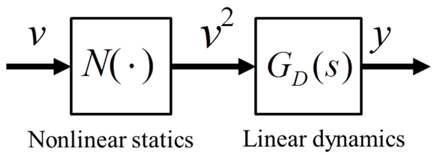
For control system design, Equation (3) is described as a system in Figure 1. The model of the TCPA consists of two sub-systems: nonlinear statics N and LTI dynamics GD, which are connected in series. N is expressed as a square function:
The transfer function of the linear dynamics GD(s) from the squared input voltage v2(t) to the displacement y(t) is expressed as a third-order transfer function;
In case of overheating, these model parameters might be varied in response to the input voltage, since the materials property of the TCPA depends on the temperature. Furthermore, in case of excessive contraction, these parameters might be varied due to the coil–coil contact. These factors should be considered for the wide range activation [31,33]; however, our modeling method is effective for normal use of the feedback control, since the simple controller design and adequate control performance can be realized, as described later.
2.2. Controller Design
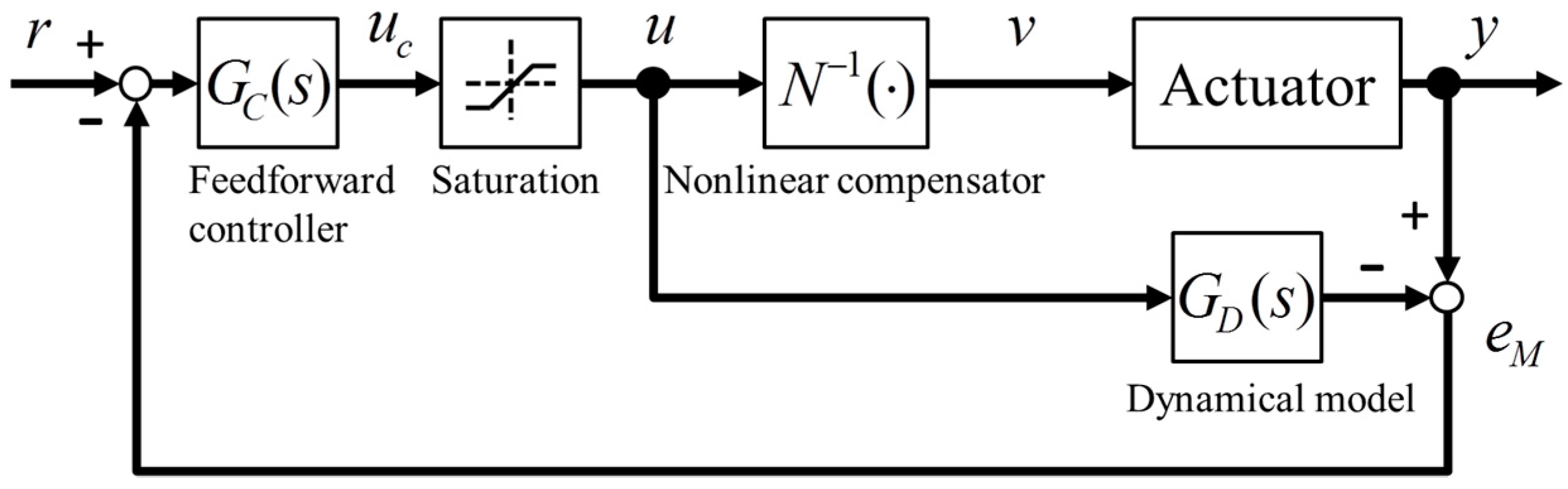
In this section, a controller design method is explained. The block diagram of the control system is shown in Figure 2. The control system consists of an inverse compensator of static nonlinearity N−1, a feedforward controller GC, and a nominal model GD.
First, the inverse compensator N−1 for canceling the nonlinearity of Joule’s law is implemented by the square root function:
where u(t) is the control signal calculated by the controller, and v(t) is the input voltage. By inserting the series compensation of Equation (6) after the controller GC, the control system can be designed by linear control theory.
To avoid breaking the actuator by overheating, the maximum input voltage is limited to within riskless driving voltage. The maximum input voltage is set so that the actuator isn’t overheated nor does it reach the displacement limitations of the coil–coil contact. In addition, the minimum input voltage also is limited, since the negative control signal is unrealized in normal voltage driving. Therefore, the saturated control signal u(t) is given as:
where umax and umin are the limits of the square value of input voltage and uc is the control signal of the controller GC. Note that the saturation umax is determined by the preliminary experiment, and umin is set to zero.
The internal model control based on the LTI dynamical model is designed to be the same with the reference of Morari and Zafirou [36]. The arbitrary reference model can be applied under the conditions of a minimum phase system. In this paper, for simplification of the controller design, the reference model F(s) is given as a conventional low-pass filter:
where λ is a time constant. Here, the time constant λ is adjusted so that the controller can realize the desired response from the reference signal to the output. Note that the reference model is expressed as the third-order transfer function so that the controller GD(s) becomes proper.
Next, to cancel the linear dynamics GD(s), the controller GC(s) from the reference signal to the control signal is given as the inverse model of linear dynamics:
Note that GD(s) is assumed to have stable poles and zeros. If the modeling error and any disturbance do not exist, the response from the reference signal to the output becomes the desired response based on the reference F(s), since the controller GC(s) balances the poles and zeros of the linear dynamics. However, the output is not able to track under the conditions with the unconsidered factors such as nonlinear property, disturbances, and nominal error in actual environments. Therefore, a mechanism for considering these factors is needed.
The feedback mechanism compensating the influence of the modeling error and some disturbance is designed. Here, the deviation eM between the actuator output and the estimated output of the model is expressed as:
To compensate eM, the control signal uc is given as:
where r is a reference signal. By applying the above control method, the response from the reference signal to the output is equal to the desired response of the reference model F(s), since the eM is eliminated due to the feedback compensation.
The internal model control has the following advantages:
- It is extremely simple to design the control system, since the control system can be implemented by only adjusting the reference model if the model of the TCPA can be derived.
- This control method can realize a good control performance that is close to the desired feedforward control where the modeling error and some disturbance don’t exist.
- The internal stability of the control system is guaranteed, since the LTI physical model of the TCPA doesn’t have the unstable zeros and poles.
3. Experiment
The validity of the control system is investigated through experiments. In this section, we explain the experimental environment, the system identification results, and the experiment results.
3.1. Experimental Environment
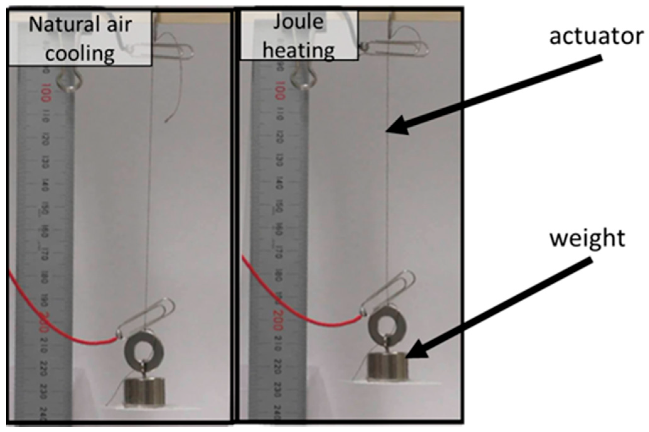
The electroactive TCPA used in the experiments was fabricated by the silver-plated nylon thread (AGposs 100/2, Mitsufuji, Kyoto, Japan). The fabrication method is the same as our previous paper [28]. The nylon thread in an uncoiled state is 300 mm in length and 0.1 mm in diameter. The nylon thread in a coiled state is 85 mm in length and 0.4 mm in diameter after overtwisting. The configuration of the actuator is 100 mm in length and 0.3 mm in diameter. The electric resistance is 74.2 Ω in an unloaded condition. The behavior of electric activation of the electroactive TCPA is shown in Figure 3. The length of the actuator is 100 mm. When a 20-g weight is attached to the end of the actuator, the maximum strain of the actuator is about 10% by 10 V.
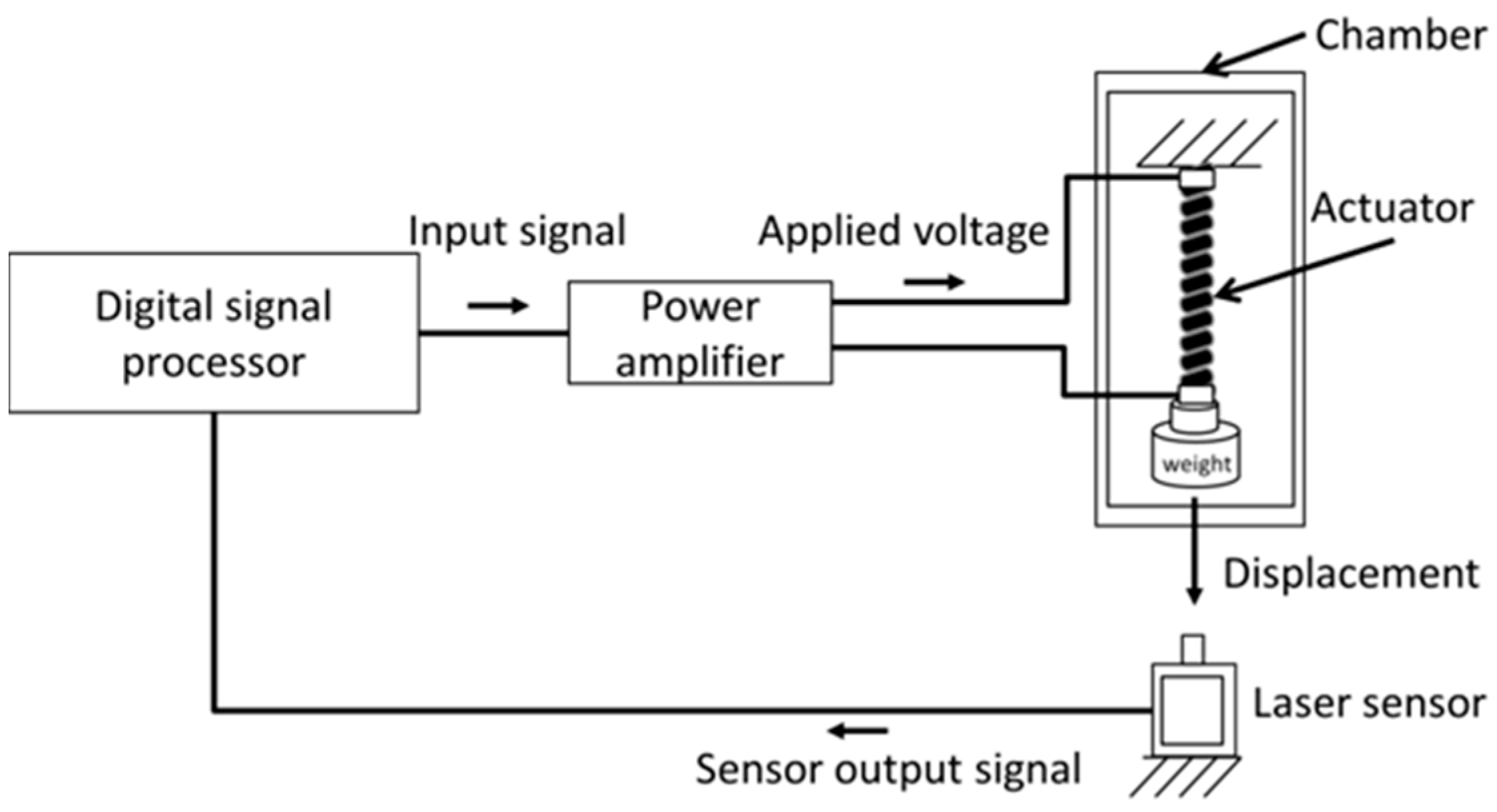
A schematic diagram of our experimental environment is shown in Figure 4. In the environment, a real-time measurement and control system is implemented by using a digital signal processor system (MTT, Tokyo, Japan, SBOX2). A control program is built in MATLAB/Simulink and loaded to the digital signal processor system. The control input signal is computed in a digital signal processor and applied to the power amplifier. The power amplifier outputs the driving voltage according to the control signal. The output displacement of the actuator is measured by a laser displacement meter (KEYENCE, Osaka, Japan, IA-100), and the displacement data is input to the digital signal processor. The displacement is defined as the shrinkage ratio [%] of the initial length of the actuator. The sample time of the controller is set as 1 ms. The actuator is placed in a chamber (As-one). In the experimental environment, the temperature in the chamber is set as 23 °C, and a weight of 20 g is attached to the actuator.
3.2. Model Identification
In this section, we explain the identification method of the dynamical model. The model parameters were derived using the input–output data of the experiments. In the experiment, the input voltage–output displacement of pulse response with multilevel amplitudes was measured. For parameter identification, a discrete-time state space model of the actuator is identified by using the N4SID function of MATLAB. The parameter of the transfer function GD(s) is derived by using the discrete-continuous conversion method with zero-order hold.
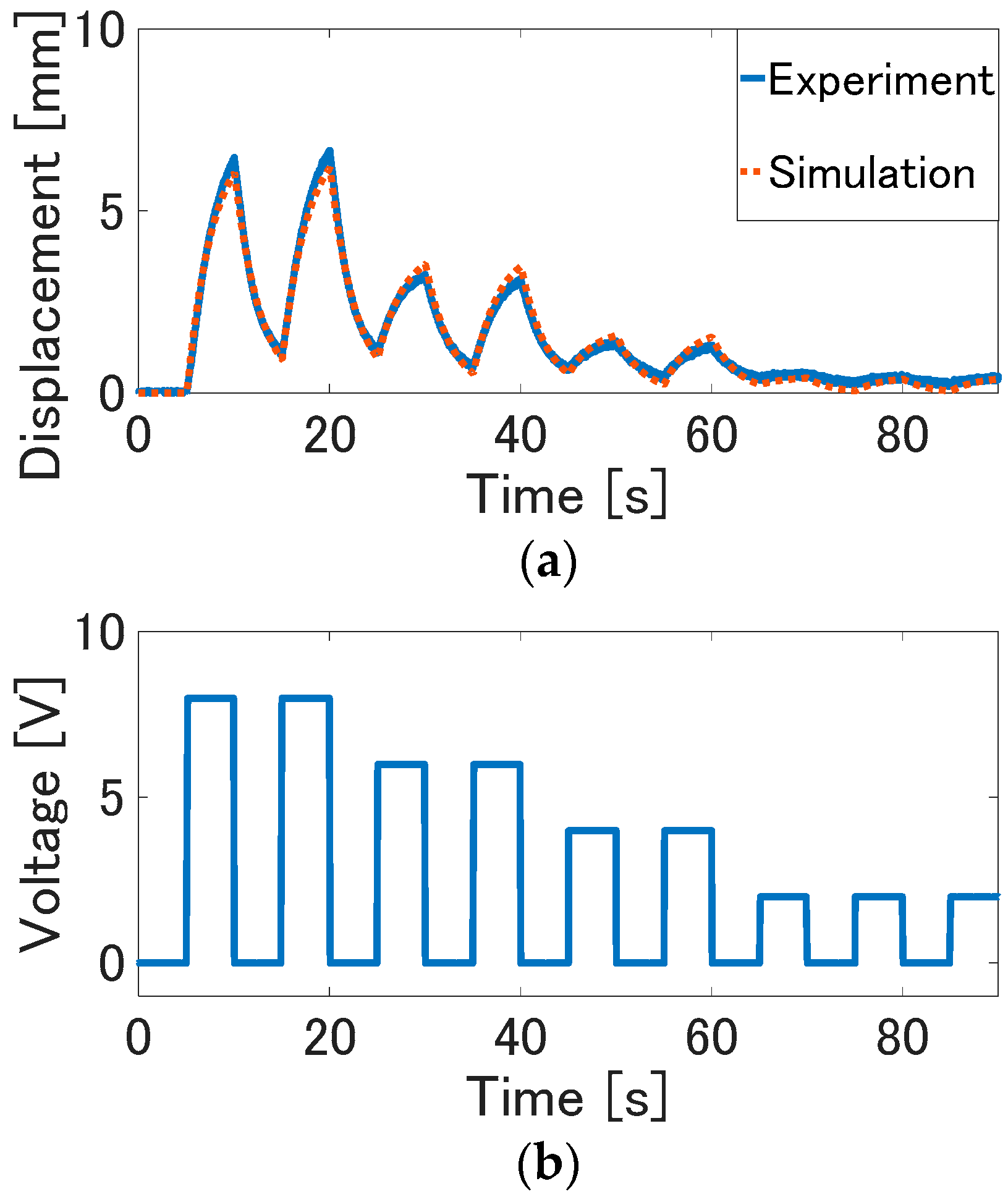
By using a system identification toolbox of MATLAB, the model parameters are identified as a2 = 371.1, a1 = 1003, a0 = 44.09, and b0 = 42.09. The identification results are shown in Figure 5. In this figure, the experimental data and simulation result of the identified model are plotted. To evaluate the precision of the identified physical model, a fitting ratio [%], which is an index of precision of the identified model, is calculated as:
where ysim(i) and y(i) are the output data of simulated model, the experimental output data is at time i, Tsim is the simulation time, and ya is the average of the output data. The fitting ratio calculated by Equation (12) is 89.25%. The simulation results agree well with the experimental result.
3.3. Experimental Result
In this experiment, the validity of the internal model control is investigated, as the controller can balance the actuator properties adequately, and realizes the desired response.
3.3.1. Experimental Results with Sinusoidal Reference Signals
The reference signals are set as sinusoidal waves with a frequency of 0.1 Hz and 0.025 Hz, and a peak value from 2 mm to 6 mm. The reference signal is set as the composite wave with the sinusoidal waves of 0.1 Hz and 0.025 Hz. The time constant λ is set to 0.5 s, as the control signal is not saturated. To verify the validity of the proposed control system, the experiment result of the internal model control is compared to the conventional feedforward control based on the LTI model. In the conventional feedforward control, the control signals uc is given as uc = Gc(s)r(s) [24,27].
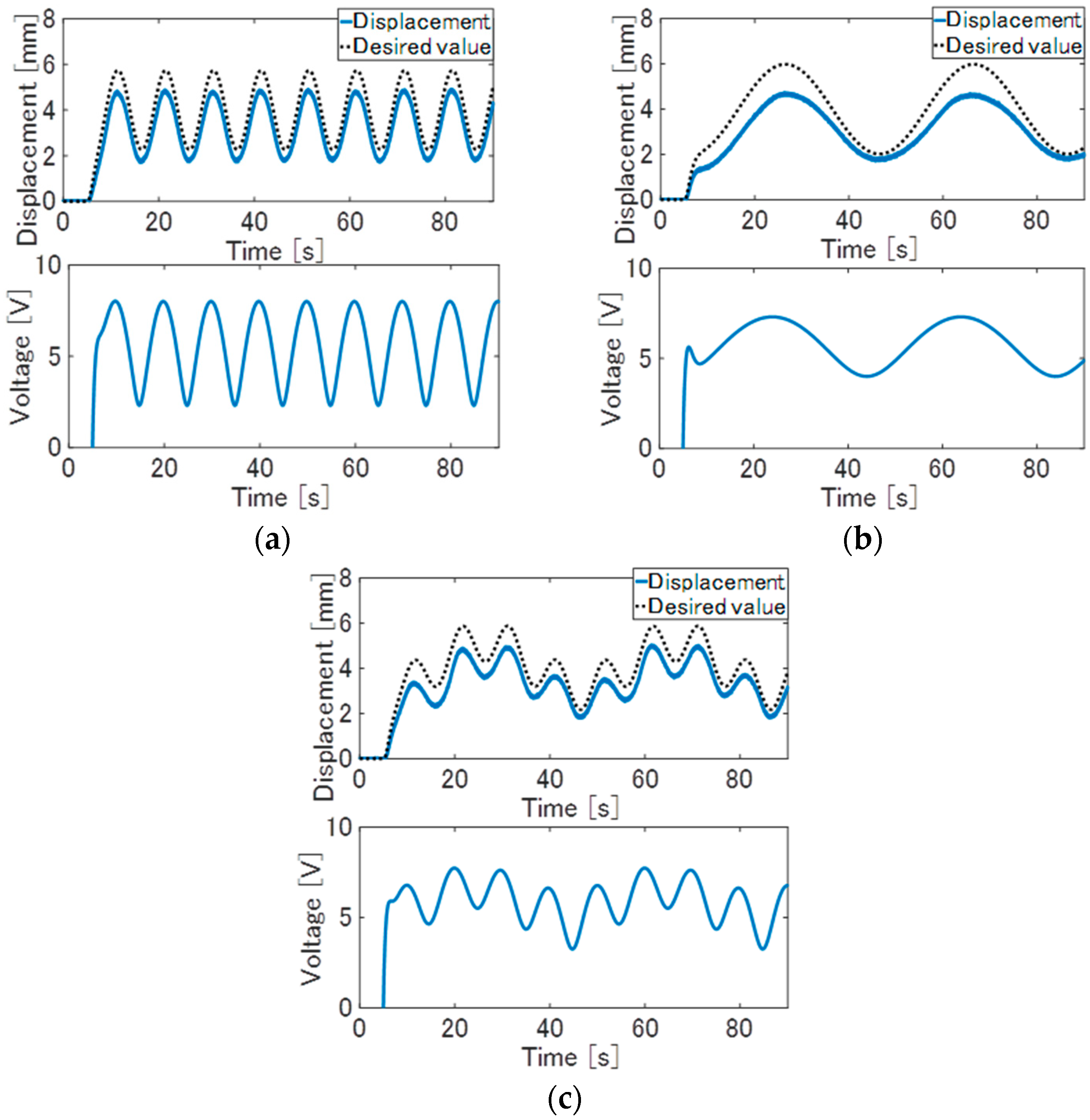
Experiment results of the feedforward control are shown in Figure 6. In this figure, the solid line is the displacement of the TCPA, and the dotted line is a desired value, that is, the reference signal after passing through the reference model F(s). From Figure 6a,b, although the displacement is varied along the reference signal, the large tracking error between the displacement and the desired value arises. From Figure 6c, the large tracking error that arises is the same as with the result of the sinusoidal wave of 0.1 Hz and 0.025 Hz. This tracking error is considered to arise due to the unconsidered factors such as nonlinear thermal conductivity [31], mechanical property [35], noise, the parameter variation due to the temperature dependence and the coil–coil contact, and so on. Furthermore, these parameters might be varied due to the coil–coil contact, and so on. Therefore, with the reference of Yip and Niemeyer [23], Arakawa et al. [24], and Suzuki and Kamamichi [27], the feedforward control based on the LTI model cannot realize the desired response.
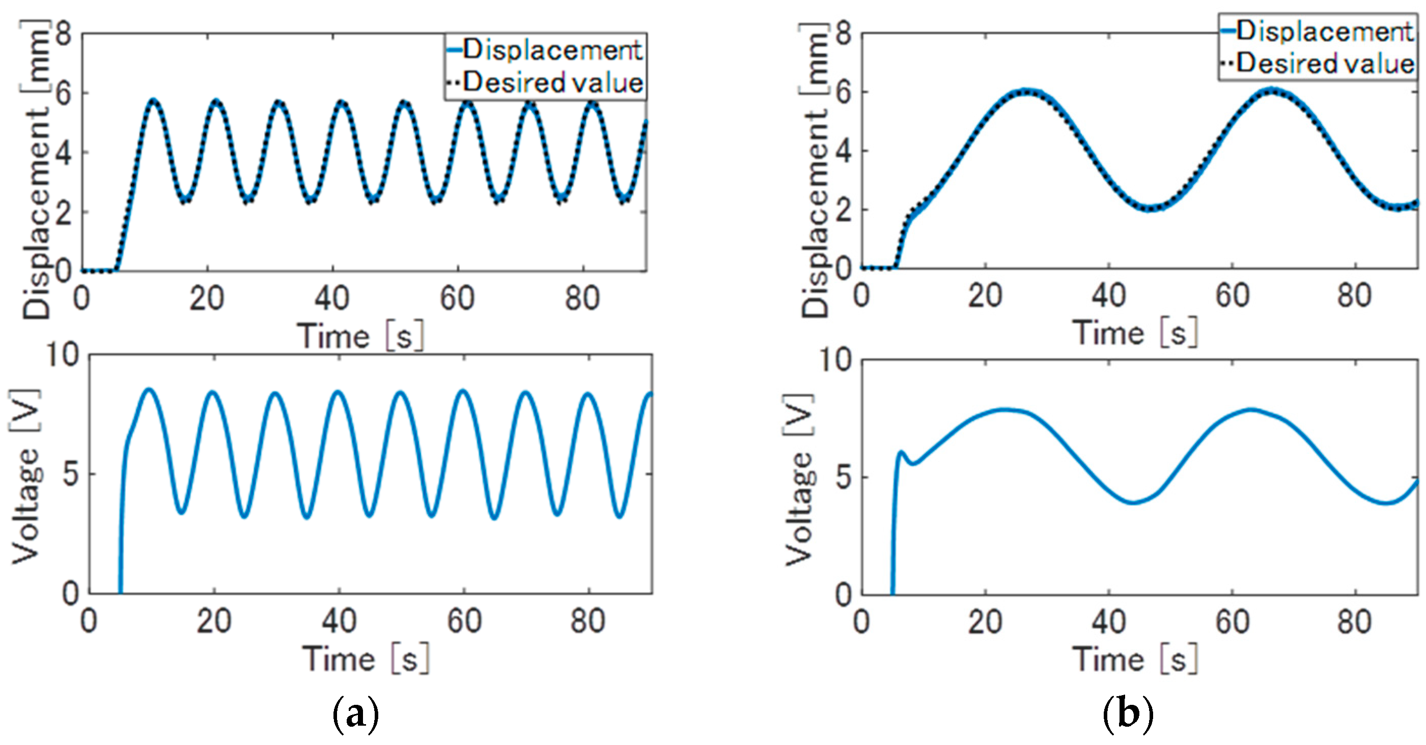
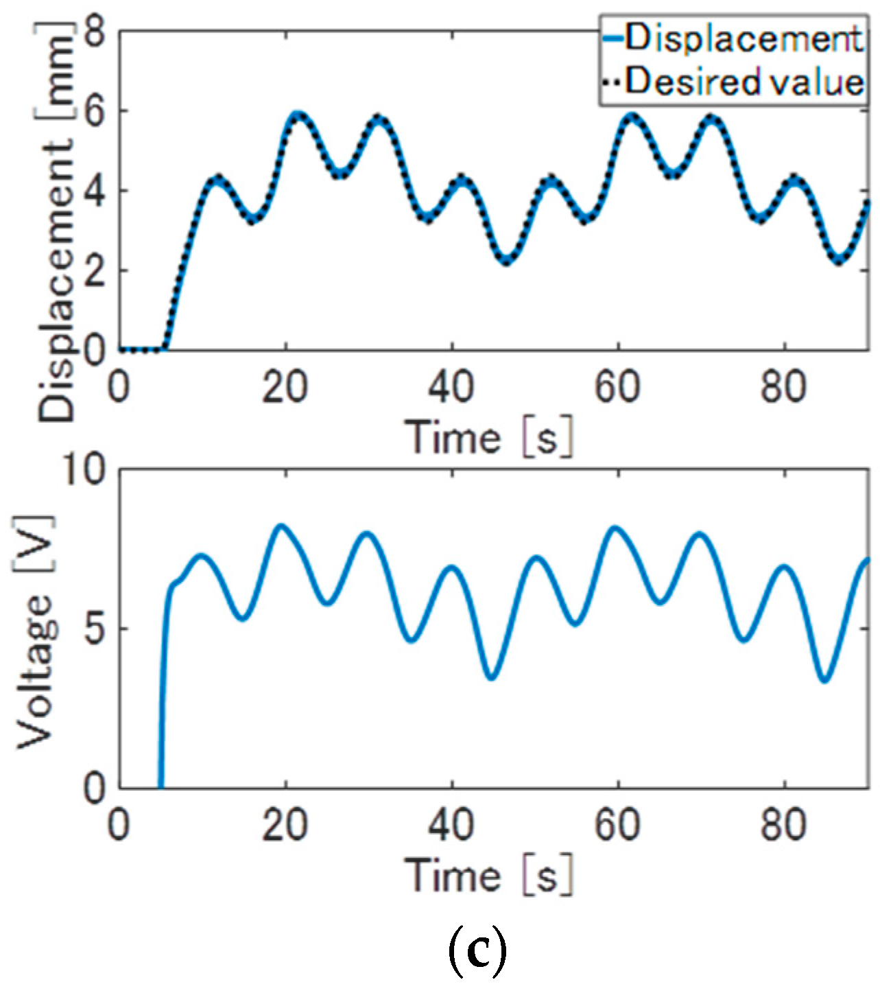
The experimental results of the internal model control are shown in Figure 7. In each of the control results, the large error decreased, and the displacement of the actuator can be tracked to the desired value compared to the feedforward control. As observed in the results, the desired control performance can be realized due to the feedback of deviation between the actual output and the estimated output of the nominal model. In the experiment, the displacement control can be realized in the same response performance for the other amplitude and frequency of the target signal if the input voltages are within the upper limitation of the input saturation. Therefore, as shown in the results, the internal model control can eliminate the nominal error and disturbance, and also realize the desired control performance.
3.3.2. Experimental Results with Step Reference Signals
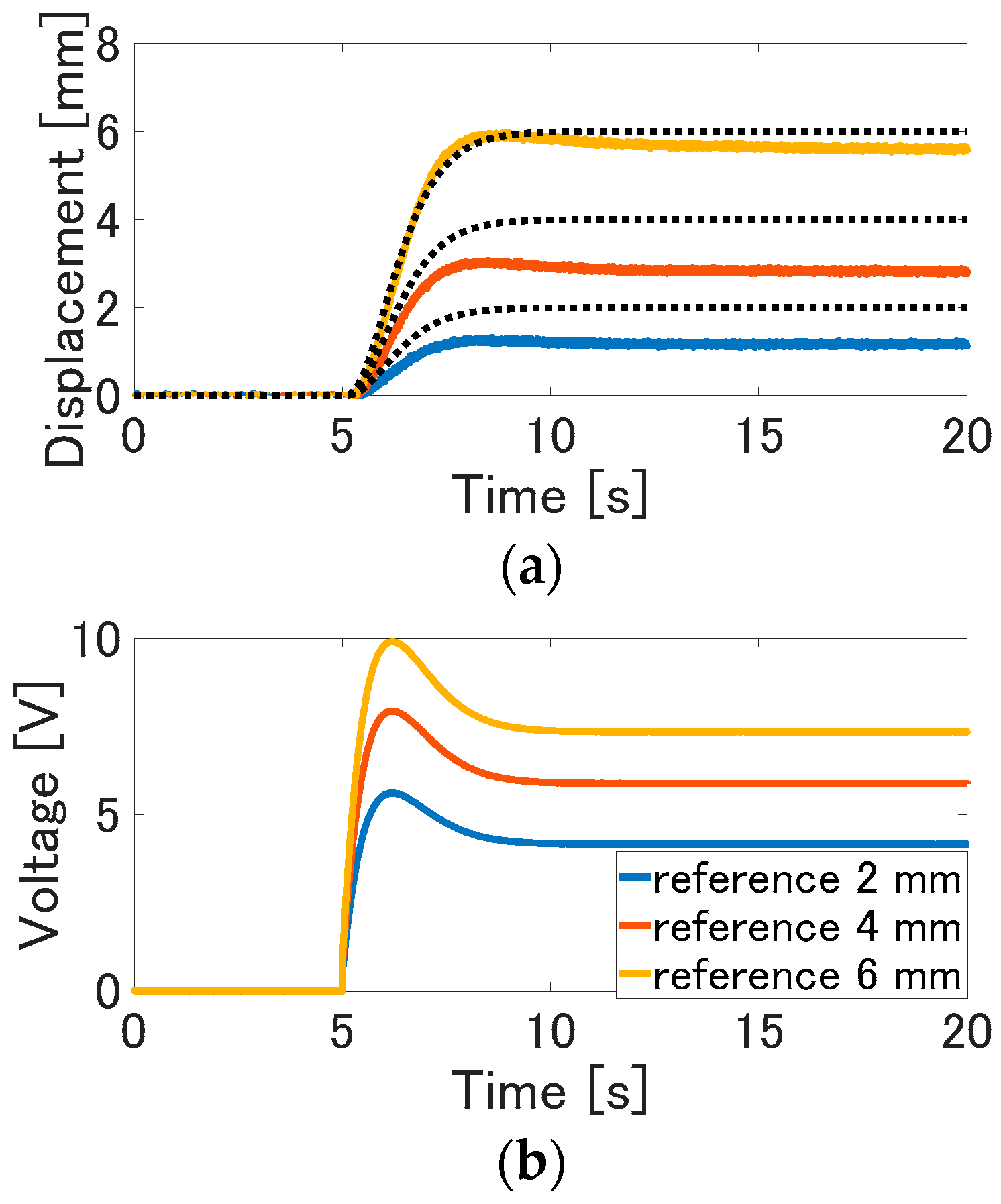
To further investigate the control performance of the internal model control, the reference signals are set as the step wave with multilevel amplitude. The experimental results of the conventional feedforward control are shown in Figure 8. In each experimental result of the step wave, the large steady state error between the displacement and the desired value arises. This steady state error is considered due to the modeling error and disturbances. This tracking error is considered to arise due to the unconsidered factors such as nominal errors and disturbance. Therefore, the feedforward control based on the LTI model cannot realize the desired response.
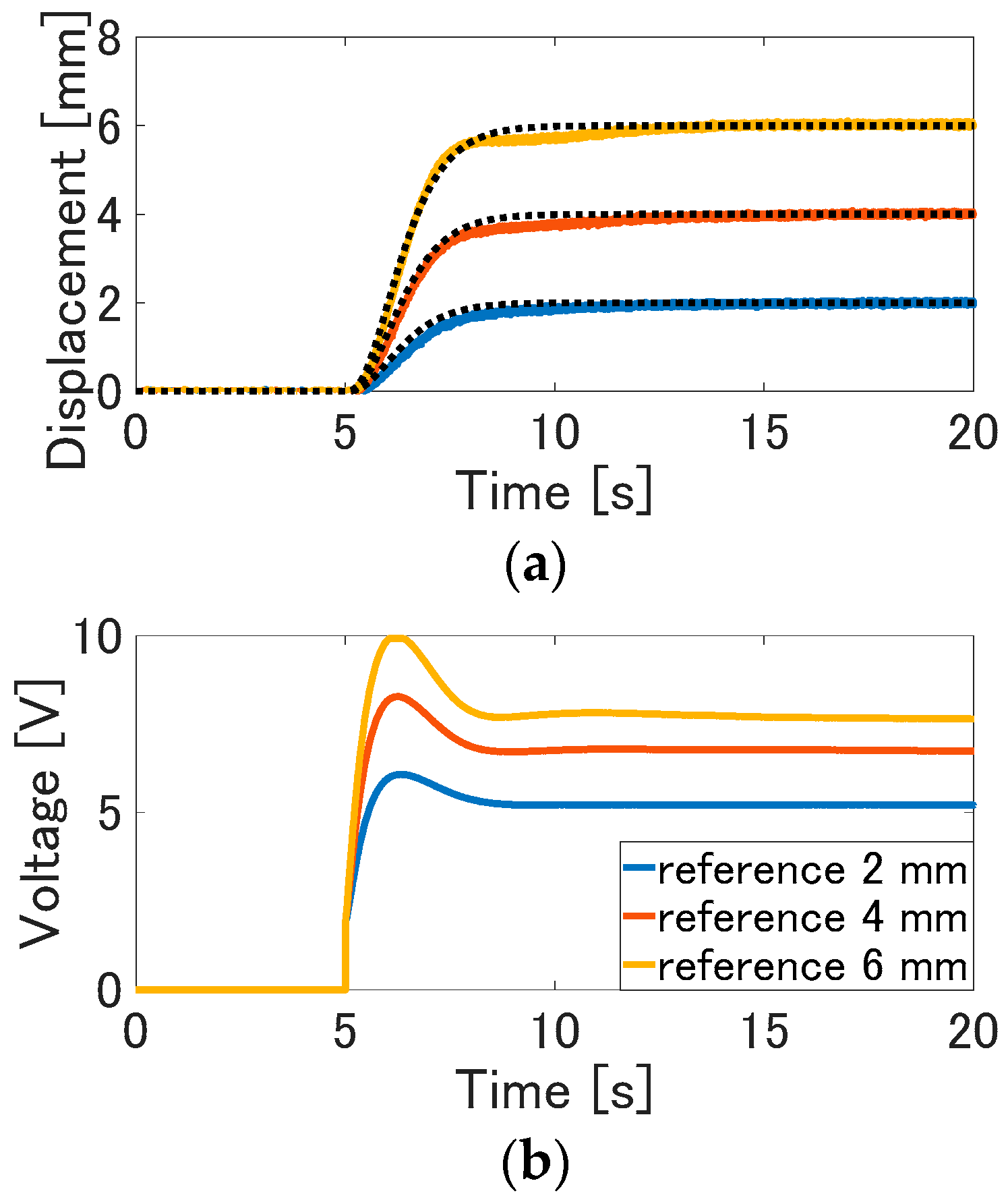
The experimental results of the internal model control are shown in Figure 9. In each experimental result, the overshoot doesn’t arise, and the displacement can be tracked to the desired value. Although quite small errors between the displacement and the desired value arise in the transient response, the steady state errors are eliminated due to the feedback of the internal model. The displacement is able to be tracked to the desired value, since the control signal is adequately adjusted due to the feedback of the output error. From these results, the nominal error and disturbances can be eliminated due to the internal model feedback. As also shown in these results, the internal model control can balance the actuator properties adequately and realize the desired control performance.
3.3.3. Experiment of the Pole Assignment
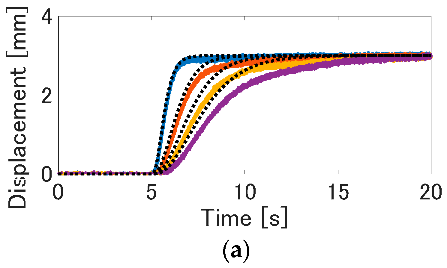
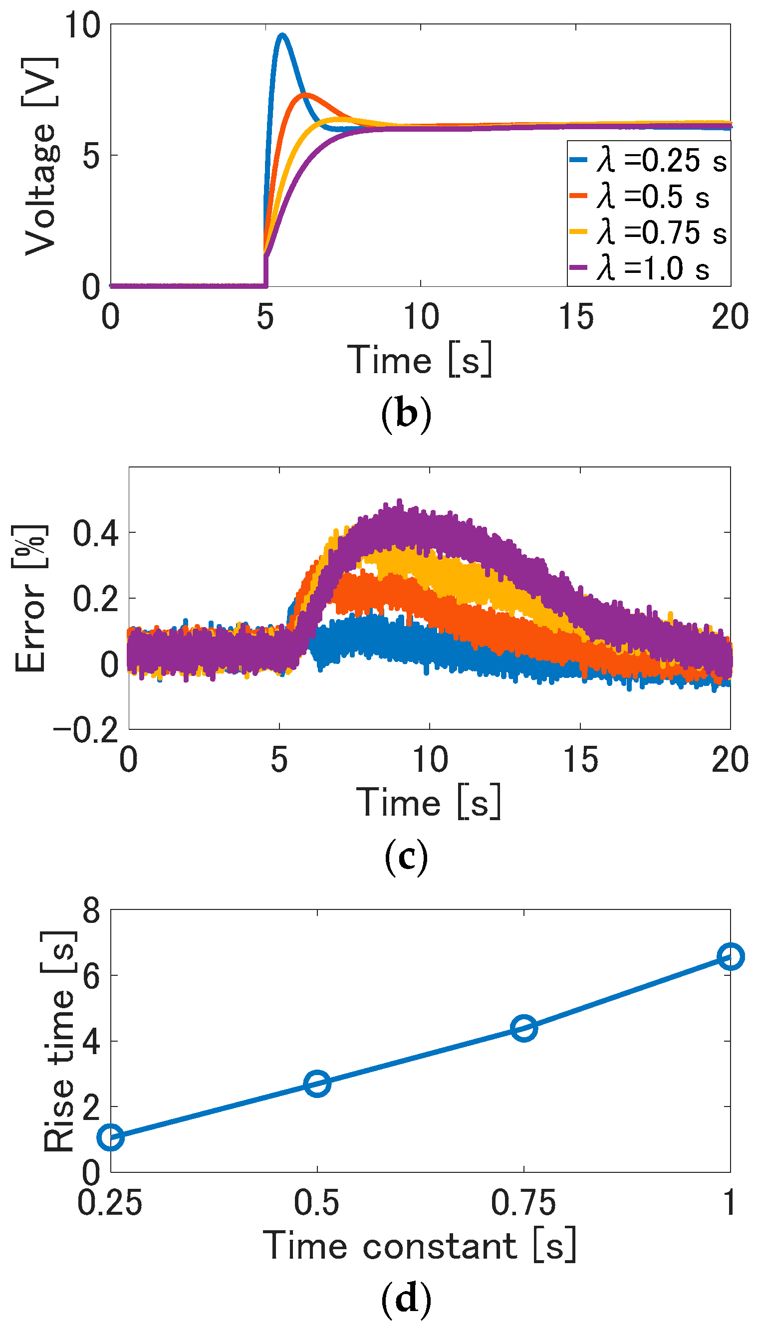
We verified that the proposed control method can realize the desired control performance. Here, as with the method of the reference of Yip and Niemeyer [14], the rise time is recorded when the pole of the reference model is varied. In the experiment, the time constant λ is changed from 0.25 s to 1 s per 0.25 s. Note that the pole is a reciprocal of the time constant λ. The reference signal is the step wave with amplitude of 3 mm. These parameters are determined, so that the control input is not saturated to evaluate the dependence of the time constant.
The experimental results are shown in Figure 10. In this figure, the solid line is the measured displacement, and the dotted line is the desired value. In each result, the displacement converges the reference signals. The response speed is higher, as the time constant is smaller. On the other hand, as the time constant is larger, the response speed from the reference signal to the displacement is slower. Furthermore, the tracking error between the desired value and the displacement increases as the time constant is larger; that is, the tracking performance is higher as the pole is larger. This is considered to arise due to small gain theorem, which is a trade-off between the control performance and stability [36]. From Figure 10d, it is observed that the rise time increases due to the increase of the time constant. As shown in the results, the response from the reference signal to displacement depends on the time constant of the reference model. Therefore, the desired control performance can be realized by adjusting the pole of the reference model.
4. Conclusions
In this paper, we focused on the simple control method of the electroactive TCPA. The internal model control based on the model of the actuator was proposed. The validity of the method was confirmed through the experiments. From various experiment results, the following was confirmed:
- Compared to the conventional feedforward control, the proposed method can cancel the actuator properties adequately and realize the desired control performance.
- The desired control performance can be realized only by adjusting the reference model. Therefore, the control system can be designed easily only by adjusting the reference model if the LTI model of the actuator can be derived.
In the future works, robust control methods for realizing the desired performance will be considered, even if the modeling error is larger due to the aging and the parameter variation, or if a large disturbance is confused. Furthermore, we will apply this control method to applications such as the human robot hand with this actuator, and verify the validity of control methods.
Author Contributions
M.S. designed the control system, fabricated the actuator, constructed the experimental environment, and performed the experiment. Both authors wrote this paper.
Conflicts of Interest
The authors declare no conflict of interest.
References
- Blanc, L.; Delchambre, A.; Lambert, P. Flexible medical devices: Review of controllable stiffness solution. Actuators 2017, 6, 23. [Google Scholar] [CrossRef]
- Laschi, C.; Cianchetti, M. Soft robotics: New perspectives for robot bodyware and control. Front. Bioeng. Biotechnol. 2014, 2, 3. [Google Scholar] [CrossRef] [PubMed]
- Asaka, K.; Oguro, K.; Nishimura, Y.; Mizuhata, M.; Takenaka, H. Bending of polyelectrolyte membrane-platinum composites by electric stimuli I. Response characteristics to various waveforms. Polym. J. 1995, 27, 436–440. [Google Scholar] [CrossRef]
- Kruusamae, K.; Punning, A.; Aabloo, A.; Asaka, K. Self-sensing ionic polymer actuators: A review. Actuators 2015, 4, 17–38. [Google Scholar] [CrossRef]
- Pelrine, E.R.; Roy, D.R.; Jose, P.J. Electrostriction of polymer dielectrics with compliant electrodes as a means of actuation. Sens. Actuators A Phys. 1998, 64, 77–85. [Google Scholar] [CrossRef]
- Gursel, A.; Nam, N.H. Predicting force output of trilayer polymer actuator. Sens. Actuators A Phys. 2006, 616–625. [Google Scholar]
- Fukushima, T.; Asaka, K.; Kosaka, A.; Aida, T. Fully Plastic Actuator through Layer-by-Layer Casting with Ionic-Liquid-Based Bucky Gel. Angew. Chem. Int. Ed. 2005, 117, 2462–2465. [Google Scholar] [CrossRef]
- Kamamichi, N.; Maeba, T.; Yamakita, M.; Mukai, T. Printing fabrication of a bucky gel actuator/sensor and its application to three-dimensional patterned devices. Adv. Robot. 2010, 24, 1471–1487. [Google Scholar] [CrossRef]
- Haines, C.S.; Liam, M.D.; Li, N.; Spinks, G.M.; Foroughi, J.; Madden, J.D.W.; Kim, S.H.; Fang, S.; de Andrade, M.J.; Goktepe, F.; et al. Artificial muscles from fishing line and sewing. Science 2014, 343, 868–872. [Google Scholar] [CrossRef] [PubMed]
- Cho, K.H.; Song, M.G.; Jung, H.; Park, J.; Moon, H.; Koo, J.C.; Nam, J.D.; Choi, H.R. A robotic finger driven by twisted and coiled polymer actuator. Proc. SPIE 2016, 9798, 97981J. [Google Scholar] [CrossRef]
- Yip, M.C.; Niemeyer, G. High-performance robotic muscles from conductive nylon sewing thread. In Proceedings of the 2015 IEEE International Conference on Robotics and Automation, Seattle, WA, USA, 26–30 May 2015. [Google Scholar]
- Edmonds, B.P.R.; Trejos, L.A. stiffness control of a nylon twisted coiled actuator for use in mechatronic rehabilitation devices. In Proceedings of the 2017 IEEE International Conference on Rehabilitation Robotics, London, UK, 17–20 July 2017. [Google Scholar]
- Mirvakili, S.M.; Ravandi, A.R.; Hunter, I.W.; Haines, C.S.; Li, N.; Foroughi, J.; Naficy, S.; Spinks, G.M.; Baughman, R.H.; Madden, J.D.W. Simple and strong: Twisted silver painted nylon artificial muscle actuated by Joule heating. Proc. SPIE 2014, 9056, 90560I. [Google Scholar] [CrossRef]
- Wu, L.; Andrade, M.J.; Rome, R.S.; Haines, C.S.; Lima, M.D.; Baughman, R.H.; Tadesse, Y. Nylon-muscle-actuated robotic finger. Proc. SPIE 2015, 9431, 94310I. [Google Scholar] [CrossRef]
- Wu, L.; Andrade, D.J.M.; Saharan, K.L. Compact and low-cost humanoid hand powered by nylon artificial muscles. Smart Mater. Struct. 2016, 12, 026004. [Google Scholar] [CrossRef] [PubMed]
- Saharan, L.; Andrade, D.J.M.; Saleem, W.; Baughman, H.R. iGrab: Hand orthosis powered by twisted and coiled polymer muscles. Smart Mater. Struct. 2017, 26, 105048. [Google Scholar] [CrossRef]
- Sutton, L.; Moein, H.; Rafiee, A.; Maddan, J.D.W.; Menon, C. Design of an assistive wrist orthosis using conductive nylon actuator. In Proceedings of the IEEE International Conference on Biomedical Robotics and Biomechatronics, Singapore, 26–29 June 2016. [Google Scholar]
- Hiraoka, M.; Nakamura, K.; Arase, H.; Asai, K.; Kaneko, Y.; John, S.W.; Tagashira, K.; Omote, A. Power-efficient low-temperature woven coiled fibre actuator for wearable applications. Sci. Rep. 2016, 6, 36358. [Google Scholar] [CrossRef] [PubMed] [Green Version]
- Wu, L.; Andrade, D.J.M.; Brahme, T.; Tadaesse, Y.; Baughman, H.R. A reconfigurable robot with tensegrity structure using nylon artificial muscles. Proc. SPIE 2016, 9799, 97993K. [Google Scholar] [CrossRef]
- Li, H.; Liu, L.; Xiao, T.; Ang, H. Design and simulative experiment of an innovative trailing edge morphing mechanism driven by artificial muscles embedded in skin. Smart Mater. Struct. 2016, 25, 095004. [Google Scholar] [CrossRef]
- Almubarak, Y.; Maly, N.S.; Tadesse, Y. Fully embedded actuators in elastomeric skin for use in humanoid robots. Proc. SPIE 2018, 10594, 1059416. [Google Scholar] [CrossRef]
- Wu, L.; Karami, F.; Hamidi, A.; Tadesse, Y. Biorobotic systems design and development using TCP muscles. Proc. SPIE 2018, 10594, 1059417. [Google Scholar] [CrossRef]
- Yip, M.C.; Niemeyer, G. On the control and properties of supercoiled polymer artificial muscles. IEEE Trans. Robot. 2017, 33, 687–699. [Google Scholar] [CrossRef]
- Arakawa, T.; Takagi, K.; Tahara, K.; Asaka, K. Position control of fishing line artificial muscles (coiled polymer actuators) from nylon thread. Proc. SPIE 2016, 9798. [Google Scholar] [CrossRef]
- Arakawa, T.; Masuya, K.; Ono, S.; Takagi, K.; Tahara, K. Position control of twisted and coiled polymer actuator using a controlled fan for cooling. Proc. SPIE 2017, 10163. [Google Scholar] [CrossRef]
- Luong, A.T.; Cho, H.K.; Song, G.M.; Koo, C.J.; Choi, R.H.; Moon, H. Nonlinear Tracking Control of a Conductive Supercoiled Polymer Actuator. Soft Robot. 2017, 4, 607–612. [Google Scholar] [CrossRef] [PubMed]
- Suzuki, M.; Kamamichi, N. Displacement control of an antagonistic type of twisted and coiled polymer actuator. Smart Mater. Struct. 2018, 27, 035003. [Google Scholar] [CrossRef]
- Suzuki, M.; Kamamichi, N. Control of twisted and coiled polymer actuator with anti-windup compensator. Smart Mater. Struct. 2018, 27, 075014. [Google Scholar] [CrossRef] [Green Version]
- Astrom, J.K.; Hagglund, T. PID Controllers: Theory, Design, and Tuning, 2nd ed.; ISA (The Instrumentation, Systems, and Automation Society): Research Triangle Park, NC, USA, 1998; pp. 170–180. [Google Scholar]
- Karami, F.; Tadesse, Y. Modeling of twisted and coiled polymer (TCP) muscle based on phenomenological approach. Smart Mater. Struct. 2017, 26, 125010. [Google Scholar] [CrossRef] [Green Version]
- Masuya, K.; Ono, S.; Takagi, K.; Tahara, K. Modeling framework for macroscopic dynamics of twisted and coiled polymer actuator driving by Joule heating focusing on energy and convective heat transfer. Sens. Actuators A Phys. 2017, 267, 443–454. [Google Scholar] [CrossRef]
- Masuya, K.; Ono, S.; Takagi, K.; Tahara, K. Feedforward control of twisted and coiled polymer actuator based on a macroscopic nonlinear model focusing on energy. IEEE Robot. Autom. Lett. 2018, 3, 1824–1831. [Google Scholar] [CrossRef]
- Lamuta, C.; Messelot, S.; Tawfick, S. Theory of the tensile actuation of fiber reinforced coiled muscles. Smart Mater. Struct. 2018, 27, 055018. [Google Scholar] [CrossRef] [Green Version]
- Tang, X.; Liu, Y.; Li, K.; Chen, W.; Zhao, J. Finite element and analytical models for twisted and coiled polymer actuator. Mater. Res. Express 2018, 5, 015701. [Google Scholar] [CrossRef]
- Cho, K.H.; Song, M.G.; Jung, H.; Yang, S.Y.; Moon, H.; Koo, J.C.; Nam, J.; Choi, H.R. Fabrication and modeling of temperature-controllable artificial muscle actuator. In Proceedings of the 2016 6th IEEE International Conference on Biomedical Robotics and Biomechatronics (BioRob), Singapore, 26–29 June 2016. [Google Scholar]
- Morari, M.; Zafirou, E. Robust Process. Control; Prentice Hall: Upper Saddle River, NJ, USA, 1989; pp. 39–56. [Google Scholar]
Figure 1.
The block diagram of the model of the TCPA.

Figure 2.
The block diagram of the control system for the twisted and coiled polymer actuator (TCPA).
Figure 2.
The block diagram of the control system for the twisted and coiled polymer actuator (TCPA).

Figure 3.
The TCPA used in the experiments.

Figure 4.
Experimental environment.

Figure 5.
Identification result: (a) displacement; (b) input voltage.

Figure 6.
Experiment result of the feedforward control with the sinusoidal wave (the solid line: displacement, the dotted line is the desired value): (a) the sinusoidal wave of 0.1 Hz; (b) the sinusoidal wave of 0.025 Hz; (c) the composite wave with the sinusoidal wave of 0.1 Hz and 0.025 Hz.
Figure 6.
Experiment result of the feedforward control with the sinusoidal wave (the solid line: displacement, the dotted line is the desired value): (a) the sinusoidal wave of 0.1 Hz; (b) the sinusoidal wave of 0.025 Hz; (c) the composite wave with the sinusoidal wave of 0.1 Hz and 0.025 Hz.

Figure 7.
Experiment result of the proposed control method with the sinusoidal wave (the solid line: displacement, the dotted line is the desired value): (a) the sinusoidal wave of 0.1 Hz; (b) the sinusoidal wave of 0.025 Hz; (c) the composite wave of 0.1 Hz and 0.025 Hz.
Figure 7.
Experiment result of the proposed control method with the sinusoidal wave (the solid line: displacement, the dotted line is the desired value): (a) the sinusoidal wave of 0.1 Hz; (b) the sinusoidal wave of 0.025 Hz; (c) the composite wave of 0.1 Hz and 0.025 Hz.


Figure 8.
Experiment result of the conventional feedforward control of step response: (a) displacement (the solid line) and the reference signal (the dotted line); (b) input voltage.
Figure 8.
Experiment result of the conventional feedforward control of step response: (a) displacement (the solid line) and the reference signal (the dotted line); (b) input voltage.

Figure 9.
Experimental result of the internal model control in step response: (a) displacement (the solid line) and the reference signal (the dotted line); (b) input voltage.
Figure 9.
Experimental result of the internal model control in step response: (a) displacement (the solid line) and the reference signal (the dotted line); (b) input voltage.

Figure 10.
The response property due to the variation of the time constant λ: (a) displacement (solid line) and the desired value (dotted line); (b) input voltage; (c) tracking error between the displacement and the desired value; (d) rise time vs time constant.
Figure 10.
The response property due to the variation of the time constant λ: (a) displacement (solid line) and the desired value (dotted line); (b) input voltage; (c) tracking error between the displacement and the desired value; (d) rise time vs time constant.


© 2018 by the authors. Licensee MDPI, Basel, Switzerland. This article is an open access article distributed under the terms and conditions of the Creative Commons Attribution (CC BY) license (http://creativecommons.org/licenses/by/4.0/).
Share and Cite
MDPI and ACS Style
Suzuki, M.; Kamamichi, N. Simple Controller Design Based on Internal Model Control for Twisted and Coiled Polymer Actuator. Actuators 2018, 7, 33. https://doi.org/10.3390/act7030033
AMA Style
Suzuki M, Kamamichi N. Simple Controller Design Based on Internal Model Control for Twisted and Coiled Polymer Actuator. Actuators. 2018; 7(3):33. https://doi.org/10.3390/act7030033
Chicago/Turabian StyleSuzuki, Motoya, and Norihiro Kamamichi. 2018. "Simple Controller Design Based on Internal Model Control for Twisted and Coiled Polymer Actuator" Actuators 7, no. 3: 33. https://doi.org/10.3390/act7030033
Note that from the first issue of 2016, this journal uses article numbers instead of page numbers. See further details here.