Effect of Optimal Placement of Permanent Magnets on the Electromagnetic Force in the Horizontal Direction


1
Course of Mechanical Engineering, Tokai University, Kitakaname 4-4-1, Hiratsuka-shi, Kanagawa 259-1292, Japan
2
Department of Prime Mover Engineering, Tokai University, Kitakaname 4-4-1, Hiratsuka-shi, Kanagawa 259-1292, Japan
*
Author to whom correspondence should be addressed.
Actuators 2018, 7(3), 54; https://doi.org/10.3390/act7030054
Submission received: 15 June 2018
/
Revised: 3 August 2018
/
Accepted: 24 August 2018
/
Published: 29 August 2018
(This article belongs to the Special Issue Modeling Smart Actuators and Their Applications)
Abstract
:The surface quality of steel plates is deteriorated as they contact rollers while being conveyed during manufacturing processes. To solve this problem, we previously proposed a hybrid electromagnetic levitation system comprising electromagnets, permanent magnets, and a horizontal positioning control system for steel plates. Moreover, to increase stability, we proposed integrating these levitation systems. In this study, we aim to determine the optimal placement of permanent magnets in the levitation system to suppress the deflection of a levitated steel plate for cases where the magnetic field in the horizontal direction changes. Using a genetic algorithm, the optimal gap, number, and placement of permanent magnets in the system are obtained.
1. Introduction
Permanent magnets can generate constant attractive force and are actively used in various industrial fields. Several studies on electromagnetic levitation technology for ferromagnetic objects have been performed focusing on this feature [1]. In the current steel plate production line, transportation is achieved by contact conveyance by rollers. However, the surface of the steel plate is damaged by this method, and the surface quality of the steel plate deteriorates. With non-contact magnetic levitation transport using the electromagnet proposed by us, these problems can be prevented. These studies consider using the attractive force generated by permanent magnets as a constant suspension force for levitation [2,3]. Although this technology is expected to be applied in the production of high-surface-quality steel plates, the thickness of the steel plate must be decreased to reduce its weight. A steel plate with reduced flexural rigidity owing to its thinness is difficult to levitate in a conventional magnetic levitation system because of exciting elastic vibration. To solve this problem, we proposed a hybrid electromagnetic levitation system for thin steel plates where permanent magnets are installed around electromagnets for levitation [4]. This system can suppress the elastic vibration of levitated steel plates by generating an attractive force on the entire surface of the steel plate using electromagnets and permanent magnets [5]. However, the number of arrangement patterns of the permanent magnets is very enormous, and it is difficult to experimentally obtain a more effective arrangement. Therefore, we focused on genetic algorithm (GA) which is one of optimization algorithms effective for nonlinear objective function [6], which is used to obtain optimum shape of electrical motor in several studies [7,8]. Furthermore, we confirmed that the GA we used to obtain the optimal placement of permanent magnets, considering the interactions of the magnets with each other, improved the levitation stability of the system [9,10]. In addition, we proposed adding another electromagnet in the horizontal direction and positioning controls to the electromagnetic levitation system using vertical electromagnets for levitation [7]. This system generates tension on the edge of the steel plate due to the electromagnetic field generated by the horizontal electromagnets. This tension further suppresses the vibration of the steel plate and improves levitation. In this study, we propose using a hybrid electromagnetic levitation system by applying horizontal positioning control and determine the optimal placement of permanent magnets using a GA for a case where a horizontal electromagnetic field is acting on the steel plate. Furthermore, we performed a levitation experiment and considered the levitation stability of the optimal placement.
2. Outline of the Electromagnetic Levitation System Integrating Permanent Magnets and the Horizontal Positioning Control System
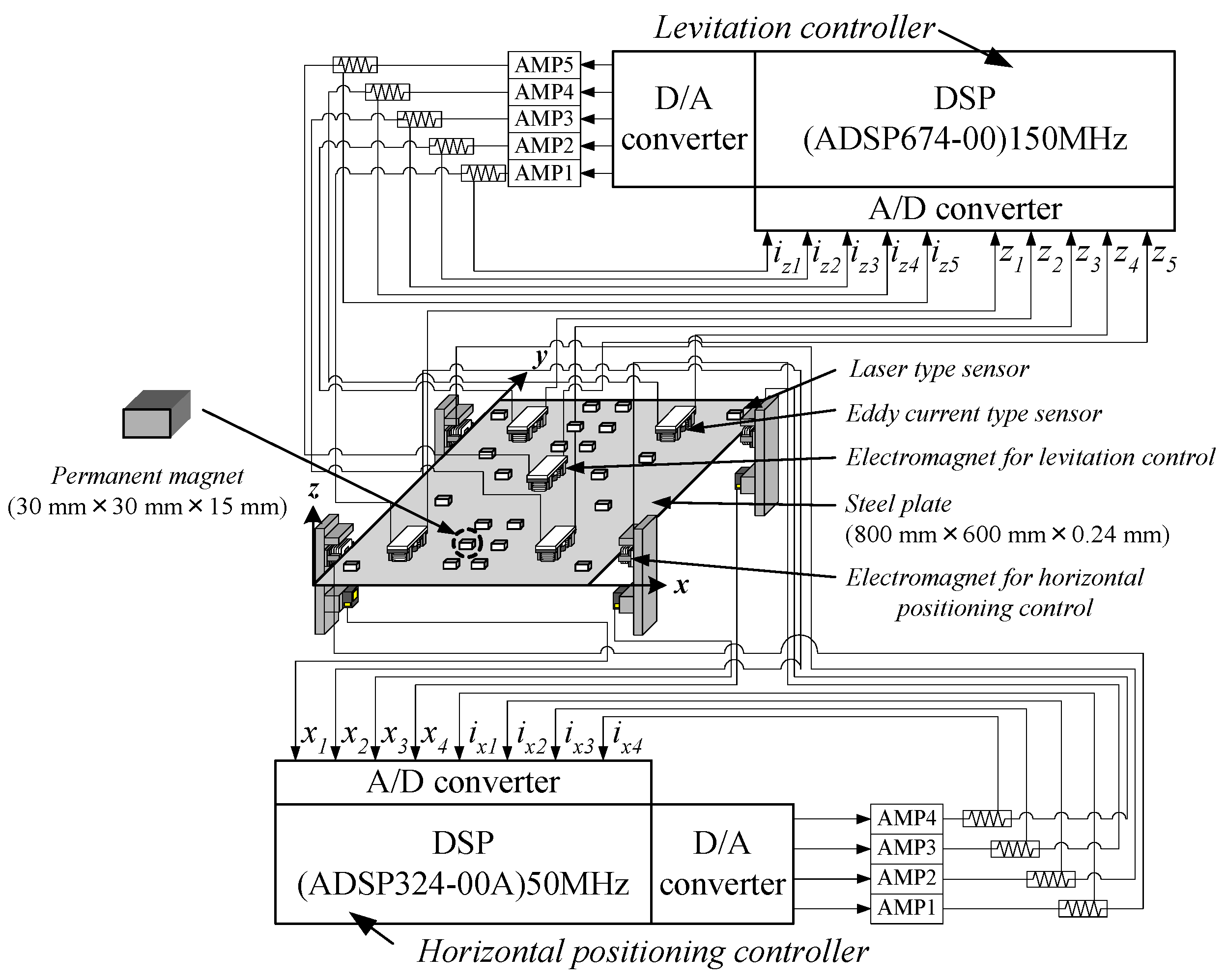
The hybrid electromagnetic levitation system integrating positioning control in the horizontal direction is shown in Figure 1. The object of electromagnetic levitation is a rectangular, zinc-coated steel plate (SS400) with length of 800 mm, width of 600 mm, and thickness of 0.24 mm. To accomplish noncontact support of this plate, as if it were hoisted by strings, we use five pairs of electromagnets (No. 1–5 in Figure 1). The displacement of the steel plate is measured using five eddy-current gap sensors. Here, the electric circuits of paired electromagnets are connected in series, whereas an eddy-current gap sensor is positioned between the two magnets of each pair. The detected displacement is converted to velocity using digital differentiation. A regulated voltage from the digital-to-analog converter is supplied to a current-supply amplifier to control the attractive force of the five pairs of electromagnets to ensure that the steel plate is levitated by 5 mm below the surface of the electromagnets. In this model, independent control is used, wherein information on detected values of displacement, velocity, and coil current of the electromagnet under study are fed back only to the same electromagnet.
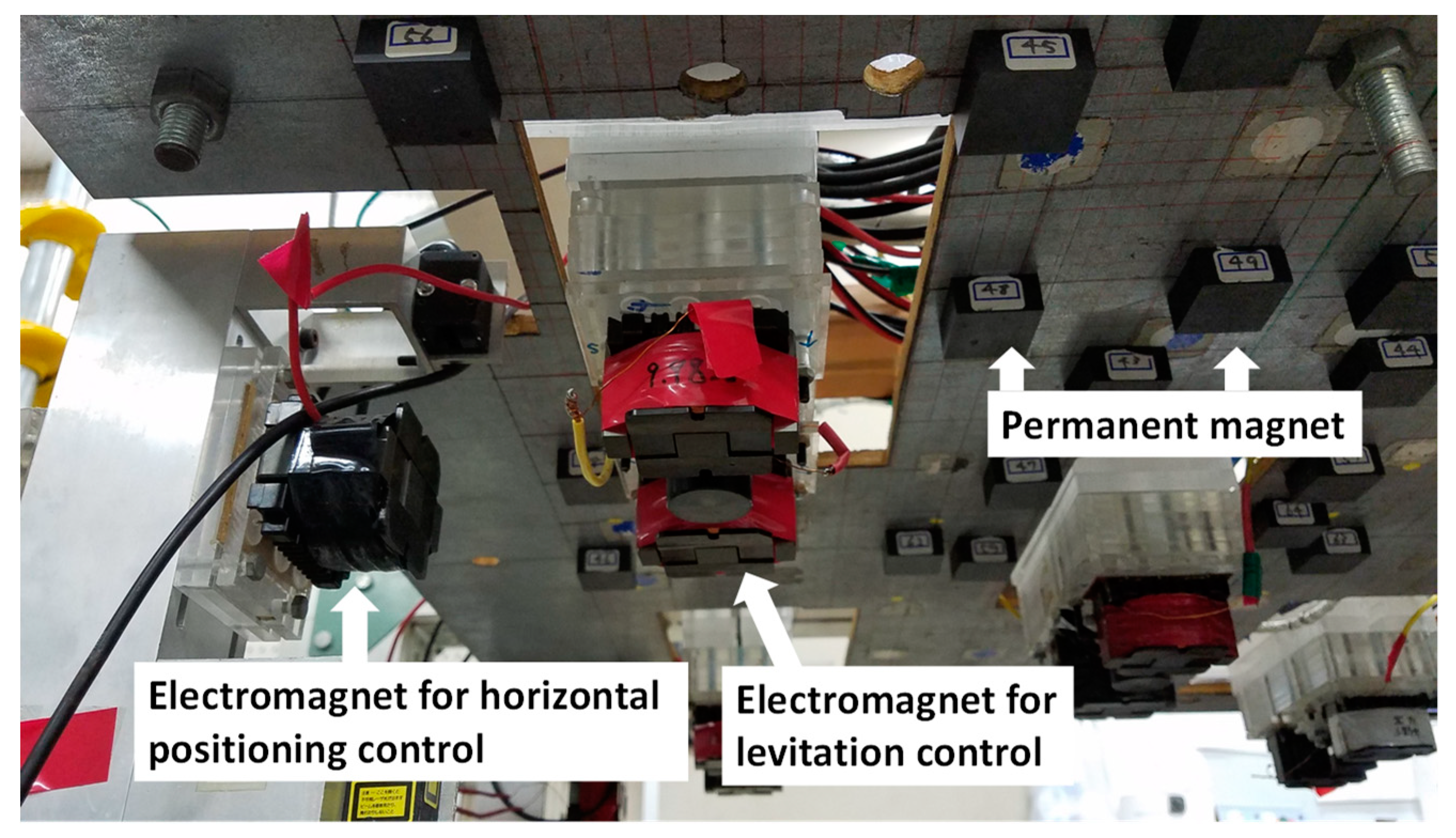
The horizontal displacement of the plate is measured using four laser beam displacement sensors. The four velocities of the plate are detected by differentiating the signals from the displacement sensors using a computer. The current flowing the electromagnet is obtained by measuring the voltage of the resistor connected in series to the electric circuit. The permanent magnets are installed around electromagnet unit for levitation as shown in Figure 2. The size of the permanent magnet for levitation assistance is 30 mm × 30 mm × 15 mm and the material is ferrite. The surface magnetic flux density is 0.12 T. Permanent magnets are placed such that the deflection of the floating steel sheet is suppressed while using the above system.
3. Control Model
3.1. Electromagnetic Levitation Control System
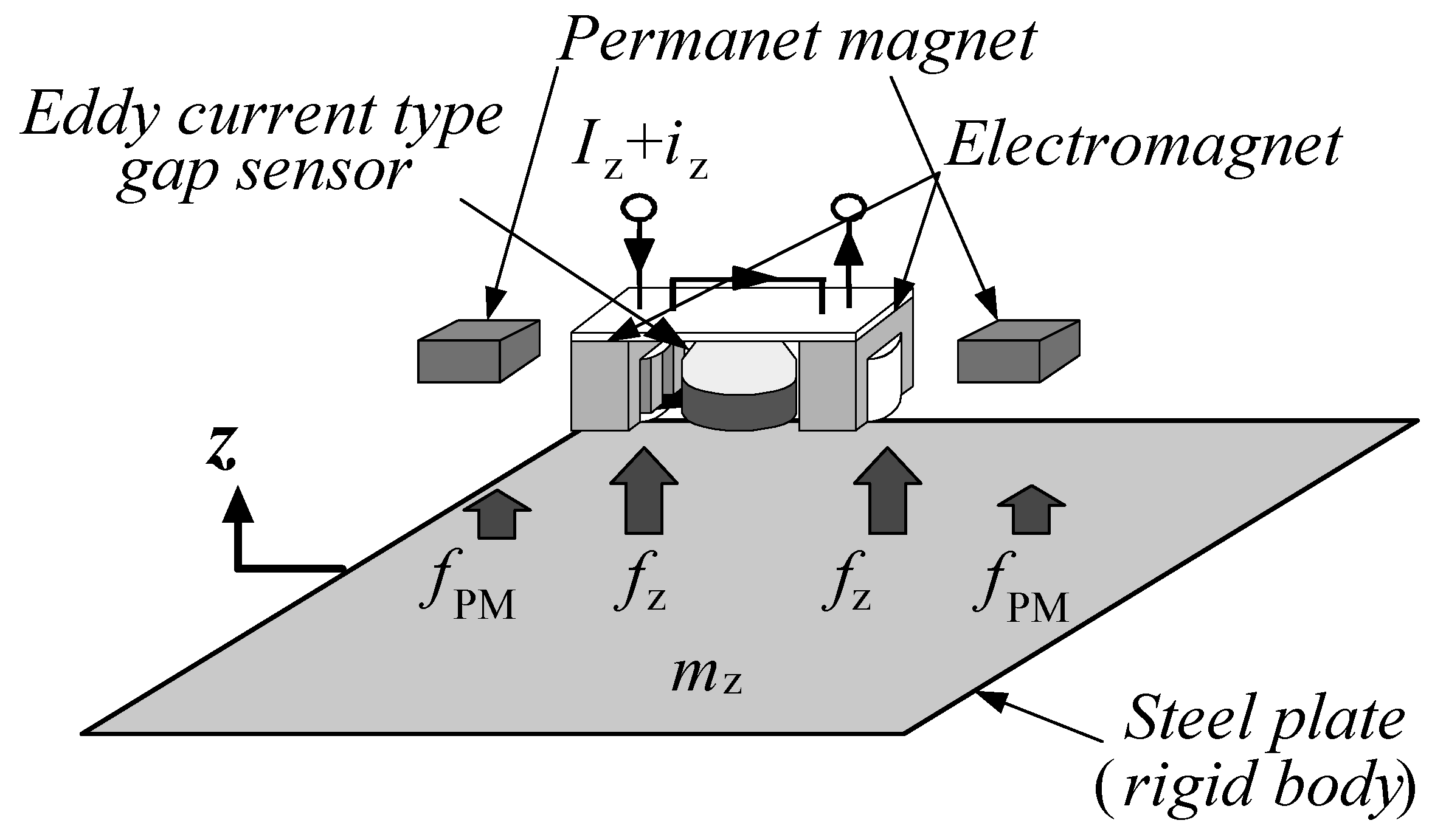
A mathematical control model is formulated to construct the hybrid electromagnetic levitation control system. In this study, each electromagnet unit is controlled by considering the displacement from the gap sensor installed within and the velocity and current of the electromagnet unit. Therefore, the control model for levitation is established in each unit. Figure 3 shows the model of levitation control for one electromagnet unit using the lumped parameter system. From previous study, it is confirmed that by placing permanent magnets, the deflection of the steel plate is suppressed, and the levitation stability improves [9,10,11]. From this result, the steel plate was assumed to be a rigid body. The steel plate is virtually divided into five hypothetical masses. In an equilibrium levitation state, a constant attractive force equal to the weight of the virtually divided steel plate needs to be generated by the electromagnet, and the change of the attractive force from the equilibrium state causes the motion of the virtually divided steel plate. The vertical motion of the steel plate is expressed as follows.
We defined on the assumption that the inductance of one coil is expressed by the sum of the effective inductance inversely proportional to the gap and the leakage inductance [12]. Since the two electromagnets are not magnetically connected, mutual inductance is not considered.
Using the state vector, Equations (1)–(4) are written as the following state equations.
Furthermore, vz is calculated by the state feedback control of Equation (6).
3.2. Horizontal Positioning Control System
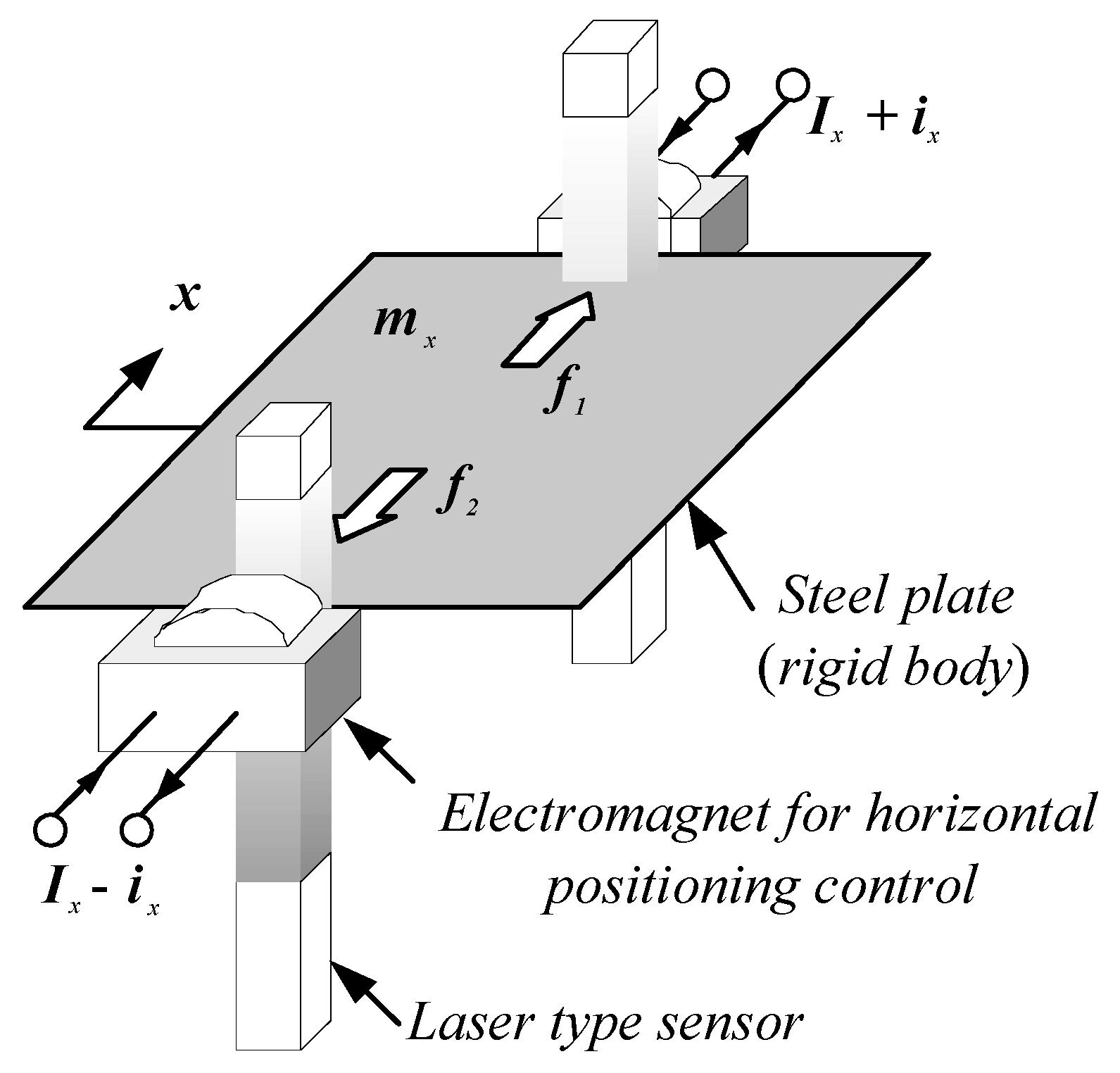
The horizontal motion of the steel plate was modeled to have a single degree of freedom, as shown in Figure 4. Therefore, the same attractive forces were generated from the two electromagnets placed at one side of the steel plate. The equation for small horizontal motion around the equilibrium state of the steel plate subjected to the same static magnetic forces from the electromagnets at two edges is expressed as follows.
Using the state vector, Equations (7)–(10) can be written as the following state equations.
Here, the control signal is expressed as follows.
4. Determination of Optimal Placement
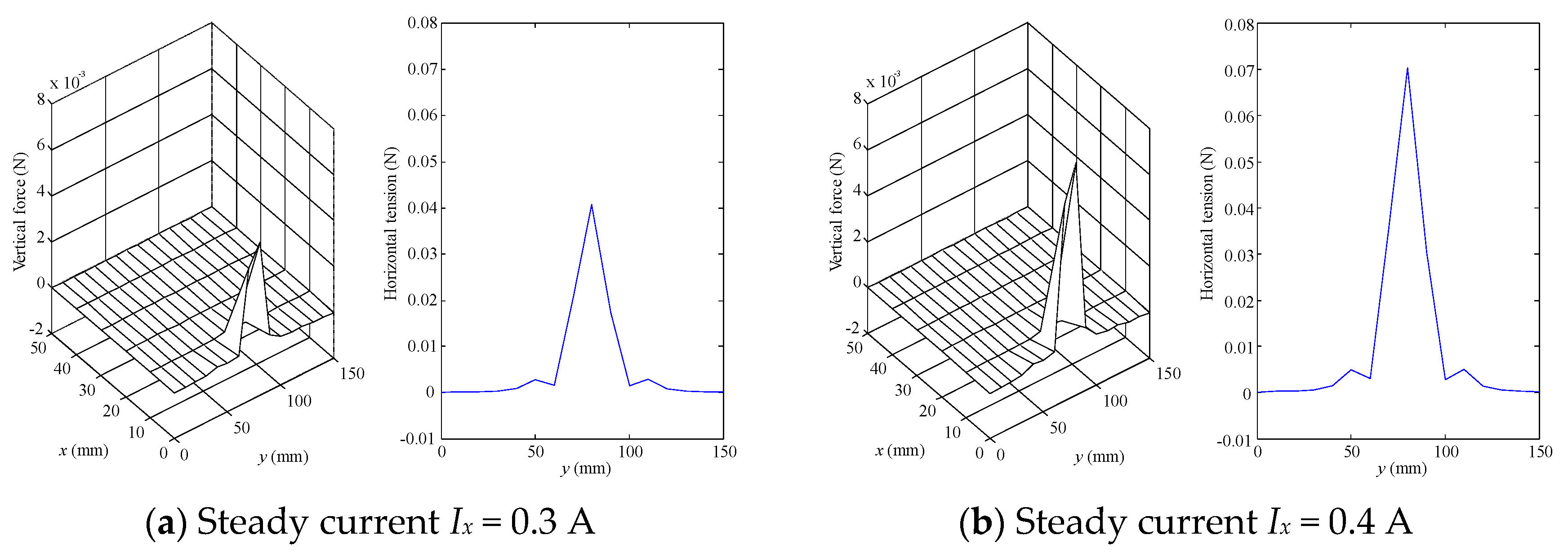
In the proposed system, by applying the attractive force of the permanent magnet to the area where the attractive force of the electromagnet is lacking, the deflection of the levitating thin steel plate is suppressed and the levitation stability of the system is improved, which is the aim of this study. However, experimentally searching for the optimal placement of the permanent magnets is practically impossible because of the large number of combinations of the search patterns. Searching is performed in the range where the steel plate is divided into ¼, and the position of the PM can be arranged at intervals of 10 mm, considering the size of PM and the range of EM. Furthermore, the maximum number of PMs is set to 15, and the search is performed within the range of 40 mm to 80 mm for Gap [9,10]. In addition, optimal placement is sought by considering interaction of PM by past research [11]. The magnetic field applied by the horizontal electromagnet was analyzed by JMAG, as shown in Figure 5.
We calculated the deflection of the thin steel plate by solving Equation (13), which express the bending of the plate when the lateral load and the force in the central plane coexist [13], using the finite differential method. Moreover, we used Equation (13), considering permanent magnets and horizontal electromagnets, to obtain the optimal placement of the permanent magnets by GA during levitation when the attractive force of the permanent magnets is applied. Owing to the large number of combinations of the search patterns, the evaluation function J is defined as Equation (14) to evaluate average deflection of the steel plate and local deflection.
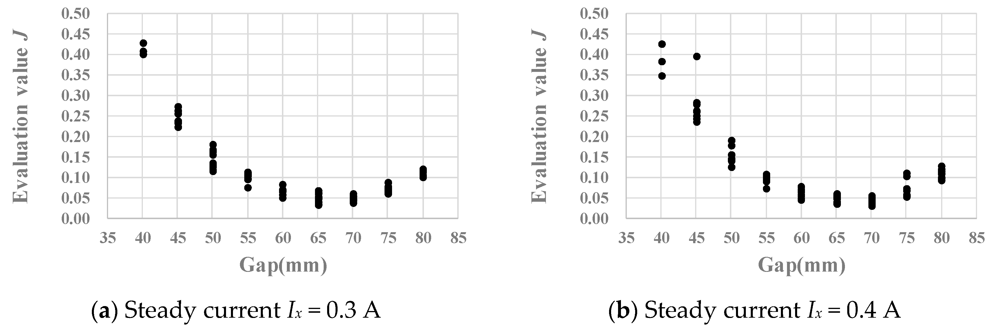
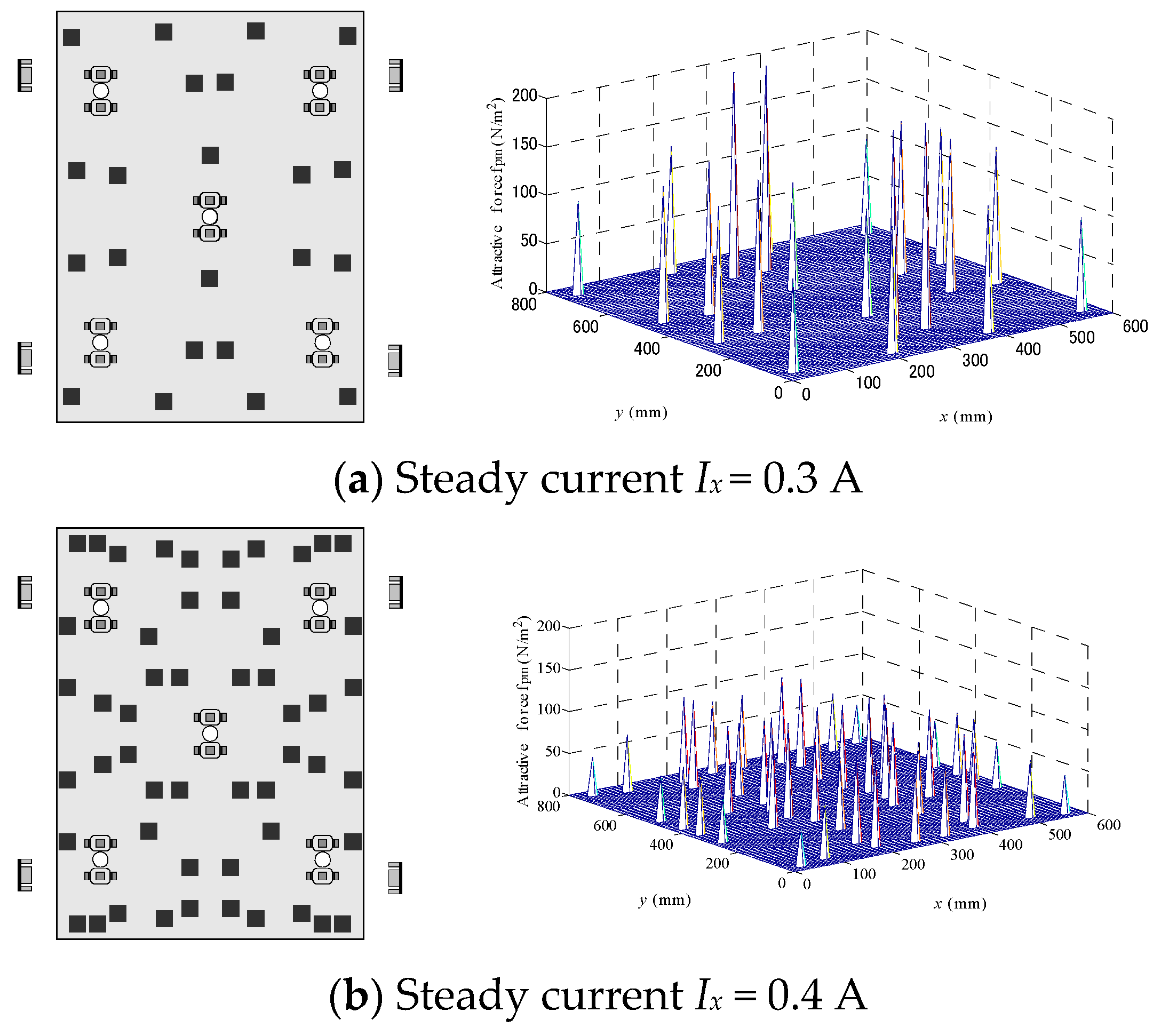
The evaluation value J becomes 1 when the permanent magnets are not installed. It is shown that the shape of the thin steel plate is improved when the evaluation value J is small. The shape of the thin steel plate that reduces the evaluation value J is determined from the deflection of the plate. Figure 6a,b show the relation between the gap, defined as the distance from the permanent magnets to the steel plate, and the evaluation value J in the search result. The left sides show the obtained optimal placement of permanent magnets. Figure 7a,b show the results when the steady currents of the horizontal electromagnet Ix are 0.3 A and 0.4 A, respectively. The results of this analysis show that the optimal number of permanent magnets at 0.4 A is larger than that at 0.3 A. It is reasonable to assume that the optimal gap at 0.4 A is larger than that at 0.3 A because of the increase of the attractive force from the horizontal electromagnets. Therefore, as the attractive force of each permanent magnet decreases, the placement with the optimal gap requires more permanent magnets.
5. Magnetic Levitation Experiment Using Optimal Placement
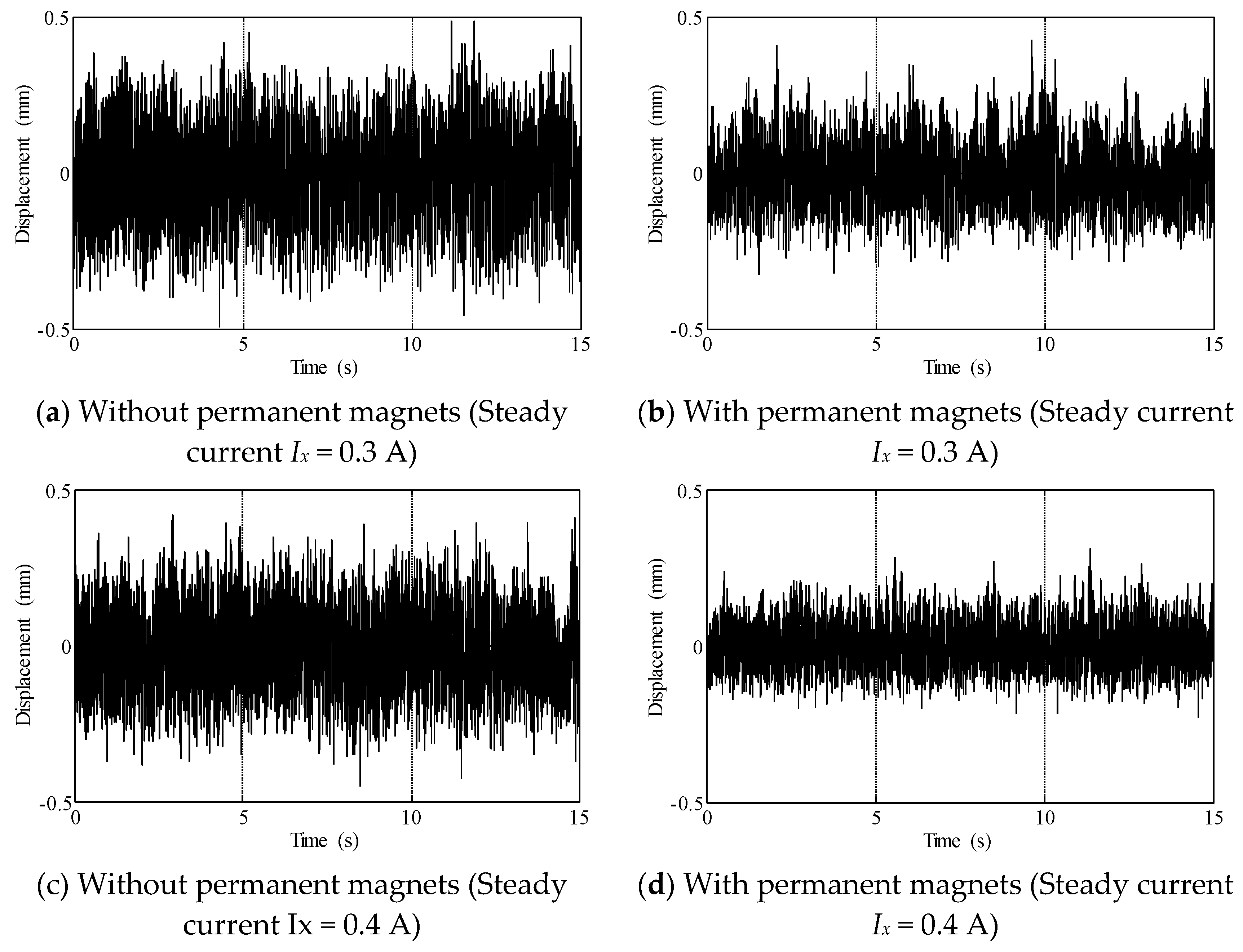
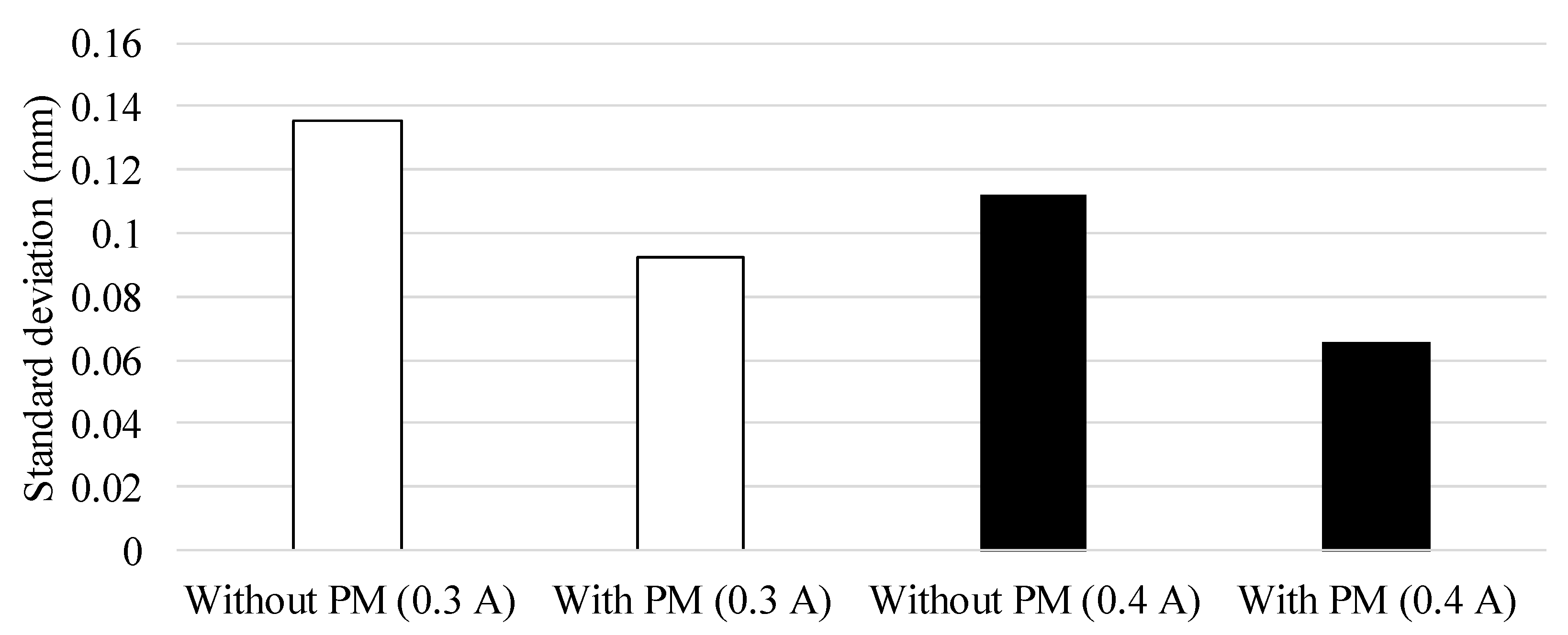
To evaluate the optimal placement obtained by a GA, levitation experiments were conducted for cases where permanent magnets were installed and those wherein permanent magnets were not installed in the levitation system. A distance of 5 mm was maintained between the surface of the steel plate and the levitation electromagnets and between the edge of the steel plate and the horizontal positioning control electromagnets. Based on analytical results, the steady current Ix was set to 0.3 and 0.4 A. Figure 8 shows the time histories of the measured displacement of the steel plate by the eddy-current sensor installed in the central electromagnet unit and the experimental results with and without permanent magnets. Figure 8a,b show the results when the steady current Ix is 0.3 A and Figure 8c,d show the results when Ix is 0.4 A. For each steady current, when permanent magnets are installed in the optimal placement, the vibration of the levitated steel plate can be suppressed. Figure 9 shows the comparison of the displacement standard deviations for each steady current. In this system, the steel plate deflects where electromagnetic force does not reach the steel plate. It is considered that this bending portion is the cause of the vibration of the steel plate. Furthermore, we consider that bending was suppressed by attaching PM and vibration was suppressed. These results show the validity of searching for the optimal placement of permanent magnets by a GA and the effectiveness of permanent magnets for vibration suppression when the magnetic field generated by the horizontal electromagnets is changed.
6. Conclusions
We determined the optimal number, gap, and placement of permanent magnets in the levitation system to suppress the deflection of a levitated steel plate when the magnetic field acting on it is generated from the horizontal direction. The levitation experiments were performed by applying the obtained optimal placements of permanent magnets. The results show that the optimal placement of permanent magnets can improve the levitation stability of the system even if the horizontal magnetic field changes. This supports the possibility of more stable transport methods for levitated steel plates using optimal placements of permanent magnets.
Author Contributions
Y.I., Y.O., T.N. and H.K. wrote the paper; Y.I. and Y.O. performed the experiments; Y.I. and Y.O. contributed the analysis of the data; and T.N. and H.K. contributed to the design of the controller and electric circuit. T.N. and H.K. contributed to analysis optimal placements of permanent magnets.
Funding
This research received no external funding.
Acknowledgments
We would like to show our greatest appreciation to Toshiki Suzuki and Masahiro Kida.
Conflicts of Interest
The authors declare no conflict of interest. The founding sponsors had no role in the design of the study; collection, analyses, or interpretation of data; writing the manuscript; and decision to publish the results.
Nomenclature
The definitions of symbols used in this study are as follows:
| E | Young’s modulus of the thin steel plate (N/m2) |
| f | vertical static magnetic force applied to the plate, which is generated by the permanent magnets (N/m2) |
| fz | dynamic magnetic force (N) |
| Fx | magnetic force of the coupled magnets in the equilibrium state (N) |
| Fz | magnetic force of the coupled magnets in the equilibrium state (N) |
| g | acceleration due to gravity (m/s2) |
| h | plate thickness (m) |
| iz | dynamic current of the coupled electromagnets (A) |
| ix | dynamic current of the coupled magnets (A) |
| Ix | current of the coupled magnets in the equilibrium state (A) |
| Iz | current of the coupled electromagnets in the equilibrium state (A) |
| JD | evaluation function of the maximum deflection (m) |
| Jz | evaluation function of the average absolute deflection (m) |
| Llea | leakage inductance of one magnet coil (H) |
| Lx | inductance of one magnet coil in the equilibrium state (H) |
| Lxlea | leakage inductance of one magnet coil (H) |
| Lxeff/X0 | effective inductance of one magnet coil (H) |
| Lz | inductance of one electromagnet coil in the equilibrium state (H) |
| mz | virtually divided steel plate (kg) |
| N | the total number of analysis points |
| Rx | resistance of the coupled magnet coils (Ω) |
| Rz | resistance of the coupled magnet coils (Ω) |
| Ts | sampling time (s) |
| ν | Poisson ratio |
| vx | dynamic voltage of the coupled magnets (V) |
| vz | dynamic voltage of the coupled magnets (V) |
| x | coordinates in the width direction (m) |
| X0 | gap between the steel plate and electromagnet in the equilibrium state (m) |
| y | coordinates in the longitudinal direction (m) |
| z | vertical displacement from the equilibrium state (m) |
| zi | displacement at each analysis point on the thin steel plate (m) |
| zmax | maximum deflection of the thin steel plate (m) |
| Z0 | gap between the steel plate and electromagnet in the equilibrium state (m) |
| ρ | plate density (kg/m3) |
References
- Onuki, T.; Toda, Y. Optimal design of hybrid magnet in maglev system with both permanent and electromagnets. IEEE Trans. Magn. 1993, 29, 1783–1786. [Google Scholar] [CrossRef]
- Oka, K.; Higuchi, T. 3 Degree of freedom maglev system with actuators and permanent magnets. IEEJ Trans. Ind. Appl. 1995, 115, 294–300. [Google Scholar] [CrossRef]
- Morishita, M.; Ito, H. The self-gap-detecting zero power controlled electromagnetic suspension system. IEEJ Trans. Ind. Appl. 2006, 126, 1667–1677. [Google Scholar] [CrossRef]
- Kamijo, Y.; Ito, H.; Maruyama, Y. Structure and characteristic of magnetic bearing with zero power controlled electromagnetic suspension. Trans. Jpn. Soc. Mech. Eng. Ser. C 2013, 79, 4963–4972. [Google Scholar] [CrossRef]
- Oshinoya, Y.; Ishibashi, K. Development of electromagnetic levitation control device for a rectangular sheet steel. Trans. Jpn. Soc. Mech. Eng. Ser. C 2001, 661, 2855–2862. [Google Scholar] [CrossRef]
- Goldberg, D.E. Genetic Algorithms in Search, Optimization, and Machine Learning; Addison-Wesley Professional: Boston, MA, USA, 1989; ISBN 978-0201157675. [Google Scholar]
- Mallik, S.; Mallik, K.; Barman, A.; Maiti, D.; Biswas, S.K.; Deb, N.K.; Basu, S. Efficiency and cost optimized design of an induction motor using genetic algorithm. IEEE Trans. Ind. Electron. 2017, 64, 9854–9863. [Google Scholar] [CrossRef]
- Okamoto, Y.; Tominaga, Y.; Wakao, S.; Sato, S. Topology optimization of rotor core combined with identification of current phase angle in IPM motor using multistep genetic algorithm. IEEE Trans. Magn. 2014, 50, 725–728. [Google Scholar] [CrossRef]
- Narita, T.; Hasegawa, S.; Oshinoya, Y. Optimal placement of permanent magnets in a hybrid magnetic levitation system for thin steel plate (experimental consideration on levitation probability). Proc. Sch. Eng. Tokai Univ. 2013, 38, 59–66. [Google Scholar]
- Narita, T.; Hasegawa, S.; Oshinoya, Y. Hybrid electromagnetic levitation system for thin steel plates using permanent magnets. J. Magn. Soc. Jpn. 2013, 37, 29–34. [Google Scholar] [CrossRef]
- Ishii, H.; Narita, T.; Kato, H. Hybrid magnetic levitation system for thin steel plate by electromagnets and permanent magnets (basic study on optimal placement search considering the interaction of the magnetic field). J. Jpn. Soc. Appl. Electromagn. Mech. 2016, 24, 149–154. [Google Scholar] [CrossRef]
- Chiba, A.; Fukao, T.; Ichikawa, O.; Oshima, M.; Takemoto, M.; Dorrell, D.G. Magnetic Bearings and Bearingless Drives; Elsevier: Boston, MA, USA, 2005; p. 20. ISBN 9780750657273. [Google Scholar]
- Timoshenko, S.P.; Woinowsky-Krieger, S. Theory of Plate and Shells; McGraw-Hill Publishing Company: New York, NY, USA, 1959. [Google Scholar]
Figure 1.
Hybrid electromagnetic levitation system integrating positioning control in the horizontal direction.
Figure 1.
Hybrid electromagnetic levitation system integrating positioning control in the horizontal direction.

Figure 2.
Photograph of the placement of permanent magnets around the levitation electromagnets.

Figure 3.
Modeling of levitation control for one electromagnet unit by lumped parameter system.

Figure 4.
Theoretical model of the horizontal positioning control of the steel plate.

Figure 5.
Analysis result of magnetic field (horizontal electromagnet).

Figure 6.
Evaluation value vs. gap in consideration of changed horizontal steady current.

Figure 7.
Optimal placement of permanent magnets considering the horizontal attractive force and distribution of the attractive force acting on the steel plate.
Figure 7.
Optimal placement of permanent magnets considering the horizontal attractive force and distribution of the attractive force acting on the steel plate.

Figure 8.
Time history of displacement at each steady current of the horizontal electromagnet.

Figure 9.
Displacement standard deviation of the levitation direction of each horizontal steady current.
Figure 9.
Displacement standard deviation of the levitation direction of each horizontal steady current.


Table 1.
The value of each parameter.
| Parameters | Values |
|---|---|
| m | 0.864 kg |
| E | 206 GPa |
| ν | 0.3 |
| Z0 | 5 × 10⁻³ m |
| Rn | 21.0 Ω |
| Leff | 2.55 × 10⁻⁴ Hm |
| Llea | 0.090 H |
| Ts | 0.001 s |
© 2018 by the authors. Licensee MDPI, Basel, Switzerland. This article is an open access article distributed under the terms and conditions of the Creative Commons Attribution (CC BY) license (http://creativecommons.org/licenses/by/4.0/).
Share and Cite
MDPI and ACS Style
Ito, Y.; Oda, Y.; Narita, T.; Kato, H. Effect of Optimal Placement of Permanent Magnets on the Electromagnetic Force in the Horizontal Direction. Actuators 2018, 7, 54. https://doi.org/10.3390/act7030054
AMA Style
Ito Y, Oda Y, Narita T, Kato H. Effect of Optimal Placement of Permanent Magnets on the Electromagnetic Force in the Horizontal Direction. Actuators. 2018; 7(3):54. https://doi.org/10.3390/act7030054
Chicago/Turabian StyleIto, Yasuaki, Yoshiho Oda, Takayoshi Narita, and Hideaki Kato. 2018. "Effect of Optimal Placement of Permanent Magnets on the Electromagnetic Force in the Horizontal Direction" Actuators 7, no. 3: 54. https://doi.org/10.3390/act7030054
Note that from the first issue of 2016, this journal uses article numbers instead of page numbers. See further details here.