Article

Directional Stiffness Control Through Geometric Patterning and Localized Heating of Field’s Metal Lattice Embedded in Silicone

School of Mechanical and Materials Engineering, Washington State University, Pullman, WA 99164, USA
*
Author to whom correspondence should be addressed.
Current address: WSU M3 Robotics Laboratory, Dana 250, 305 NE Spokane Street, Pullman, WA 99164, USA.
Actuators 2018, 7(4), 80; https://doi.org/10.3390/act7040080
Submission received: 1 October 2018 / Revised: 13 November 2018 / Accepted: 21 November 2018 / Published: 27 November 2018
(This article belongs to the Special Issue New Materials and Designs for Soft Actuators)

Abstract

:
This research explores a new realm of soft robotic materials where the stiffness magnitude, directionality, and spatial resolution may be precisely controlled. These materials mimic biological systems where localized muscle contractions and adjustment of tissue stiffness enables meticulous, intelligent movement. Here we propose the use of a low-melting-point (LMP) metal lattice structure as a rigid frame using localized heating to allow compliance about selectable axes along the lattice. The resulting shape of the lattice is modeled using product of exponentials kinematics to describe the serial chain of tunably compliant axes; this model is found to match the behavior of the physical test piece consisting of a Field’s metal (FM) lattice encased in silicone rubber. This concept could enable highly maneuverable robotic structures with significantly improved dexterity.

1. Introduction

Soft robotics and compliant robotic mechanisms have become increasingly popular over the last few years as their soft, compliant nature makes them safe for interaction with humans and ideal for applications that require adaptability, such as in squeezing through tight spaces or grasping objects [1,2,3]. Most soft robotics research is aimed toward addressing key challenges such as achieving energy efficiency, meeting perceptual demands required for human interaction, achieving high strength while maintaining flexibility, and mimicking seemingly simple human capabilities that require complicated control algorithms and unintuitive physical design [4,5].
Many soft robotic actuators are fabricated using elastomeric materials activated by pneumatic chambers that deform the elastomer when pressurized [6,7,8,9,10]. Fiber reinforcements and high pressure within the pneumatic chambers enable these hands and grippers to exert substantial forces [3,11,12]. Other soft actuators are fabricated with thin electrode coatings on both sides of an elastomer that cause deformation of the elastomer when a high voltage is applied across the electrodes [9]. 4D printing has been employed to enable self-bending of spatial assemblies upon stimulation via heat, light, electricity, etc. [13]. These methods involve patterned deposition of ink to induce localized heating/shrinkage under infrared irradiation or spatially controlled swelling of a medium within a polymer matrix [13,14]. Despite significant progress toward innovative soft actuation mechanisms that enable mobility and flexibility, soft actuators have yet to match the capabilities of natural muscle in terms of combined strength, flexibility, and compactness [9,10].
Progress in this field is limited by a need for robotic structures that can offer both high strength and adaptability. This may be achieved by modifying pre-existing rigid robots to allow compliant behavior under certain conditions, or alternatively by adding tunable stiffness to compliant soft robotic structures. Many biological systems operate by adjusting the stiffness of tissues and contracting localized muscle groups to achieve directional stiffness while allowing flexibility in some directions [15]. These biological concepts are brilliant, and they serve as inspiration for this research field [7,16,17].
Progress has been made toward the development of variable stiffness materials as a means of stiffening soft robotic structures. Researchers have developed materials with stiffness magnitudes that may be controlled by a temperature stimulus. These materials typically consist of a low-melting-point (LMP) metal alloy or a rigid rubber encased in an elastomer; when heated, the rigid material melts or softens, making the composite material flexible [18,19,20,21]. Thus, robotic materials may transform form rigid structures to soft, compliant members upon melting of a rigid internal skeleton.
Some effort has been made toward exploration of directional stiffness control in soft robotic mechanisms. Typically, pneumatically actuated soft robots operate by pressurizing chambers solely as a means of achieving motion of the robot, but a pneumatically actuated soft robot has been developed that offers simultaneous control of both stiffness and position through the pressurization of antagonistic chambers [22]. Still, there exists a need for stronger variable stiffness robotic elements that offer directional stiffness control. By heating localized segments of an LMP material rod encased in an elastomer, bending may be induced at different locations along the rod [20,21]. Extending this idea of controllable compliance locations onto more advanced geometric structures could allow for intricate control of directional stiffness. As reviewed by Laschi et al. [1], two main approaches are used in stiffening soft bodies: antagonistic arrangement of soft actuators, and semiactive actuators with stiffness variability. This work falls under the latter category where the ability to locally control stiffness is the primary objective. The focus is no longer just on the method of stiffening, as reviewed by Manti [23], but on how the geometry of the underlying materials provide greater ability to manipulate the soft robotic component and the surrounding environment.
The proposed work is directed toward the goal of stiffness control in directionality and spatial resolution. Rather than focusing purely on the adjustability of overall material stiffness magnitude, this research focuses on the development of a device that exhibits both a larger scale of stiffness levels, and increased spatial control over the axes of compliance. Here a Field’s metal (FM) lattice structure is encased in silicone with localized heating elements that allow control over the axes of compliance. This work is aimed at testing the hypothesis that added capability of greater dexterity and precision in exertion of forces on the environment, as well as improved control of the soft robotic mechanism is attainable through geometric patterning and localized temperature control. A model of the compliant structure is developed by approximating compliant joints as revolute joints with pseudo-rigid body modeling [24,25].
Development of complete forward kinematics to describe the motion of the robotic element could allow for precise control of robotic elements as illustrated in Figure 1. Applications in the soft robotics field could enable highly dexterous fingers or end extenders that are far less kinematically limited than conventional grasping mechanisms.

2. Materials and Methods

2.1. Test Piece Fabrication

A test piece consisting of an FM lattice encased in a thin silicone matrix is fabricated to demonstrate the directional stiffness controllability that can be achieved through localized heating. Figure 2 shows the step-by-step fabrication process for the test piece. First, a mold is 3D printed out of Polyvinyl alcohol (PVA) following fabrication methods proposed by Swensen et al. [26] with hollow, diamond-shaped channels inside for the FM. The diamond shape of the channels eliminates the need for printing support material in the mold. An injection hole and tiny vent holes are drilled in the top of the mold after printing to allow air to escape as the FM is injected with a syringe. After the metal solidifies in the channels, the mold is submerged in water for two days until the PVA mold is completely dissolved, exposing the bare FM lattice. The silicone matrix is then cast in layers to ensure proper spacing between components and prevent direct contact between the Nichrome heating elements and the FM lattice.

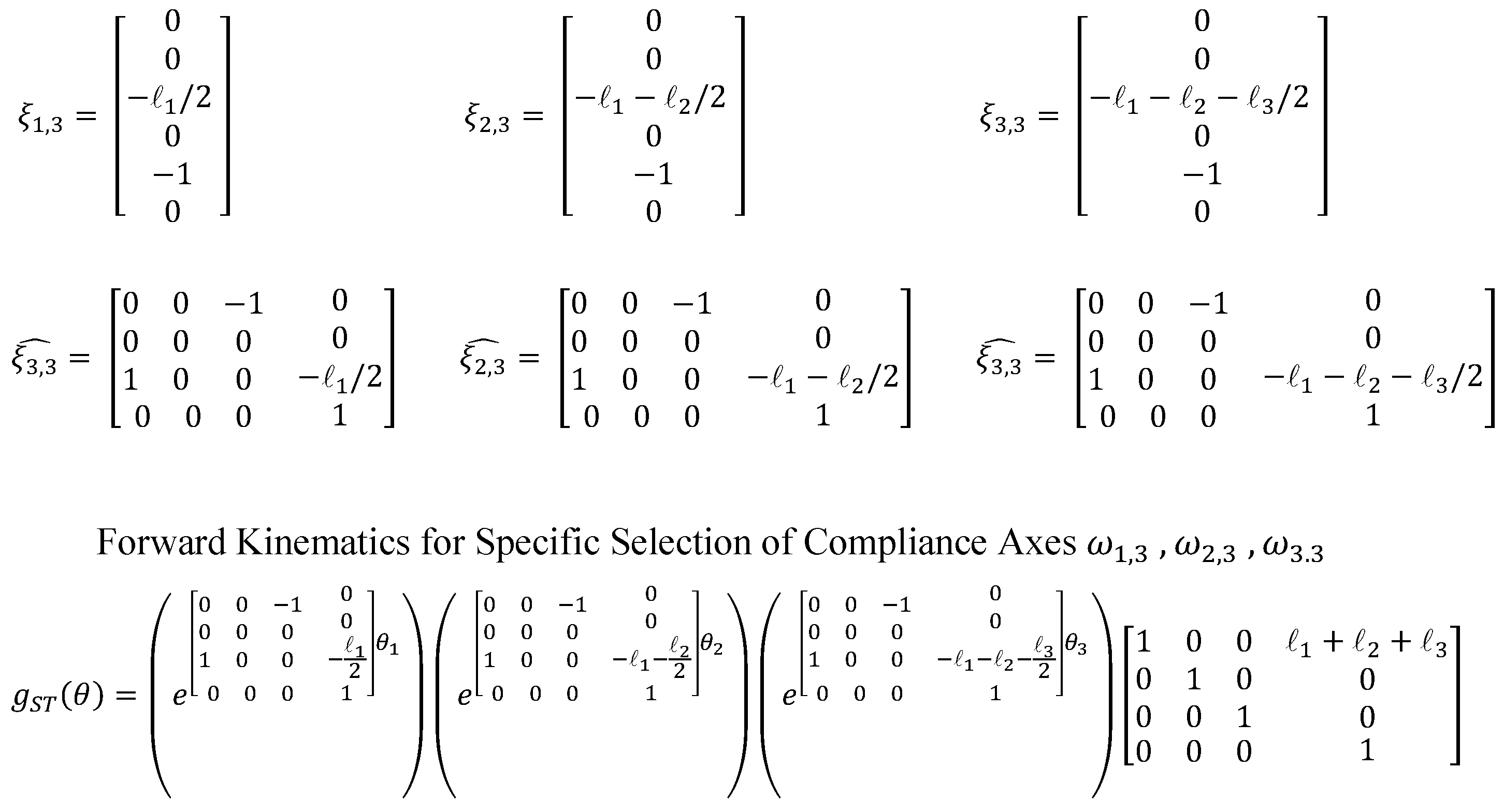
2.2. Deriving Forward Kinematics with Changing Axes of Compliance

Using the language of differential geometry represented as Lie groups and Lie algebras [27], rigid body transforms between coordinate frames are often represented in terms of the exponential map from the Lie algebra SE(3) to the Lie group SE(3). In the general case, given a function of instantaneous velocities represented as the screw ξ ^ ( t ) SE(3), with ^ : R 6 SE(3) the isomorphism between the reals and the Lie algebra, the relationship between the instantaneous velocities and the corresponding coordinate frame transformation is
g a b ( t ) = e 0 t ξ τ d τ g a b ( 0 ) , g a b ( t ) S E ( 3 ) .
In the particular case where the instantaneous velocities can be written as the product of a constant twist and a time-varying parameter, ξ ^ ( t ) = ξ c ^ q ( t ) , the treatment of g a b ( t ) and its time derivatives are greatly simplified. The tunably compliant FM test piece here is explicitly designed such that constant twists describe its motion in each of the tunably compliant configurations. This behavior is observable in Figure 3 where its bending along each of the axes can be described by a constant twist multiplied by a bend angle. Then, the serial chain of tunably compliant axes may be described as a product of exponentials where the direction of compliance of each segment is parameterized by an associated constant twist and joint motions,
g S T ( q ) = e ξ 1 q 1 ( t ) e ξ 2 q 2 ( t ) e ξ n q n ( t ) g S T ( 0 ) .
This type of kinematic simplification is demonstrated in Figure 3 for a 3-segment case of the LMP truss fabricated for this experiment. In this example, two heaters in each segment allow the truss to be melted along either diagonal axis, w i , 1 or w i , 2 , or when both are heated simultaneously the axis of rotation is w i , 3 . The elastomer elements surrounding the low-melting-point metals can be modeled as a torsional spring about the axis of compliance cause by the melted metal. This approach relies on mechanism simplifications for compliant mechanism pioneered by Howell [28], where compliant joints are considered using pseudo-rigid body modeling with joints that are not fixed. Thus, the tendon force to mechanism configuration can be solved through a combination of the forward kinematics, associated Jacobian, and the tendon routing and tension force. As shown in Figure 3, the axis directions w i , i , a point that lies on the selected axis q i , and the reference configuration g S T ( 0 ) (defined where all joint angles are zero) are used to develop the compliant axis-dependent forward kinematics of the system.
The forward kinematics matrices for an example case are shown in Figure 4 where the compliance axes ω 1 , 3 , ω 2 , 3 , and ω 3 , 3 are selected.

2.3. Predictive Model

A predictive model of the lattice bending is constructed based on the product of exponentials method to describe the bending of the structure as different elements are heated. By placing reference coordinate frames at intermediate points along the lattice, the coordinates of each of the 21 lattice vertices can be calculated given bending axis selections and joint angles as inputs. Points on the lattice between the base and the first axis w 1 , i are not affected by any joint bending; lattice points between w 1 , i and w 2 , i are affected only by the axis and angle of the first joint; lattice points between w 2 , i and w 3 , i are affected by the first two joints; and lattice points beyond the third joint are affected by the axis and bending angle of every joint. Placing a reference coordinate frame at the center q i of each of the three segments that rotates and shifts with the lattice based on the bending of the preceding joints simplifies the modeling of points on the lattice. Each of these intermediate coordinate frames has its own reference configuration ( g S U ( 0 ) , g S V ( 0 ) , g S W ( 0 ) ) which is multiplied by the matrix exponentials of only the joints that precede it. As shown in Figure 3, the forward kinematics equation g S T ( θ ) relating configuration of the tool frame relative to the stationary frame relies on the product of exponentials from all three joints. The kinematics equations relating the intermediate frames to the stationary frames rely on only the exponentials for the joints that exist between the two frames being related.
To test the validity of the kinematics equations described above, the shape of the test piece is modeled in MATLAB for three different combinations of bending axes as shown in Figure 1. The coordinates of the lattice points are governed by the kinematics equations developed above using the product of exponentials method.
The predictive model is then compared with experimental results to verify the applicability of the product of exponentials kinematics modeling method for this application. A low voltage is applied across the heating elements in the fabricated test piece in the combinations shown in Figure 1 where the red lines represent activated heating elements. Once the test piece has melted locally at the Nichrome elements, a tendon attached to the tip of the lattice is pulled to initiate bending along the compliant axes. The resulting shape of the test piece is expected to match the shape of the predictive models in Figure 1.

3. Results

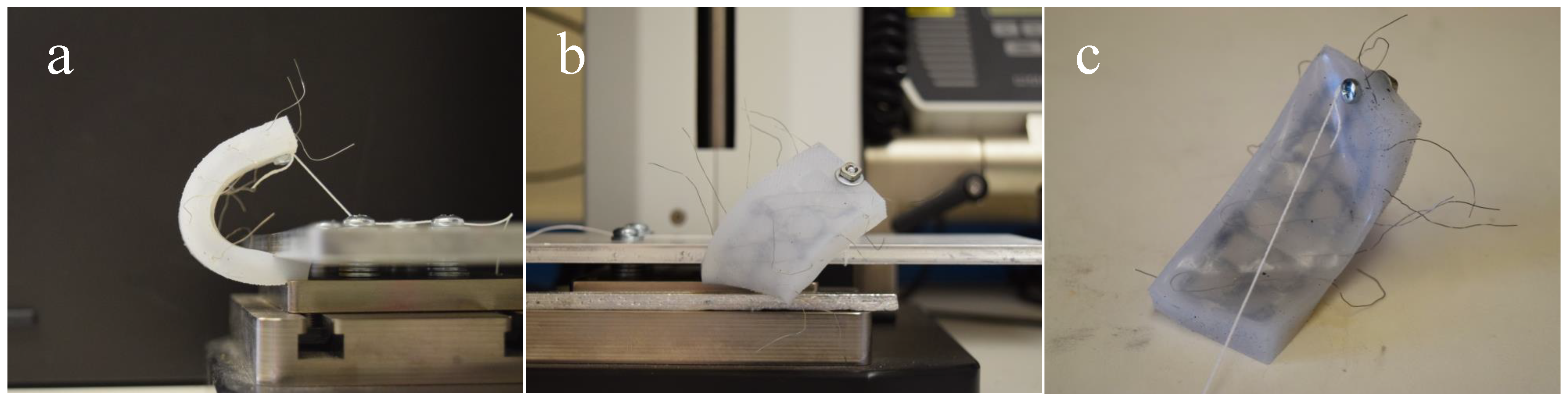
3.1. Verification from Physical Model

The three cases from Figure 1 modeled in MATLAB were tested with the physical lattice to qualitatively verify the theoretical model. Good agreement was found between the physical and theoretical models. As seen in Figure 5, the FM lattice bent along the desired axes when the appropriate segments were melted locally. This behavior supports the hypothesis that the motion of the tip and intermediate points of a robotic element can be described using simple forward kinematics relationships that account for selection of different compliance axes.

3.2. Successive Melting
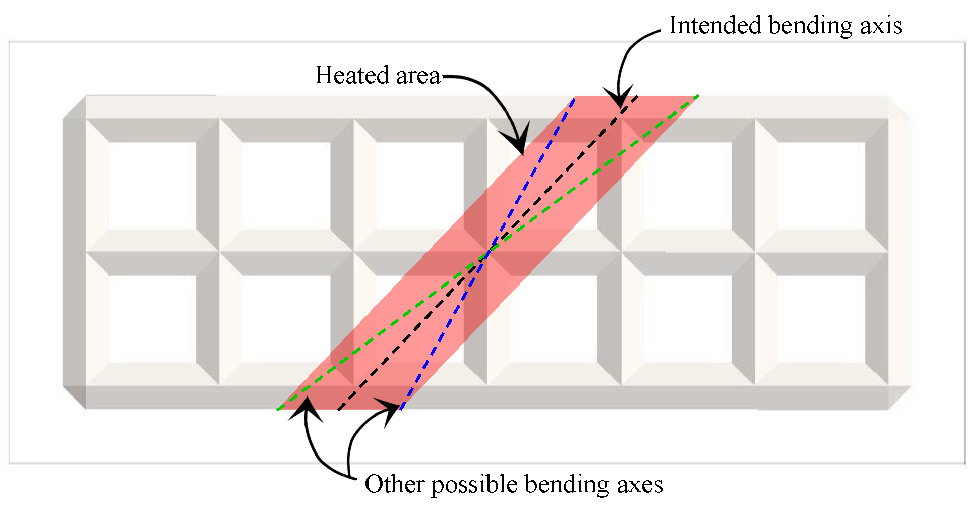
It is interesting to note that if the metal is melted along a particular axis then allowed to solidify in a new shape after bending along the axis, it fundamentally changes the underlying kinematics. A simplified modeling technique for this scenario is to observe that the only thing that has changed from the previous derivation of the kinematics is an additional change to the form of g S i ( 0 ) . As such, the simplified model can be adapted to allow not only changes in the axis of compliance through w i and q i , but through a change in the nominal configurations, g S i ( 0 ) .
This work focuses primarily on the bending motion of the structure as it depends on the selected axis and the input joint angles. Evaluating the relationship between the tendon tension/routing and the resulting joint configurations would rely heavily on the kinematic adaptation of the reference configurations g S i ( 0 ) caused by the successive melting and re solidifying of joints in new configurations. If we are dealing with constant tendon force, greater bending of the lattice is achieved when joints are heated one-at-a-time. However, in the case of this experiment, the displacement of the tendon is held constant rather than the tension, so the bending behavior is not affected by the heating sequence. For this work, the succession of axis melting/bending has no effect on the motion of structure since we are focusing on the relationship between joint axes and angles and the resulting motion/shape of the robotic element.

3.3. Grid Spacing

The grid spacing and width of the heating elements also affect the bending behavior of the lattice. As seen in Figure 2, each heating element melts a certain width of the lattice. When the width of the heated area is small relative to the grid size, more precise control can be achieved. On the other hand, when the width of the heated zone is large relative to the lattice grid size, the orientation of the axes may vary within the heated area. As shown in Figure 6, bending is allowed along any axis contained in the heated zone. This could result in imprecision in the motion of the lattice when the heating elements occupy a wide space. In the future, we hope to make lattices even smaller to enable more dexterous motions; this will require narrower heating elements to avoid diversion from the analytical model. Future work will quantify these effects by measuring deviations from the theoretical model caused by different grid spacings and element widths in the physical model.

4. Discussion

A simple FM lattice encased in a silicone matrix with six heating elements proved capable of bending along nine different axes with the axes of compliance selected/controlled by the heating of localized segments. Whereas previous studies on multi-stiffness materials have investigated controllability of overall material stiffness, this work presents an initial step toward a new realm of stiffness variability where the directionality of the stiffness is controlled in addition to its magnitude.
Applications abound where this increased spatial control could lend itself to advanced robotic manipulation. A new level of dexterity could be attainable through intricate patterning that mimics human tissue in finger-like end effectors. On a larger scale, a thick robotic arm could be capable of both exerting large forces and then collapsing along specified axes to squeeze through tight spaces using a simple temperature stimulus in strategic geometric patterns to trigger a drastic change in physical characteristics.
As more intricate geometric patterns are developed, the challenge of unintentional compliant axes may arise where two or more nearby axes heated simultaneously could result in an additional compliant axis spanning across elements heated by the activated axes. However, strategies can be developed to combat these challenges and avoid compromise of controllability.
Further research will explore the extension of this two-dimensional lattice into three dimensions. Applying 3D patterning of LMP metals to bulk robotic materials could enable highly maneuverable robots that could easily adapt to a constrained environment and perform intricate, intelligent tasks. Predictive models that take into account tendon routing and material properties of the enclosing soft robotics materials will also be explored as well as different mechanisms for locally deforming structures. Future work will provide a comprehensive comparison of quantitative results from experimental testing with the analytical model.

Author Contributions

Conceptualization, J.P.S.; Formal analysis, E.A.A. and J.P.S.; Investigation, E.A.A.; Methodology, J.P.S.; Supervision, J.P.S.; Writing—original draft, E.A.A.; Writing—review & editing, J.P.S.

Funding

This research was funded by the National Science Foundation’s National Robotics Initiative Award 1734117.

Acknowledgments

Special thanks to Lee Taylor for assistance with the fabrication of the test piece.

Conflicts of Interest

The authors declare no conflict of interest. The founding sponsors had no role in the design of the study; in the collection, analyses, or interpretation of data; in the writing of the manuscript, or in the decision to publish the results.

References

  1. Laschi, C.; Mazzolai, B.; Cianchetti, M. Soft robotics: Technologies and systems pushing the boundaries of robot abilities. Sci. Robot. 2016, 1. [Google Scholar] [CrossRef]
  2. Majidi, C. Soft Robotics: A Perspective—Current Trends and Prospects for the Future. Soft Robot. 2014, 1, 5–11. [Google Scholar] [CrossRef]
  3. Yap, H.K.; Yong Ng, H.; Yeow, R.C.H. High-Force Soft Printable Pneumatics for Soft Robotic Applications. Soft Robot. 2016, 3, 144–158. [Google Scholar] [CrossRef]
  4. Yang, G.Z.; Bellingham, J.; Dupont, P.E.; Fischer, P.; Floridi, L.; Full, R.; Jacobstein, N.; Kumar, V.; McNutt, M.; Merrifield, R.; et al. The grand challenges of Science Robotics. Grand Chall. Sci. Robot. 2018, 3, eaar7650. [Google Scholar] [CrossRef]
  5. Kim, S.; Laschi, C.; Trimmer, B. Soft robotics: A bioinspired evolution in robotics. Trends Biotechnol. 2013, 31, 287–294. [Google Scholar] [CrossRef] [PubMed]
  6. Daerden, F.; Lefeber, D. Pneumatic artificial muscles: Actuators for robotics and automation. Eur. J. Mech. Environ. Eng. 2002, 47, 11–21. [Google Scholar]
  7. Trivedi, D.; Rahn, C.; Kier, W.; Walker, I. Soft Robotics: Biological Inspiration, State of the Art, and Future Research. IEEE ICRA 2008, 5, 99–117. [Google Scholar] [Green Version]
  8. Beyl, P.; Van Damme, M.; Van Ham, R.; Vanderborght, B.; Lefeber, D. Pleated Pneumatic Artificial Muscle-Based Actuator System as a Torque Source for Compliant Lower Limb Exoskeletons. IEEE/ASME Trans. Mechatron. 2014, 19, 1046–1056. [Google Scholar] [CrossRef]
  9. Miriyev, A.; Caires, G.; Lipson, H. Functional properties of silicone/ethanol soft-actuator composites. Mater. Des. 2018, 145, 232–242. [Google Scholar] [CrossRef]
  10. Rus, D.; Tolley, M. Design, fabrication and control of soft robots. Nature 2015, 521, 467–475. [Google Scholar] [CrossRef] [PubMed] [Green Version]
  11. Polygerinos, P.; Wang, Z.; Overvelde, J.T.B.; Galloway, K.C.; Wood, R.J.; Bertoldi, K.; Walsh, C.J. Modeling of Soft Fiber-Reinforced Bending Actuators. IEEE Trans. Robot. 2015, 31, 778–789. [Google Scholar] [CrossRef]
  12. Tan, N.; Gu, X.; Ren, H. Design, characterization and applications of a novel soft actuator driven by flexible shafts. Mech. Mach. Theory 2018, 122, 197–218. [Google Scholar] [CrossRef]
  13. Zolfagharian, A.; Kaynak, A.; Khoo, S.Y.; Kouzani, A. Pattern-driven 4D printing. Sens. Actuators A Phys. 2018, 274, 231–243. [Google Scholar] [CrossRef]
  14. Su, J.W.; Tao, X.; Deng, H.; Zhang, C.; Jiang, S.; Lin, Y.; Lin, J. 4D printing of a self-morphing polymer driven by a swellable guest medium. Soft Matter 2018, 14, 765–772. [Google Scholar] [CrossRef] [PubMed]
  15. Schmidt-Nielsen, K. Animal Physiology: Adaptation and Environment; Cambridge University Press: Cambridge, UK, 1997. [Google Scholar]
  16. Koh, J.; Cho, K. Omegabot: Biomimetic inchworm robot using SMA coil actuator and smart composite microstructures (SCM). In Proceedings of the 2009 IEEE International Conference on Robotics and Biomimetics (ROBIO), Guilin, China, 19–23 December 2009; pp. 1154–1159. [Google Scholar]
  17. Margheri, L.; Follador, M.; Cianchetti, M.; Mazzolai, B.; Laschi, C. Bio-inspired Design of an Artificial Muscular-Hydrostat Unit for Soft Robotic Systems. In Proceedings of the Conference on Biomimetic and Biohybrid Systems, Barcelona, Spain, 9–12 July 2012; pp. 375–376. [Google Scholar]
  18. Schubert, T.; Floreano, D. Variable stiffness material based on rigid low-melting-point-alloy microstructures embedded in soft poly(dimethylsiloxane) (PDMS). RSC Adv. 2013, 3, 24671–24679. [Google Scholar] [CrossRef]
  19. Shan, W.; Diller, S.; Tutcuoglu, A.; Majidi, C. Rigidity-tuning conductive elastomer. Smart Mater. Struct. 2015, 24, 065001. [Google Scholar] [CrossRef] [Green Version]
  20. McEvoy, M.; Correll, N. Shape Change Through Programmable Stiffness. In Experimental Robotics; Springer: Cham, Switzerland, 2016; Volume 109, pp. 893–907. [Google Scholar]
  21. Allen, E.; Taylor, L.; Swensen, J. Smart Material Composites for Discrete Stiffness Materials. In Proceedings of the Smart Material Composites for Discrete Stiffness Materials SMASIS, San Antonio, TX, USA, 10–12 September 2018. [Google Scholar]
  22. Gillespie, T.; Best, C.; Killpack, M. Simultaneous position and stiffness control for an inflatable soft robot. In Proceedings of the 2016 IEEE International Conference on Robotics and Automation (ICRA), Stockholm, Sweden, 16–21 May 2016; pp. 1095–1101. [Google Scholar]
  23. Manti, M.; Cacucciolo, V.; Cianchetti, M. Stiffening in soft robotics: A review of the state of the art. IEEE Robot. Autom. Mag. 2016, 23, 93–106. [Google Scholar] [CrossRef]
  24. Magleby, S.; Greenberg, H.; Gong, M.; Howell, L. A Compliant Contact-aided Revolute Joint. Mech. Mach. Theory 2005, 40, 1273–1293. [Google Scholar]
  25. Magleby, S.; Greenberg, H.; Gong, M.; Howell, L. Origami and Compliant Mechanisms. In Proceedings of the Second International Symposium on Compliant Mechanisms, Delft, The Netherlands, 19–20 May 2011. [Google Scholar]
  26. Swensen, J.; Odhner, L.; Araki, B.; Dollar, A. Printing Three-Dimensional Electrical Traces in Additive Manufactured Parts for Injection of Low Melting Temperature Metals. J. Mech. Robot. 2015, 7, 021004. [Google Scholar] [CrossRef]
  27. Murray, R.M.; Li, Z.; Sastry, S.S.; Sastry, S.S. A Mathematical Introduction to Robotic Manipulation; CRC Press: Boca Raton, FL, USA, 1994. [Google Scholar]
  28. Howell, L.L. Compliant Mechanisms; John Wiley & Sons: Hoboken, NJ, USA, 2001. [Google Scholar]
Figure 1. Predicted bending of Field’s metals (FM) lattice achieved by activating different heating elements shown in red. Mathematical model is based on the product of exponentials method of forward kinematics applied to three cases where (a) shows bending along transverse axes w 1 , 3 , w 2 , 3 , and w 3 , 3 ; (b) shows bending along diagonal axes w 1 , 1 , w 2 , 1 , and w 3 , 1 ; and (c) shows bending along w 1 , 2 and w 3 , 1 .
Actuators 07 00080 g001
Figure 2. The fabrication steps for patterned FM test piece, showing (a) FM injected into the 3D-printed soluble mold; (b) FM lattice with soluble mold material dissolved; (c) layout of Nichrome heating elements; and (d) final casting layer of silicone matrix.
Actuators 07 00080 g002
Figure 3. The kinematics of 3-segment lattice where the axes of compliance can be chosen through selective melting. Here the kinematics are developed using a product of exponentials formulation and the axis of rotation is defined by the axis of selective melting for each segment, w i , p . These potential axes of compliance are shown for each segment in red, green, and blue.
Actuators 07 00080 g003
Figure 4. Development of forward kinematics matrices for specific example case where compliance axes ω 1 , 3 , ω 2 , 3 , and ω 3 , 3 are selected, allowing bending along the three transverse axes.
Actuators 07 00080 g004
Figure 5. Bending achieved by FM test piece showing (a) bending along transverse axes w 1 , 3 , w 2 , 3 , and w 3 , 3 ; (b) bending along diagonal axes w 1 , 1 , w 2 , 1 , and w 3 , 1 ; and (c) bending along w 1 , 2 and w 3 , 1 .
Actuators 07 00080 g005
Figure 6. Effects of grid spacing and heating element width on bending axis precision. For this particular heated zone, bending is allowed along any axis between the green and blue axes. This could cause discrepancy between experimental and theoretical results if the analytical model is based on the intended bending axis but actual bending occurs about a different axis within the heated zone.
Actuators 07 00080 g006

