A Vacuum Powered Soft Textile-Based Clutch


Center for MicroBioRobotics, Istituto Italiano di Tecnologia (IIT), 56025 Pontedera, Pisa, Italy
*
Authors to whom correspondence should be addressed.
Actuators 2019, 8(2), 47; https://doi.org/10.3390/act8020047
Submission received: 25 March 2019
/
Revised: 30 May 2019
/
Accepted: 2 June 2019
/
Published: 6 June 2019
(This article belongs to the Special Issue New Materials and Designs for Soft Actuators)
Abstract
:We present the design, manufacturing, and characterization of a soft textile-based clutch (TBC) that uses vacuum stimulation to switch between locking and unlocking its linear displacement. The vacuum locks the relative sliding motion between two elaborated textile webbings with an elastic silicone rubber bag. Various fabrication techniques, such as silicone casting on textiles and melt embossing for direct fabrication of miniature patterns on textile and sewing, were used to develop three groups of TBC samples based on friction and interlocking principles. Their performance was compared in a blocking configuration. The clutch with an interlocking mechanism presented the highest withstanding force (150 N) compared to that (54 N) recorded for the friction-based clutch. The simple and compact structure of the proposed clutch, together with the intrinsic adaptability of fabric with other clothing and soft materials, make it an appropriate solution for applications in soft wearable robotics and generally as a locking and variable stiffness solution for soft robotic applications.
1. Introduction
Clutches are locking devices that are widely used in robotic systems. They switch between enabling and preventing the relative motion of two parts, above all for energy management, reconfiguration, and safety reasons. In addition to the conventional use of clutches for engaging and disengaging the driven components from the driving source, they are also used to lock and unlock robot motions and facilitate reconfiguration [1]. For example, in modular and reconfigurable robots, the use of clutches reduces the number of actuators and consequently results in lighter weight modules [2,3]. Similarly, in underactuated systems, the use of clutches enables high degrees of configurability to be achieved with a low number of actuators [4]. Using clutches as an essential component for decoupling from actuators and impedance control enables robots with rigid arms to achieve softer and safer interactions with the environment [5].
In many robotic designs, clutches are powerful components for the storage and fast release of elastic energy for various purposes, such as jumping in mobile [6,7] and legged robots [8]. In unpowered and quasi-passive exoskeletons, clutches play a key role in storing elastic energy, which permits force development with a low or zero energy cost in assisting the wearer (e.g., patient) during walking [9,10,11].
Underactuated exoskeletons often integrate conventional rigid clutches for the direct freezing and control of the wearer’s joints without the use of actuators, such as electromagnetic [12,13], electrostatic [11], magnetorheological fluid-based [14], or electrorheological fluid-based [15] clutches.
There are several promising examples of soft exosuits that aim to bring comfort and higher adaptability to the wearer’s body using intrinsically soft and light structural materials (e.g., textiles and soft elastomers) and soft actuation technologies [16]. However, most of the unpowered soft exosuits still include clutching systems based on rigid, bulky, and heavy conventional clutches [17]. An example of a flexible clutch, based on electro-static force for quasi-passive ankle-foot orthosis exoskeletons, is presented in Reference [11]. However, the need for rigid and planar connection plates at each end in order to ensure the parallel gap between electrodes still entails rigidity. Moreover, the use of a high voltage for wearable devices can involve safety problems.
To address wearability, comfort, and safety issues, in this paper we propose an entirely soft textile-based clutch actuated by vacuum sources with unconventional load capabilities.
Vacuums are exploited in several soft robotic technologies for two main areas of applications: Actuation [18,19,20] and variable stiffness solutions [21,22]. The successful use of a vacuum in a granular jamming-based universal gripper [21] has motivated many other researchers to exploit a similar approach to tune the stiffness in soft structures for many applications, such as medical [23] and adaptive grasping [24]. Variable stiffness sleeves based on the jamming mechanism of rubbery granules under vacuum are proposed in Reference [22] for stiffening wearer body joints in a soft exoskeleton. Similarly, in the layer-jamming mechanism, the vacuum power pushes the internal layers of a soft multi-layer structure together and converts it into a relatively stiff body. This clutch-like solution is also exploited in several fields, such as medical [25] and wearable robotics [26,27,28,29]. Although both the granular and layer jamming mechanisms have demonstrated promising variations of stiffness for various soft robotic applications, increasing the final stiffness of a structure by only changing the amount of granules or layers results in bulky and heavy structures with a higher stiffness, not only in the active but also in the passive mode.
In this work, we detail the design and development of a new soft robotic component, which is a textile-based clutch (TBC) that exploits vacuums as the activation solution. The TBC is a highly compliant, lightweight, compact, and soft clutch created with low-cost components: textiles, plastics, and silicone. We chose textiles as a base material for the creation of our TBC due to their high level of softness and adaptability with wearable technologies, combined with easy integration with other materials commonly used in soft robotic structures (e.g., silicone elastomers). Aimed at improving the blocking capabilities of TBC, the surface of the textile layers has integrated miniature plastic structures that interlock with each other.
A comparison with other solutions based on high friction materials (to improve the blocking force) is also performed, demonstrating the effectiveness of our solution. Activation strategies are also analyzed to improve the response time of TBC.
2. Materials and Methods
2.1. Textile-Based Clutch
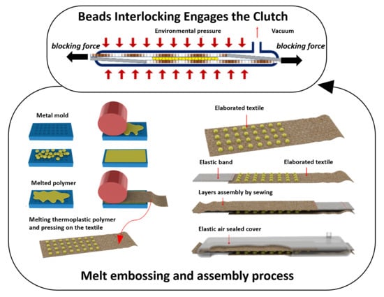
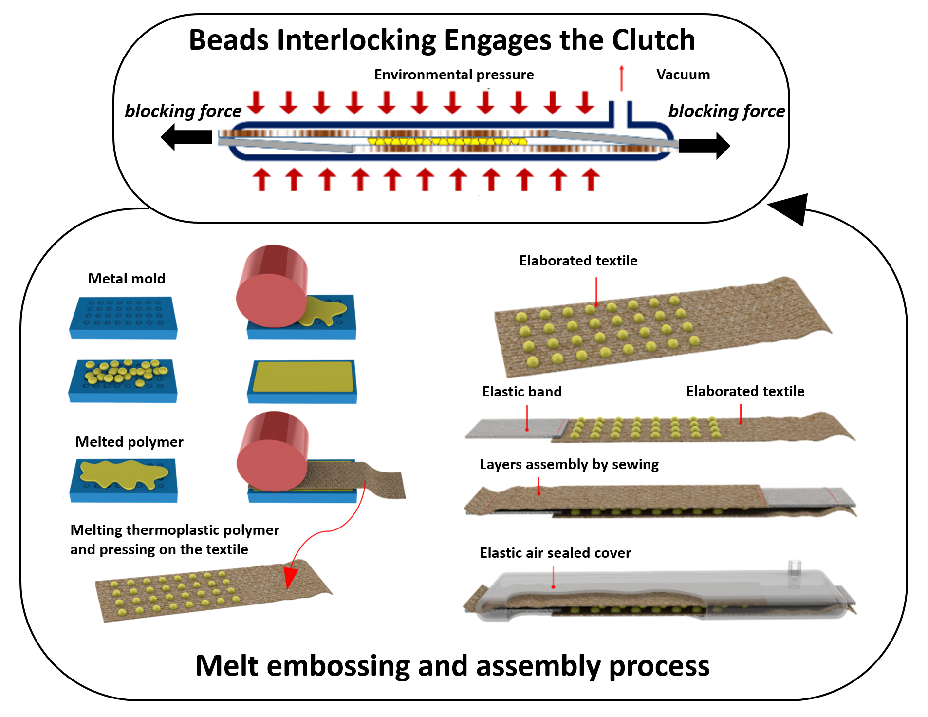
The soft TBC presented in this work is a bilayered elastic belt whose elongation can be blocked by applying negative pressure (i.e., via a vacuum). The TBC comprises two elaborated inextensible textile—woven cotton—webbings, both in series with an elastic textile band. The two layers are connected together: The head of each inextensible textile is fixed to the head of the elastic band in the other series. Finally, the bilayer assembly of textile bands is packed inside a flat and air-sealed elastic cover that enables the device to be easily elongated (Figure 1a). In the passive mode (Figure 1b,c), the two TBC layers can freely slide in front of each other and consequently the TBC elongates with a minimum force, which, based on Equation (1), depends on the elasticity of the cover, elastic bands, and frictional interaction between layers. The application of a negative pressure inside the elastic cover activates the TBC (engaging mode) and creates a temporary adhesion between the textile layers (Figure 1d). The flexibility of the elastic cover thus means that the external environmental pressure squeezes the cover and pushes the inextensible textile webbings towards each other leading to a temporary and strong adhesion (Figure 1d). The interfacing zone where the surfaces of elaborated inextensible textile webbings meet (Figure 1b) plays a key role in the adhesion strength during the engaging mode.
Equation (2) shows how the magnitude of the engaging force (Fengaing) is a function of the applied negative pressure (ΔP) and the characteristics of the device, such as the area occupied by the elastic bands Ael, area of the interfacing zone Ain, the coefficient of friction between the textile layer and elastic bands µtex, and the effect of elaboration technique (µelaboration).
The elongation ratio (ERTBC) is the clutch elongation divided by the clutch length (lTBC). In line with the design in Figure 1b, lTBC can be expressed as a function of the length of the interfacing zone (liz) and the length of the elastic bands (le) (Equation (3)). The maximum elongation is physically limited by the elongation ratio of the elastic bands (ERe), but in practical terms, for elongations greater than liz, the device cannot ensure an effective engaging force, and in this situation, the interlocking of the elaborated parts is not guaranteed. The ERe and ERTBC conditions that block the TBC for each elongation are defined in Equation (4). The TBC can elongate until the maximum elongation in the elastics occurs. Elongations greater than this limit can permanently damage the elastics and cause the device to malfunction. However, depending on the application of the TBC, a longer elastic band can be selected where a longer elongation range or lower elongation force during the disengaging mode is required.
Another important parameter of the TBC is the withstanding force in the active mode. This force can be modified by elaborating the frictional properties at the interfacing zone. Using materials with a high coefficient of friction (e.g., rubber coating) on the surface of the inextensible textile can improve how well the TBC engages without influencing the flexibility of the device.
We used small and rigid segments (called bumps) integrated onto the surface of inextensible textiles in order to mechanically interlock the two textile layers to improve the withstanding force. This solution improves the clutching performance by adding the force of mechanical interlocking to the frictional based force of engaging alone.
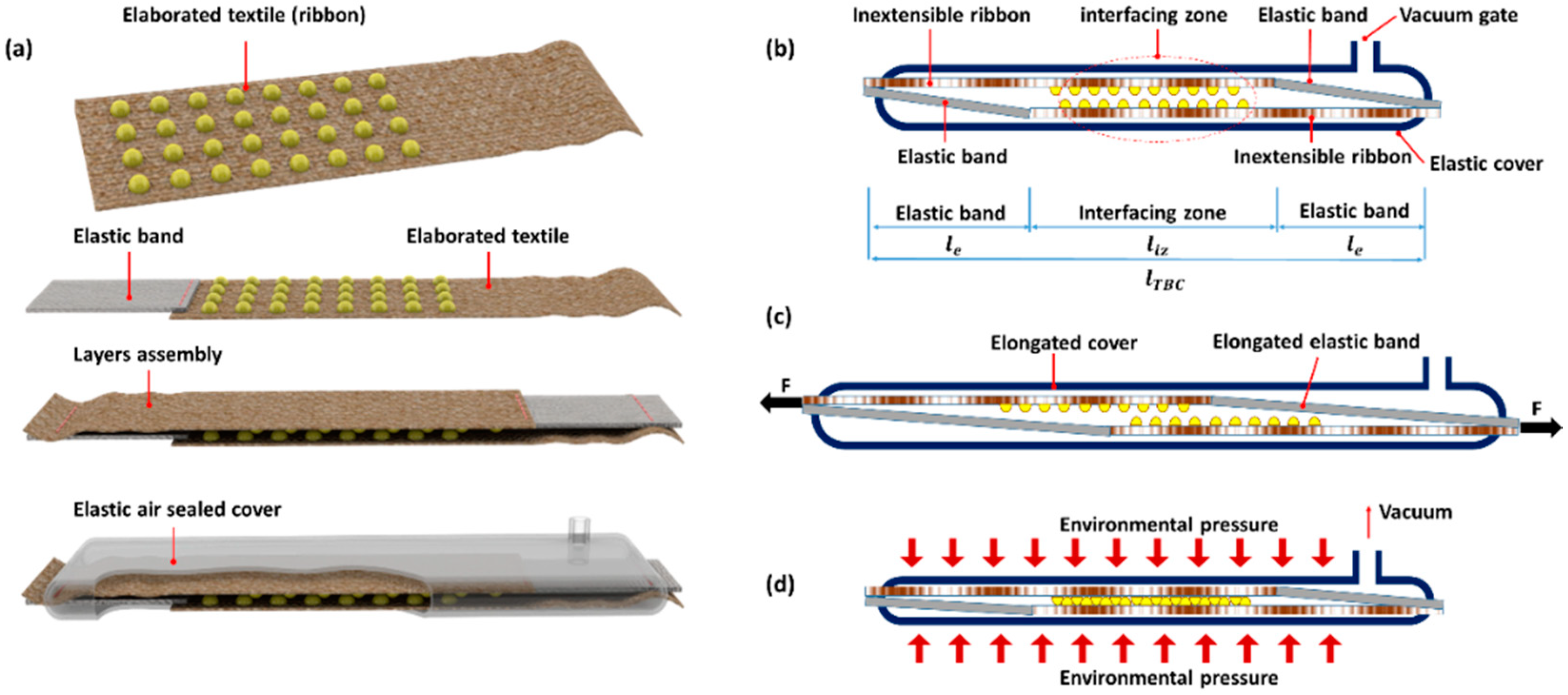
Similarly to the teeth in a dog clutch [30], the rigid bumps on each of the textile webbings can enter the free space between the bumps on the other webbing, leading to an interlocking action used to prevent the TBC from elongating (Figure 1). Elaboration of the webbings by this technique does not interfere with their flexibility as the bumps are integrated in an array format (Figure 2a). In fact, the area occupied by the rigid bumps in the array is small and the textile in the gap between the segments remains flexible (Figure 2b and Supplementary Materials, Video S1).
Both the geometry and frictional property of the bumps can influence the result of the interlocking action during the engaging mode. In this work we selected a semispherical geometry for the bumps. During the disengage mode, bumps with a semispherical shape easily slide on top of each other and do not significantly affect the elongation force (Supplementary Materials, Video S2). In the engaging mode (vacuum applied), each single bump is subjected to a normal force generated by the pressure. This bump penetrates the front array of bumps, creating an engaging action that prevents the bumps from sliding on top of each other (Supplementary Materials, Video S3). In an array of semispherical interlocking bumps when all the bumps have penetrated each other, by assuming that the array of bumps remains planar and the bumps remain perpendicular with respect to the array plane, the interlocking force can be obtained by Equation (5). Supplementary Material S4 gives the details of Equations (5) and (6).
Equations (5) and (6) reveal that the withstanding force can be affected by the size of the bumps (r, the radius of semi-spheres), the number of bumps in array (n × m), their distance (d), and their frictional properties (µ), together with the size of the elastic zone (Aelastic) and its frictional properties (µez). Larger bumps can generate a larger normal force caused by environmental pressure during the vacuum. This results in a larger withstanding force, which is also influenced by the number of bumps (Figure 2). According to Equation (6), the shorter the distance d is, the larger the engaging force. The x in this equation is the distance between the contact point of the interlocked bumps and the center of each bump. The distance of the bumps should also satisfy the condition in Equation (7), otherwise no interlocking between bumps of two arrays is guaranteed.
A tradeoff for the size of the bumps is required, as the larger bumps can transform the environmental pressure to a higher normal force, while smaller bumps enable a higher number of bumps to be integrated. The influence of size and density of bumps were investigated in our prototypes and experimental studies, and are reported in the next sections.
2.2. Prototyping
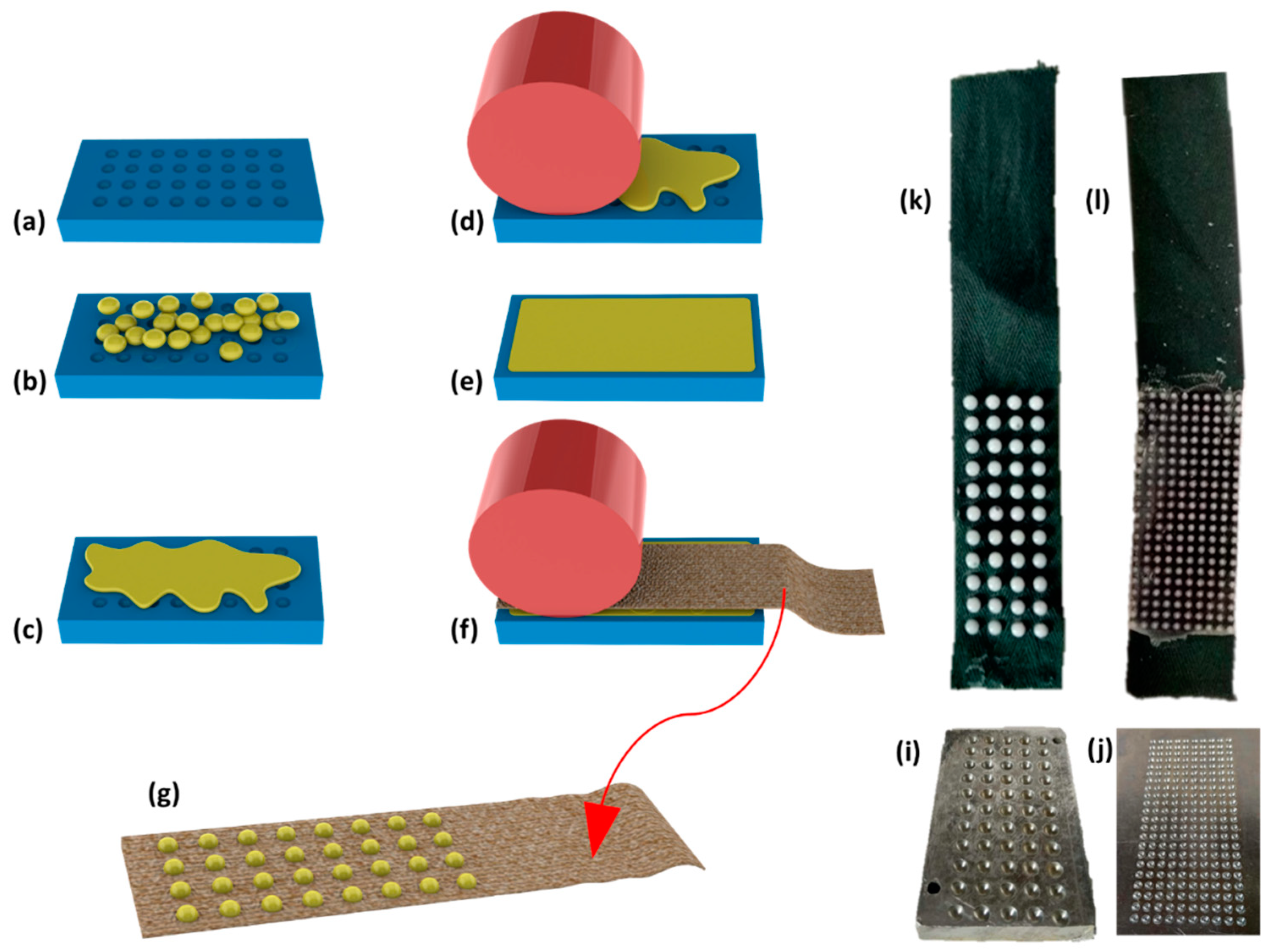
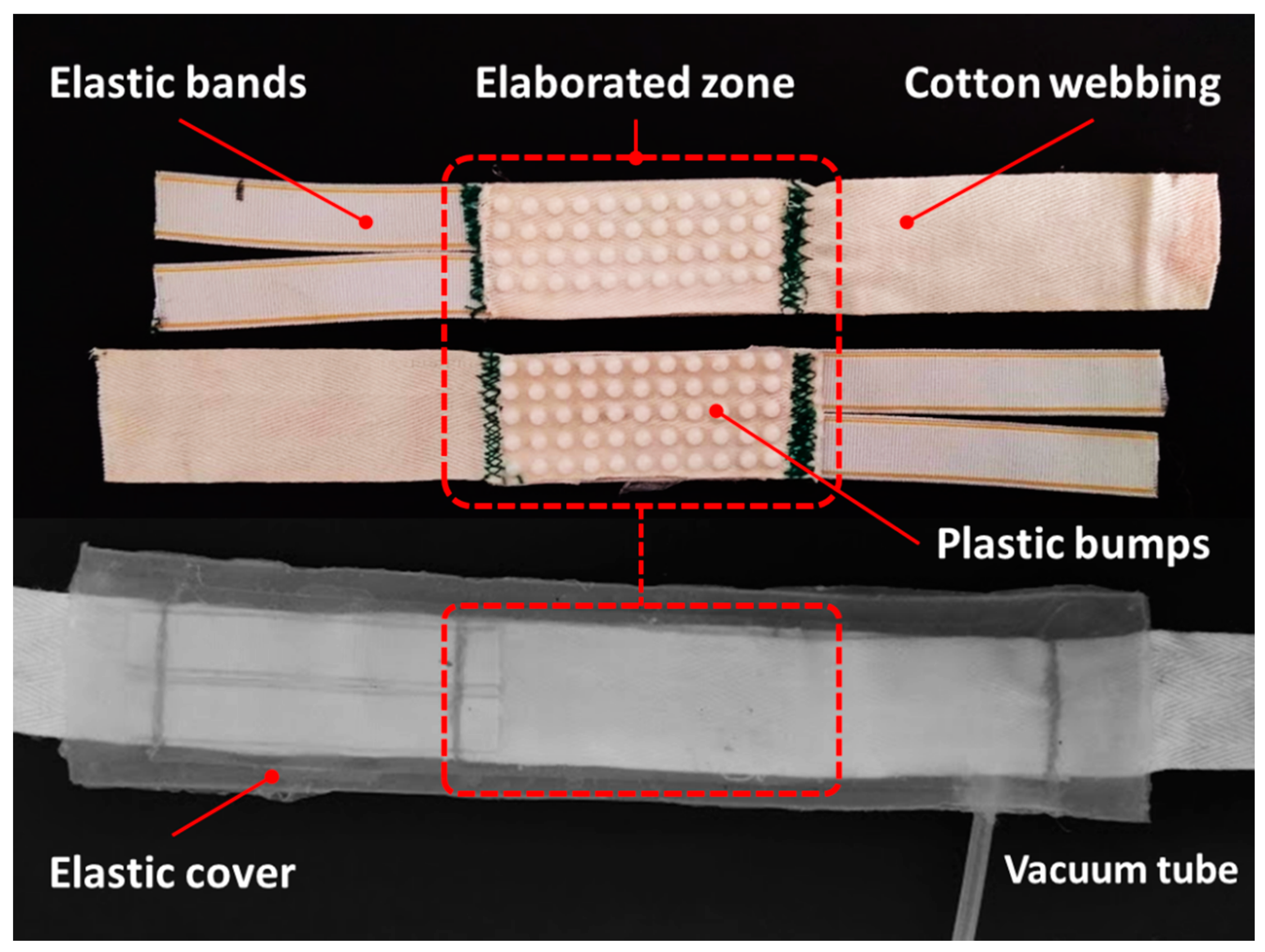
We combined different techniques such as embossing, casting, and sewing to develop the TBC prototypes (Figure 3a–g). For each clutch, the array of rigid bumps was directly fabricated on a pair of woven cotton webbings (0.5 mm thickness and 30 mm width). Two series of TBC prototypes with 4 mm and 2 mm diameter semispherical bumps were made. The bumps were directly shaped and integrated on the textile webbings by CNC milled aluminum molds (Figure 3i,j). The metallic molds enable the array of bumps to be made quickly and accurately in one shot of pressing action. The granules of polyoxymethylen (POM) thermoplastic with high stiffness and excellent dimensional stability [31] were first poured into the preheated (270 °C) aluminum mold (Figure 3a,b). After fusing granules, they were pressed inside the mold’s semispherical cavities by rolling a metallic cylinder over the fused materials until a thin, flat, and homogenous layer was obtained (Figure 3c–e and Supplementary Materials, Video S1). The bumps inside the aluminum mold were transferred to the cotton webbing by locating the webbing on the top of the array and pressing it towards the melted polymer, again by rolling the metallic cylinder (Figure 3f). By pressing, the melted thermoplastic penetrates the textile porous texture and creates a strong bonding which is unified by the bump material. Finally, the assembly was removed from the mold after cooling the mold with cold water (Figure 3g). The strong bonding of the bumps to the textile guarantees the stability of the bumps in their location under shear forces generated during the engaging action. TBCs with 4 mm bumps integrate arrays of 5 × 11 bumps in front of 4 × 11 with a 6 mm distance between bumps (Figure 3k); TBCs with 2 mm bumps were made from arrays of 10 × 22 in front of 9 × 22 with a distance of 3 mm in between bumps (Figure 3l). The webbings with one column less of bumps permit a symmetric configuration of webbings in the final assembly as the bumps of each webbing sit in the free space between bumps of the other webbing. An elastic textile band with 15 mm width and maximum 120% elongation (Super-Elastic Prym Co., Stolberg, Germany) was sewn to one head of each elaborated webbing. Sewing was selected as it is one of the best techniques that adapts to the textile without affecting its properties or generating any rigidity in the connection point of the elastic and non-elastic bands while providing a strong bonding. The total practical length of all the TBC prototypes was 180 mm, while the length of the interfacing area was 60 mm. For all the prototypes, an elastic cover larger than the textile assembly was created by a casting process of silicone elastomer (Ecoflex 0030 of Smooth-On Co., Macungie, PA, USA) with a rectangular shape (50 mm × 220 mm, with 1 mm of wall thickness). The whole assembly of textile bands was inserted and sealed inside the elastic covers (Figure 4). A 4 mm silicone tube (SAINT-GOBAIN Co., Courbevoie, France) was later integrated to the elastic cover by silicone caulk.
Two other series of clutches based just on frictional materials were created in order to compare the results with the TBC prototypes based on interlocking. Their interfacing zones were elaborated with a high coefficient of friction materials: One by adhering sandpaper (P600) on the top and bottom sides of the interfacing zone; the second by coating 0.5 mm of silicone rubber at the interfacing zone, which was achieved by the direct sinking of textile webbing in silicone elastomer (Ecoflex 0030, Smooth-On, Inc.).
2.3. Clutch Control Unit
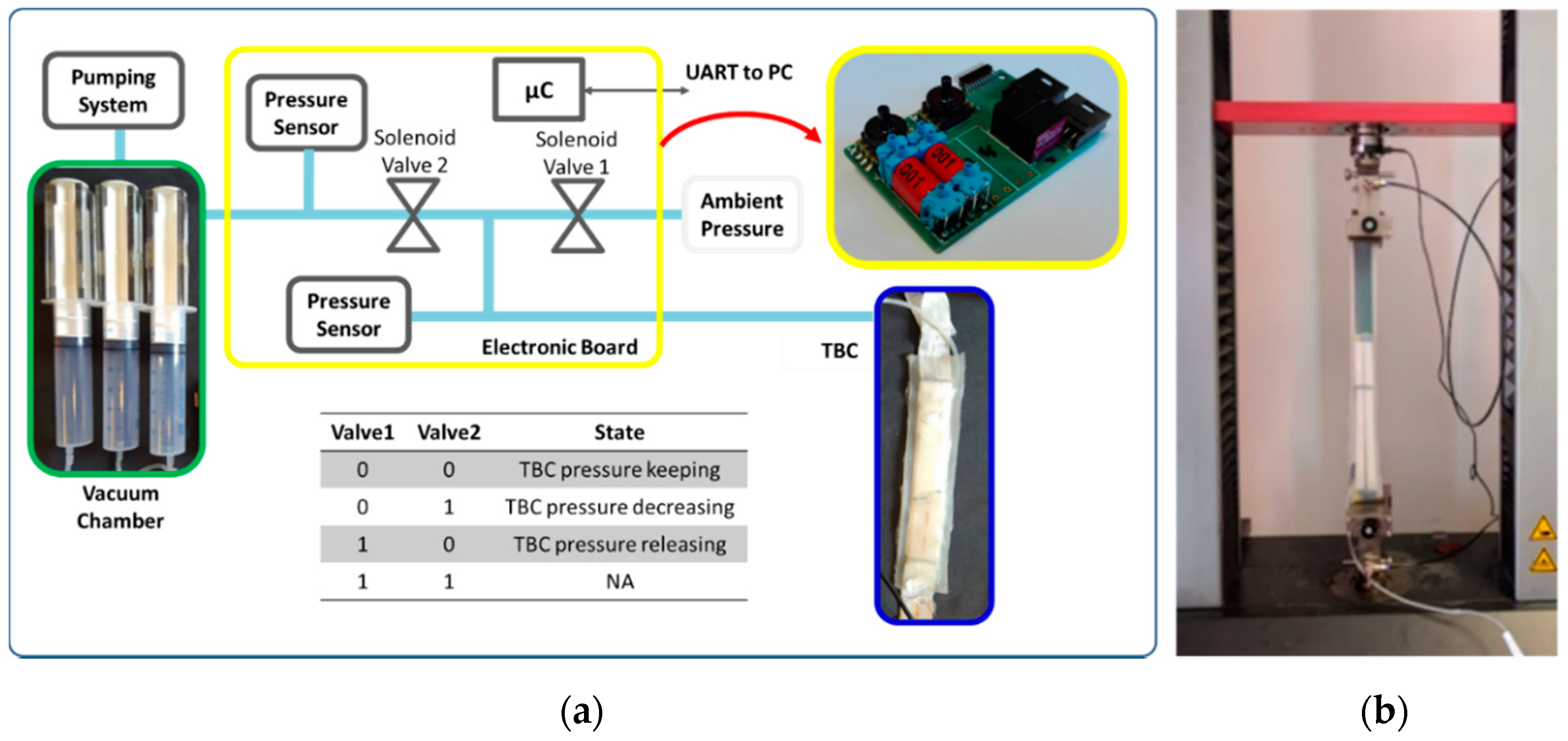
In order to address the requirements of compactness and mobility in wearable devices, we developed a miniature pneumatic circuit that is managed by a custom control unit. A microcontroller (TMS320F28035 from Texas Instruments, Dallas, TX, USA) regulates the pressure inside the TBC through two pneumatic valves (TX3P030LV03LN from First Sensor AG, Berlin, Germany) and a pressure sensor (MPXV6115V from NXP Semiconductor, Eindhoven, The Netherlands). One of the two valves (valve 1 in Figure 5) connects the clutch to the ambient pressure for the disengaging mode, while the other valve (valve 2) connects the clutch to a vacuum chamber for the engaging mode. A second pressure sensor is located between valve 2 and the vacuum chamber to monitor the pressure of the chamber. A PC is connected to the setup by a serial interface (UART) to set the clutch pressure and acquire the pressure monitored by the system. A control loop is implemented in the microcontroller to maintain the set pressure. Normally, both valves are deactivated; in this condition the clutch is closed and the pressure inside is kept to the reached value. We added a hysteresis of ±0.01 bar to the set value to prevent any unnecessary valve activation and waste of energy. We used a vacuum chamber as the vacuum reservoir that decouples the pump speed from the actuator speed. The vacuum chamber is brought to the desired vacuum level by the pumping system and then switched off. The developed system was used to characterize the clutch in terms of force and response time. In a real application, a constant pressure inside the reservoir can be guaranteed by the same control unit and by monitoring the pressure sensor between valve 2 and the reservoir.
2.4. Experimental Protocols and Setups
Two sets of experiments were performed on the TBC prototypes to characterize their withstanding force under different conditions and their response time during engaging and disengaging. The force-elongation tests were performed by a material testing machine (Zwick/Roell Z005) and the pneumatic circuit discussed in the previous section to set the pressures in the TBCs (Figure 5b). We evaluated the engaging forces of all the TBC prototypes (friction based and interlocking based) under different negative pressures: 0 atm (no vacuum) to −0.8 atm with 0.2 atm steps, for 25 mm elongation with 100 mm/min linear velocity. The tests with no vacuum pressure (0 atm) were performed to measure the minimum force required for the elongation of TBCs in the passive mode.
In order to clarify the frictional effect of the elaboration solutions on the minimum elongation force and differentiate it from the effect of the elastic bands and the elastic covers, the elongation force of the elastic cover and elastic bands were also characterized separately. The experiments were repeated five times for three samples of each prototype. The response times of the interlocking TBC clutches for both engaging and disengaging actions can be affected by several factors such as the size of the TBC clutches, the volume and pressure level of the vacuum chamber, the valve dimension, length and size of the pneumatic circuit, and the desired final pressure level for the TBC.
We evaluated the TBC speeds with the same compact and portable control unit, considering that one of the main applications of the clutch would be in soft exosuits where compactness, low weight, and wearability are required. These measurements were taken by evaluating the rate of the pressure variation inside TBC during its activation. In order to investigate the influence of the reservoir capacity on the response time of TBCs, the experiments were repeated for three different sizes of vacuum reservoirs (50 mL, 100 mL, and 150 mL) at maximum negative pressure (−0.8 atm).
In these tests, when the desired vacuum was achieved, the vacuum pump was disconnected from the chamber to exclude the performance of the pump from the reservoir effect. The disengaging response time was evaluated by connecting the TBCs to a constant pressure of −0.8 atm (as maximum achieved negative pressure) and by measuring the time needed to reach the ambient pressure once valve 1 was open. To accelerate the response of the TBCs with soft inflatable silicone covers, we hypothesized that pre-charging the device with a small negative pressure during the disengaging mode could reduce the device’s internal volume by deflating the cover and consequently reducing the engaging response time, while the small negative pressure did not significantly influence the minimum elongation force in this mode. We experimentally evaluated this technique by applying small vacuum values while measuring the minimum elongation forces. Based on this experiment, we later evaluated the response time of the TBCs when they were pre-charged by this negative pressure. All the experiments were repeated five times for each testing condition.
3. Results and Discussion
In the tests at ambient pressure (0 atm), all the devices demonstrated a similar elongation force of 14.9 N, 15.7 N, 14.4 N, and 15.1 N, respectively, for small bumps, large bumps, sand paper, and silicone rubber coating. Comparing these measures with the elongation force of just the elastic bands together with the elastic cover (14 N), we observed that most of the elongation force during disengaging mode is due to the properties of the elastic elements instead of the effect of the frictional properties of the elaborated techniques.
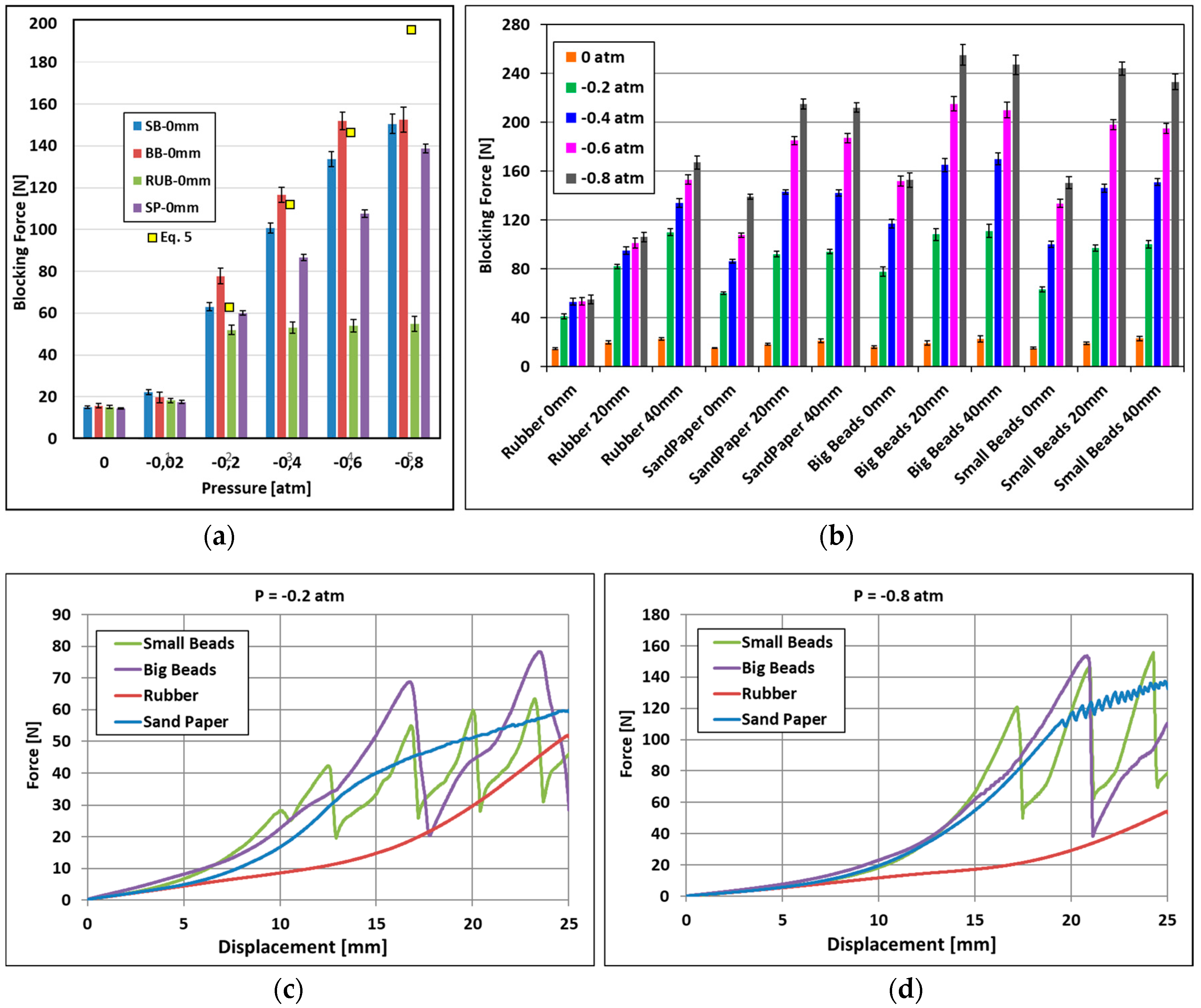
All the negative pressures tested were able to block the elongation of the interlocking TBC with different withstanding forces. As expected, the highest maximum force was obtained with the TBCs elaborated by the interlocking bumps. Both of the interlocking prototypes with small and large bumps showed a better performance than the friction-based TBCs (Figure 6a). The average maximum withstanding force of the small and large bump interlocking TBCs were 150.5 N, and 152.6 N, respectively, in relation to −0.8 atm for 25 mm elongation of the TBC. In these prototypes the number of bumps (m × n) multiplied by the area of each bump (πr2) is almost the same. This explains (Equation (5)) why a big difference in withstanding force between them was not found. The small differences in these measurements could be due to the fact that the silicone cover does not fit well in the small gaps in between the small bumps, in comparison with the larger gaps in between the bigger bumps.
In order to validate the proposed model for the blocking force (Equation (5)), we characterized the frictional properties of POM on POM (µ = 0.19). We also measured the variable coefficient of friction between the elastic bands on the textile (µez = 0.5, 0.41, 0.32, and 0.32) in relation to the different pressures applied (0.2 atm, 0.4 atm, 0.6 atm, and 0.8atm). We used these frictional values and the dimensional measures of both the small and large bump prototypes for different working pressures. The results of the equation are plotted in Figure 6a.
Except for the highest pressure (0.8 atm), we observed a low deviation (up to 3%) between the measured and calculated forces. In the case of the highest pressure (0.8 atm), the experimental forces were almost 30% lower than the calculated force. We believe that under the high-exerted forces, the flexibility of the textile enables the bumps to bend in their location and to reduce their interlocking performance. Using materials with a lower flexibility than textiles would help to obtain results closer to the analytical predictions. Nevertheless, the model still helps in approximating the withstanding force for the parameters of the device.
Based on our experimental results and prototyping experiments, the smaller size of the bumps results in softer and more compact TBCs. However, molding smaller features is generally more complicated and bump adhesion with textiles is less reliable. On the other hand, bigger beads result in a thicker device and are stiffer in the passive mode.
We also observed an unexpected behavior between 0 mm and 20 mm in all the TBC prototypes: The blocking force increases even when the overlapping area in the interlocking zone decreases (Figure 6b). This behavior is due to the adaptation of the elastic cover along the sides of the elongated textile (over bumps) and increases the overall length of the clutch under the negative pressure (vacuum). The maximum forces measured for the TBC samples with sand paper and silicone coating were 138.7 N and 54.8 N under the same negative pressure (−0.8 atm).
At the beginning of each blocking test, we observed a 12–15 mm extension of the textile webbings and therefore the first time that engaging was interrupted was after this initial stretch of the textile. The force-displacement graphs of interlocking TBCs (Figure 6c,d) demonstrate the locking action of these types of clutches in the smallest vacuum pressure (−0.2 atm) and biggest vacuum pressure (−0.8 atm). The peaks in these graphs relate to the moment when the interlocking action of the clutch fails, and the bumps slide on top of each other and again sit inside the gap between them and the device recovers its locking action. For this reason, the distance between the peaks of the graphs corresponds to the distance of bumps in the array of each prototype, which is 3 mm for the array with small bumps and 6 mm for the array with larger bumps.
Even after breaking the withstanding force, all the TBCs continue to elongate with an increasing force, which is due to the effect of the elastic elements (elastic bands and elastic cover) as well as to an enlargement of the TBC area during elongation, which results in a larger normal force generated by environmental pressure. Similarly, the action of the TBCs elaborated by sand paper was visible when the elongation of the inextensible textile was stopped. This clutch, after its first breaking, engaged and disengaged with very small peaks in the force-displacement graph affected by miniature bumps of sand paper roughness. However, with the interlocking TBCs and sand paper, the TBCs elaborated by silicone rubber without any clear breaking moment demonstrated a growing force the cotton webbing was no longer extending. This clutch demonstrated a lower withstanding force with less sensitivity to the variation in pressure compared to the other TBC prototypes. However, the maximum measured force was much higher than the minimum measured force (disengaging mode) in ambient pressure.
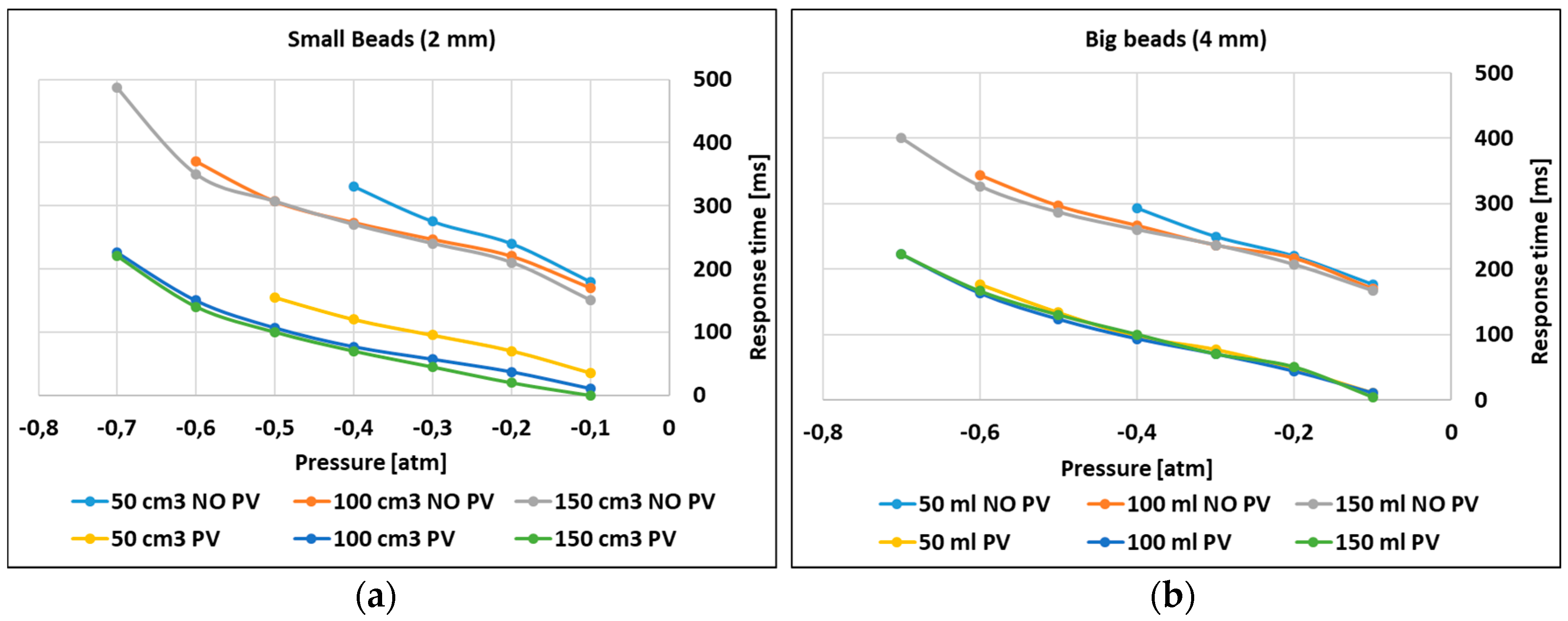
The results of the TBC response time with small and rigid bumps and in engaging mode from environmental pressure to the different target pressures are shown in Figure 7a. We measured a slightly faster response time in the case of reservoirs with a bigger volume. The TBC with the bigger bumps was also generally faster than the TBC with the smaller bumps, probably because the elastic cover adapts more easily to the large gap between large bumps (Figure 7b).
The use of larger reservoirs led to a higher negative pressure inside the TBCs. In the case of applications that require high withstanding forces and consequently higher pressures, a larger reservoir would therefore be a good selection. We also recorded a faster response time in the experiments where TBCs were pre-vacuumed (internal pressure was set to −0.01 atm). The target pressure in the case of pre-vacuum was generally 160 ms faster. For example, in the test with the slowest speed, the TBC with large bumps took 350 ms to reach −0.6 atm, while the same pressure was achieved in 160 ms in the case of pre-vacuum (190 ms faster).
In general, the average response time of TBCs with small and large bumps varied between 170–370 ms and 170–343 ms, respectively, in the normal case, while after setting a pre-vacuum inside the clutches, this range decreased to 3.3–226 ms and 10–223 ms to reach −0.7 atm (with the chamber of 100 mL). This is when the elongation force does not show a significant difference between the −0.01 atm (19–20 N) and 0 atm (15–16 N) conditions. In addition to the TBC performance, all these results were also influenced by the performance of the fluidic system (e.g., valves, tubes).
In terms of the disengaging mode, we recorded an average response time of 200 ms and 210 ms for the TBCs with small and large bumps, respectively. The discharge response time was also faster after blowing air inside the clutch, which assisted the disengaging phase by positive pressure.
4. Conclusions
We have presented a flat, compact, and powerful soft clutching device that exploits the intrinsic flexibility of textiles and silicone elastomers. The device simulates the functionality of conventional clutches and breaks in its soft-bodied structure and it is also able to conform and adapt to different shapes.
Two main series of textile-based clutches (TBCs) were developed and characterized based on the interlocking of miniature patterns on the textile, and friction between the coatings of sand paper and silicone rubber on the textile. Our TBCs presented a maximum withstanding force of 152 N, which was obtained using two layers of textile. The TBCs also demonstrated a high withstanding-weight ratio of 340 times, considering the average weight of 45 g for all the prototypes developed.
The small size of the TBC results in a low internal volume with a consequent relatively fast response time (in the order of 200 ms) even with a small and lightweight vacuum system.
The novel concept of interlocking and the direct fabrication of plastic beads on the TBC layers results in considerably higher withstanding forces than with other multi-layer jamming works reported in the literature, i.e., 17.5 N for each layer in Reference [27] and less than 10 N in Reference [29]. In addition, the use of elastic bands in series with textile webbings guarantees a high elongation ratio of the TBC without the risk of buckling and wrinkling, which is a common problem in the layers of soft materials.
The high elongation ratio of the proposed device (up to 33%) and the relatively fast response time of the clutches expand its possible application to many different fields, such as wearable robotics. For example, the TBC clutches can be integrated into a soft exosuit to limit and control the joint motions for assistive and rehabilitation applications [32]. In such applications, the flat configuration and softness of the developed clutch permit a high adaptability to the wearer’s body and ease of integration to textile based garments.
The combination of this device in parallel or series with other elastic elements also facilitates engaging and disengaging or bypassing elastic elements in robotic structures. This could lead to many applications in impedance control scenarios in legged robots and in unpowered exoskeletons and exosuits. The compact size of each TBC means that several TBCs can be configured in parallel in a compact or flat assembly, which results in greater withstanding forces when loads higher than a single TBC are required. As a future work we also aim to investigate the effects of different bump shapes and patterns on the performance of TBCs.
Supplementary Materials
The following are available online at https://www.mdpi.com/2076-0825/8/2/47/s1, Video S1: Clutch Fabrication, Video S2: TBC passive mode, Video S3: TBC weight lifting, S4: Withstanding Forces.
Author Contributions
Conceptualization, A.S.; methodology, A.S., A.M.; validation, A.S., A.M.; writing—original draft, A.S.; writing—review and editing, A.S., A.M., B.M.
Funding
This work has received funding from the European Union’s Horizon 2020 framework programme for research and innovation under grant agreement No. 688175.
Conflicts of Interest
The authors declare no conflict of interest.
References
- Plooij, M.; Mathijssen, G.; Cherelle, P.; Lefeber, D.; Vanderborght, B. Lock your robot: A review of locking devices in robotics. IEEE Robot. Autom. Mag. 2015, 22, 106–117. [Google Scholar] [CrossRef]
- Karbasi, H.; Huissoon, J.P.; Khajepour, A. Uni-drive modular robots: Theory, design, and experiments. Mech. Mach. Theory 2004, 39, 183–200. [Google Scholar] [CrossRef]
- Murata, S.; Kurokawa, H.; Yoshida, E.; Tomita, K.; Kokaji, S. A 3-D self-reconfigurable structure. In Proceedings of the 1998 IEEE International Conference onRobotics and Automation, Leuven, Belgium, 20–20 May 1998; pp. 432–439. [Google Scholar]
- Aukes, D.M.; Heyneman, B.; Ulmen, J.; Stuart, H.; Cutkosky, M.R.; Kim, S.; Garcia, P.; Edsinger, A. Design and testing of a selectively compliant underactuated hand. Int. J. Robot. Res. 2014, 33, 721–735. [Google Scholar] [CrossRef]
- Lauzier, N.; Gosselin, C. Series clutch actuators for safe physical human-robot interaction. In Proceedings of the 2011 IEEE International Conference on Robotics and Automation (ICRA), Shanghai, China, 9–13 May 2011; pp. 5401–5406. [Google Scholar]
- Armour, R.; Paskins, K.; Bowyer, A.; Vincent, J.; Megill, W. Jumping robots: A biomimetic solution to locomotion across rough terrain. Bioinspir. Biomim. 2007, 2, S65. [Google Scholar] [CrossRef] [PubMed]
- Kim, K.-S.; Kim, B.-S.; Song, J.-B.; Yim, C.-H. Mobility improvement of a jumping robot using conical spring with variable length endtip. J. Inst. Control Robot. Syst. 2009, 15, 1108–1114. [Google Scholar]
- Zaitsev, V.; Gvirsman, O.; Hanan, U.B.; Weiss, A.; Ayali, A.; Kosa, G. A locust-inspired miniature jumping robot. Bioinspir. Biomim. 2015, 10, 066012. [Google Scholar] [CrossRef] [PubMed]
- Collins, S.H.; Wiggin, M.B.; Sawicki, G.S. Reducing the energy cost of human walking using an unpowered exoskeleton. Nature 2015, 522, 212. [Google Scholar] [CrossRef] [PubMed]
- Walsh, C.J.; Endo, K.; Herr, H. A quasi-passive leg exoskeleton for load-carrying augmentation. Int. J. Humanoid Robot. 2007, 4, 487–506. [Google Scholar] [CrossRef]
- Diller, S.; Majidi, C.; Collins, S.H. A lightweight, low-power electroadhesive clutch and spring for exoskeleton actuation. In Proceedings of the 2016 IEEE International Conference on Robotics and Automation (ICRA), Stockholm, Sweden, 16–21 May 2016; pp. 682–689. [Google Scholar]
- Yakimovich, T.; Kofman, J.; Lemaire, E.D. Design and evaluation of a stance-control knee-ankle-foot orthosis knee joint. IEEE Trans. Neural Syst. Rehabil. Eng. 2006, 14, 361–369. [Google Scholar] [CrossRef]
- Muhammad, I.; Noor Azuan, A.O. Stance-control-orthoses with electromechanical actuation mechanism: Usefulness, design analysis and directions to overcome challenges. J. Neurol. Neurosci. 2015, 6. [Google Scholar] [CrossRef]
- Chen, J.; Liao, W.-H. A leg exoskeleton utilizing a magnetorheological actuator. In Proceedings of the IEEE International Conference on Robotics and Biomimetics, Kunming, China, 17–20 December 2006; pp. 824–829. [Google Scholar]
- Nikitczuk, J.; Weinberg, B.; Canavan, P.K.; Mavroidis, C. Active knee rehabilitation orthotic device with variable damping characteristics implemented via an electrorheological fluid. IEEE/ASME Trans. Mechatron. 2010, 15, 952–960. [Google Scholar] [CrossRef]
- Asbeck, A.T.; De Rossi, S.M.; Holt, K.G.; Walsh, C.J. A biologically inspired soft exosuit for walking assistance. Int. J. Robot. Res. 2015, 34, 744–762. [Google Scholar] [CrossRef]
- Poliero, T. Soft wearable device for lower limb assistance: Assemsment of an optimized energy efficient actuation prototype. In Proceedings of the 2018 IEEE International Conference on Soft Robotics (RoboSoft), Livorno, Italy, 24–28 April 2018. [Google Scholar]
- Robertson, M.A.; Paik, J. New soft robots really suck: Vacuum-powered systems empower diverse capabilities. Sci. Robot. 2017, 2, eaan6357. [Google Scholar] [CrossRef]
- Yang, D.; Verma, M.S.; Lossner, E.; Stothers, D.; Whitesides, G.M. Negative-Pressure Soft Linear Actuator with a Mechanical Advantage. Adv. Mater. Technol. 2017, 2, 1600164. [Google Scholar] [CrossRef]
- Li, S.; Vogt, D.M.; Rus, D.; Wood, R.J. Fluid-driven origami-inspired artificial muscles. Proc. Natl. Acad. Sci. USA 2017, 114, 13132–13137. [Google Scholar] [CrossRef] [PubMed] [Green Version]
- Brown, E.; Rodenberg, N.; Amend, J.; Mozeika, A.; Steltz, E.; Zakin, M.R.; Lipson, H.; Jaeger, H.M. Universal robotic gripper based on the jamming of granular material. Proc. Natl. Acad. Sci. USA 2010, 107, 18809–18814. [Google Scholar] [CrossRef] [Green Version]
- Hauser, S.; Robertson, M.; Ijspeert, A.; Paik, J. Jammjoint: A variable stiffness device based on granular jamming for wearable joint support. IEEE Robot. Autom. Lett. 2017, 2, 849–855. [Google Scholar] [CrossRef]
- Ranzani, T.; Gerboni, G.; Cianchetti, M.; Menciassi, A. A bioinspired soft manipulator for minimally invasive surgery. Bioinspir. Biomim. 2015, 10, 035008. [Google Scholar] [CrossRef]
- Wei, Y.; Chen, Y.; Ren, T.; Chen, Q.; Yan, C.; Yang, Y.; Li, Y. A novel, variable stiffness robotic gripper based on integrated soft actuating and particle jamming. Soft Robot. 2016, 3, 134–143. [Google Scholar] [CrossRef]
- Kim, Y.-J.; Cheng, S.; Kim, S.; Iagnemma, K. A novel layer jamming mechanism with tunable stiffness capability for minimally invasive surgery. IEEE Trans. Robot. 2013, 29, 1031–1042. [Google Scholar] [CrossRef]
- Bureau, M.; Keller, T.; Perry, J.; Velik, R.; Veneman, J.F. Variable stiffness structure for limb attachment. In Proceedings of the 2011 IEEE International Conference on Rehabilitation Robotics (ICORR), Zurich, Switzerland, 29 June–1 July 2011; pp. 1–4. [Google Scholar]
- Choi, I.; Corson, N.; Peiros, L.; Hawkes, E.W.; Keller, S.; Follmer, S. A soft, controllable, high force density linear brake utilizing layer jamming. IEEE Robot. Autom. Lett. 2018, 3, 450–457. [Google Scholar] [CrossRef]
- Sadeghi, A.; Mondini, A.; Mazzolai, B. Preliminary experimental study on variable stiffness structures based on textile jamming for wearable robotics. In Proceedings of the International Symposium on Wearable Robotics, Pisa, Italy, 16–20 October 2018; pp. 49–52. [Google Scholar]
- Tonazzini, A.; Shintake, J.; Rognon, C.; Ramachandran, V.; Mintchev, S.; Floreano, D. Variable stiffness strip with strain sensing for wearable robotics. In Proceedings of the 2018 IEEE International Conference on Soft Robotics (RoboSoft), Livorno, Italy, 24–28 April 2018; pp. 485–490. [Google Scholar]
- MASc, T.Y.; Jonathan Kofman PhD, P. Engineering design review of stance-control knee-ankle-foot orthoses. J. Rehabil. Res. Dev. 2009, 46, 257. [Google Scholar]
- Visakh, P.; Chandran, S. Polyoxymethylene Handbook: Structure, Properties, Applications and Their Nanocomposites; John Wiley & Sons: Hoboken, NJ, USA, 2014. [Google Scholar]
- Ortiz, J.; Rocon, E.; Power, V.; de Eyto, A.; O’Sullivan, L.; Wirz, M.; Bauer, C.; Schülein, S.; Stadler, K.S.; Mazzolai, B. Xosoft—A vision for a soft modular lower limb exoskeleton. In Wearable Robotics: Challenges and Trends; Springer: Cham, Switzerland, 2017; pp. 83–88. [Google Scholar]
Figure 1.
(a) CAD presentation of our textile-based clutch (TBC); two layers of textile parallel to each other are placed inside an elastic cover. (b,c) Textile layers can slide in front of each other by means of an external elongation force; an elastic element in each layer of textile enables the device to elongate and recover its initial configuration. (d) Connecting the TBC to a vacuum source enables the elaborated layers to create a temporary adhesion, which blocks the elongation of the TBC under external elongation forces.

Figure 2.
(a) The bumps of one layer (blue) enter the gap between bumps of the front layer (red) and create an interlocking interaction. (b) A prototype of an array of bumps integrated on the surface of cotton webbing; the textile remains flexible after integrating the bumps. (c,d): The top and side views of one bump interlocked with two bumps in the front layer; under force of environmental pressure Fp (generated by the vacuum), each bump can withstand the engaging force of Fbe, which is the sum of two forces Fb acting on the contacting points of the bumps (details in S4).

Figure 3.
Bump integration on textiles: The metallic mold is pre-heated (a) then the plastic pellets are added (b) and fused (c). The fused material is then pressed inside the mold by a roller (d) until a homogeneous flat surface is obtained (e). The textile webbing is then laid on this surface (f) and the bumps are transferred onto it (g). (k) Big bump prototype. (i) Big bump mold. (l) Small bump prototype; (j) Small bump mold.

Figure 4.
(Top) The internal layers of the TBC with elastic bands, elaborated zone with rigid bumps, and inextensible cotton webbing; (bottom) final assembled TBC inside the air sealed silicone rubber cover.
Figure 4.
(Top) The internal layers of the TBC with elastic bands, elaborated zone with rigid bumps, and inextensible cotton webbing; (bottom) final assembled TBC inside the air sealed silicone rubber cover.

Figure 5.
(a) The control unit; two valves control the pressure inside the TBC. A chamber is used as the vacuum reservoir and enables several activations of the TBC without the direct use of a vacuum pump; (b) Mechanical testing machine used to experimentally evaluate the TBC engaging force.
Figure 5.
(a) The control unit; two valves control the pressure inside the TBC. A chamber is used as the vacuum reservoir and enables several activations of the TBC without the direct use of a vacuum pump; (b) Mechanical testing machine used to experimentally evaluate the TBC engaging force.

Figure 6.
(a) The mean maximum withstanding force of all the tested samples, and plot of Equation (5) at the default length and under different applied pressures. (b) The withstanding force of all the samples under different applied pressures and different initial elongations. (c) The force-displacement graph of all the TBCs under −0.2 atm, and (d) under −0.8 vacuum pressure.

Figure 7.
(a) The engaging response time of TBCs with small bumps. (b) The engaging response time of TBCs with large bumps (standard deviation ±3–8 ms). Both types of samples were tested in two different conditions; one based on ambient pressure and one based on a pre-charged pressure of −0.01 atm.
Figure 7.
(a) The engaging response time of TBCs with small bumps. (b) The engaging response time of TBCs with large bumps (standard deviation ±3–8 ms). Both types of samples were tested in two different conditions; one based on ambient pressure and one based on a pre-charged pressure of −0.01 atm.

© 2019 by the authors. Licensee MDPI, Basel, Switzerland. This article is an open access article distributed under the terms and conditions of the Creative Commons Attribution (CC BY) license (http://creativecommons.org/licenses/by/4.0/).
Share and Cite
MDPI and ACS Style
Sadeghi, A.; Mondini, A.; Mazzolai, B. A Vacuum Powered Soft Textile-Based Clutch. Actuators 2019, 8, 47. https://doi.org/10.3390/act8020047
AMA Style
Sadeghi A, Mondini A, Mazzolai B. A Vacuum Powered Soft Textile-Based Clutch. Actuators. 2019; 8(2):47. https://doi.org/10.3390/act8020047
Chicago/Turabian StyleSadeghi, Ali, Alessio Mondini, and Barbara Mazzolai. 2019. "A Vacuum Powered Soft Textile-Based Clutch" Actuators 8, no. 2: 47. https://doi.org/10.3390/act8020047
Note that from the first issue of 2016, this journal uses article numbers instead of page numbers. See further details here.