Experimental Investigations on Self-Bearing Motors with Combined Torque and Electrodynamic Bearing Windings †


Center for Research in Mechatronics (CEREM), Institute of Mechanics, Materials and Civil Engineering (IMMC), Université catholique de Louvain (UCL), 1348 Louvain-la-Neuve, Belgium
*
Author to whom correspondence should be addressed.
†
This paper is an extended version of our paper published in Kluyskens, V.; Van Verdeghem, J.; Dumont C.; Dehez, B. Experimental Investigations on a Heteropolar Electrodynamic Bearing-self-bearing Motor. In Proceedings of the 16th International Symposium on Magnetic Bearings (ISMB), Beijing, China, 13–17 August 2018.
Actuators 2019, 8(2), 48; https://doi.org/10.3390/act8020048
Submission received: 7 May 2019
/
Revised: 29 May 2019
/
Accepted: 5 June 2019
/
Published: 11 June 2019
(This article belongs to the Special Issue Selected Papers from the 16th International Symposium on Magnetic Bearings (ISMB16))
Abstract
:The centering guidance forces in self-bearing permanent magnet motors are magnetically integrated with the torque generation windings, and can take place in a single multifunction winding. This radial guidance is usually actively controlled as a function of the rotor position, with the drawbacks associated to actively controlled devices. This article describes how multifunction windings can passively generate electrodynamic centering forces without the need for specific additional electronics, and simultaneously a driving torque if fed by a power supply. It shows the experimental electromotive force (EMF) measures, both for the electrodynamic centering and for the motor functions, obtained on a prototype, operating in quasistatic conditions. It also shows the measured radial forces generated by the electrodynamic bearing and the measured drive torque in these conditions. These measures show a good agreement with model predictions. These measures also confirm the theoretical conclusions stating that it is possible to generate passive guidance forces and torque simultaneously in a single winding. The effect of adding external inductors on the coils of the prototype is also investigated by experimental measures and model predictions on the bearing radial forces, and on the motor driving torque. It is shown that these external inductors mainly affect the radial guidance forces with minor impact on the torque.
1. Introduction
Self-bearing motors are an attractive solution to issues related to compactness and maximum spin speed. Various kinds of electric machines have been studied for self-bearing operation, where self-bearing operation means a system in which the drive function and the bearing function are magnetically integrated. This bearing function is always achieved, at least for one degree of freedom, by the generation of guidance forces controlled by modulating a current as a function of the rotor position. Examples of various types of self-bearing motors can be found in the literature, for example, in [1,2,3,4,5]. Active guidance in self-bearing-motors can be related to active magnetic bearings (AMBs), which allow reaching relatively high stiffness values, high positioning precision, and have reached a certain level of industrial maturity. However, the complexity, cost, and overall dimensions associated with this control system can be prohibitive, e.g., for low-rated power applications.
Passive guidance for self-bearing motors has not been substantially investigated. However, some references show that when short-circuiting the guidance windings of self-bearing motors, some restoring forces appear. Reference [6] shows a self-bearing induction motor with the rotor mounted on a flexible shaft and supported by external bearings. The bearing windings, usually controlled to provide an active guidance for the rotor, were simply short-circuited. The article shows that the vibrations decreased with short-circuited bearing windings compared with open circuit bearing windings, but less than when the bearing windings are actively controlled. The same kind of observation was reported in [7] for a two-pole induction motor. Finally, the principle of radial forces generation with bearing windings in short circuit for a self-bearing switched reluctance machine is studied in [8] and a reduction of the vibrations was observed.
This guidance based on short-circuited coils could be improved if the short-circuited windings were specially designed and optimized for passive guidance. This is the case of electrodynamic magnetic bearings (EDBs). EDBs are based on forces resulting from the interaction between a magnetic field and currents induced in conductors by a variation of the magnetic field seen by these conductors. This variation arises from a space variation of the field and a relative motion between the conductor and the magnetic field. Preferably, electrodynamic bearings are designed in such a way that currents are only induced when the rotor is off-centered, in order to avoid unnecessary losses in the centered position, these latter are null flux electrodynamic bearings. However, these bearings are difficult to design as their stability depends on the rotor spin speed and on the damping present in the system [9]. Moreover, their stiffness depends on the spin speed, and the specific load capacity of EDBs remains lower than that of active magnetic bearings (AMBs) [10].
Centering homopolar EDBs have received much interest, resulting in dynamic models [9,11], prototypes, and a successful levitation test [12]. More recently, centering heteropolar bearings have been studied, leading to design rules on the windings so as to be null-flux [13]. Design rules are also given in [1] for dual-purpose windings (active radial guidance and motor windings) in self-bearing motors with no-voltage when the rotor is centered, which relates to null-flux windings in electrodynamic bearings. Regarding the dynamic behavior and the passive electrodynamic guidance forces generated in heteropolar EDBs, a model is provided in [14]. Heteropolar EDBs present a structure close to permanent magnet (PM) motors, and integration of the EDB inside the PM motor gives the opportunity to take advantage of the magnetic field produced by the permanent magnets already present inside the motor for the generation of radial forces. It can also be noted that PM motors are particularly well suited for high spin speed operation and that EDBs produce a maximal stiffness at high spin speed, which gives even more sense to this integration. This kind of integration, a centering heteropolar EDB inside a PM motor, has already been described in [15] for two cases: the first one with two distinct windings systems for the motor and the guidance functions, and the second one with one single multifunction winding system. A finite element (FE) study of an application case is also considered in this paper, showing the theoretical feasibility of such a device, for a slotless winding configuration.
The goal of this paper is to go a step further in the study of self-bearing PM motors, in which the passive electrodynamic radial guidance generation takes place in the same winding as the torque generation of the motor (one single multifunction winding). A prototype of a heteropolar centering EDB with a radial magnetic field has been constructed, and its guidance performances have been studied in [16]. Consecutive to the theoretical studies presented in [15], the prototype presented in [16] is experimentally investigated as a self-bearing motor in [17], to confirm its ability to also develop a driving torque. This article first outlines the experimental results obtained on the prototype without modifications [17], as well on the generated electromotive forces for the bearing function and for the motor function, as on the measures of the guidance forces and driving torque developed. These measures show that, in the range of spin speeds considered for the experimental measures, the prototype can indeed develop a driving torque and develop radial forces. However, those measures on the radial forces show that the restoring radial forces are smaller than the parasitic radial force. In this article, new experimental measures on the prototype are presented: additional external inductors are connected to the coils, which changes the electrical pole of the prototype. These new measures show that by changing the electrical pole of the prototype, it is possible to have a radial restoring force more important than the parasitic force within the same range of spin speeds. The influence of these additional external inductors on the value of the drive torque is also investigated. Finally, this article compares all the experimental measures, for the guiding forces and for the driving torque, with and without additional inductors, to the theoretical model predictions.
The present article is structured as follows: it first briefly explains how a single winding can be designed to act as an EDB winding and as a motor winding. In the next section, the model is briefly explained. Next, the prototype and the test bench are described. Next, the article shows quasistatic experimental results, in terms of electromotive force (EMF), both for the EDB and for the motor functions. Finally, the article shows the experimental measures obtained for the radial forces and driving torque when a load is connected to the prototype. These measures are shown for the prototype as it is, and when additional inductors are connected to the coils. Measures of the currents inside the coils are also shown. These measures are also compared to model predictions, before the conclusions.
2. Operating Principle
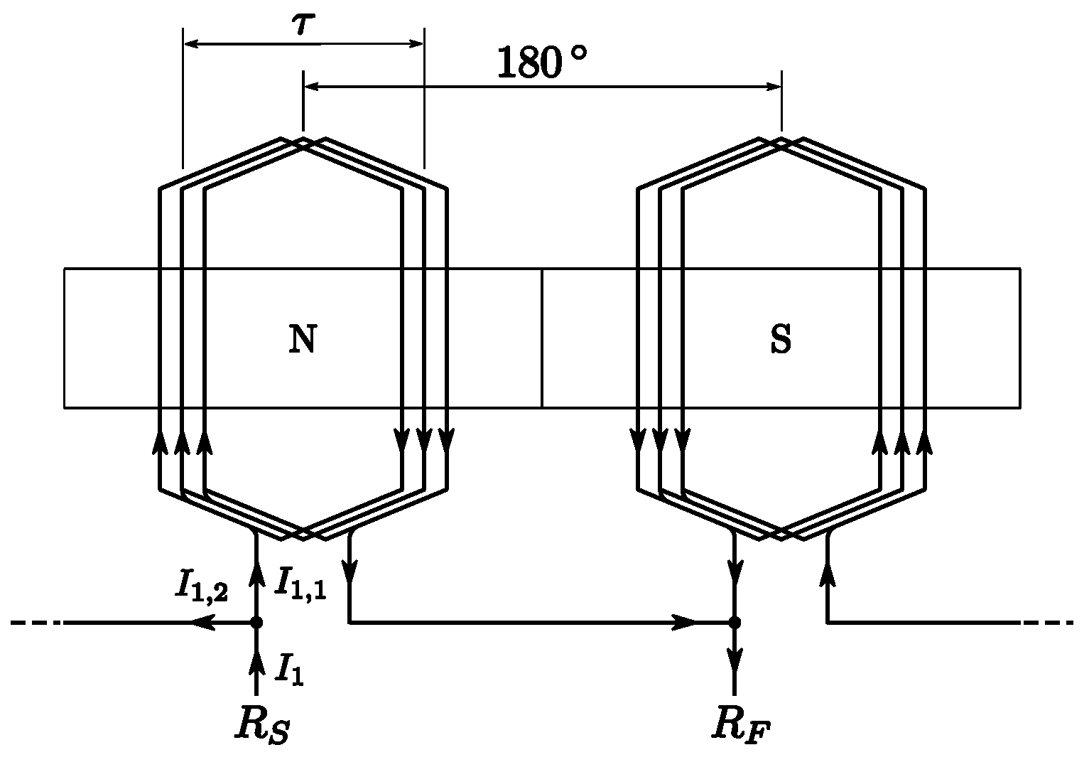
This section briefly describes the general operating principle of a single multifunction winding performing both drive and EDB principles, in the case of a PM rotor with one pole pair. In this case, p = 1, the motor winding also has one pole pair in order to achieve optimal magnetic coupling and to generate a driving torque. An example of such a winding, with a window frame configuration and for one phase, is shown in Figure 1a. Concerning the EDB winding, as explained in [6], when the rotor is an internal rotor, the EDB short-circuited winding has to have two pole pairs (p + 1) to be magnetically coupled to the harmonics linked to the rotor off-centering. An example of such a winding, also with a window frame configuration and for one phase, is shown in Figure 1b. From these figures, it can be seen that these two windings can be combined into one single multifunction winding. This is shown in Figure 2, consistently for one phase. This multifunction winding can be fed through terminals RS and RF to produce a torque: both coils are then connected in an antiparallel configuration. However, this winding also allows for a short circuit path consisting of both coils connected in series. The currents induced when the rotor is moving out-centered can then circulate in this short-circuit path and generate electrodynamic restoring forces.
3. Simplified Analytical Model
We make the following assumptions:
- the materials have linear magnetic characteristics,
- only the highest harmonics in the permanent magnet field distribution are considered,
- the rotor only undergoes translational eccentricity, i.e., the magnetic axis of the rotor and of the winding remain parallel,
- the rotor spin speed is constant.
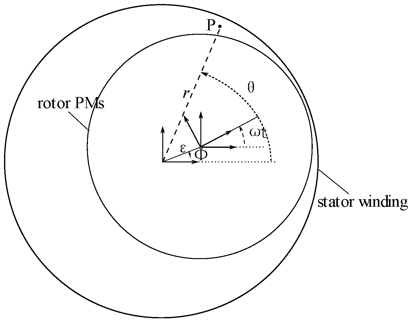
Based on these assumptions, the magnetic vector potential due to the permanent magnet rotor has only one axial component, , which can be derived as described in [6,7]. Finally, when the rotor is internal and has one pole pair, the magnetic vector potential is worth at a point P placed at coordinates (r, θ) from the stator center (as shown in Figure 3):
where A(r) and Ai(r) are the amplitude of the vector potential component of periodicity p = 1 when the rotor is centered and of periodicity p + 1 = 2 when the rotor is off-centered, respectively. They depend on the geometric and magnetic properties of the system. The distance between the rotor and stator center is named ε, and the direction of off-centering is named Φ.
Considering window frame windings connected as illustrated in Figure 2, the magnetic flux seen by each coil of the winding of phase k can be calculated by integrating , along the conductors of these coils, with described in (1). From there, the electromotive forces e(t) generated on each coil is calculated by derivation of the flux , as detailed in [8], resulting in:
where δk represents the angular position of the magnetic axis of the first coil of the winding of phase k. The first EMF (2), with phasor , is generated by the inductor in the windings when the rotor is centered, is independent of the out-centering amplitude and can be linked to the motor behavior of the winding. The flux constant is equal to . The second EMF (3), with phasor , is the EMF induced by the harmonics of the magnetic field appearing when the rotor is not centered. It is proportional to the decentering amplitude, and relates to the EDB behavior of the winding. Its flux constant is equal to . From these equations, it can be seen that there will be a compromise to make on the coil pitch : a coil pitch of 180° maximizes the motor behavior, but cancels the EDB behavior. A coil pitch of 90° maximizes the EDB behavior, but at the expense of a smaller flux constant related to the motor behavior.
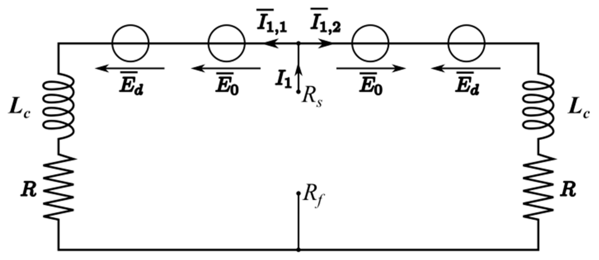
Equivalent electrical circuits for each phase of the multifunction winding can be represented as in Figure 4 [10]. In this circuit, the left and right branches correspond respectively to the coils facing a north or a south pole inside one phase winding. For the case represented in Figure 2 (p = 1), the left branch simply corresponds to the left coil, and the right branch to the right coil. Both branches have the same resistance R, and same cyclic inductance Lc, as each coil inside the winding is identical. Two EMFs appear on each part of the circuit. The motor EMF, E0, has the same sign on both coils of the winding, given the antiparallel connection between them. The bearing EMF, named Ed, has opposite signs for each coil given the series connection of the coils seen by the winding in this case.
The same equations can be written for the N phases of the system.
In Equation (6), the total current refers to the current supplied by the power supply, and it only contributes to the torque generation. Indeed, when the rotor is centered, the induced EMF is equal to zero. The current distribution in each loop is then balanced and equates to:
When the rotor is out-centered, an unbalance between the currents in each loop appears, generated by the EMF Ed. However, the total current I1 remains at the same value as when the rotor is centered:
The bearing restoring forces can be predicted by the state-space model presented in [9], which links the two degrees of freedom point mass rotor dynamic behavior to the electrodynamic forces developed inside a heteropolar bearing.
In the system analyzed in this paper, the electrodynamic bearing function is constituted by two identical coils in series, which means that from a bearing point of view, the winding total inductance and resistance are 2Lc and 2R, and its total flux constant is Considering a system without ferromagnetic yoke (no detent forces), the detent stiffness is zero. When the rotor is a one-pole pair internal rotor, the model parameter representing the electric pulsation of the rotor is equal to . The equation governing the dynamics of the system then becomes:
In this equation, C represents the additional damping in the system, and M is the rotor mass. In quasistatic conditions, i.e., when the rotor is spinning in a fixed out-centered position, these equations can be simplified, and two force components appear: one restoring component, acting to re-center the rotor, and one parasitic component, acting perpendicular to the center shift. In this case, these two components are equal to:
The electrodynamic drag torque produced by the bearing function can be calculated as follows:
4. Prototype and Test Bench
A prototype of a centering heteropolar electrodynamic bearing has been constructed [16] and is used in this article to investigate its passive self-bearing capacities, to eventually confirm the theoretical conclusions of [15], stating that in a slotless configuration, it is possible to simultaneously generate sufficient passive electrodynamic centering forces and a driving torque in a single multifunction winding.
This prototype consists of a one-pole pair permanent magnet rotor, and a three-phase multifunction winding. The one-pole pair permanent magnet is formed by an annular NdFeB permanent magnet with parallel polarization, mounted on the shaft, and generating a sinusoidal magnetic field inside the airgap. Each phase of the stator coils consists of two concentrated window frame coils at 180°. There is no ferromagnetic yoke behind those coils, and the nominal airgap when the rotor is centered is 4 mm. A picture of the prototype is shown in Figure 5, and its characteristics are presented in Table 1.
A sectional schematic representation of the prototype is given in Figure 6, showing the current directions inside the windings when desiring a centering force or a torque, in accordance with the operating principle explained in the previous section.
The test bench is shown in Figure 7. It is designed to operate in quasistatic conditions, i.e., the rotor spins in a fixed out-centered position relatively to the stator. The rotor is driven by an external motor and its radial position is fixed. The stator is mounted on an xy manual stage, allowing displacing the stator with respect to the rotor with a micrometric precision. This test bench configuration allows to get rid of dynamic issues as the rotor is fixed by mechanical bearings. The relative displacement between the stator and the rotor is obtained by adjusting the stator position through the manual stage. The test bench is also equipped with a six-axis force sensor, measuring the reaction forces and torques on the stator winding. Finally, the prototype is encased inside an enclosure for safety.
5. Electromotive Forces
5.1. Experimental Results
An initial experiment was carried out to characterize the electromotive forces on the windings. The windings are left in open circuit, and the induced electromotive forces are measured on the two coils of each of the three phases (m1(t) and m2(t)), which correspond to the phasors and on the equivalent circuit, in Figure 8, for one phase.
The induced EMFs are measured for various center shifts and various spin speeds: on the three phases, for spin speeds of 2400, 3600, 4800, and 6000 rpm, while displacing the rotor in the x–y plane by steps of 0.25 mm, with some additional 0.1 mm steps around the rotor center. A typical example of the obtained measures is shown in Figure 9a: within one phase, each coil presents a signal of the same frequency but with a difference in amplitude, depending on the rotor center shift. Fourier analysis of these signals is shown in Figure 9b and confirms the same frequency of the two signals. It can also be observed that the signal is almost purely sinusoidal, although a very small third harmonic is present.
This signal is postprocessed to extract the first harmonic and corresponding phase of each measure. The amplitude of the first harmonic of these measures is illustrated in Figure 10, for one phase, for different center shifts and spin speeds.
From these two measures obtained for each phase, the amplitudes of the electromotive force Ed, linked to the EDB, and the electromotive force E0, linked to the motor can be deduced:
The results for the bearing EMF Ed and the motor EMF E0 amplitudes deduced from the measurements are shown in Figure 11. It can be observed in Figure 11a and Figure 12 that the motor EMF only depends on the spin speed, but not on the position of the center of the rotor. The results of the measures are very similar for each phase of the prototype. In Figure 11b, it can be observed that the bearing EMF increases proportionally with the center shift, and the slope increases with the spin speed. The bearing EMF measures also show (Figure 13) that due to geometric and magnetic imperfections, the geometric center of the system does not exactly correspond to its magnetic center. In addition, the bearing EMF should be zero when the rotor is perfectly magnetically centered, and the three phases should give the same results. However, we observe that the EMF reaches a minimum value which is situated on slightly different x points for each phase (Figure 13a). Similar observations can be made in the y-direction in Figure 13b. This illustrates that there is a slight dissymmetry between the phases. By displacing the rotor center by steps of 0.1 mm, the exact magnetic center is not found and the bearing EMF minimum value is slightly higher than zero: 0.2 V for the highest value at 6000 rpm. It can also be seen in Figure 13 that the dissymmetry between the phases remains small for all the measured points.
5.2. EMF Experimental Model Comparisons
As shown in Section 3, the model predicts a bearing EMF proportional to the spin speed and to the center shift (3), and a motor EMF only proportional to the spin speed (2). This is indeed observed in Figure 11, Figure 12, and Figure 13. The flux constants and in Equations (2) and (3) can be identified by static FE simulations or by performing curve fitting on the experimental measures, using a least square criterion. To identify those flux constants by FE, a 3D magnetostatic model is constructed as illustrated in Figure 14. The flux due to the permanent magnet rotor intercepted by each coil is calculated by integrating . This is done for one off-centered rotor position and for angular positions of the rotor from 0 to 2π. The flux constants are then calculated by summing ( or subtracting ( the flux values of the two coils of each phase and multiplying by the number of coil turns. For this subtraction has to be divided by the rotor center shift. The numerical values obtained by FE and by curve fitting for these flux constants are given in Table 2.
The bearing flux constant is similar when identified by FE simulations or by curve fitting; however, the motor flux constant is less similar between the two techniques. The measures for each phase and the model predictions, with the parameters identified by curve fitting, are represented in Figure 15, and show good correspondence.
6. Force and Torque
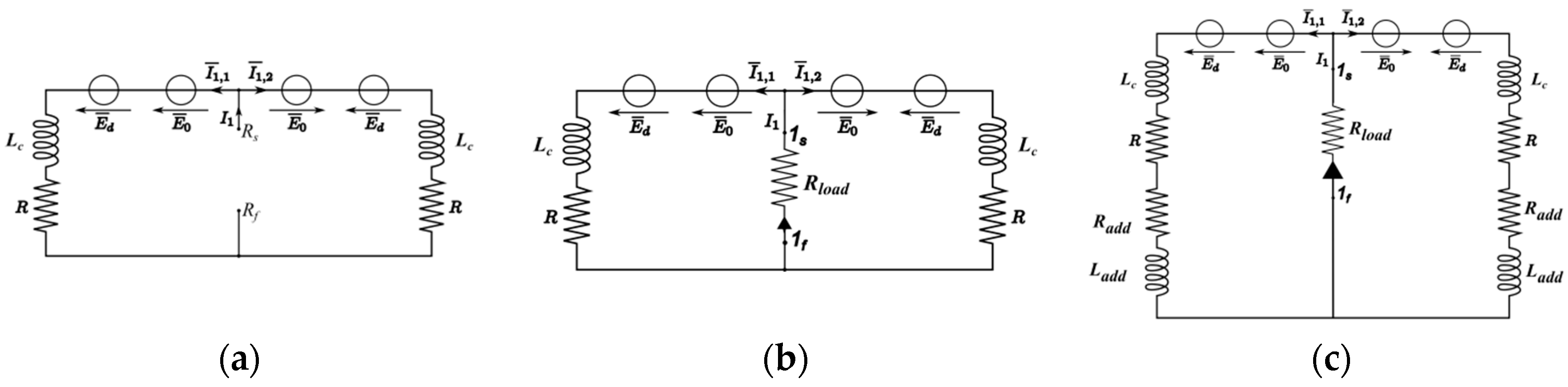
A second experiment was carried out by connecting the two coils of each phase in series, and by driving the rotor by the external motor. A first set of measures on the restoring radial forces and the drag torque was obtained by leaving the motor connections (Figure 16a) of each phase in open circuit, while the prototype is only operating in bearing mode. To investigate the bearing and motor modes, a second set of measures is done by connecting a resistive charge on the motor connections {RS,RF} and by measuring the radial forces and the resistive torque again (Figure 16b). As the torque generation abilities of the prototype are investigated in generator mode by simply connecting a passive element at the coils terminals (a resistance), there is no control over the resulting current phase as would normally be the case for a motor. Finally, the same measures are carried out again, but with a change in the electrical characteristics of the coils. This is achieved by connecting external inductors, characterized by an inductance Ladd and a resistance Radd, on each coil (Figure 16c). This means that the currents flowing through the coils are equal to, for the first case:
For the second case:
And for the third case:
6.1. Bearing Forces
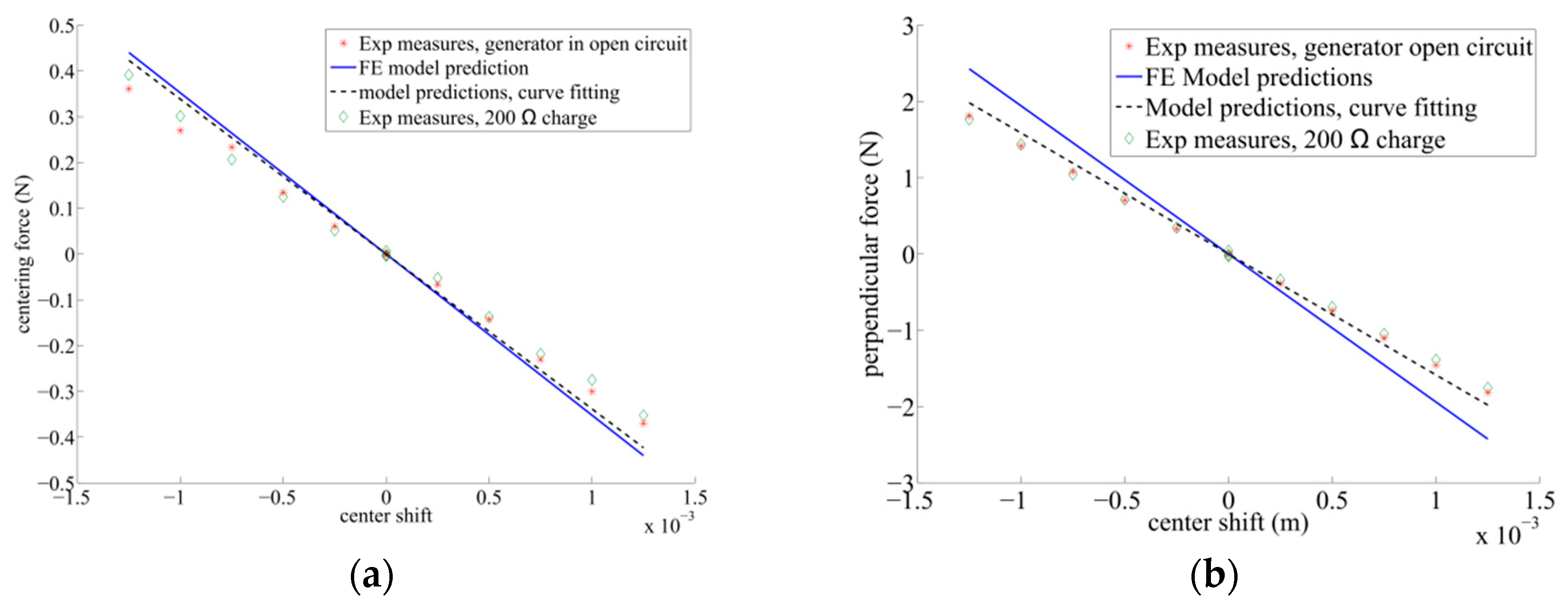
Referring to Equations (13) and (14), the electrodynamic bearing forces are proportional to the center shift. This is indeed observed in Figure 17, for the centering and perpendicular forces, as a function of the rotor displacement along the x-axis, (y-axis centered)for a spin speed of 6000 rpm. Both measures when the generator is left in open circuit, and when it is connected to a Rload = 200 Ω charge, are presented in Figure 17.
It can be observed in Figure 17 that the bearing forces are not influenced by generator behavior at the spin speed of 6000 rpm.
The comparison with the model predictions when its parameters are identified either by FE simulations or by curve fitting, is also shown, and there is a good correspondence. The values of the model parameters for both cases are given in Table 3, and are compared to the experimental measurement of the coil impedance.
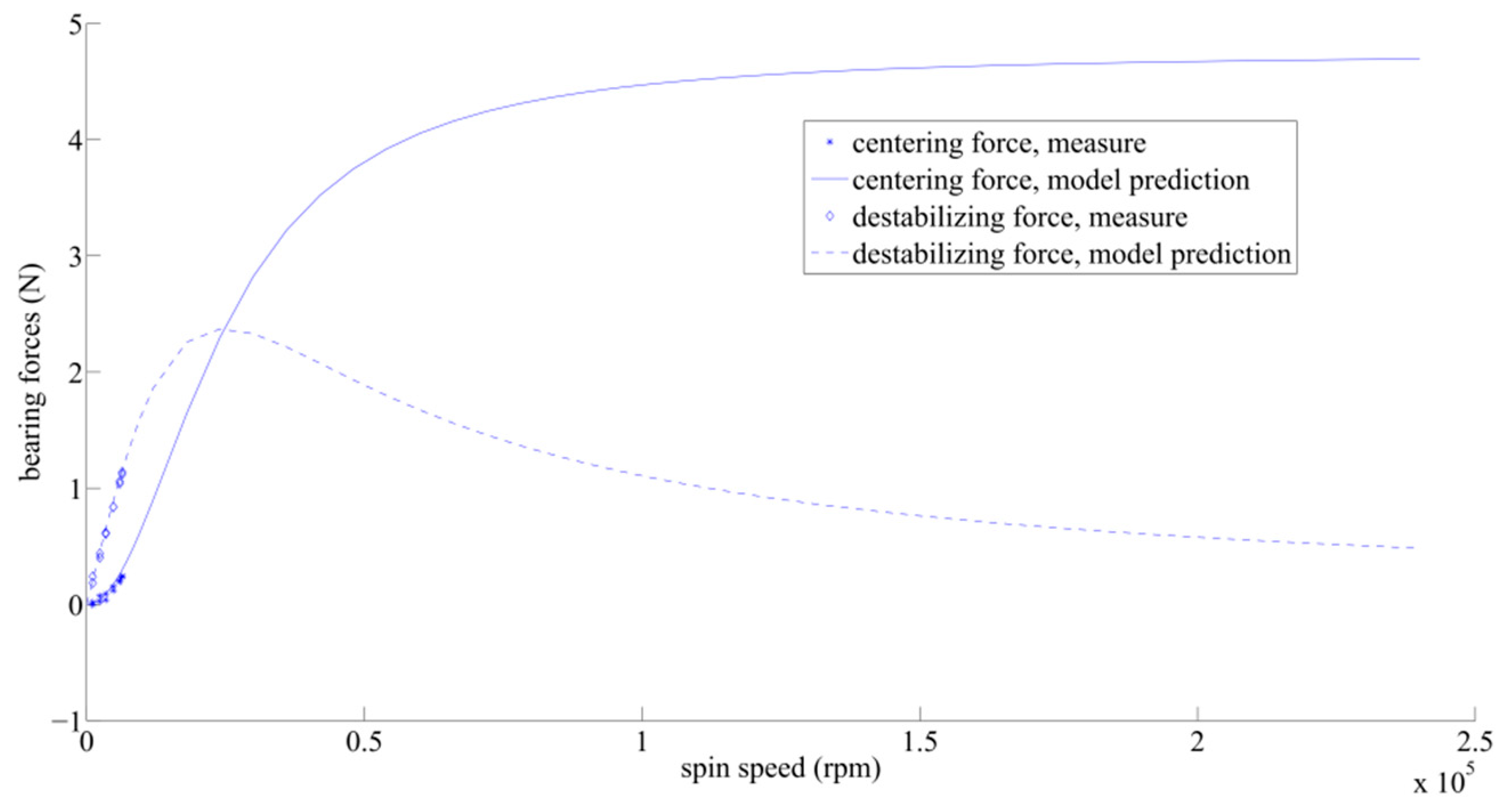
The stiffness reached by the centering force at 6000 rpm can be deduced by the measures illustrated in Figure 17, and it is equal to 297.4 N/m, which is very low. However, the spin speed at which these experimental measures have been accomplished is relatively low for an electrodynamic bearing, as the electrodynamic stiffness developed by electrodynamic bearings increases with the spin speed. It can also be observed in Figure 17 that at the spin speed of 6000 rpm, the destabilizing parasitic force perpendicular to the center shift is more important than the restoring force; 1.8 N versus 0.36 N. This is again due to the fact that, at 6000 rpm, the rotor is not spinning fast enough. The spin speed can be compared to the electrical pole of the coils: the restoring force becomes predominant over the perpendicular force when the spin speed becomes higher than the inverse of the electric time constant of the system , with × 103 rpm [6]. The model predictions for this bearing show (Figure 18) that when extrapolating at higher spin speed, the perpendicular force decreases, and the restoring stiffness increases, as expected.
Measures with Additional Inductors
In order to change the value of , additional inductors have been connected in series with each coil of the prototype (see Figure 16c), the total value of these inductors is given in Table 4.
The bearing forces were measured with and without a resistive load at the motor terminals. First, it can be observed in Figure 19 that in this case, there is a good correspondence between the model predictions and the experimental measures. Moreover, the same observation as in Figure 17 on the coincidence of the measured force values with one additional inductor, with or without resistive charge at the motor terminals, can be obtained: the bearing forces are not influenced by generator behavior. In Figure 19, one can see that at the spin speed of 4800 rpm, the addition of external inductors allows the increase of the restoring component of the force while decreasing the destabilizing perpendicular bearing force. In Figure 20, at 6600 rpm, one can see that with the two additional inductors, the restoring component of the bearing forces becomes higher than the destabilizing one.
When observing the evolution of the bearing forces with the spin speed in Figure 21, one can see that the model predictions and measures are in agreement. With the external inductors, the spin speed is modified and the spin speed above which the centering force becomes predominant is lower. This is confirmed by the experimental measures. However, one can also see that the asymptotic value that can be reached by the centering forces at high spin speed also decreases by adding the external inductors: the external inductors improve the centering force at low spin speed, which is good for our test bench as the spin speed is limited, but is harmful for high spin speed operation. In other words, the maximum stiffness the electrodynamic bearing is able to develop decreases when adding the external inductors.
An additional word should be said on the well-known dynamic stability problems of centering electrodynamic bearings: the force perpendicular to the center shift will produce dynamic instability, and the system needs some damping in order to be dynamically stable when spinning. The dynamics of such a system are studied in detail through root loci in [14] for heteropolar electrodynamic bearings: they will depend on the R-L dynamics of the bearing winding and on the mechanical time constant of the system. Applying the same stability analysis as in [14] on the model presented in Equation (12) in the previous section, and knowing that the rotor mass is equal to 0.27 kg, Figure 22a,b show the root locus that has two stable roots, but one root which remains unstable for any spin speed. The amount of damping that should be added inside the system to achieve stable dynamic behavior can be studied theoretically through this root locus, as shown in Figure 22b: when adding progressive damping of [10 20 30] Ns/m, the spin speed above which the system is dynamically stable decreases to [10550 4460 1600] rad/s, respectively. The influence of the additional inductors can be observed in Figure 22c. They clearly have an influence on the spin speed above which the system is dynamically stable: with external damping of 20 and 30 Ns/m, the system is stable for any spin speed.
However, as all the measures presented in this article were performed in quasistatic conditions, these instabilities do not appear. By consequence, this test bench does not need to add this external damping, which remains a major issue for centering electrodynamic bearings.
6.2. Torque
The torque is first measured with the generator in open circuit and then with a resistive charge connected to its terminals. It can be observed in Figure 23a that when there is no charge on the motor terminal, torque is measured, which corresponds to the electrodynamic drag torque. This torque increases when the center shift increases. When the resistive charge is connected, an additional torque appears, corresponding to the motor torque. It can be observed that the motor torque is more important than the electrodynamic drag torque linked to the bearing function. This motor torque is proportional to the spin speed, as can be seen in Figure 23b, and remains constant while off-centering the rotor. In this figure, it can also be observed that when the rotor remains centered, the electrodynamic torque remains around zero, which confirms the null-flux principle: when the electrodynamic bearing is magnetically centered, the power dissipated inside the windings due to its bearing function is minimal, and no forces are generated.
The torque can be predicted by the state space model, as shown by Equation (15), but can also be predicted by performing a power balance: the power dissipated in the resistive load Rload corresponds to the generator output power, while the power dissipated by the current due to the center shift inside the coil resistances R + Radd corresponds to the electrodynamic drag torque power. Finally, the power dissipated inside the coil resistances R + Radd by the motor current corresponds to the motor Joule losses, and does not produce any torque. This leads to the relations:
The electrodynamic torque model predictions with Equation (15) or (25) give the same results, and they match well with the measures in Figure 23a. The motor torque predicted by the power balance in Equation (26) also coincides with the experimental measures.
In Figure 24, it can be observed that the electrodynamic torque value is noticeably influenced by the additional inductors, while their influence is negligible on the motor torque. Finally, a global remark can be made on the measures shown: the output torque and the centering stiffness are weak. This can be explained by the fact that this electrodynamic heteropolar bearing was first solely intended to demonstrate the null-flux principle in heteropolar EDBs, and this prototype has not undergone any optimization of its performances in the sizing process.
6.3. Current
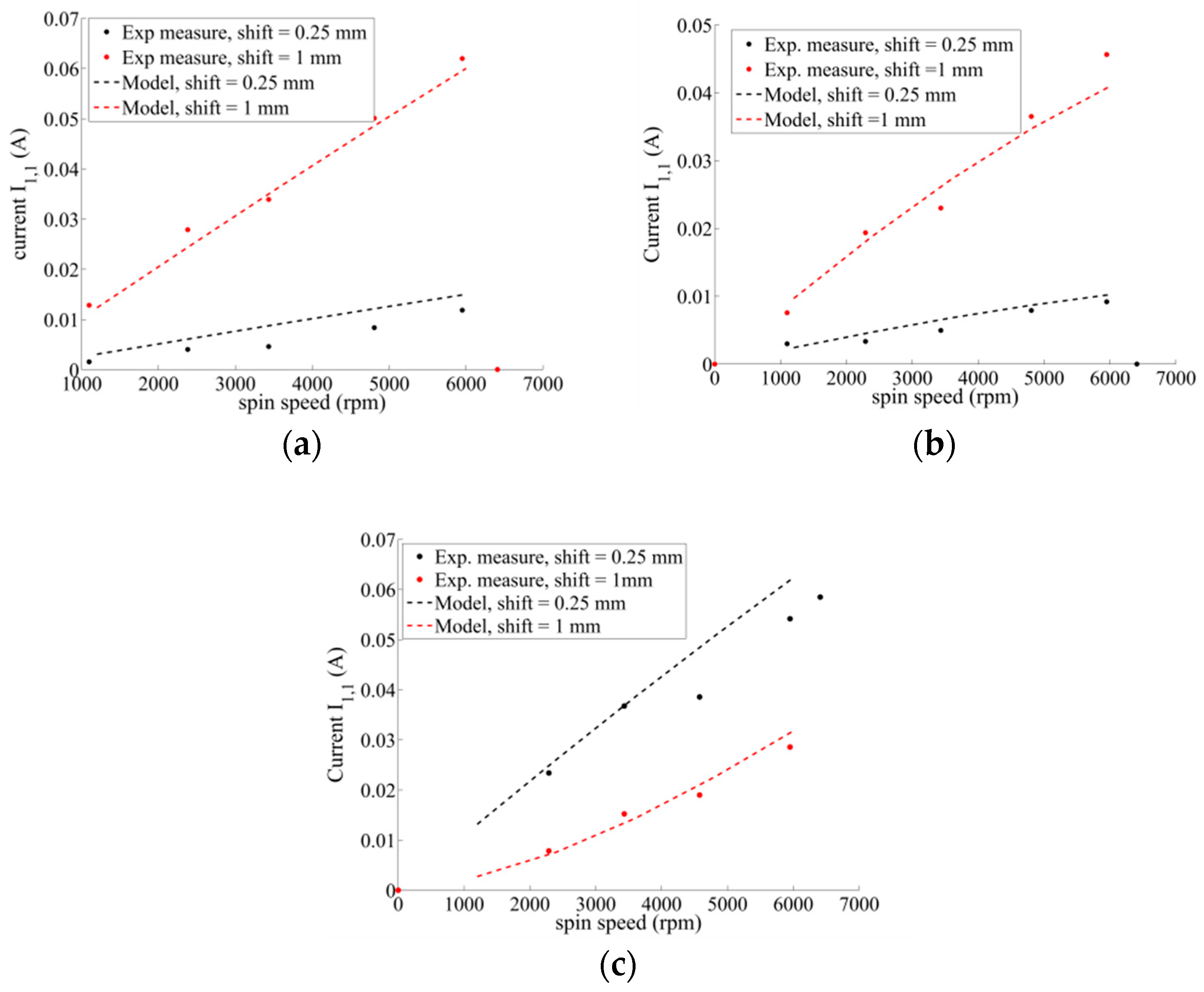
Finally, the current flowing through the coils has also been measured, and is shown in Figure 25 for one phase. It is compared to the current predicted by solving the electrical circuits of Figure 4 that are described in Equations (18–24).
It can be noticed that in the two first cases, when the motor terminals are in open circuit, with or without additional inductors, in Figure 25a,b, the RMS value of the current in the first coil of phase 1 is more important for a center shift of 1 mm than 0.25 mm. Indeed, in these cases, there is no motor current, and the current inside the coils is only due to the bearing function. For the case with a resistive load at motor terminals and one additional inductor on each coil, in Figure 25c, one can notice that the current in the first coil is more important for a center shift of 0.25 mm than for a center shift of 1 mm. This is due to the fact that in this coil, the motor current and the bearing current flow in opposite directions. In contrast, in the second coil, the motor current and the bearing current add up, and the total current is more important for the higher center shift, as the model shows in Figure 26.
7. Conclusions
This paper shows experimental measures made on a heteropolar electrodynamic bearing to evaluate its ability to operate as a passively centered self-bearing permanent magnet rotor. First, the operating principle was briefly explained. Second, EMF measurements showed a motor EMF independent from the rotor center position and a bearing EMF proportional to the rotor displacement. Third, force measurements showed radial force measurements in agreement with electrodynamic centering bearing forces, presenting a restoring component and a component perpendicular to the center shift. It is shown that it is possible to shift the spin speed at which the electrodynamic bearing forces become predominantly centering forces towards lower spin speed by adding additional inductors in series on each coil of the prototype. It is also shown that the bearing forces are independent of the load connected to the motor terminals. Fourth, the torque measurements show an electrodynamic drag torque depending on the rotor position, and a motor torque proportional to the spin speed. The electrodynamic drag torque is influenced by the additional inductors, while the motor torque is almost not influenced by additional inductors. Finally, the current flowing in the coils was accurately predicted by the equivalent circuit models.
Despite the low produced torque and high stiffness, these experimental measures confirm the feasibility of the operating principle for a slotless winding without ferromagnetic yoke and a permanent magnet rotor. However, two major issues remain before realizing a completely passive self-bearing motor based on a radial electrodynamic bearing: the introduction of passive axial forces without impeding the radial stiffness developed by the radial electrodynamic bearing, and the introduction of sufficient damping in the system to counter the dynamic instabilities inherent to centering electrodynamic bearings.
Author Contributions
Writing—original draft, V.K.; Writing—review & editing, J.V.V. and B.D.
Funding
This research was funded by the university UCLouvain.
Conflicts of Interest
The authors declare no conflict of interest.
References
- Severson, E.L.; Nilssen, R.; Undeland, T.; Mohan, N. Design of dual purpose no-voltage combined windings for bearingless motors. IEEE Trans. Ind. Appl. 2017, 53, 4368–4379. [Google Scholar] [CrossRef]
- Xu, Z.; Lee, D.H.; Ahn, J.W. Comparative analysis of bearingless switched reluctance motors with decoupled suspending force control. IEEE Trans. Ind. Appl. 2014, 51, 733–743. [Google Scholar] [CrossRef]
- Zhao, C.; Zhu, H. Design and analysis of a novel bearingless flux-switching permanent magnet motor. IEEE Trans. Ind. Electron. 2017, 64, 6127–6136. [Google Scholar] [CrossRef]
- Gruber, W.; Rothböck, M.; Schöb, R.T. Design of a novel homopolar bearingless slice motor with reluctance rotor. IEEE Trans. Ind. Appl. 2014, 51, 1456–1464. [Google Scholar] [CrossRef]
- Mitterhofer, H.; Mrak, B.; Gruber, W. Comparison of high-speed bearingless drive topologies with combined windings. IEEE Trans. Ind. Appl. 2014, 51, 2116–2122. [Google Scholar] [CrossRef]
- Chiba, A.; Fukao, T.; Rahman, M.A. Vibration suppression of a flexible shaft with a simplified bearingless induction motor drive. IEEE Trans. Ind. Appl. 2008, 44, 745–752. [Google Scholar] [CrossRef]
- Laiho, A.; Sinervo, A.; Orivuori, J.; Tammi, K.; Arkkio, A.; Zenger, K. Attenuation of harmonic rotor vibration in a cage rotor induction machine by a self-bearing force actuator. IEEE Trans. Magn. 2009, 45, 5388–5398. [Google Scholar] [CrossRef]
- Xin, C.; Zhiquan, D.; Xiaolin, W. Vibration reduction with radial force windings short-circuited in bearingless switched reluctance motors. In Proceedings of the 2009 4th IEEE Conference on Industrial Electronics and Applications, Xi’an, China, 25–27 May 2009; pp. 2630–2634. [Google Scholar]
- Kluyskens, V.; Dehez, B. Dynamical electromechanical model for magnetic bearings subject to eddy currents. IEEE Trans. Magn. 2012, 49, 1444–1452. [Google Scholar] [CrossRef]
- Detoni, J.G. Progress on electrodynamic passive magnetic bearings for rotor levitation. Proc. Inst. Mech. Eng. Part C J. Mech. Eng. Sci. 2014, 228, 1829–1844. [Google Scholar] [CrossRef]
- Amati, N.; de Lépine, X.; Tonoli, A. Modeling of Electrodynamic Bearings. J. Vib. Acoust. 2008, 130, 61007. [Google Scholar] [CrossRef]
- Filatov, A.V.; Maslen, E.H. Passive magnetic bearing for flywheel energy storage systems. IEEE Trans. Magn. 2001, 37, 3913–3924. [Google Scholar] [CrossRef]
- Dumont, C.; Kluyskens, V.; Dehez, B. Null-flux radial electrodynamic bearing. IEEE Trans. Magn. 2014, 50, 1–12. [Google Scholar] [CrossRef]
- Dumont, C.; Kluyskens, V.; Dehez, B. Linear state-space representation of heteropolar electrodynamic bearings with radial magnetic field. IEEE Trans. Magn. 2015, 52, 1–9. [Google Scholar] [CrossRef]
- Kluyskens, V.; Dumont, C.; Dehez, B. Description of an electrodynamic self-bearing permanent magnet machine. IEEE Trans. Magn. 2016, 53, 1–9. [Google Scholar] [CrossRef]
- Kluyskens, V.; Dumont de Chassart, C.; Dehez, B. Design and experimental testing of a heteropolar electrodynamic bearing. In Proceedings of the 2th IEEE Conference on Advances in Magnetics, La Thuile, Italy, 4–7 February 2018. [Google Scholar]
- Kluyskens, V.; van Verdeghem, J.; Dumont, C.; Dehez, B. Experimental Investigations on a Heteropolar Electrodynamic Bearing-self-bearing Motor. In Proceedings of the 16th International Symposium on Magnetic Bearings (ISMB), Beijing, China, 13–17 August 2018. [Google Scholar]
Figure 1.
Unrolled view of a one-pole pair permanent magnet rotor with one phase (a) of a motor winding and (b) of an electrodynamic bearing winding if the rotor is internal.
Figure 1.
Unrolled view of a one-pole pair permanent magnet rotor with one phase (a) of a motor winding and (b) of an electrodynamic bearing winding if the rotor is internal.

Figure 2.
Unrolled view of phase 1 of a multifunction winding performing both motor and passive electrodynamic magnetic bearing (EDB) centering functions for a one-pole pair internal permanent magnet rotor.
Figure 2.
Unrolled view of phase 1 of a multifunction winding performing both motor and passive electrodynamic magnetic bearing (EDB) centering functions for a one-pole pair internal permanent magnet rotor.

Figure 3.
Frames and coordinates used for the model.

Figure 4.
Equivalent electrical circuit of phase 1 of a multifunction winding for a one-pole pair internal inductor, with R the resistance of one coil, Lc, the cyclic inductance of one coil, , the electromotive force (EMF) when the rotor is centered and , the EMF linked to the center shift.
Figure 4.
Equivalent electrical circuit of phase 1 of a multifunction winding for a one-pole pair internal inductor, with R the resistance of one coil, Lc, the cyclic inductance of one coil, , the electromotive force (EMF) when the rotor is centered and , the EMF linked to the center shift.

Figure 5.
Picture of (a) One stator coil, (b) the stator, (c), the rotor, and (d) the centering heteropolar electrodynamic bearing prototype, investigated for its torque generation and self-centering capacities.
Figure 5.
Picture of (a) One stator coil, (b) the stator, (c), the rotor, and (d) the centering heteropolar electrodynamic bearing prototype, investigated for its torque generation and self-centering capacities.

Figure 6.
Schematic view of the prototype, with the current directions inside each phase resulting in (a) an electrodynamic centering force and (b) a motor torque.
Figure 6.
Schematic view of the prototype, with the current directions inside each phase resulting in (a) an electrodynamic centering force and (b) a motor torque.

Figure 7.
Picture of the test bench for operation of the prototype in quasistatic conditions, with an external motor to drive the rotor.
Figure 7.
Picture of the test bench for operation of the prototype in quasistatic conditions, with an external motor to drive the rotor.

Figure 8.
Principle of experimental measurements of the EMF shown on equivalent electrical circuit.

Figure 9.
(a) Measured voltages and (b) Fourier analysis of measured voltages on phase 1 for a spin speed of 6000 rpm and a rotor center shift of 1 mm (along the y-axis).
Figure 9.
(a) Measured voltages and (b) Fourier analysis of measured voltages on phase 1 for a spin speed of 6000 rpm and a rotor center shift of 1 mm (along the y-axis).

Figure 10.
Root Mean square (RMS) value of first harmonic measured induced voltages at the coil terminals of phase 1, as a function of a rotor displacement along the y-axis, while centered along the x-axis, for rotor spin speeds of 2400, 3600, 4800, and 6000 rpm.
Figure 10.
Root Mean square (RMS) value of first harmonic measured induced voltages at the coil terminals of phase 1, as a function of a rotor displacement along the y-axis, while centered along the x-axis, for rotor spin speeds of 2400, 3600, 4800, and 6000 rpm.

Figure 11.
RMS values of (a) motor electromotive force E0 and (b) bearing electromotive force Ed as a function of the rotor position in the x–y plane for spin speeds of 2400, 3600, 4800, and 6000 rpm.
Figure 11.
RMS values of (a) motor electromotive force E0 and (b) bearing electromotive force Ed as a function of the rotor position in the x–y plane for spin speeds of 2400, 3600, 4800, and 6000 rpm.

Figure 12.
RMS values of motor electromotive force E0 for each phase as a function of the rotor position (a) in the x axis and (b) in the y axis for spin speeds of 2400, 3600, 4800, and 6000 rpm.
Figure 12.
RMS values of motor electromotive force E0 for each phase as a function of the rotor position (a) in the x axis and (b) in the y axis for spin speeds of 2400, 3600, 4800, and 6000 rpm.

Figure 13.
RMS values of bearing electromotive force Ed for each phase as a function of the rotor position (a) in the x axis and (b) in the y axis for spin speeds of 2400, 3600, 4800, and 6000 rpm.
Figure 13.
RMS values of bearing electromotive force Ed for each phase as a function of the rotor position (a) in the x axis and (b) in the y axis for spin speeds of 2400, 3600, 4800, and 6000 rpm.

Figure 14.
Mesh of the 3D Finite Element (FE) magnetostatic model of the prototype.

Figure 15.
Experimental and model predictions for the three phases (a) of the motor electromotive force E0 at spin speeds of 2400, 3600, 4800, and 6000 rpm and (b) of the bearing electromotive force Ed, at a spin speed of 6000 rpm as a function of the rotor position in the y-axis.
Figure 15.
Experimental and model predictions for the three phases (a) of the motor electromotive force E0 at spin speeds of 2400, 3600, 4800, and 6000 rpm and (b) of the bearing electromotive force Ed, at a spin speed of 6000 rpm as a function of the rotor position in the y-axis.

Figure 16.
Electrical circuit for the experimental measurements with (a) the motor connections in open circuit, (b) a resistive charge at motor connections, and (c) with additional inductors and a resistive charge at the motor connections.
Figure 16.
Electrical circuit for the experimental measurements with (a) the motor connections in open circuit, (b) a resistive charge at motor connections, and (c) with additional inductors and a resistive charge at the motor connections.

Figure 17.
Bearing forces as a function of the rotor displacement (x-axis) for a spin speed of 6000 rpm. Measures when the generator is left in open circuit, and when connected to a 200 Ω charge, and comparison with the model predictions; (a) restoring force and (b) destabilizing force.
Figure 17.
Bearing forces as a function of the rotor displacement (x-axis) for a spin speed of 6000 rpm. Measures when the generator is left in open circuit, and when connected to a 200 Ω charge, and comparison with the model predictions; (a) restoring force and (b) destabilizing force.

Figure 18.
Bearing forces as a function of the spin speed for a center shift of 0.75 mm, experimental measures, and model predictions with model parameters identified by curve fitting.
Figure 18.
Bearing forces as a function of the spin speed for a center shift of 0.75 mm, experimental measures, and model predictions with model parameters identified by curve fitting.

Figure 19.
(a) Restoring force and (b) destabilizing bearing forces as a function of the rotor displacement along the x-axis while centered along the y-axis for a spin speed of 4800 rpm. Measures with and without additional inductors when the generator is left in open circuit and when connected to a 200 Ω charge, and comparison to the model when its parameters are identified by curve fitting.

Figure 20.
Bearing forces when adding two additional inductors in series with each coil as a function of the center shift for a spin speed of 6600 rpm.
Figure 20.
Bearing forces when adding two additional inductors in series with each coil as a function of the center shift for a spin speed of 6600 rpm.

Figure 21.
Bearing forces when adding additional inductors in series with each coil as a function of the spin speed for a center shift of 0.75 mm.
Figure 21.
Bearing forces when adding additional inductors in series with each coil as a function of the spin speed for a center shift of 0.75 mm.

Figure 22.
Theoretical root locus for the electrodynamic bearing prototype dynamic behavior. (a) All roots; (b) influence of external damping; and (c) theoretical root locus for the electrodynamic bearing prototype dynamic behavior when adding two external inductors and influence of external damping.

Figure 23.
Measured and predicted torque without additional inductors (a) as a function of the rotor displacement along the x-axis, while centered along the y-axis for a spin speed of 6000 rpm and (b) as a function of the spin speed when the rotor is centered. Measures when the generator is left in open circuit and when connected to a 200 Ω charge.

Figure 24.
Measured and predicted torque, when the generator is connected to a 200 Ω charge (a) as a function of the rotor displacement along the x-axis while centered along the y-axis for a spin speed of 6000 rpm and (b) as a function of the spin speed when the rotor is centered. Measurements were conducted with and without external inductors.

Figure 25.
Measured and predicted current in first coil of first phase for center shifts of 0.25 and 1 mm in the case of the electrodynamic bearing prototype with (a) motor terminals in open circuit, (b) motor terminals in open circuit with one additional inductor on each coil, and (c) motor terminals with resistive load of 200 Ω and one additional inductor on each coil.

Figure 26.
Predicted current in the second coil of the first phase for center shifts of 0.25 and 1 mm in the case of the electrodynamic bearing prototype with motor terminals with resistive load of 200 Ω and one additional inductor on each coil.
Figure 26.
Predicted current in the second coil of the first phase for center shifts of 0.25 and 1 mm in the case of the electrodynamic bearing prototype with motor terminals with resistive load of 200 Ω and one additional inductor on each coil.


Table 1.
Characteristics of the prototype.
| Parameter | Value |
|---|---|
| Outer PM rotor diameter | 25 mm |
| Inner PM rotor diameter | 15 mm |
| Height of PM rotor | 50 mm |
| Rotor magnet | NdFeB |
| PM remanence | 1.3 T |
| Rotor shaft | Steel |
| Coil turns | 560 |
| Number of coils/phase | 2 |
| Number of phases | 3 |
| Coil wire diameter | 0.2 mm |
| Coil total height | 62 mm |
| Coil total width | 17 mm |
| Coil thickness | 4 mm |
| Stator inner diameter | 33 mm |
| Nominal airgap | 4 mm |
Table 2.
EMF model parameter identification.
| Parameter | FE Identification | Exp. Curve Fitting | Relative Difference |
|---|---|---|---|
| 0.0473 | 0.0389 | 21.6% | |
| 4.8442 | 4.1366 | 14.6% |
Table 3.
EMF model parameter identification.
| Parameter | FE Value | Exp. Measure | Curve Fitting |
|---|---|---|---|
| 44.11 | 42.08 | 42.1 | |
| 0.0127 | 0.0162 | 0.0143 |
Table 4.
Additional inductor values.
| Case | |||
|---|---|---|---|
| One additional inductor | 11.17 | 38.7 | 9600 |
| Two additional inductors | 17.01 | 79.1 | 6040 |
© 2019 by the authors. Licensee MDPI, Basel, Switzerland. This article is an open access article distributed under the terms and conditions of the Creative Commons Attribution (CC BY) license (http://creativecommons.org/licenses/by/4.0/).
Share and Cite
MDPI and ACS Style
Kluyskens, V.; Van Verdeghem, J.; Dehez, B. Experimental Investigations on Self-Bearing Motors with Combined Torque and Electrodynamic Bearing Windings. Actuators 2019, 8, 48. https://doi.org/10.3390/act8020048
AMA Style
Kluyskens V, Van Verdeghem J, Dehez B. Experimental Investigations on Self-Bearing Motors with Combined Torque and Electrodynamic Bearing Windings. Actuators. 2019; 8(2):48. https://doi.org/10.3390/act8020048
Chicago/Turabian StyleKluyskens, Virginie, Joachim Van Verdeghem, and Bruno Dehez. 2019. "Experimental Investigations on Self-Bearing Motors with Combined Torque and Electrodynamic Bearing Windings" Actuators 8, no. 2: 48. https://doi.org/10.3390/act8020048
Note that from the first issue of 2016, this journal uses article numbers instead of page numbers. See further details here.