A Critical Analysis of Valve-Compensated Hydrostatic Actuators: Qualitative Investigation


1
Department of Mechanical Engineering, Federal Institute of Science and Technology of the State of Pernambuco, Recife, CEP 50740-545, Brazil
2
Department of Mechanical Engineering, The University of Manitoba, Winnipeg, MB R3T-5V6, Canada
*
Author to whom correspondence should be addressed.
Actuators 2019, 8(3), 59; https://doi.org/10.3390/act8030059
Submission received: 29 May 2019
/
Revised: 22 July 2019
/
Accepted: 28 July 2019
/
Published: 30 July 2019
Abstract
:Hydrostatic actuation has gained interest from both academia and industry due to the unquestionable energetic advantages when compared to valve-controlled actuators; the main feature being the absence of throttling losses due to the direct control of the cylinder by the pump. However, the fact that the great majority of applications are based on single-rod cylinders has been both a challenge and a source of inspiration for a variety of different circuit designs. In an attempt to compensate for the uneven flows coming in and out of differential cylinders, several solutions have been proposed, including the use of hydraulic transformers, individual pumps connected to the cylinder ports or pumps with unmatched input and output flows. The simplest approach, however, seems to be the use of compensation valves in the circuit, which is the focus of this paper. Here, we analyse some representative circuits proposed along the years in a direct and elucidative manner, showing that the definitive solution to the single-rod actuator control problem has been established, paving the road for introducing stable and trustworthy circuits, which can be commercially used in the near future.
1. Introduction and Problem Definition
It has been reported that the power transfer between pump and cylinder in pump-controlled actuators can be nearly 100% efficient, in comparison with the relatively poor efficiency of valve-controlled actuators (e.g., 67% efficiency reported in [1]). This fact alone makes pump-controlled actuators energetically superior when compared to valve-controlled actuators. In addition, the possibility of coupling an electric motor directly to a hydraulic pump without control valves or oil reservoirs allows for the building of compact units, which are particularly useful for the aeronautical industry.
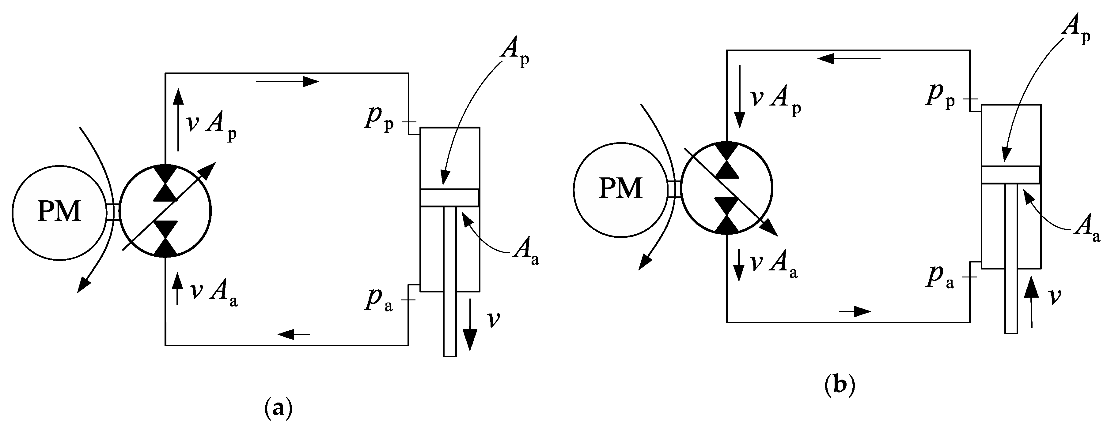
Focusing on pump-controlled actuators, we are faced with the problem of the differential cylinder areas. Figure 1 shows what happens when one tries to connect a pump and a differential cylinder in a direct manner. Pressures and the areas at the cap and rod-sides of the cylinder are , , and , respectively. In the first case (Figure 1a), the flow into the cylinder is higher than the flow out of the cylinder. As a result, there is not sufficient fluid to feed the pump at the input port. The pressure , in this case, would soon become too low and the circuit would become impractical. If the pump displacement is reversed as in Figure 1b, the opposite situation happens as a higher flow is forced into the pump input, increasing the pressure . There is a need for a circuit that supplies the missing flow into the cylinder rod-side when the pump operates as in Figure 1a and removes the excess flow from the cylinder cap-side when the pump operates as in Figure 1b.
Several designs aiming to fulfil the above requirement have been proposed through the years. Briefly, the solutions can be divided into two categories: Valve compensation and pump compensation.
Valve-compensated circuits are those in which the circuit flows are matched by connecting the cylinder ports to a low-pressure reservoir (or to any kind of charge circuit) using valves. Pump-compensated circuits, on the other hand, employ pumps to provide the matching flow into or out of the circuit as needed. In this paper we only address valve-compensated circuits.
2. Basic Designs
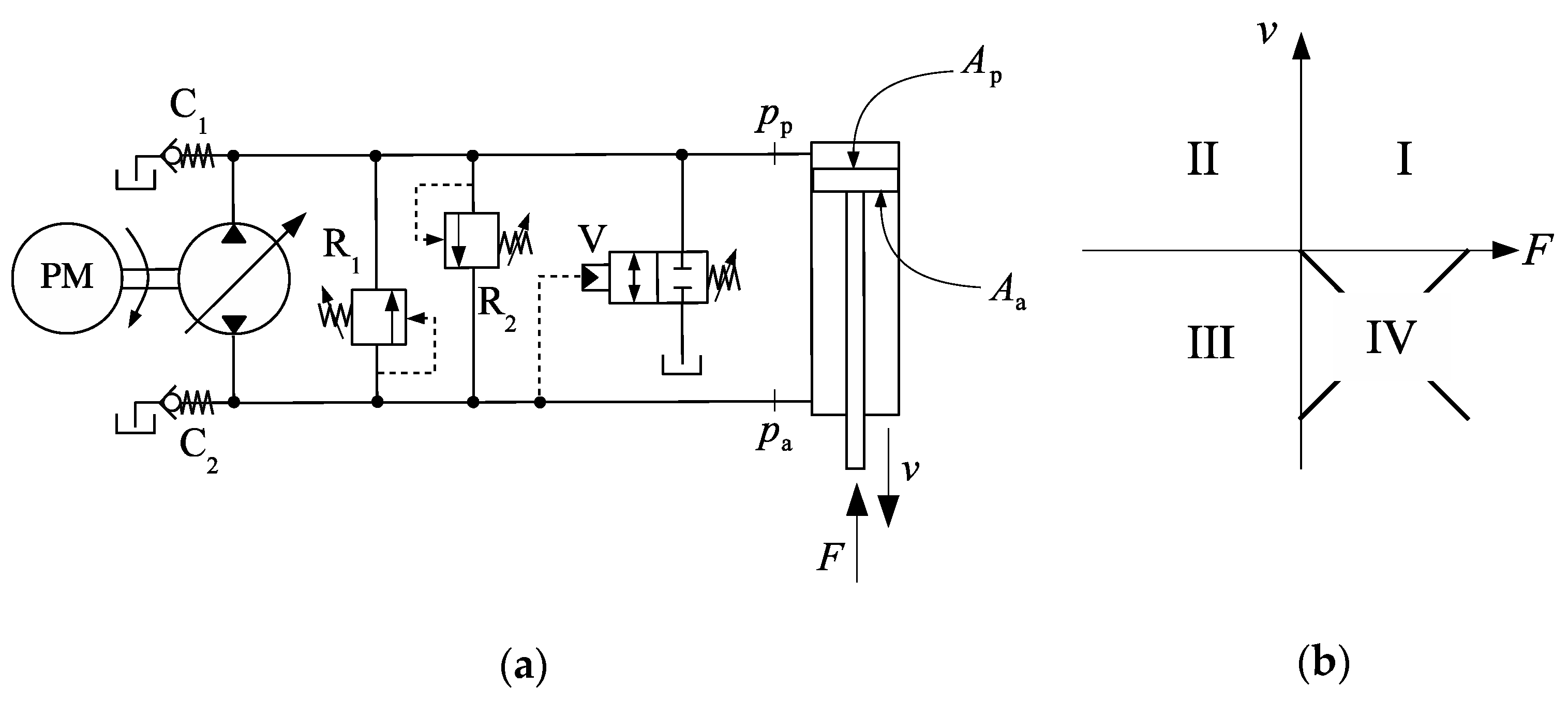
Attempts to solve the flow-matching problem in single-rod actuators have been made for a long time. Frankenfield [2], for example, proposed the circuit shown in Figure 2a. The quotation is, in fact, a reprint of a first edition published in 1979, which, to the best of our knowledge, is the first reference to a circuit of that kind. In Figure 2a, the cylinder is connected to the variable-displacement pump in a closed circuit and can be driven in both directions by adjusting the pump flow. Two relief valves, R1 and R2, are placed in the circuit for pressure spike protection. These valves are mandatory for every hydrostatic actuator, although they will not be represented in the remaining circuits of this paper for the sake of clarity. The check valves C1 and C2 connect both sides of the cylinder to the tank, keeping the circuit pressure above a minimum value.
Figure 2b shows the external force versus velocity diagram, which can be divided into four operational quadrants, characterized by the directions of the velocity, , and the external force, . Thus, considering that the velocity is positive when the cylinder is extending and that the force is positive when it pushes against the cylinder rod, the following combinations give the operational quadrants, I, II, III and IV, in a sequence: ; , and . Given this division, it has been common sense that when the signs of and are opposite, energy is transferred from the load to the pump and the actuator operates in motoring mode. Otherwise, it operates in pumping mode. As seen later in Section 5, we do not favor such division.
The circuit shown in Figure 2a can operate in quadrants I, II and III, but operation in the fourth quadrant is poor. Figure 3 shows how the circuit behaves at different quadrants. Observe that during the fourth quadrant, a flow, , is forced into the pump. Since the pump output and input flows must be the same, the same flow, , is sent into the rod-side. At some point, the pressures at both sides of the circuit rise because the flow coming from the pump cannot be taken in by the rod-side chamber. As the pressures at the rod-side and cap-side rise simultaneously, the directional valve, V, eventually opens up and the cylinder accelerates to the left without control. In the sequence, the directional valve closes again because of the pressure drop at the rod-side. In the end, the result is an uncontrolled and jolty fourth-quadrant operation. Note the crucial role of the directional valve, V, which is responsible for compensating the uneven flows into and out of the pump. We therefore find it appropriate to use the term compensation valve to denote valve V.
The design shown in Figure 2a and Figure 3 holds some characteristics that are present in many other circuits proposed since then. First, we note that the change in the compensation valve position is carried out automatically by directly sensing the pressure at the rod-side. Second, we note that it is possible to have the load driving the pump in the second quadrant, but not in the fourth quadrant. Thus, we may term this actuator as partially motored, meaning that the pump can be motored by the load, but not in every operational quadrant. Following this rationale, we may classify hydrostatic actuators as unmotored and motored. Unmotored actuators are not able to recover energy in any motoring quadrant, while motored actuators can be used to recover energy in both motoring quadrants (II and IV in Figure 3).
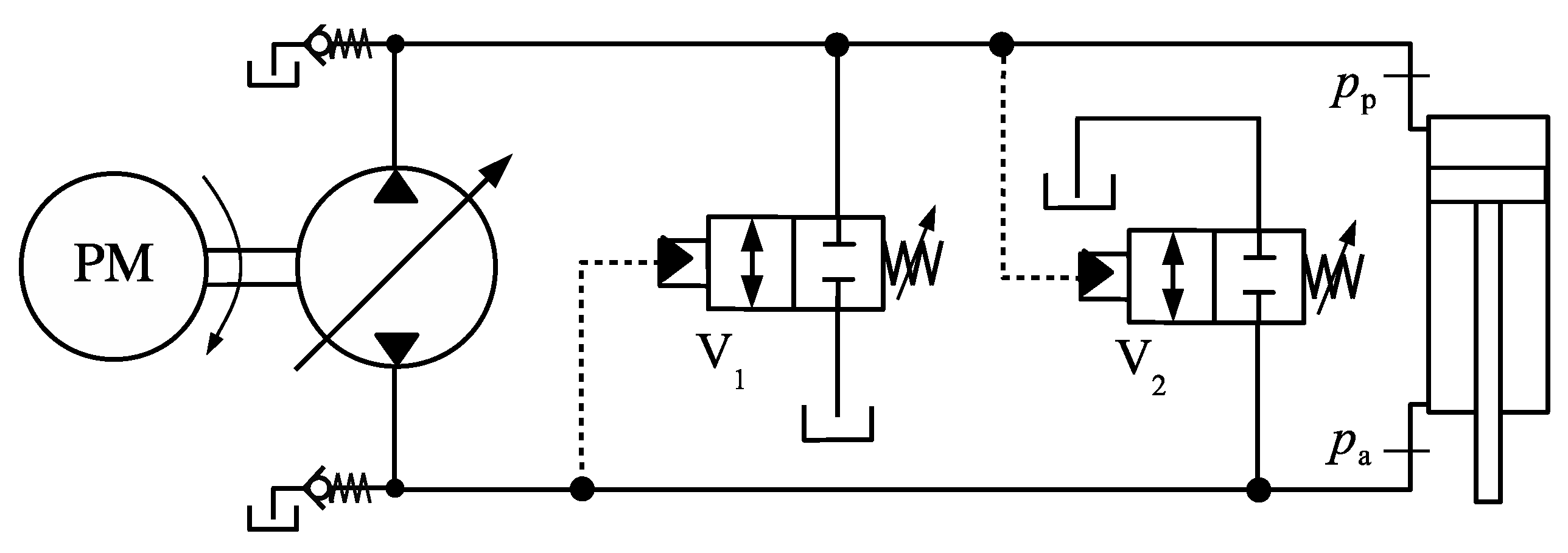
Observe that a sound fourth-quadrant operation of the circuit in Figure 3 would require the directional valve, V, to be closed while draining the excess of fluid coming from the rod-side to the tank. Figure 4 shows one possible solution, where the additional valve, V2, sensing the cap-side pressure, connects the rod-side to the tank.
Hewett [3] proposed the design shown in Figure 5, where we also illustrate its four-quadrant operation. Although nothing is said about the way in which the compensation valve is controlled in the original patent, we just assume that V is solenoid activated. Clearly, some kind of input must be read from the circuit to activate the compensation valve. The pressures on the cap and rod-side of the cylinder are typically used as inputs although other information, such as the cylinder rod position and speed, may be adopted as well [4]. The circuit shown in Figure 5 is an example of a motored actuator.
Motored and partially motored actuators can also be classified into regenerative and non-regenerative. The actuators introduced so far are examples of non-regenerative actuators because they do not regenerate energy during motoring quadrants. Regenerative designs have been reported in References [5,6,7].
Figure 6 shows a circuit using piloted check valves [8,9,10]. The two check valves, C1 and C2, sense the rod and cap-side pressures, respectively, connecting the cap and rod-sides to the charge circuit whose pressure is limited by the relief valve R. When the cap-side pressure is higher than the rod-side pressure, valve C2 opens, connecting the rod-side to the charge circuit. When the rod-side pressure is higher than the cap-side pressure, valve C1 opens, connecting the charge circuit to the cap-side. This is an example of a motored circuit because the pump absorbs energy from the load in both quadrants II and IV.
Figure 7a shows another circuit [11] where a 3 × 3 directional valve (VC) compensates for the uneven cap and rod-side flows (the cracking pressures at each side of the valve, and , are different). Two externally activated 2 × 2 valves are added to dampen out pressure oscillations. The circuit in Figure 7b, proposed in [12], is almost identical to the one in Figure 7a; the only difference being in the central position of the 3 × 3 directional valve, which allows for a limited leakage between the high-pressure line and the charge circuit. The addition of leakage in the central position of the directional valve in Figure 7b aims to correct some pressure oscillations caused by commuting between the charge circuit and the two sides of the cylinder.
Observe that in the circuits shown in Figure 4, Figure 6 and Figure 7, the compensation valves (V1, V2, C1, C2 and VC) are switched by directly sensing the pressure on the cap and rod sides. We therefore think it is appropriate to coin the term direct sensing (DS) to categorize circuits using this kind of compensation as opposed to indirect sensing (IS) circuits, where the compensation valve is activated by means of an external stimulus, as in Figure 5. DS systems have also been termed type A switched systems, following the nature of the system dynamics [13]. Likewise, IS systems can be identified as type B switched systems.
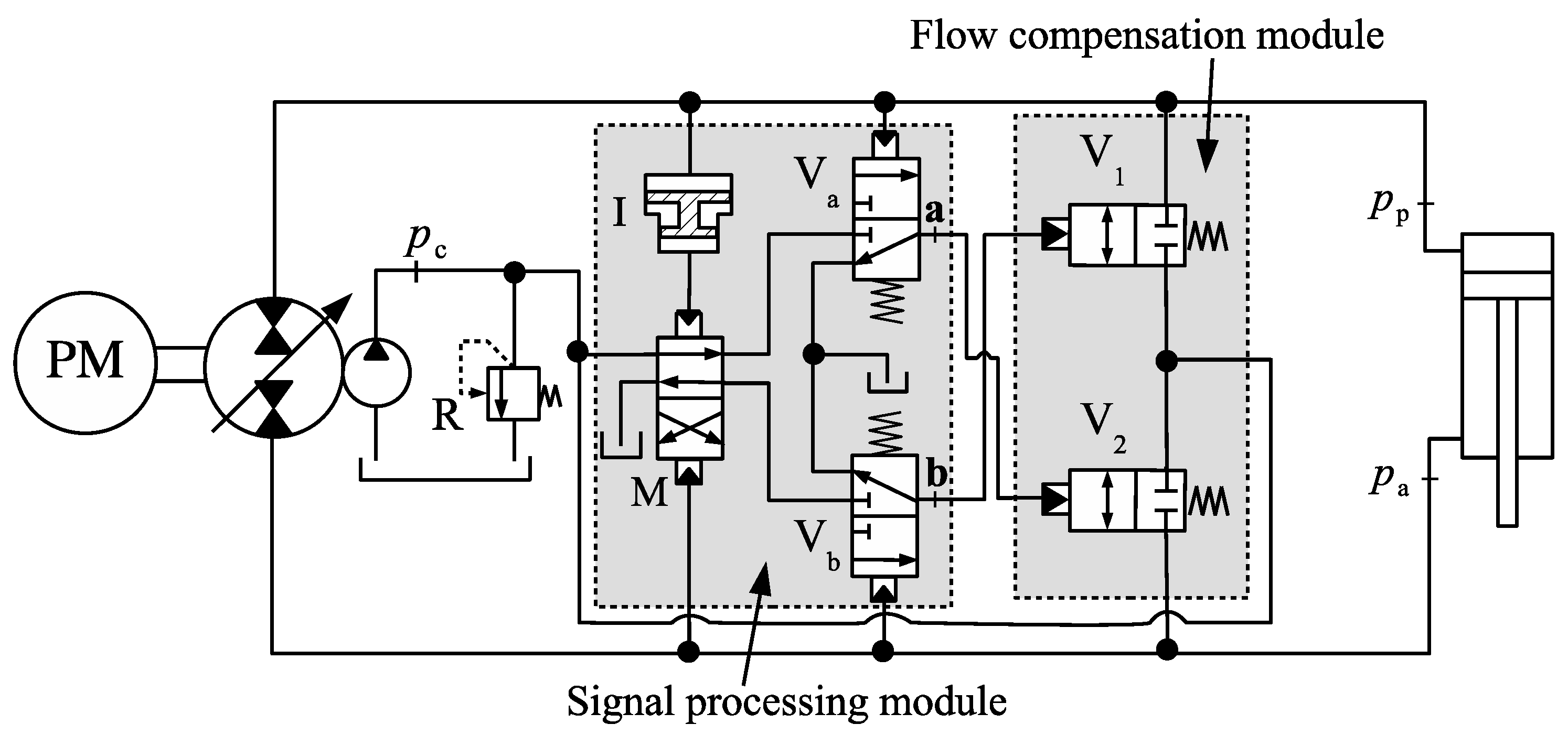
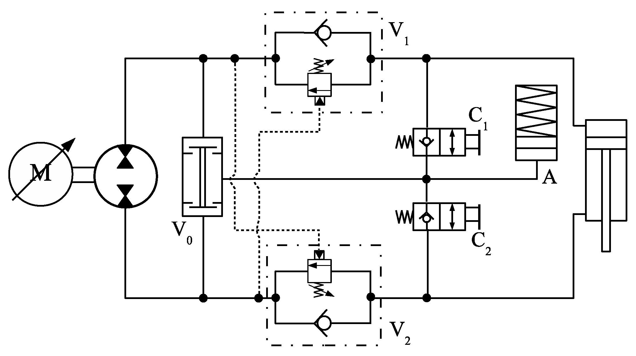
All the circuits so far have shown an oscillatory behaviour in some region of operation [11,14]. Attempts have been made to create a fully functional design by improving on these circuits. Basically, the problem lies in the shifting between cap and rod-side connections to the charge circuit. Although some improvements have been made, we observe that it is impossible to build a stable circuit based on the quadrant division defined in Figure 2b. Recently, a new design was proposed to solve the instability problem [15] by re-defining the operational quadrants according to the net pressure force acting on the cylinder (cylinder force). The proposed DS hydraulic circuit is shown in Figure 8 and requires an amplifier, I, whose gain is given by the piston-to-annulus area ratio of the hydraulic cylinder, . The circuit also separates flow compensation and signal (pressure) processing. As seen in this paper, this recently published design represents the best approach to the differential area problem in single-rod hydrostatic actuators.
Apart from the circuit shown in Figure 8, all solutions introduced so far are unstable at some point. In this paper, we prove that building upon the old concepts is not effective to substantially improve performance. Therefore, the circuit in Figure 8 should be viewed not only as another attempt to create a stable actuator but indeed a starting point for every stable valve-compensated design moving forward.
3. Flow Commutation in Valve-Compensated Circuits
We have seen that single-rod hydrostatic actuation circuits must contain a means of shifting the connection between the charge circuit and the lines linking the pump to the cylinder. For DS circuits, pressure signals coming from different parts of the circuit are responsible for activating the compensation valves. As an example, the piloted check valves C1 and C2 in Figure 6 need information from pressures , and , simultaneously, when operating in pilot mode, i.e., when valves C1 and C2 are opened by the pressure acting on their pilot ports. On the other hand, they need information from and or from and when operating in normal mode, i.e., when valves C1 and C2 are opened due to the pressure differential between their input and output ports. Likewise, valves V1 and V2 in Figure 4 need information from pressures and independently. Finally, the circuits shown in Figure 7 need information from to connect the charge circuit to the main lines. Out of the three sources of pressure information, , and , only the charge circuit pressure, , can be known in advance.
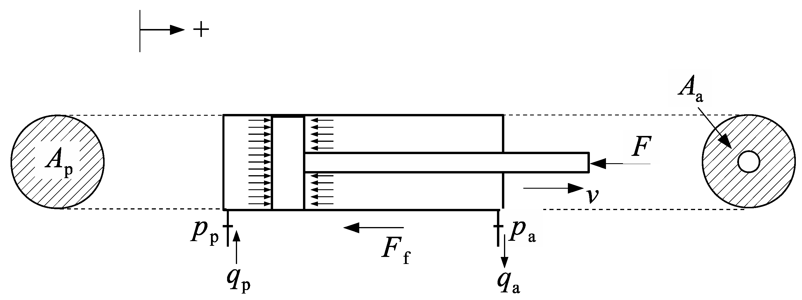
Now, consider a force balance on the single rod cylinder shown in Figure 9
where ; is the resistive friction force and is the combined mass of the piston, rod and load.
From Equation (1), we obtain
where and represents all the forces acting on the cylinder.
The force has been designated cylinder force, in contrast to the external force, , shown in Figure 2b. Indeed, more appropriately defines the quadrant operation of hydrostatic actuators, as seen in the following section.
3.1. New Definition of Operational Quadrants
The proposed division shown in Figure 10 captures the energetic exchanges between pump and cylinder, constituting the only basis on which the terms “motoring mode” and “pumping mode” can be defined. In fact, if we multiply both sides of Equation (2) by the rod-side flow, , we obtain
Observe that the left-hand side of Equation (3) represents the net balance of hydraulic power through the cylinder. Therefore, we see that in the first and third quadrants in Figure 10 (energy flows from the pump to the load) and in the second and fourth quadrants in Figure 10 (energy flows from the load to the circuit). This representation is far better than the versus diagram shown in Figure 2b, which does not guarantee that the geometrically bounded quadrants coincide with the mode of operation (see, for example, Reference [14]).
The division between pumping and motoring mode has also been done in terms of the signs of the pressure differential across the pump, , and the pump flow, , defined as positive when circulating from rod-side to cap-side, through the pump. In this sense, it has been stated that pumping mode occurs when the signs of and coincide, otherwise the circuit operates in motoring mode. Such division would naturally attribute a special meaning for . For instance, the external load, , for which has been identified as the “critical load”, [11,14]. This so-called “critical load” has then been used to establish limits for pumping and motoring quadrants and, since is different for different circuit configurations, the quadrant division can become complex, such as the one shown in Figure 11 where four critical loads, through , define two distinct critical zones for the circuit shown in Figure 6.
The presence of critical zones plus the non-geometrical “operational quadrants” make the whole diagram in Figure 11 extremely difficult to comprehend. This is particularly discouraging if we add the fact that the critical zones are directly affected by friction forces and other energy losses. Since friction is a complex and difficult phenomenon to be precisely modelled, it turns out that we cannot know for sure the location of the borderlines between pumping and motoring regions. On the other hand, the division defined in Figure 10 is precise, where each operational quadrant coincides with a geometrical quadrant on the versus plane.
3.2. Instability during Flow Commutation
The causes of undesired oscillations in single rod actuators have been assigned to several factors. For instance, it has been reported that the cylinder velocity is a discontinuous function of the operational quadrant and, as a result, whenever the operation shifts from pumping to motoring, oscillations are likely to take place [16]. We state that the cause of oscillations in the circuit is the misbehaviour of the compensation valves due to insufficient or incorrect control information. This is illustrated next.
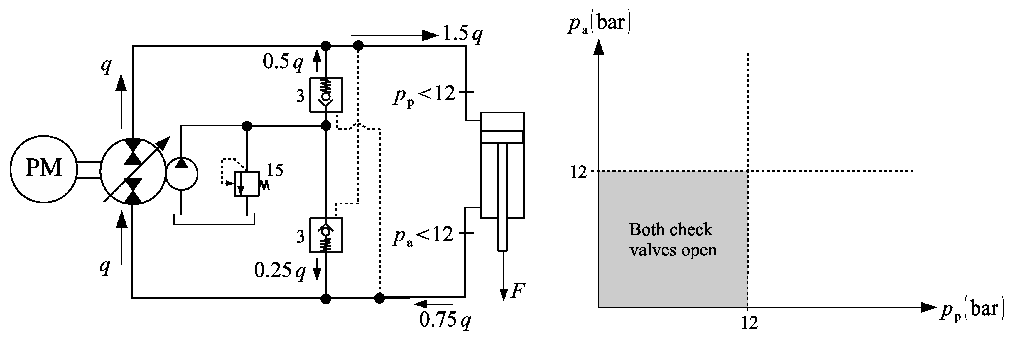
Consider as an example the circuit shown in Figure 6 and reproduced in Figure 12. The numbers near the valves represent their cracking pressures. The graph on the right shows the regions where the check valves open by the action of the pressure differential (not the pilot pressure). Clearly, if the cracking pressures are 3 bar and the charge circuit is kept at 15 bar, the check valves open when the pressures at their opposite ports become smaller than 12 bar, as indicated by the grey area in the versus diagram.
Suppose that the pump delivers a flow, , into the cylinder as its rod pushes an assistive load, . Now, consider that at some point during the cylinder extension, the force, , becomes very low, causing the pressures at the cap and rod-sides to drop down to values lower than 12 bar. Under this circumstance, there is no change in the operation mode. However, both check valves open, causing the cylinder to accelerate downwards, demanding a higher flow at the cap-side (). On the other hand, the flow coming from the rod-side () needs to be matched to enter the pump. Again, the charge flow supplies the needed share (). During this time and as long as the load remains low, the cylinder is not controlled by the pump. If, eventually, one of the check valve closes, a sudden variation on the cylinder velocity occurs. This is basically the cause of the observed oscillatory behaviour at low loads.
In what follows, we study the flow distribution between the charge circuit and the cylinder for the different designs introduced in Section 2.
4. Flow Compensation Using Pilot-Operated Check Valves
Consider the check valves C1 and C2 in the circuit shown in Figure 6, reproduced in Figure 13. Let us disregard conduit losses in the circuit and study the behaviour of these valves when subjected to the pilot pressures (valve C2) and (valve C1). Assuming an on-off operation for the check valves, it is possible to write that valve C2 opens when [14]
where and are the check valve pilot ratio and cracking pressure, respectively. Likewise, the following conditions must be fulfilled for the opening of valve C1
Using inequalities (6) and (7), it is possible to study how valves C1 and C2 change their status according to the pressures on the cap- and rod-sides of the cylinder. We do this in the following section.
Rearranging Equations (4) and (5), one can obtain the following conditions for the opening of valves C1 and C2 in pilot operation (inequalities 1P and 2P, respectively) and normal operation (inequalities 1N and 2N, respectively)
As an example, assume that , and . Inserting these values into (6), we obtain
Figure 14 shows inequalities (7) in a graphical manner. In the figure, we identify three regions; two of these regions represent the ideal circuit status where only one valve is open. The other regions, marked as A1, A2 and B, indicate instabilities in the circuit, where both valves are open or closed at the same time. According to (7), valve C1 is open in the region above line 1P and to the left of line 1N. On the other hand, valve C2 is open in the region below lines 2P and 2N.
In the passage between quadrants I and II as well as between quadrants III and IV, the pressures and are reduced. From Figure 14, we observe that, in this case, it is easy to reach region B, where both valves, C1 and C2, are simultaneously closed. The situation is also unfavourable when the cap and rod-side pressures are high, causing both valves to open. This may well be the case during motoring quadrants if a higher than usual pressure is chosen for the charge circuit.
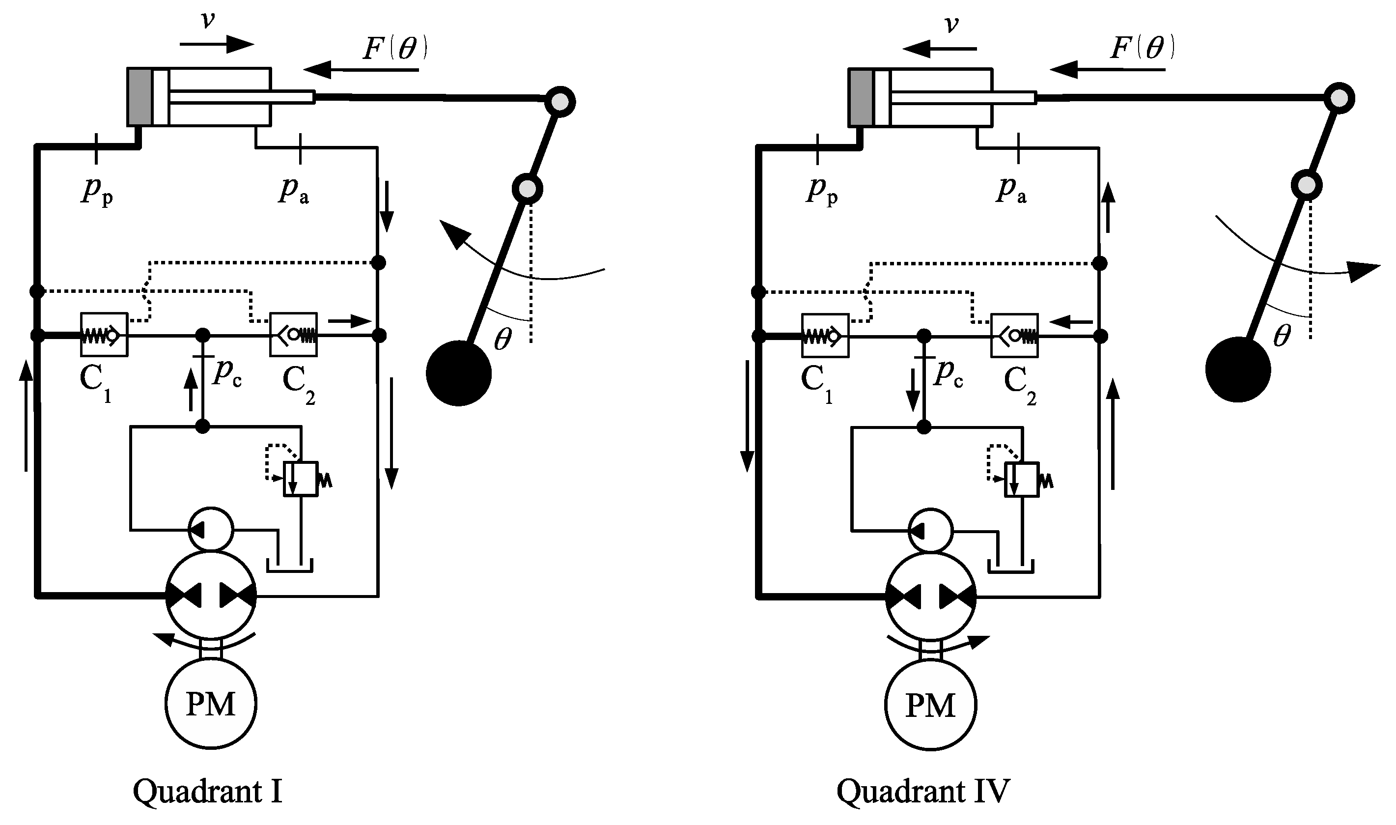
Figure 15 shows an example of a circuit operating a load in the first and fourth quadrants. First, the cylinder extends against a resistive force, , as the pendulum mass moves to the left (first quadrant). When the cylinder reaches the end of its stroke, the mass returns to its original position, and the force, , becomes assistive (fourth quadrant). Given that varies from zero to a maximum, the cap-side pressure, , also changes between zero and a maximum.
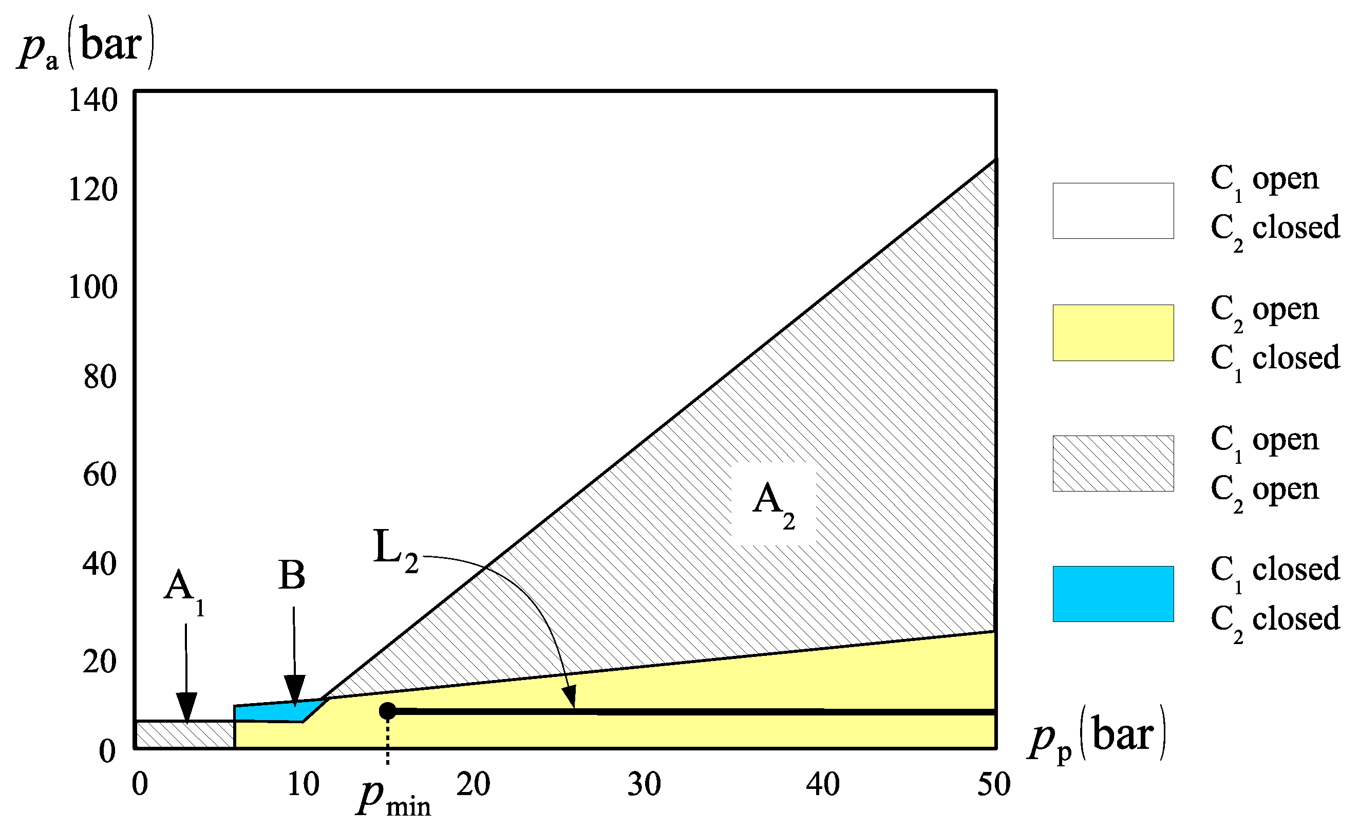
The situation represented by Figure 15 implies that valve C1 must remain closed while C2 is open during the whole operation. However, given that continuously changes from zero to a maximum value, this ideal situation is not likely to happen. Figure 16 shows three possible paths to be taken by the pressure, , when the same settings used for the diagram in Figure 14 are applied. Depending on the charge pressure value (note that during operation), the cap-side pressure might change along lines L1, L2 or L3. In the first case, represented by line L1, region A1 is crossed and, for a moment in time, both valves C1 and C2 are simultaneously open. If line L2 is chosen, region B is reached and, for a moment, valves C1 and C2 are closed. If we choose to increase the charge pressure even more (line L3), we cross region A2, where C1 and C2 are open. In summary, there is absolutely no way to obtain a sound operation of the circuit in Figure 15. This circuit does not work anyway, regardless of how you operate the valves; one way or another, they fail.
Although it is not possible to completely eliminate the zones where valves C1 and C2 do not operate as expected, we might still be able to improve the circuit performance. Figure 17 shows one solution to shift the operation zone to the right during the first and fourth quadrants [14].
With reference to Figure 17, the role of the counterbalance valves, V1 and V2, is to set a minimum pressure at both sides of the cylinder, below which no motion takes place. This way, we can shift the operation zone to the right. Take, for example, line L2 in Figure 16, represented again in Figure 18. If the minimum cap-side pressure is set to 15 bar, the circuit operates along the zone where C1 is closed and C2 is open, which fulfils the requirement for a sound circuit operation. The minimum cap-side pressure is set by sensing the rod-side pressure, . Since the cylinder will not move before the opening of valves V1 and V2 (Figure 17), we can write that . Thus, when reaches a minimum value, valve V2 opens, unblocking the flow coming from the rod-side during the first quadrant. A similar situation happens in the fourth quadrant. Figure 18 shows the operation in the first and fourth quadrants of the circuit shown in Figure 17.
It is worth noting that even the circuit in Figure 17 can become unstable if the charge pressure is increased. For instance, the same inferior limit for the cap-side pressure, , would not have worked for line L3 in Figure 16. In that case, should increase to escape the region where both valves, C1 and C2, are open. Furthermore, depending on the value of the external force, , the cylinder may not complete its stroke during the fourth quadrant of operation. In fact, at some point during the pendulum swing in Figure 15, the external force, , becomes low enough to render . As a result, the piston stops before completing its stroke.
5. Flow Compensation Using Directional Valves
We have seen that flow compensation using check valves creates regions where both sides of the cylinder are either closed or simultaneously connected to the charge circuit. In this section, we analyse the case where two 2 × 2 directional valves are used (see Figure 4). This configuration is an extended version of the circuit shown in Figure 2a. Figure 4 is now represented by Figure 19, which includes the possibility of a different charge pressure, , and a moving mass attached to the cylinder rod, as in Figure 15.
In Figure 19, we represent the cracking pressures of valves V1 and V2 as and , respectively. The following conditions must be fulfilled for each valve to be activated
Figure 20 shows a graphical representation of inequalities (8) where we have assumed that the two valves, V1 and V2, are identical (). We also consider that , a typical cracking pressure for this type of valve. Lines L1 and L2 represent two possible variations of the cap-side pressure, , as the circuit operates between the first and fourth quadrants. Note that the only operation path acceptable is the one along line L1, crossing a large region where valve V2 is open, connecting the rod-side to the charge circuit, and valve V1 is closed. However, for smaller values of , both valves are closed. In the first quadrant, the cylinder extends anyway because of the check valve C2, connecting the rod-side to the charge circuit. In the fourth quadrant, since valve C2 remains closed, the cylinder will stop moving at point A, where the cap-side pressure reaches 6 bar. As a result, the weight will move in a full swing to the left (first quadrant) but will stop before returning to the upright position on its way back (fourth quadrant).
Figure 21 shows another circuit using a single 2 × 2 directional valve [17]. Following the idea introduced in Reference [18], two in-line piloted check valves, I1 and I2, are placed at the cap and rod-side of the cylinders, dividing the pump-cylinder lines into two parts. The inline check-valve concept resembles the counterbalance valves of the circuit shown in Figure 17.
The circuit in Figure 21 was designed to operate in pumping mode only. Instead of a charge circuit, two anti-cavitation valves, C1 and C2, and a relief valve, R, were added to keep the lowest circuit pressure within acceptable levels. First quadrant operation only requires that the cap-side pressure becomes high enough to open valve I2. As soon as the cylinder starts extending, the low pressure created at the rod-side opens the anti-cavitation valve C2. In the third quadrant, the 2 × 2 valve, V, is activated by the pressure differential between the pump ports, and , so that the cap-side pressure is set by the relief valve, R, when the following inequality is satisfied
where is the cracking pressure of valve V.
Another circuit [19], similar to the one in Figure 21, makes use of counterbalance valves instead of inline piloted-check valves, as shown in Figure 22. The externally controlled valve, V0, replaces valves V and R in Figure 21, to make third quadrant operation possible. Although there is practically no conceptual difference between the designs in Figure 21 and Figure 22, we note that the circuit in Figure 22 allows for motoring operation in the second quadrant. In that case, the counterbalance valve V2 opens directly by the rod-side pressure. According to our previous classification, this circuit is partially motored, since it cannot operate in the fourth quadrant.
6. Flow Compensation Using Single-Directional Valve
We have seen in the solutions presented so far that each compensation valve used the pressure at the opposite hydraulic line as a triggering signal to connect the charge circuit to the cylinder. However, if we look at the circuits in Figure 7, we see that we might as well use the pressure differential, , to decide on which line needs to be connected to the charge circuit. In fact, in every single-rod actuator, the rod-side of the cylinder needs to connect to the charge circuit in quadrants I and IV, whereas the cap-side of the cylinder needs to connect to the charge circuit in quadrants II and III.
Assuming an on-off operation of the 3 × 3 directional valves in Figure 7a,b, the pressures, and , needed to connect the cap and rod sides of the cylinder to the charge circuit must satisfy the following inequalities
Figure 23 shows the graphic representation of the inequalities (10) for . Because of the fact that only one valve is present, we simply mention the cylinder side that is connected to the charge circuit in the diagram. In the figure, we note the existence of a region where the valve spool is centred. We also see two possible paths, L1 and L2, along the first and fourth quadrants. In both cases, there is a region where communication between the charge circuit and the cylinder is either blocked (Figure 23a) or partially opened (Figure 23b). Such region has been called “critical” [11] and, apparently, should be minimized for a smooth circuit operation. As seen in this paper, although such condition improves the circuit performance, the instabilities are not completely eliminated even when the critical region is reduced to zero.
Aiming at reducing the critical region, a series of hydraulic circuits have been patented [20]. One of the proposed circuits uses different cracking pressures and , on either sides of the 3 × 3 valve of the circuit shown in Figure 7a to somehow balance out the differential cylinder areas. Thus, considering again the inequalities (10), we can make and then :
Note that the equivalent choice and would have produced the following inequalities instead
Figure 24 represents the inequalities (11) and (12) for and . We see that the choice is better than the choice . However, none of these choices eliminate the critical region.
Figure 25 shows one circuit where a logic hydraulic valve (AND) was used as the compensation element [4]. Apart from the counterbalance valves, the circuit shown in Figure 25 is functionally identical to the circuits in Figure 7; the difference being the replacement of the 3 × 3 directional valves with the logic valve V0, which does not have either a central position or a spring element whose cracking force needs to be overcome.
Figure 26 shows the flow compensation diagram for the circuit shown in Figure 25, obtained by making in inequalities (10). No critical region exists, however, as duly explained in Section 7, as operation along line L1 is poor. In fact, as the circuit operates between points A and B, the rod-side is disconnected from the charge circuit and, since we do not know for sure where the borderline between quadrants II and I is located, it is possible to have the rod-side disconnected from the charge circuit in the first quadrant with the risk of pump starvation. In fact, the only guarantee of a smooth operation with no ambiguous shift between quadrants would be along line L2 in Figure 26, for which the rod-side pressure, , is zero. This would be achieved by connecting the compensation valve to the tank, as opposed to the accumulator in Figure 25. However, such arrangement would result in a considerably low rod-side pressure, with an inherent risk of cavitation.
We have seen so far that all the attempts to produce an oscillation-free single-rod actuator has not been fully satisfactory. In fact, there is one piece of the puzzle that is lacking for a successful solution. There is a need for a new approach to correctly define the operational quadrants. The theory behind this approach has been disclosed in References [15,21] and is discussed next.
7. Solving the Flow Distribution Problem
The circuit shown in Figure 25 showed a great advantage when compared to the circuits in Figure 7, eliminating the “critical region” where flow compensation is imprecise. However, all previous circuits have one negative characteristic in common: All of them are based on incorrect information when it comes to sensing the right operational quadrant. This happens due to an incorrect definition of the operational quadrants, founded on poorly defined quadrant boundaries. Thus, using a correct operational quadrant definition is of paramount importance. In this respect, the division shown in Figure 10 should be our starting point. Based on that division, we argue that:
- (a)
- Neither the individual values of pressures and nor the pressure differential can be correctly used as an indicator for the operational quadrant;
- (b)
- The only correct indicator for the operational quadrant is the cylinder force, .
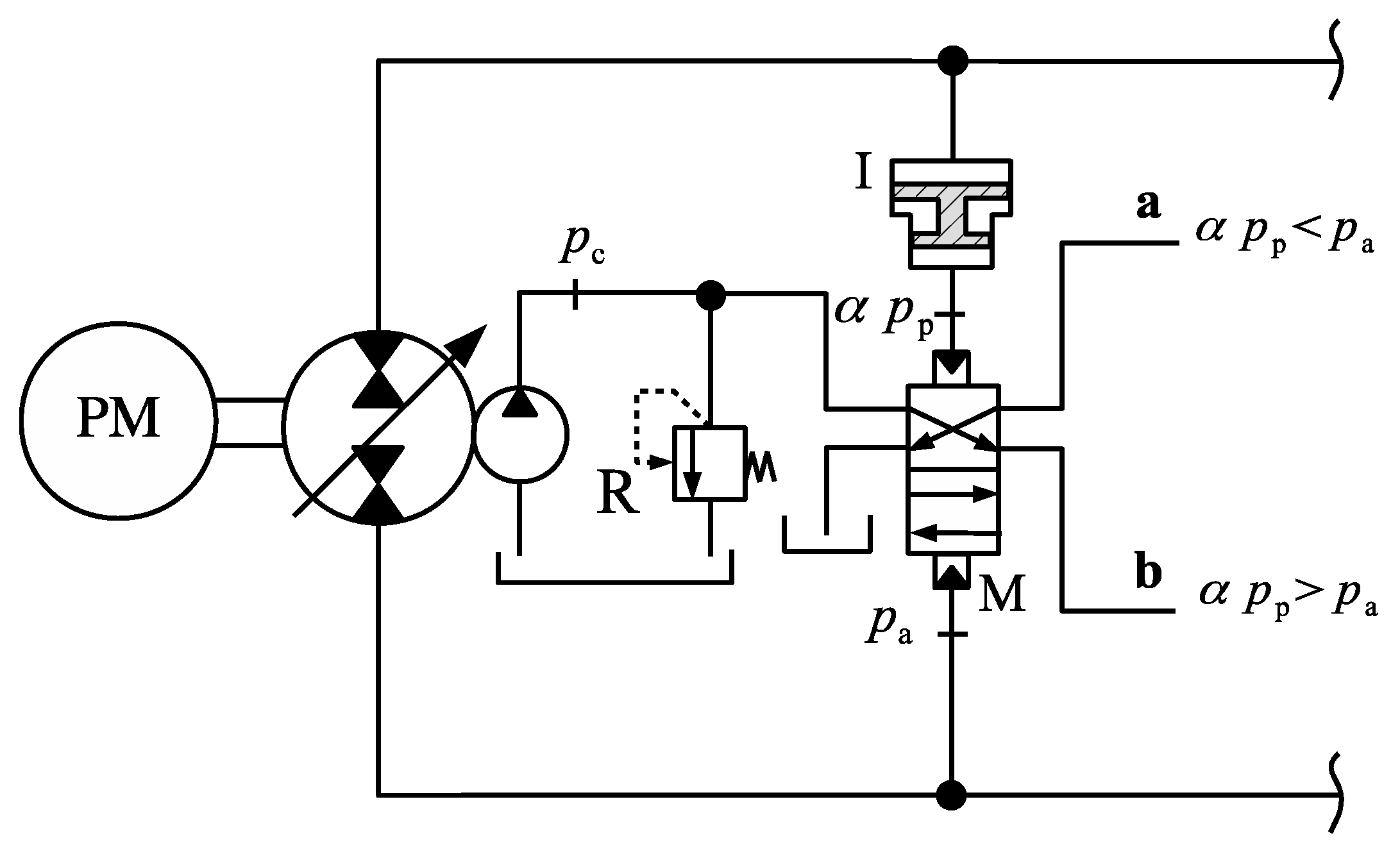
Given the arguments above, we started building a fully functional circuit right from the correct triggering signal for the compensation valve (or valves). Figure 27 shows one possible triggering circuit that uses a hydraulic intensifier, I, and a memory type 4 × 2 valve, M.
With regards to Figure 27, the amplified pressure signal coming from the intensifier, , is compared to the rod-side pressure, . If , the pressure at port a is set to the charge circuit pressure, , while the pressure at port b is set to zero. The opposite happens when .
Although we could use the pressure signals in ports a and b to determine the connections between cylinder and charge circuit, we observe that the memory valve, M, cannot give the correct information when both cap and rod-side pressures are zero. This means that at the beginning, when , M might be incorrectly positioned and therefore unable to indicate the right operational quadrant. One solution to this problem is shown in Figure 28, where two 3 × 2 directional valves are placed between the memory output and the circuit lines. Note that now, port a is pressurized only if the memory is correctly set () and the cap-side pressure, , becomes sufficiently high to overcome the cracking pressure of valve, Va, otherwise the pressure at port a is set to zero. A similar reasoning can be applied to port b.
The circuit shown in Figure 28 is the core of what can be seen as the general solution to the single-rod actuator problem. All that is needed now is to add the right compensation valves. These, in turn, must be placed in the circuit in such a way that when port a is pressurized (first or fourth quadrants), the rod-side of the cylinder connects to the charge circuit. Likewise, when port b is pressurized, the cap-side of the cylinder is connected to the charge circuit. Note that it is impossible to have both ports a and b pressurized at the same time. Figure 8 shows one oscillation-free solution for single-rod actuators. The cracking pressures of the 2 × 2 valves, V1 and V2, must be smaller than the charge pressure, , so that they are fully open as soon as the triggering pressure signal is received. Although it is not shown in the figure, there is absolutely no need for the charge circuit to feed both the compensation valves and the signal circuit simultaneously, as they work independently from one another.
Figure 29 shows how the status of valves V1 and V2 in Figure 8 change with the cap and rod-side pressures. For instance, following line L, suppose that the load is initially pulling the cylinder rod in such a way that (operating point 1). In this case, we have that and , which means that the actuator operates in the second quadrant (Figure 10). Valve V1 then opens up, connecting the cap-side to the charge circuit while valve V2 remains closed, as expected. As the cap-side pressure rises past point 2, becomes positive and the circuit enters into pumping mode. As a result, valve V1 closes while valve V2 opens, as is expected for first quadrant operation.
Figure 29 also helps us understand why the operation along line L1 in Figure 26 could not be altogether smooth. Observe that line L in Figure 29 coincides with line L1 in Figure 26. Thus, if we follow line L in Figure 29, we see that, in the stretch between operating points 2 and 3, we would have had the cap-side connected to the charge circuit in Figure 26 (note the dashed line is the same line dividing the two regions in Figure 26). However, the cap-side connection between points 2 and 3 would have happened in the first quadrant, causing the circuit to misbehave. This is why eliminating the “critical region”, as defined in Section 6, does not solve the problem.
The quadrant division proposed in Figure 10, which led to the solution shown in Figure 8, has been provisionally patented [21] and a similar circuit using electro-valves has been successfully experimented [15]. The results obtained were so encouraging that we truly believe that no other attempt to solve the differential area problem will be necessary any longer.
8. Conclusions
In this paper, we have analysed the latest solutions to the problem of differential flows in single-rod hydrostatic actuators. The conclusion we have arrived at is that the root of the problem lies on the basic definition of pumping and motoring quadrants. To this end, we have shown that every previous attempt produced circuits with limited stability that cannot be used with confidence in real-life applications. We further showed that a new circuit design, based on a correct definition of pumping and motoring quadrants, has come to solve the compensation flow instabilities and provide the basis for the development of commercially viable circuits.
Author Contributions
G.K.C. contributed in the development of the concepts, analyses of designs, formulation of the problem, preparation and visualization of data, writing of the original draft. N.S. contributed in the discussions leading to concepts, reviewing of results and editing the paper, project administration and funding acquisition.
Funding
This research was funded by NSERC (Natural Sciences and Engineering Research Council of Canada). Grant number: RGPIN 121353-2013.
Conflicts of Interest
The authors declare no conflict of interest.
References
- Merritt, H.E. Hydraulic Control Systems; John Wiley & Sons: New York, NY, USA, 1967. [Google Scholar]
- Frankenfield, T.C. Using Industrial Hydraulics, 1st ed.; Hydraulics and Pneumatics Magazine: Cleveland, OH, USA, 1984; pp. 6-24–6-25. [Google Scholar]
- Hewett, A.J. Hydraulic Circuit Flow Control. U.S. Patent 5,329,767, 19 July 1994. [Google Scholar]
- Altare, G.; Vacca, A. A design solution for efficient and compact electro-hydraulic actuators. Procedia Eng. 2015, 106, 8–16. [Google Scholar] [CrossRef]
- Costa, G.K.; Sepehri, N. Hydrostatic Transmissions and Actuators—Operation, Modelling and Applications, 1st ed.; John Wiley & Sons: Chichester, UK, 2015. [Google Scholar]
- Pourmovahed, A.; Beachley, N.H.; Fronczak, F.J. Modeling of a hydraulic energy regeneration system—Part 1: Analytical treatment. Trans. ASME 1992, 114, 155–159. [Google Scholar] [CrossRef]
- Wendel, G.R. Regenerative hydraulic systems for increased efficiency. In Proceedings of the 48th National Conference on Fluid Power, Chicago, IL, USA, 4–6 April 2000; pp. 199–206. [Google Scholar]
- Rahmfeld, R.; Ivantysynova, M. Energy saving hydraulic actuators for mobile machines. In Proceedings of the 1st Bratislavian Fluid Power Symposium, Casta Pila, Slovakia, 2–3 June 1998; pp. 47–57. [Google Scholar]
- Rahmfeld, R.; Ivantysynova, M. Displacement controlled linear actuator with differential cylinder-a way to save primary energy in mobile machines. In Proceedings of the 5th International Conference on Fluid Power Transmission and Control—ICFP, Hangzhou, China, 4–5 April 2001; pp. 296–301. [Google Scholar]
- Zimmerman, J.D.; Ivantysynova, M. Reduction of engine and cooling power by displacement control. In Proceedings of the 6th FPNI—PhD Symposium, West Lafayette, IN, USA, 15–19 June 2010; pp. 339–352. [Google Scholar]
- Wang, L.; Book, W.J.; Huggins, J.D. A Hydraulic Circuit for Single Rod Cylinder. J. Dyn. Syst. Meas. Control 2012, 134, 011019. [Google Scholar] [CrossRef]
- Caliskan, H.; Balkan, T.; Platin, E.B. A Complete Analysis and a Novel Solution for Instability in Pump Controlled Asymmetric Actuators. J. Dyn. Syst. Meas. Control 2015, 137, 091008. [Google Scholar] [CrossRef]
- Yuan, H.; Shang, Y.; Vukovic, M.; Shuai, W.U.; Murrenhoff, H.; Jiao, Z. Characteristics of energy efficient switched hydraulic systems. JFPS Int. J. Fluid Power Syst. 2014, 8, 90–98. [Google Scholar] [CrossRef]
- Imam, A.; Rafiq, M.; Jalayeri, E.; Sepehri, N. Design, Implementation and Evaluation of a Pump-Controlled Circuit for Single Rod Actuators. Actuators 2017, 6, 10. [Google Scholar] [CrossRef]
- Costa, G.K.; Sepehri, N. Four-Quadrant Analysis and System Design for Single-Rod Hydrostatic Actuators. J. Dyn. Syst. Meas. Control 2019, 141, 1–15. [Google Scholar] [CrossRef]
- Williamson, C.; Ivantysynova, M. Pump mode prediction for four-quadrant velocity control of valveless hydraulic actuators. In Proceedings of the 7th JFPS International Symposium on Fluid Power (TOYAMA 2008), Toyama, Japan, 15–18 September 2008; pp. 323–328. [Google Scholar]
- Parker-Hannifin Compact EHA, Catalog HY22-3101E 7/13. Available online: https://www.parker.com/Literature/Hydraulic%20Pump%20Division/Oildyne%20EHA/Compact-EHA-Catalog-HY22-3101E-7-13.pdf (accessed on 28 May 2019).
- Wendel, G.R. Hydraulic system configurations for improved efficiency. In Proceedings of the 49th National Conference on Fluid Power, Las Vegas, NV, USA, 19–21 March 2002; pp. 567–573. [Google Scholar]
- Jalayeri, E. Design and Experimental Evaluations of a Pump-Controlled Hydraulic Circuit. Ph.D. Thesis, University of Manitoba, Winnipeg, MB, Canada, 2016. [Google Scholar]
- Imam, A.; Sepehri, N. Pump-Controlled Hydraulic Circuits for Operating a Differential Hydraulic Actuator. U.S. Patent 15/815,181, 20 September 2018. [Google Scholar]
- Costa, G.K.; Sepehri, N. Logic-Controlled Flow Compensation Circuit for Operating Single-Rod Hydrostatic Actuators. U.S. Patent 8,701,400, 22 March 2019. [Google Scholar]
Figure 1.
The problem of unmatched flows in single-rod actuators: (a) pump starvation during extension; (b) cap-side pump overflow during retraction.
Figure 1.
The problem of unmatched flows in single-rod actuators: (a) pump starvation during extension; (b) cap-side pump overflow during retraction.

Figure 2.
(a) Frankenfield’s circuit; (b) external force versus velocity quadrant representation.

Figure 3.
Four quadrant operation of Frankenfield’s circuit.

Figure 4.
Alternative circuit using two 2 × 2 valves.

Figure 5.
Four-quadrant operation of Hewett’s circuit.

Figure 6.
Circuit with piloted check valves.

Figure 7.
Circuits using 3 × 3 directional valves: (a) circuit proposed in Reference [11]; (b) circuit proposed in Reference [12].

Figure 8.
Circuit with signal processing and flow compensation modules [15].
Figure 8.
Circuit with signal processing and flow compensation modules [15].

Figure 9.
Single-rod actuator.

Figure 10.
Operational quadrants.

Figure 11.
Critical zones and quadrant division [14].
Figure 11.
Critical zones and quadrant division [14].

Figure 12.
Example of compensation valves misbehaviour.

Figure 13.
Pressures within the circuit using pilot-operated check valves.

Figure 14.
Status of check valves C1 and C2 as functions of the cap and rod-side pressures.

Figure 15.
External force on the cylinder rod (first and fourth quadrants).

Figure 16.
Check valves status at first and fourth quadrant operation.

Figure 17.
Counterbalance valves in the circuit.

Figure 18.
Operation zone shifting during first and fourth quadrants.

Figure 19.
Circuit with two 2 × 2 compensation valves and external force on the cylinder rod (first and fourth quadrants).
Figure 19.
Circuit with two 2 × 2 compensation valves and external force on the cylinder rod (first and fourth quadrants).

Figure 20.
Status of the directional valves V1 and V2 for different circuit pressures.

Figure 21.
Circuit with 2 × 2 compensation valve and inline check-valves.

Figure 22.
Addition of inline check-valves.

Figure 23.
Connections between the cylinder sides and the charge circuit: (a) closed centred circuit (Figure 7a); (b) open centred circuit (Figure 7b).

Figure 24.
Circuit connections for: (a) ; (b) .

Figure 25.
Circuit with a logic valve.

Figure 26.
Logic valve circuit connections.

Figure 27.
Signal generator for correctly determining the operation quadrant.

Figure 28.
Circuit for triggering the compensation flows.

Figure 29.
Compensation flow connections for the circuit in Figure 8.
Figure 29.
Compensation flow connections for the circuit in Figure 8.

© 2019 by the authors. Licensee MDPI, Basel, Switzerland. This article is an open access article distributed under the terms and conditions of the Creative Commons Attribution (CC BY) license (http://creativecommons.org/licenses/by/4.0/).
Share and Cite
MDPI and ACS Style
Koury Costa, G.; Sepehri, N. A Critical Analysis of Valve-Compensated Hydrostatic Actuators: Qualitative Investigation. Actuators 2019, 8, 59. https://doi.org/10.3390/act8030059
AMA Style
Koury Costa G, Sepehri N. A Critical Analysis of Valve-Compensated Hydrostatic Actuators: Qualitative Investigation. Actuators. 2019; 8(3):59. https://doi.org/10.3390/act8030059
Chicago/Turabian StyleKoury Costa, Gustavo, and Nariman Sepehri. 2019. "A Critical Analysis of Valve-Compensated Hydrostatic Actuators: Qualitative Investigation" Actuators 8, no. 3: 59. https://doi.org/10.3390/act8030059
Note that from the first issue of 2016, this journal uses article numbers instead of page numbers. See further details here.