Comparative Analysis among Single-Stage, Dual-Stage, and Triple-Stage Actuator Systems Applied to a Hard Disk Drive Servo System

Department of Electrical and Electronic Engineering, Dhaka University of Engineering & Technology, Gazipur 1707, Bangladesh
*
Author to whom correspondence should be addressed.
Actuators 2019, 8(3), 65; https://doi.org/10.3390/act8030065
Submission received: 30 June 2019
/
Revised: 17 August 2019
/
Accepted: 22 August 2019
/
Published: 3 September 2019
Abstract
:In modern times, the design and optimization of different actuator systems for controlling a high-precision position control system represent a popular interdisciplinary research area. Initially, only single-stage actuator systems were used to control most of the motion control applications. Currently, dual-stage actuation systems are widely applied to high-precision position control systems such as hard disk drive (HDD) servo systems. In the dual-stage system, a voice coil motor (VCM) actuator is used as the primary stage and a piezoelectric micro-actuator is applied as the secondary stage. However, a dual-stage control architecture does not show significant performance improvements to achieve the next-generation high-capacity HDD servo system. Research continues on how to fabricate a tertiary actuator for a triple-stage HDD servo system. A thermal positioning controller (TPC) actuator is considered promising as the tertiary stage. The triple-stage system aims to achieve greater bandwidth, track density, and disk speed, with minimum sensitivity and greater error minimization. In this work, these three actuation systems with different combinations of proportional plus integral (PI), proportional plus derivative (PD), and proportional plus integral plus derivative (PID) controller, lag-lead controller, lag filter, and inverse lead plus a PI controller were designed and analyzed through simulation to achieve high-precision positioning. The comparative analyses were done on the MATLAB/Simulink simulation platform.
1. Introduction
High precision is an essential part of every positioning control system. To achieve this goal, different actuator stages can be applied to enhance the performances. A hard disk drive (HDD) is a magnetic storage device used to record and retrieve digital information. It is the most important medium for data storage in computers and in data processing systems, where a high-precision control system is a must. Currently, the storage capacity of the HDD servo system has been increased tremendously, being almost eight times more than the previous capacity [1], and it will increase in the near future. Presently, dual-stage actuator systems of HDDs available on the market have a maximum capacity of 10 TB. Many scientists and researchers have already started to propose a modern HDD using a triple-stage actuation system. The main controlling part of an HDD is the magnetic read/write (R/W) head that is used to maintain a fixed position during read and write operations on the HDDs. The R/W head consists of a slider which is attached to the suspension [2]. In a single-stage HDD, only a voice coil motor (VCM) actuator is used for positioning, whereas in a dual-stage system, a VCM actuator is used as the primary stage and a piezoelectric micro-actuator usually made from lead zirconate titanate (PZT) is used as the secondary stage. At this time, a dual-stage actuation (DSA)-based HDD servo system is available on the market. This system performs competently to achieve superior track densities. As a result, the HDD’s data capacity becomes greater by growing the servo bandwidth [3]. Different control techniques have been designed for track following by several scientists over the last few years. Currently, a dual-input single-output (DISO) controller is widely used to analyze the dual-stage actuation of HDD servo systems [4,5]. For a dual-stage controller, the popular configurations are as follows: (a) decoupled master–slave (DMS) configuration, (b) parallel loop configuration, and (c) PQ method [6]. To control a servomechanism in dual-stage HDDs, various methods have already been designed and optimized and are described in the existing literature [7,8,9,10,11]. The decoupled master–slave architecture is explained in [12,13,14,15], the parallel structure is presented in [16,17,18], and the PQ method is described in [19].
In a triple-stage system, the R/W head is controlled by three stages with the help of three actuators installed in different positions of the suspension—a VCM actuator used as the primary stage, a PZT micro-actuator used as the secondary stage, and a thermal positioning controller (TPC) actuator used as the tertiary stage [20,21,22,23,24,25,26]. The TPC actuator composed of heaters in a head slider was designed to develop an actuator with a positioning accuracy of less than 5 nm. To increase the track density, bandwidth, and speed of the future generation HDD, a high-precision servo system is needed where a triple-stage system can be introduced instead of a dual-stage one. Therefore, for future generation HDDs, efficient optimized control techniques will be needed for the triple-stage system. Different control methods have already been developed to control a servo system. A proportional plus integral plus derivative (PID) controller is an ordinary controller technique for controlling any system. In this research, different combinations of PID controllers (such as proportional plus integral (PI), proportional plus derivative (PD), and PID) were used to optimize the outcome. Subsequently, a lag-lead controller for the VCM actuator, a lag filter for the PZT actuator, and an inverse lead plus PI controller for the TPC actuator were designed to reach the goal. Therefore, this work presents the comparative analyses of different control mechanisms for single-stage, dual-stage, and triple-stage actuator systems. The simulation results substantiate the effectiveness of the triple-stage system and the chosen controller for it.
2. Plant Model
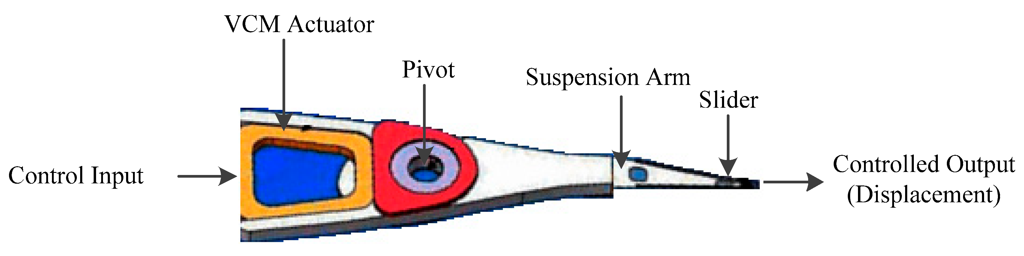
The R/W head of the HDD servo system needs an actuator to control its position on the disk that converts the electrical energy into mechanical energy. It requires a control input (voltage or current) to drive, and the output is the movement of the R/W head. Initially, an HDD servo system was controlled by a VCM-based single-stage actuation system [27,28], where the control input signal was fed to the actuator and this single actuator was driving the R/W head of the HDD servo system, as shown in Figure 1. When only one single actuator is used, the track density was very low and the bandwidth of the closed-loop system was low. As a result, it was a slow head positioning system.
To increase the track density, bandwidth, and speed of the disk, the DSA system was introduced as shown in Figure 2. DSA system consists of a VCM and a PZT actuator [29,30,31]. However, the DSA system still has some limitations which need to be overcome for the next-generation HDD servo system. Therefore, recent research works have proposed a new actuator to be used as the tertiary stage. For the future generation of the HDD servo system, this triple-stage actuator system can be a potential solution [32,33,34,35].
A triple stage HDD servo system using three actuators, as shown in Figure 3, where VCM is used as the primary actuator, PZT is used as the secondary actuator and TPC is used as the tertiary actuator. Three control input signals are provided to these three actuators and then the combined effort of these actuators causes the R/W head to be positioned precisely over the circular tracks.
2.1. VCM Actuator
A VCM comprises a current conveying cylindrical coil of wire put in a radially situated magnetic field produced by permanent magnets. A VCM can be served as a servo motor, which is equipped for moving to an exact and precise angular or linear position according to a position feedback device such as a hall-effect sensor. HDD servo systems use VCM for the positioning of the R/W head through a microcontroller. The frequency response of the VCM actuator can be identified as a double-integrator model which can be expressed as the following form:
where is the gain; is the total number of mechanical resonant modes of VCM actuator. ∑-type denotes the summation of transfer functions of all the mechanical resonances. Each resonant mode is represented by three parameters as follows:
The frequency response of the VCM model used in this work is shown in Figure 4 (obtained from [7]). Here, four resonant modes have been considered. These resonant modes are detrimental to the HDD servo system and can decrease the performance of the system. Therefore, these resonant modes have to be compensated by using resonance compensator.
2.2. PZT Actuator
A piezoelectric micro-actuator made from lead-zirconate-titanate (PZT), usually a push–pull type, is placed very close to the suspension arm. This secondary actuator (PZT actuator) can be modeled in the following mathematical form:
where is the gain; NP is the total number of the mechanical resonant modes of the secondary actuator. Each mode can be expressed as,
The frequency response of a PZT micro-actuator is presented in Figure 5 (obtained from [7]). Here, five resonant modes are identified in the frequency response. Same as the VCM resonant modes, these resonant modes of a PZT micro-actuator also reduces the efficiency of the system. Therefore, like the VCM resonant modes, the effects of these modes also need to be canceled by using an appropriate compensator.
2.3. TPC Actuator
Thermal flying-height control (TFC) sliders can be used to control the head-disk spacing by using thermal actuation and thus is used to expand the bit density of the disk [36,37,38,39]. Utilizing thermal actuators to precisely position the R/W element could be a promising innovation for large scale manufacturing for future HDDs. Using the concept of TFC control, a TPC actuator comprised of heaters in a head slider has been designed to develop an actuator with a positioning accuracy of less than 5 nm. The mathematical model for TPC represented by following formula:
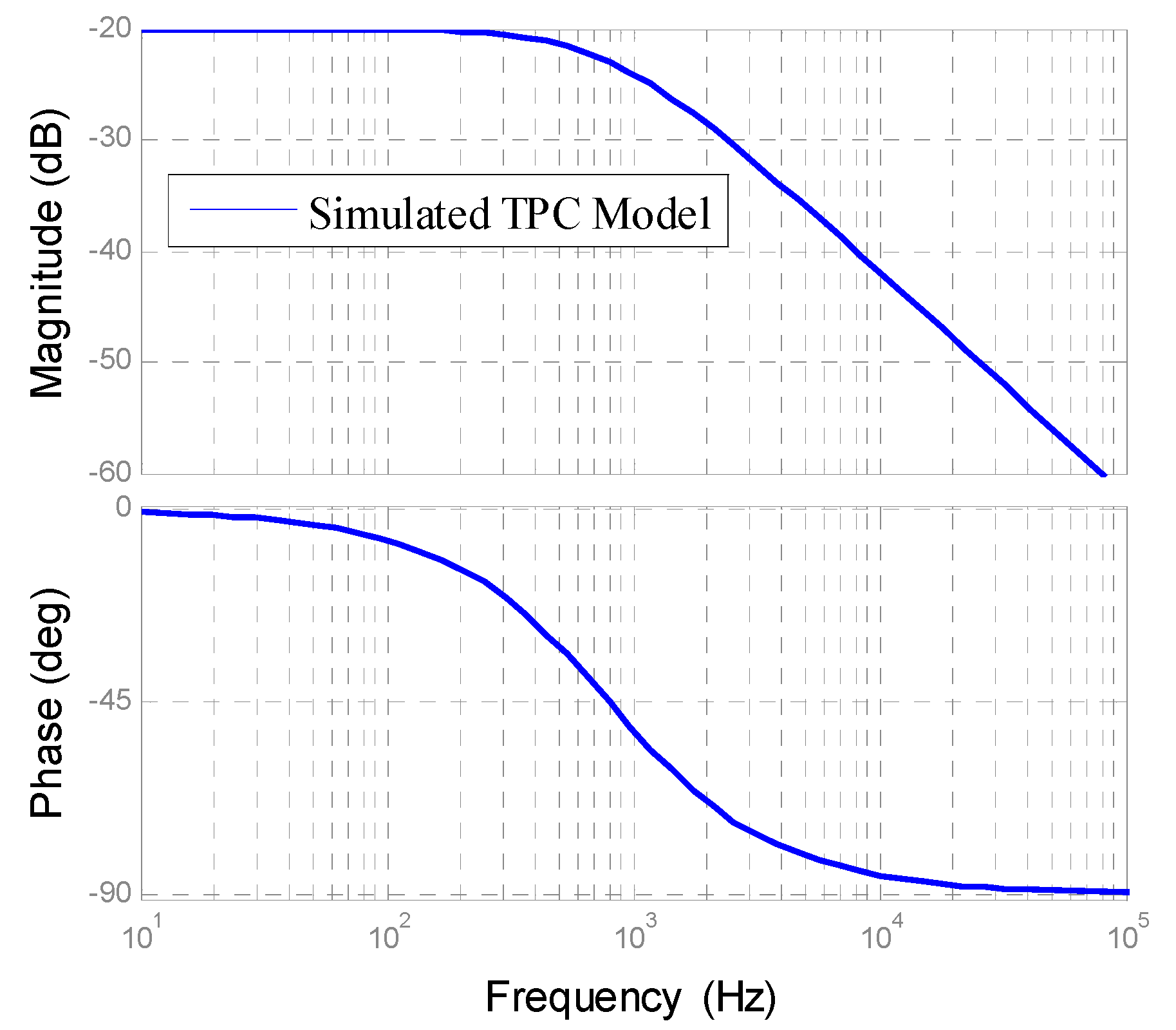
where is the gain and is a constant. In a triple-stage system, TPC actuator is used in the tertiary stage. The frequency response of the tertiary TPC actuator is presented in Figure 6.
The transfer function of the thermal actuator was obtained between the driver to drive with input voltage and the output displacement. According to the theoretical concept, it has been found that a thermal actuator does not exhibit any mechanical resonance. Since no resonant mode was present in this case, there is no need to design a compensator for TPC actuator.
3. Control Architecture
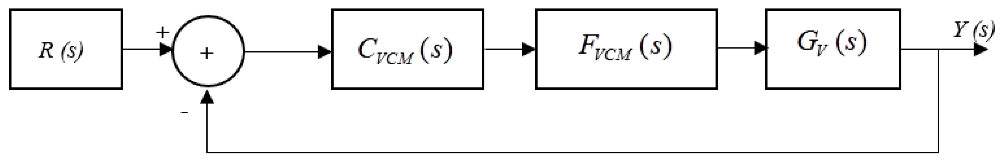
In the beginning, a single-stage actuator system was used to control the HDD servo system shown in Figure 7, where only a VCM actuator was used. This method of single actuation had some limitations, like very low bandwidth and speed. Here is the reference input signal, is the displacement of the R/W head, is the VCM plant model, is the notch filter for VCM, and is the VCM controller.
To improve the performance of an HDD servo system, a secondary actuator is placed between the pivot and slider. This actuator system, known as the dual-stage actuator system, uses the VCM actuator as the primary stage for long-range movement while the secondary PZT actuator is mainly used during track following. The popular dual-stage control architecture is a decoupled master–slave (DMS) architecture as shown in Figure 8. Here is the reference input signal and is the displacement of the R/W head of the dual-stage system, is the plant model, is the notch filter, and is the nominal controller for the PZT actuator. On the other hand, is the plant model, is the notch filter, and is the nominal controller for the VCM actuator. is the feedback path used as the decoupler that feeds the signal to the VCM stage.
Figure 9 shows the control architecture of a decoupled master–slave configuration for a triple-stage HDD servo system. In this architecture, VCM is used as the primary actuator, PZT is used as the secondary actuator and TPC is used as the tertiary actuator.
Here is the reference input signal and is the displacement of the R/W head of triple-stage control architecture. is the plant model and is the nominal controller for TPC actuator. and are used as the decoupler to feed the signal from the previous stage fed to the next stage.
4. Notch Filter
To decrease the effect of different resonant modes of the VCM and PZT actuators, filter circuits have to be used as resonance compensators. In this paper, the notch filter has been used to compensate for the resonant modes. A simple notch filter described by the transfer function as follows can be used to compensate a single resonant mode.
where, ωn1 is the resonance frequency, is the desired damping ratio of the resonant mode. The numerator of F(s) cancels the lightly damped poles of the plant model. The denominator of the plant model can be well damped complex poles at resonance frequency or above. The effects of the changes in phase and amplitude contributed by the denominator on the overall gain and phase margin become negligible.
4.1. Notch Filter for VCM Actuator
The mechanical structure between the VCM actuator and the point to be controlled (head) is flexible leading to various methods of vibration that affects the positioning accuracy. In this case, a notch filter is used as the compensator to compensate the resonant modes of the VCM actuator. From the frequency response of VCM actuator, it is observed that there are a number of resonant modes. Therefore, a notch filter is used to reduce the gain at certain resonance frequencies. Figure 10 and Figure 11 illustrate the application of the notch filter in VCM actuator. After compensating the resonant modes through notch filter, the VCM actuator model is almost similar to a double integrator model. From the following figures, clear attenuation of resonant modes of VCM actuator can be observed.
4.2. Notch Filter for PZT Actuator
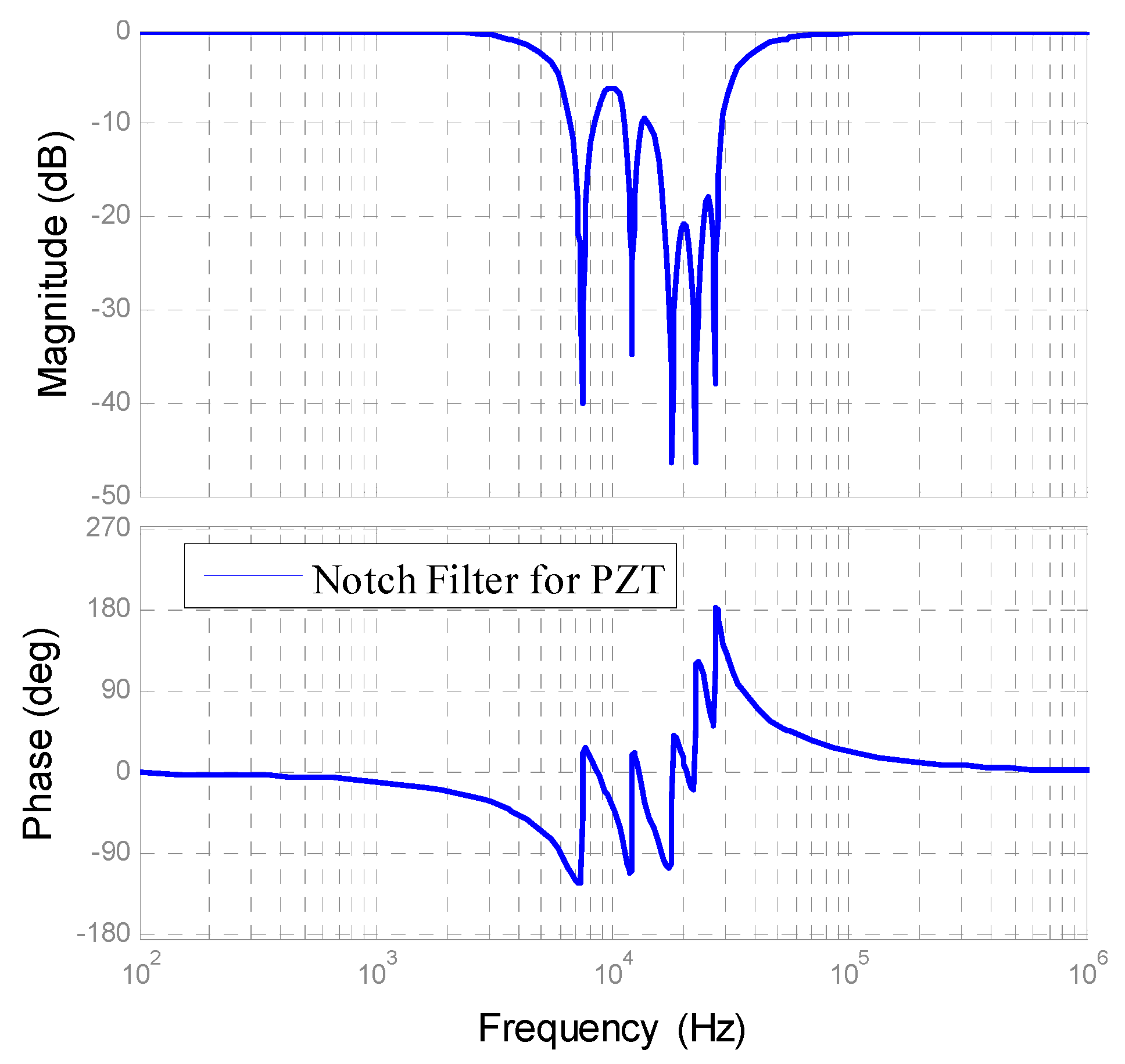
Many resonant modes are also observed in the frequency response of the PZT actuator. Therefore, a notch filter was used to gain stabilization for each resonant mode of the PZT actuator. The complex PZT model has five resonant modes. Figure 12 shows the frequency response of a complicated PZT model with a notch filter, and Figure 13 presents the frequency response of notch filter for PZT model. From these two figures, it is clearly observed that the notch filter can effectively compensate for the resonant modes of PZT actuators.
5. Controller Design for Different Actuation System
A controller is employed in a servo system to precisely obtain the desired output. A controller is defined as the optimized controller when rise time, settling time, percentage overshoot, bandwidth, phase margin, and gain margin are within satisfactory limits. In this work, by observing the simulation results of various control combinations, the optimized proposed controller is selected with considering the above-mentioned criteria.
5.1. PI Controller
A controller used to remove the steady-state error from a system response is known as a proportional plus integral (PI) controller. The transfer function of the PI controller can be expressed as:
where P is the proportional gain and I is the integral gain parameter.
5.2. PD Controller
An ideal proportional plus derivative (PD) controller is used to minimize the transient error of a system response. The PD controller can be expressed as:
where P is the proportional gain, D is the derivative gain parameter, and N is the filter coefficient in the derivative filter.
5.3. PID Controller
To obtain the improvement of both the steady-state error and transient response, the PI controller and the PD controller can be combined, which is known as proportional plus integral plus derivative (PID) controller. The PID controller can be expressed as follows.
where P is the proportional gain, I is the integral gain, D is the derivative gain parameter, and N is the filter coefficient in the derivative filter. The tuning method is used here to determine the optimized value of P, I, D, and N by using MATLAB simulation.
5.4. Lag-Lead Compensator for VCM Loop
A lag-lead compensator is widely used in HDD servo systems to control the VCM actuator [40,41,42]. The mathematical expression of a lag-lead compensator is written as
where, is the transfer function of the VCM actuator and is the gain crossover frequency. This makes the open-loop transfer function crossing the 0 dB line at frequency with a slope of −20 dB/decade. The frequencies are chosen from the thumb rule of designing a lag-lead compensator.
5.5. Lag Filter for PZT Loop
Let the micro-actuator loop cross-over frequency be . Obviously, should be a few orders of magnitude higher than since the PZT micro-actuator is expected to respond to the high-frequency components of the position error signal (PES). Here a lag filter CPZT(s) with the corner frequency of of is used.
where such that the micro-actuator loop crosses the 0 dB line with a −20 dB/decade slope, and where is the transfer function of the PZT actuator, and is the gain cross-over frequency.
5.6. Inverse Lead Plus PI Controller for TPC Loop
An inverse lead compensator followed by a PI compensator has been designed for TPC actuator. In order to fix the gain the cross-over frequency of the open-loop response, controller gain KTPC is obtained by satisfying the following condition:
where is the gain crossover frequency of the TPC loop and is the transfer function of TPC.
6. Simulation Results
6.1. Simulation Results Using PID Controller
In the dual-stage HDD servo system, VCM was used as the primary and PZT was used as the secondary actuator. To control the system and to obtain the desired result, combinations of PI, PD, and PID controller were used. From the different combinations of PID controller, the system gives the optimized performance when the PD controller was used as the secondary controller. In the triple-stage HDD servo system configuration, VCM was used as the primary stage, PZT was used as the secondary stage, and TPC was used as the tertiary stage. The triple-stage system was simulated by considering the optimized controller combination obtained for the dual-stage. In the case of dual-stage architecture, PI-PD, PD-PD, and PID-PD combination gave the optimized result. When we applied a different combination of PID controllers in the triple-stage, it can be observed that the suitable performance is obtained when the PID controller was used in the tertiary-stage. Table 1 shows a summary of this simulation analysis.
6.2. Simulation Results for Lag-Lead Controller as Primary and Lag Filter as Secondary Controller
In this stage, the cross-over frequency of the lag-lead controller varied from 200 Hz to 700 Hz where the cross-over frequency of lag filter varied from 1000 Hz to 2600 Hz. Here it can be concluded from the simulation results that the system gives a better response when the cross-over frequency of the lag-lead controller varies from 400 Hz to 500 Hz and the cross-over frequency of the lag filter varies from 1600 Hz to 2000 Hz as shown in Table 2.
6.3. Simulation Results for Inverse Lead Plus PI Controller as Tertiary Controller
In the case of triple-stage architecture, a lag-lead controller was used as the primary controller, a lag filter was used as the secondary controller, and an inverse lead with PI controller was used as the tertiary controller. The system performed best when the open-loop cross-over frequency of the inverse lead controller changed from 3000 Hz to 4000 Hz. We can then conclude that a higher bandwidth can be achieved from the triple-stage as shown in Table 3.
7. Comparison
The performance of various control architectures with different controllers can be compared in terms of sensitivity and complementary sensitivity, error signal, and bandwidth.
7.1. Sensitivity and Complimentary Sensitivity
The definition of the sensitivity transfer function and complementary sensitivity function can be given as follows:
- Sensitivity, ,
- and Complementary sensitivity,
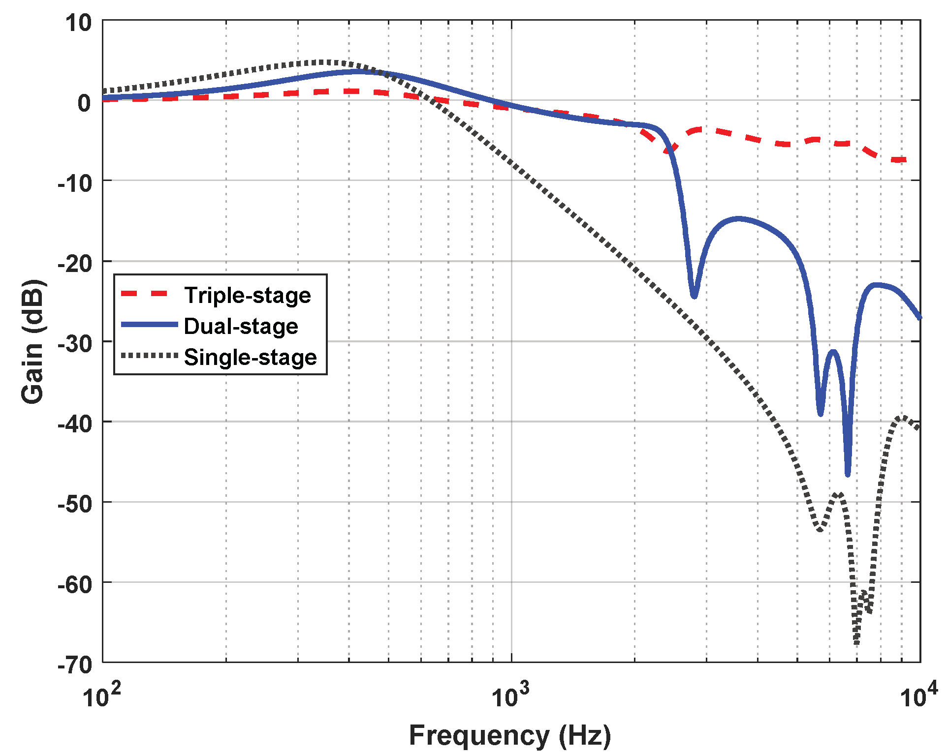
where is the open-loop transfer function of the system. Figure 14 and Figure 15 show the sensitivity and complementary sensitivity functions of single-stage, dual-stage, and triple-stage HDD servo systems. In Figure 14, it is seen that the triple-stage scheme has the lowest sensitivity for the low-frequency range although it has a bit higher complementary sensitivity for the high-frequency range. Therefore, the triple-stage scheme has better efficiency in terms of disturbance and noise reduction. So, in terms of a sensitivity analysis, triple-stage can be used as good control architecture.
7.2. Error Signal and Bandwidth
Figure 16 shows the error signal of each case and it is observed that the triple-stage architecture shows the minimum output error. Therefore, triple-stage architecture has better efficiency than the other two architectures.
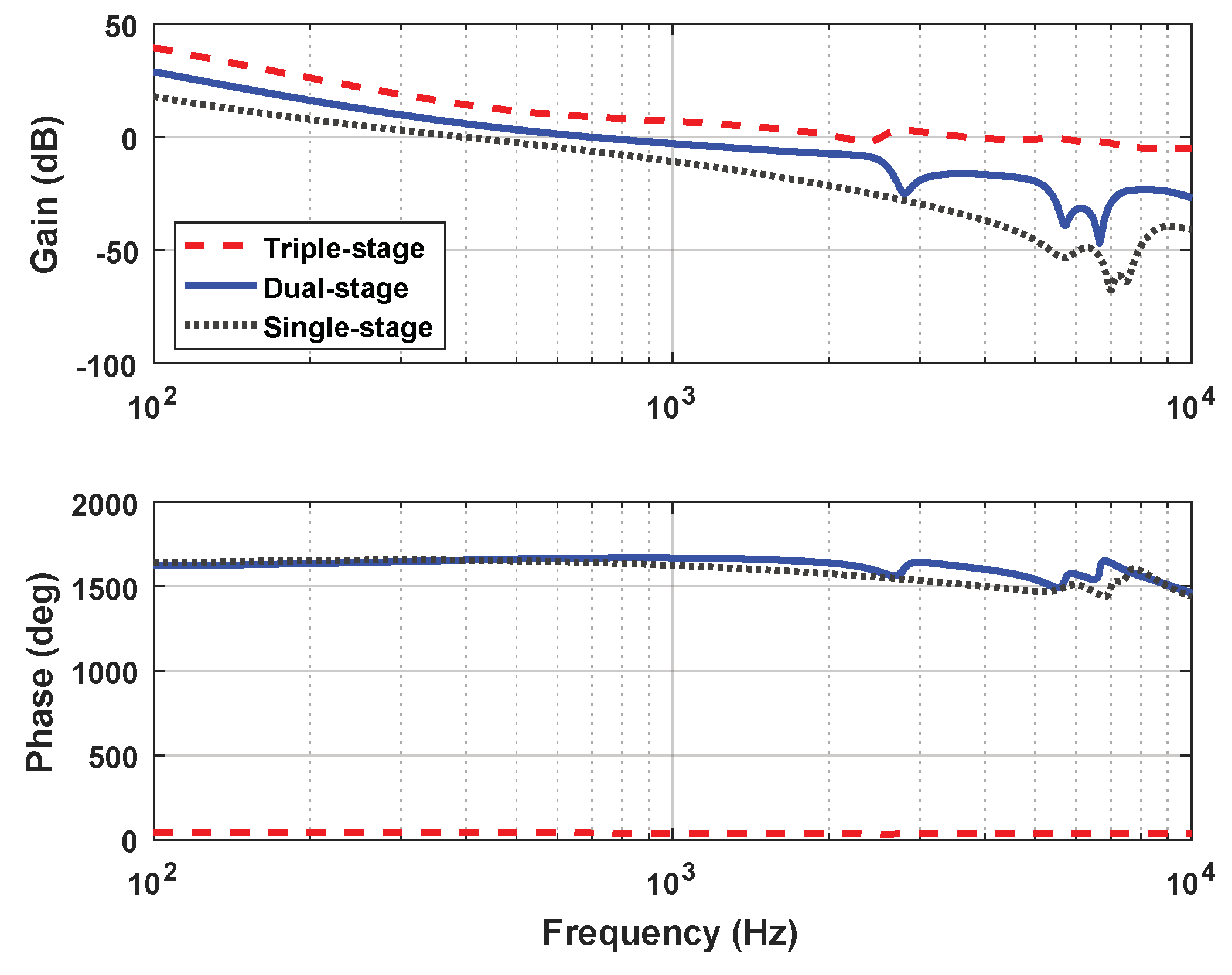
Bandwidth is the key parameter to determine the speed of an HDD servo system. Since speed is related to the bandwidth, a higher bandwidth provides a higher speed. Figure 17 displays the open-loop frequency response of the single-stage, dual-stage, and triple-stage architecture of an HDD servo system. It is seen that from the frequency responses, the TPC actuator gives the maximum cross-over frequency. As a result, the bandwidth of triple-stage architecture is bigger than dual-stage or single-stage architecture. The results of all combinations have been summarized in Table 4.
It is observed in Table 4 that triple-stage gives the minimum rise time (71.69–89.69 µs), minimum settling time (1281–1312 µs), minimum percentage overshoot (4.7–7.0%), higher bandwidth (3.671–4.356 kHz), higher phase margin (75.2°–79.9°) and infinite gain margin.
8. Conclusions
This paper presents the comparative analysis of different controllers for single-stage, dual-stage, and triple-stage high-precision position control systems. The frequency response of VCM and PZT actuators consist of multiple resonant modes. To overcome the effect of these resonant modes, notch filters were designed. In the case of dual-stage DMS architecture, PI-PD, PD-PD, and PID-PD combination, the result is a suitable performance. In another simulation, a lag-lead controller was used as the primary controller and a lag filter was used as the secondary controller. This combination shows better performance when the open-loop cross over frequency of a lag-lead controller changes from 400 Hz to 500 Hz and the cross-over frequency of the lag filter changes from 1600 Hz to 2000 Hz. In the triple-stage architecture, the system is simulated by considering the optimized result obtained in the dual-stage architecture. It is observed from the obtained data that when the PID controller is used as the tertiary stage, it performs better. In another combination of triple-stage architecture, lag-lead controller was used as the primary controller, lag filter was used as the secondary controller, and an inverse lead with PI controller was used as the tertiary controller. The system performs best when the open-loop cross-over frequency of the inverse lead controller changes from 3000 Hz to 4000 Hz.
The simulation results demonstrate that the triple-stage architecture provided superior performance when compared to dual-stage and single-stage architecture in terms of sensitivity, bandwidth, and tracking performance. Therefore, in order to increase the storage capacity of HDDs, a TPC actuator can be used as the tertiary actuator for the upcoming next-generation HDD.
Author Contributions
Formal analysis, A.H.; methodology, A.H.; software, A.H.; supervision, M.A.R.; writing—original draft, A.H.; writing—review and editing, M.A.R.
Funding
This research received no external funding.
Conflicts of Interest
The authors declare no conflict of interest.
References
- Hsia, Y.T. The ever shrinking hard disk drive and its components: What are the challenges? In Proceedings of the IEEE International Symposium on MicroNanoMechanical and Human Science, Nagoya, Japan, 5–8 November 2006; pp. 1–2. [Google Scholar]
- Li, Y.F. Dual-Stage Servo Control and Active Vibration Compensation in Magnetic Hard Disk Drives. Ph.D. Thesis, University of California, Berkeley, CA, USA, 2003. [Google Scholar]
- Huang, X.; Nagamune, R.; Horowitz, R.; Li, Y. Design and analysis of a dual-stage disk drive servo system using an instrumented suspension. In Proceedings of the IEEE American Control Conference, Boston, MA, USA, 30 June–2 July 2004; Volume 1, pp. 535–540. [Google Scholar]
- Guo, L.; Martin, D.; Brunnett, D. Dual-stage actuator servo control for high density disk drives. In Proceedings of the IEEE on Advanced Intelligent Mechatronics, Atlanta, GA, USA, 19–23 September 1999; pp. 132–137. [Google Scholar]
- Semba, T.; Hirano, T.; Hong, J.; Fan, L.S. Dual-stage servo controller for HDD using MEMS actuator. In Proceedings of the IEEE International Magnetics Conference, Kyongju, Korea, 18–21 May 1999; pp. 2271–2273. [Google Scholar]
- Al Mamun, A.; Guo, G.; Bi, C. Hard Disk Drive Mechatronics and Control; CRC Press: Boca Raton, FL, USA, 2006; Volume 23. [Google Scholar]
- Rahman, M.A.; Al Mamun, A.; Yao, K. Analysis and modeling of hysteresis of piezoelectric micro-actuator used in high precision dual-stage servo system. Control Theory Technol. 2015, 13, 184–203. [Google Scholar] [CrossRef]
- Pang, C.K.; Guo, G.; Chen, B.M.; Lee, T.H. Self-sensing actuation for nano-positioning and active-mode damping in dual-stage HDDs. IEEE/ASME Trans. Mechatron. 2006, 11, 328–338. [Google Scholar] [CrossRef]
- Guo, G.; Qi, H.; Low, T.S. A dual-stage control design for high track per inch hard disk drives. IEEE Trans. Magn. 2001, 37, 860–865. [Google Scholar]
- Lee, S.; Kim, Y.; Chung, C.C. Dual-stage actuator disk drives for improved servo performance: Track follow, track seek, and settle. IEEE Trans. Magn. 2001, 37, 1887–1890. [Google Scholar]
- Al-Mamun, A.; Mareels, I.; Lee, T.H.; Tay, A. Dual stage actuator control in hard disk drive-a review. In Proceedings of the 29th Annual Conference of the IEEE Industrial Electronics Society, Roanoke, VA, USA, 2–6 November 2003; pp. 2132–2137. [Google Scholar]
- Al-Mamun, A.; Suthasun, T.; Sri-Jayantha, S.M.; Lee, T.H. Multirate controller for dual actuated servomechanism in hard disk drive. Control Intell. Syst. 2007, 35, 32–43. [Google Scholar] [CrossRef]
- Nagel, W.S.; Clayton, G.M.; Leang, K.K. Master-slave control with hysteresis inversion for dual-stage nano-positioning systems. In Proceedings of the IEEE American Control Conference, Boston, MA, USA, 6–8 July 2016; pp. 655–660. [Google Scholar]
- Yu, S.; Li, Y.; Guo, L. Microactuator Servo Control During Self Writing of Servo Data. U.S. Patent 7,027,253, 11 April 2006. [Google Scholar]
- Rahman, M.A.; Al Mamun, A.; Yao, K.; Daud, Y. Discrete-time model predictive control for head-positioning servomechanism in a dual-stage hard disk drive. In Proceedings of the IEEE International Conference on Mechatronics and Automation, Tianjin, China, 3–6 August 2014; pp. 8–13. [Google Scholar]
- Wu, D.; Guo, I.G.; Chong, T.C. Analysis and comparison of resonance compensation in dual-stage actuation system of HDDs. In Proceedings of the IEEE American Control Conference, Arlington, VA, USA, 25–27 June 2001; pp. 3824–3829. [Google Scholar]
- Horsley, D.A.; Hernandez, D.; Horowitz, R.; Packard, A.K.; Pisano, A.P. Closed-loop control of a microfabricated actuator for dual-stage hard disk drive servo systems. In Proceedings of the IEEE American Control Conference, Philadelphia, PA, USA, 26 June 1998; pp. 3028–3032. [Google Scholar]
- Guo, W.; Weerasooriya, S.; Goh, G.B.; Li, Q.H.; Bi, C.; Chang, K.T.; Low, T.S. Dual stage actuators for high density rotating memory devices. IEEE Trans. Magn. 1998, 34, 450–455. [Google Scholar] [CrossRef]
- Hidehiko, N.; Tomizuka, M. Settling control and performance of a dual-actuator system for hard disk drives. IEEE/ASME Trans. Mechatron. 2003, 8, 431–438. [Google Scholar]
- Mike, S.; Miyake, K.; Kurita, M.; Tanaka, H.; Saegusa, S.; Robertson, N. Verification of thermally induced nanometer actuation of magnetic recording transducer to overcome mechanical and magnetic spacing challenges. IEEE Trans. Magn. 2005, 41, 4350–4352. [Google Scholar]
- Masayuki, K.; Xu, J.; Tokuyama, M.; Nakamoto, K.; Saegusa, S.; Maruyama, Y. Flying-height reduction of magnetic-head slider due to thermal protrusion. IEEE Trans. Magn. 2005, 41, 3007–3009. [Google Scholar]
- Song, S.; Wang, L.; Rudman, V.; Fang, D.; Stoev, K.; Wang, J.; Sun, B. Finite element analysis of alternating write-current-induced pole tip protrusion in magnetic recording heads. IEEE Trans. Magn. 2007, 43, 2217–2219. [Google Scholar] [CrossRef]
- Li, H.; Kurita, M.; Xu, J.; Yoshida, S. Iteration method for analysis of write-current-induced thermal protrusion. Microsyst. Technol. 2010, 16, 161. [Google Scholar] [CrossRef]
- Atsumi, T. Emerging technology for head-positioning system in HDDs. IEEJ J. Ind. Appl. 2016, 5, 117–122. [Google Scholar] [CrossRef]
- Atsumi, T. Flying-height and tracking-position controls with thermal-positioning actuator in hard disk drives. J. Adv. Mech. Des. Syst. Manuf. 2017, 11, JAMDSM0027. [Google Scholar] [CrossRef]
- Atsumi, T.; Suzuki, K.; Nakamura, S.; Ohta, M. Vibration control with thin-film-coil actuator for head-positioning system in hard disk drives. J. Adv. Mech. Des. Syst. Manuf. 2015, 9, JAMDSM0010. [Google Scholar] [CrossRef]
- Wit, D.; Canudas, C.; Olsson, H.; Astrom, K.J.; Lischinsky, P. A new model for control of systems with friction. IEEE Trans. Autom. Control 1995, 40, 419–425. [Google Scholar]
- Wit, D.; Canudas, C.; Olsson, H.; Astrom, K.J.; Lischinsky, P. Dynamic friction models and control design. In Proceedings of the IEEE American Control Conference, San Francisco, CA, USA, 2–4 June 1993; pp. 1920–1926. [Google Scholar]
- Mori, K.; Munemoto, T.; Otsuki, H.; Yamaguchi, Y.; Akagi, K. A dual-stage magnetic disk drive actuator using a piezoelectric device for a high track density. IEEE Trans. Magn. 1991, 27, 5298–5300. [Google Scholar] [CrossRef]
- Evans, R.B.; Griesbach, J.S.; Messner, W.C. Piezoelectric microactuator for dual stage control. IEEE Trans. Magn. 1999, 35, 977–982. [Google Scholar] [CrossRef]
- Yoshikazu, S.; Ichikawa, S.; Tsuna, T.; Sato, Y.; Sato, I. Piezoelectric piggy-back microactuator for hard disk drive. IEEE Trans. Magn. 1999, 35, 983–987. [Google Scholar]
- Hae-Joong, L.; Jeong, M.C. Apparatus and Method for Providing Axial Control Outside Impact Resistance of a Hard Disk Drive to Maintain a Constant Flying Height of a Head by Control of a Suspension. U.S. Patent 6,351,341, 26 February 2002. [Google Scholar]
- Chen, T.; Yamashita, T.T.; Lee, K.H.; Sakane, Y. Hard Disk Drive System Having Virtual Contact Recording. U.S. Patent 5,673,156, 30 September 1997. [Google Scholar]
- Lee, T.L. Thermal Compensated Head Positioner Servo for Disk Drive. U.S. Patent 5,128,813, 7 July 1992. [Google Scholar]
- Masaki, O.; Atsumi, T.; Otsuki, H.; Arisaka, T. Head-positioning control system using thermal actuator in hard disk drives. Microsyst. Technol. 2013, 19, 1483–1494. [Google Scholar]
- Gupta, B.K.; Young, K.; Chilamakuri, S.K.; Menon, A.K. On the thermal behavior of giant magnetoresistance heads. Trans. Am. Soc. Mech. Eng. J. Tribol. 2001, 123, 380–387. [Google Scholar] [CrossRef]
- Juang, J.Y.; Bogy, D.B. Air-bearing effects on actuated thermal pole-tip protrusion for hard disk drives. J. Tribol. 2007, 129, 570–578. [Google Scholar] [CrossRef]
- Masayuki, K.; Shiramatsu, T.; Miyake, K.; Kato, A.; Soga, M.; Tanaka, H.; Saegusa, S.; Suk, M. Active flying-height control slider using MEMS thermal actuator. Microsyst. Technol. 2006, 12, 369–375. [Google Scholar]
- Toshiya, S.; Kurita, M.; Miyake, K.; Suk, M.; Ohki, S.; Tanaka, H.; Saegusa, S. Drive integration of active flying-height control slider with micro thermal actuator. IEEE Trans. Magn. 2006, 42, 2513–2515. [Google Scholar]
- Hiroshi, F.; Hori, Y.; Kawamura, A. Perfect tracking control based on multirate feedforward control with generalized sampling periods. IEEE Trans. Ind. Electron. 2001, 48, 636–644. [Google Scholar]
- Chen, Y.Q.; Moore, K.L.; Yu, J.; Zhang, T. Iterative learning control and repetitive control in hard disk drive industry-a tutorial. In Proceedings of the IEEE Conference on Decision and Control, San Diego, CA, USA, 13–15 December 2006; pp. 2338–2351. [Google Scholar]
- Doh, T.Y.; Ryoo, J.R.; Chung, M.J. Design of a repetitive controller: An application to the track-following servo system of optical disk drives. IEE Proc. Control Theory Appl. 2006, 153, 323–330. [Google Scholar] [CrossRef]
Figure 1.
Single-stage actuation system.

Figure 2.
Dual-stage actuation system.

Figure 3.
Triple-stage actuation system.

Figure 4.
The frequency response of the voice coil motor (VCM) model.

Figure 5.
The frequency response of a complicated lead-zirconate-titanate (PZT) model.
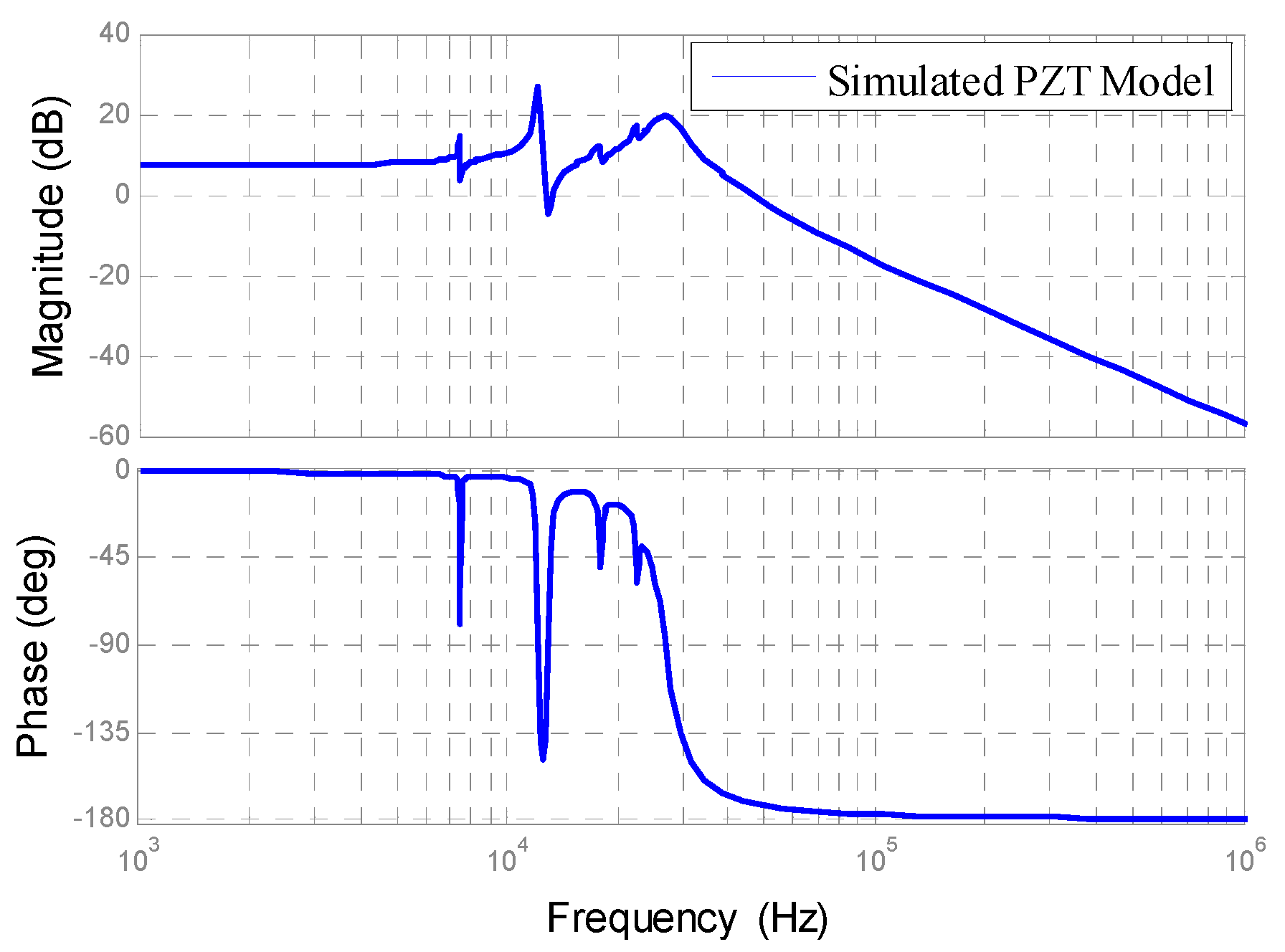
Figure 6.
The frequency response of the thermal positioning controller (TPC) model.

Figure 7.
Single-stage control architecture.

Figure 8.
Dual-stage control architecture.
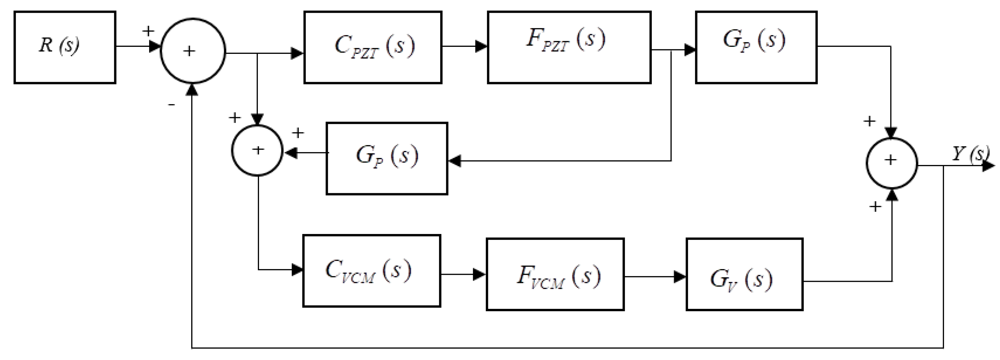
Figure 9.
Decoupled master–slave control architecture for triple-stage hard disk drive (HDD).

Figure 10.
The frequency response of the VCM model, and the VCM model with a notch filter.

Figure 11.
The frequency response of a notch filter for VCM.
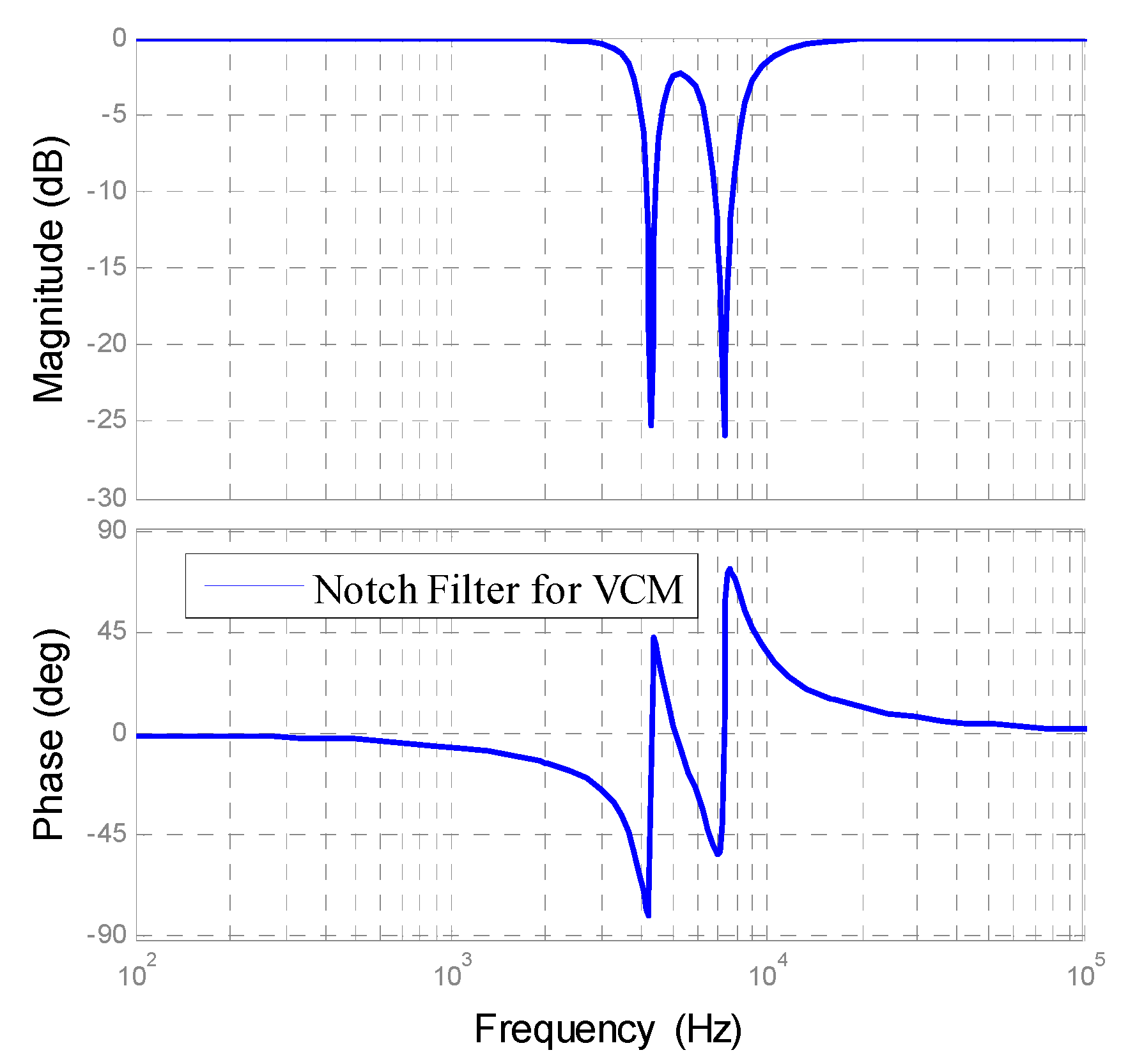
Figure 12.
The frequency response of the complicated PZT model and complicated the PZT model with a notch filter.
Figure 12.
The frequency response of the complicated PZT model and complicated the PZT model with a notch filter.
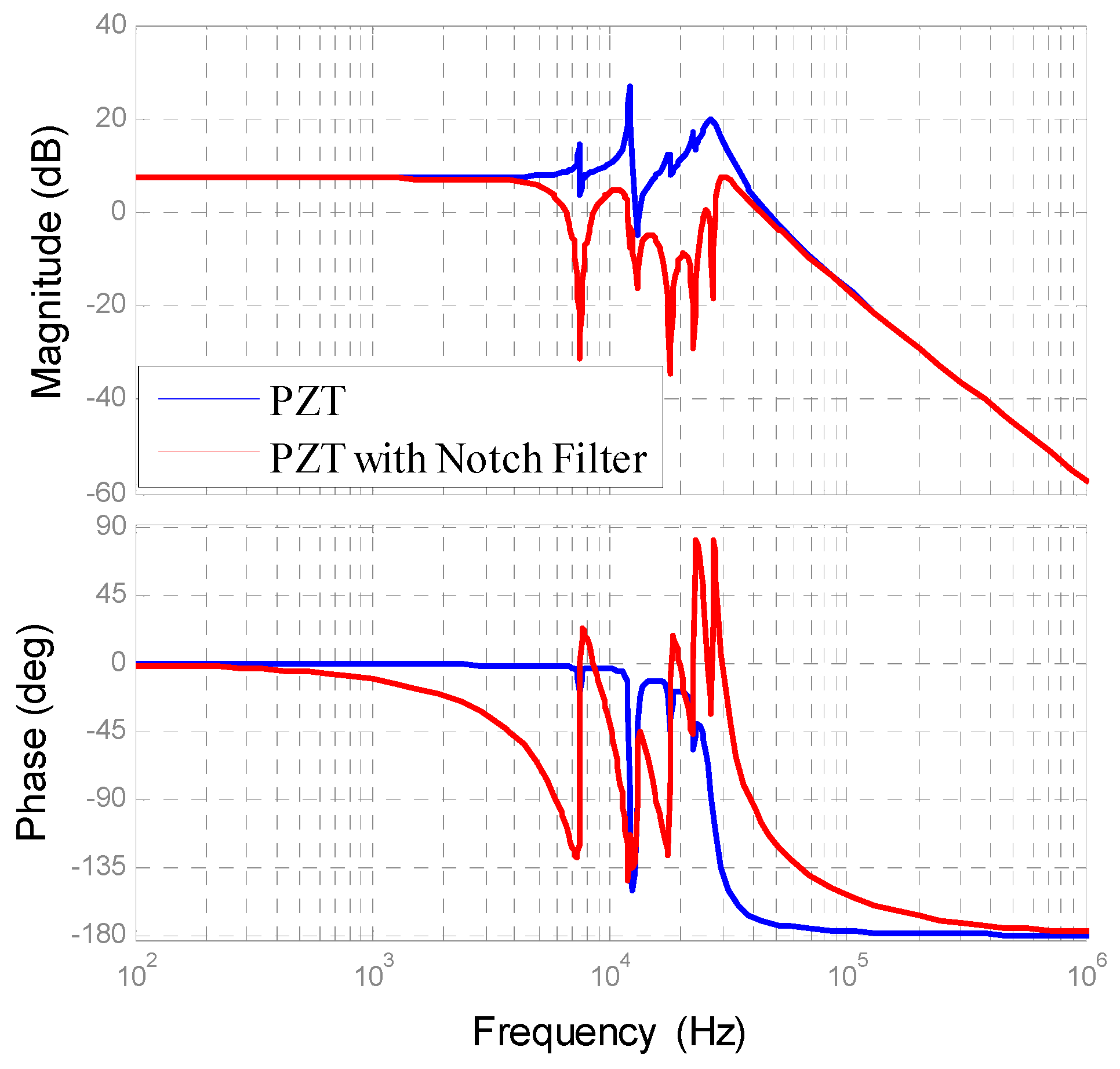
Figure 13.
The frequency response of a notch filter for a complicated PZT.

Figure 14.
Sensitivity plot of different control schemes.

Figure 15.
Complementary sensitivity plot of different control schemes.

Figure 16.
Error signal.
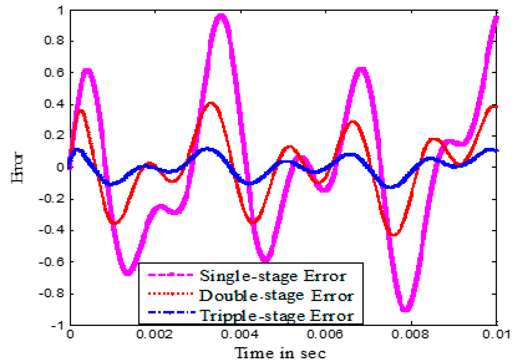
Figure 17.
The open-loop frequency response of single-stage, dual-stage, and triple-stage.

Table 1.
Summary of the proportional plus integral plus derivative (PID) controller.
| Controller | Rise Time (µs) | Settling Time (µs) | % Overshoot | Bandwidth (kHz) | Gain Margin (dB) | Phase Margin (Degree) |
|---|---|---|---|---|---|---|
| PI-PD-PID | 0.3592 | 1.732 | 18.4 | 699 | 202.9 | 60.4 |
| PD-PD-PID | ||||||
| PID-PD-PID |
Table 2.
Summary of the lag-lead controller as the primary controller and the lag filter as the secondary controller.
Table 2.
Summary of the lag-lead controller as the primary controller and the lag filter as the secondary controller.
| Open-Loop Cross-Over Freq. (fv) | Open-Loop Cross-Over Freq. (fm) | Rise Time (µs) | Settling Time (µs) | % Overshoot | Open-Loop Freq. (Hz) | Gain Margin (dB) | Phase Margin (Degree) |
|---|---|---|---|---|---|---|---|
| 1600 | 160.3 | 1700 | 12.3 | 1572 | 32.89 | 435.0 | |
| 400 | 1800 | 146.4 | 1727 | 11.1 | 1653 | 31.85 | 436.6 |
| 2000 | 137.0 | 1754 | 10.2 | 1915 | 30.92 | 435.7 | |
| 500 | 1600 | 146.8 | 1305 | 15.7 | 1572 | 32.89 | 429.1 |
| 1800 | 137.7 | 1325 | 14.1 | 1703 | 31.85 | 430.8 | |
| 2000 | 130.5 | 1344 | 12.9 | 1915 | 30.92 | 431.1 |
Table 3.
Summary for an inverse lead plus proportional plus integral (PI) controller as tertiary controller.
Table 3.
Summary for an inverse lead plus proportional plus integral (PI) controller as tertiary controller.
| fv (VCM) | fv (PZT) | fv (TPC) | Rise Time (µS) | Settling Time (µS) | % Overshoot | Open-Loop Bandwidth f0 (kHz) | Phase Margin (Degree) | Gain Margin (dB) |
|---|---|---|---|---|---|---|---|---|
| 400 | 1600 | 3000 | 89.69 | 1312 | 4.7 | 3671 | 79.90 | ∞ |
| 4000 | 81.22 | 1275 | 4.4 | 4136 | 82.77 | ∞ | ||
| 1800 | 3000 | 83.22 | 1332 | 6.0 | 3852 | 76.40 | ∞ | |
| 4000 | 75.88 | 1272 | 5.8 | 4290 | 78.90 | ∞ | ||
| 2000 | 3000 | 78.14 | 1341 | 7.2 | 4015 | 73.20 | ∞ | |
| 4000 | 71.69 | 1281 | 7.0 | 4356 | 75.20 | ∞ | ||
| 500 | 1600 | 3000 | 86.72 | 1026 | 6.8 | 3671 | 79.40 | ∞ |
| 4000 | 79.00 | 1001 | 6.5 | 4015 | 82.61 | ∞ | ||
| 1800 | 3000 | 81.09 | 1028 | 8.2 | 3852 | 76.00 | ∞ | |
| 4000 | 74.32 | 990.7 | 7.8 | 4225 | 79.30 | ∞ | ||
| 2000 | 3000 | 76.69 | 1024 | 9.4 | 4015 | 73.20 | ∞ | |
| 4000 | 70.61 | 988 | 8.9 | 4356 | 75.40 | ∞ |
Table 4.
Summary of results.
| Controller Stage | Rise Time (µs) | Settling Time (µs) | Percentage Overshoot (%) | Bandwidth (kHz) | Phase Margin (Degree) | Gain Margin (dB) |
|---|---|---|---|---|---|---|
| Dual (using PID) | 0.3588 | 1.729 | 18.4 | 697 | 60.4 | 202.9 |
| Dual II (using others) | 130–160 | 1344–1700 | 12.3–12.9 | 1.572–1.915 | 431.1–435 | 30.92–32.89 |
| Triple I (using PID) | 0.3592 | 1.732 | 18.4 | 699 | 60.4 | 202.9 |
| Triple II (using others) | 71.69–89.69 | 1281–1312 | 4.7–7.0 | 3.671–4.356 | 75.2–79.9 | ∞ |
© 2019 by the authors. Licensee MDPI, Basel, Switzerland. This article is an open access article distributed under the terms and conditions of the Creative Commons Attribution (CC BY) license (http://creativecommons.org/licenses/by/4.0/).
Share and Cite
MDPI and ACS Style
Hossain, A.; Rahman, M.A. Comparative Analysis among Single-Stage, Dual-Stage, and Triple-Stage Actuator Systems Applied to a Hard Disk Drive Servo System. Actuators 2019, 8, 65. https://doi.org/10.3390/act8030065
AMA Style
Hossain A, Rahman MA. Comparative Analysis among Single-Stage, Dual-Stage, and Triple-Stage Actuator Systems Applied to a Hard Disk Drive Servo System. Actuators. 2019; 8(3):65. https://doi.org/10.3390/act8030065
Chicago/Turabian StyleHossain, Alamgir, and Md. Arifur Rahman. 2019. "Comparative Analysis among Single-Stage, Dual-Stage, and Triple-Stage Actuator Systems Applied to a Hard Disk Drive Servo System" Actuators 8, no. 3: 65. https://doi.org/10.3390/act8030065
Note that from the first issue of 2016, this journal uses article numbers instead of page numbers. See further details here.