1. Introduction
The advancements in computational procedures and parallel processing of the last few years enhanced the accurate dynamic analysis and seismic assessments of multi-storey buildings. The analyses can be carried out at the building or urban level and high-fidelity models or sophisticated large-scale simulations can be adopted, respectively. In particular, a dynamic analysis of the entire urban area needs optimized computation procedures and simplified although accurate numerical models. Thus, a new and renovated interest has grown in beam-like models, which were introduced in the last century. Beam-like models, which are based on the equivalence of multi-level structures to flexural-shear coupling continuum beams, aim to simulate the dynamic behaviour of multi-level buildings by drastically reducing the computational burden. Several authors demonstrated interest in beam-like models and proposed suitable simplified approaches for the dynamic analysis of multi-level structures.
With regard to high-rise buildings, the discretization of multi-floor frames with coupled beams was introduced in 1982 [
1]. The proposed approach was limited to the principal three modes and in the plane behaviour.
In 1993, other authors [
2] studied two-dimensional frames whose members where composed of reticular elements and proposed an approximate method, based on the definition of an equivalent continuous model to replace the repetitive cells, for determining displacements and stress characteristics. The equivalence between the lattice structure and the continuous model was established in terms of deformation energies; the continuous model was then analysed in a traditional finite element approach [
3,
4].
Later, an approximate method for estimating the maximum lateral displacement in multi-storey buildings, based on an equivalent continuous model, that linearly combines a flexural and a shear deformable cantilever beam, was introduced in 1996 [
5]. The lateral displacement of the buildings was given by the combination of shear and bending deformations and the maximum displacement was evaluated. The formulation was successively generalized [
6] to take into account the non-uniform lateral stiffness in multi-storey buildings which, when subjected to seismic excitation, assumes the shape of the fundamental mode of vibration. The uniform continuous model was subsequently used to find closed-form solutions capable of approximating the dynamic characteristics of the buildings (for example modal deformations, periods and modal participation factors) [
6]. An estimate of the ground acceleration request on the structures that respond linearly to the seismic motions was determined in [
7] for planar models.
Applying the concept of an "equivalent column", simple formulas were proposed in 2001 [
8] for evaluating the natural three-dimensional frequencies of the buildings. The method considered local bending of the single vertical elements, global bending of the frames/shear walls (associated with the axial deformation of the vertical elements) and shear deformations of the frames/shear walls. Approximate formulas were provided to take into account the interaction between translational and torsional modes for non-symmetrical buildings. The same author proposed approximated closed-form solutions for studying tall buildings subjected to horizontal loads for both symmetrical [
9] and non-symmetrical [
10] systems, in 2009 and 2014, respectively.
In 2003, other authors [
11] replaced the structures of the buildings with an equivalent sandwich beam that was defined by three types of stiffness deriving from the resistant elements: global bending stiffness, local bending rigidity and shear stiffness. The deformation energy of the equivalent beam was deduced from the generalization of Timoshenko’s theory [
12] for spatial problems, introducing separate contributions between global flexural stiffness and shear stiffness, on one hand, and between global flexural stiffness and local flexural stiffness on the other. In any case, the shape of the displacements had to be fixed in order to obtain the rigidity of the equivalent system, leaving the choice of a certain length (a sort of free length of element inflection) correspondent to the best equivalence. Using the obtained equivalent stiffness, an approximate expression was proposed for estimating the natural frequencies of symmetrical structures, while the lateral-torsional vibration modes were determined by an eigenvalue problem. Later, the proposed model was applied to estimate the basic internal forces [
13]. Unfortunately, the procedure for calculating the stiffness of the equivalent model was rather complicated and not entirely automatic.
In 2003, the Homogenization Method of Discrete Media (HMDM) to repetitive reticular structures composed of interconnected elements (beams or plates) was adopted in other researches, with the purpose of deducing the modal characteristics of the repetitive framed buildings [
14].
In 2010, a continuous model in which the distribution of stresses and the profile of displacements for a combined system of different structural elements, based on previous research [
15], was proposed [
16]. This model was applied to estimate the natural frequencies and modal forms of the tall buildings [
17,
18], obtaining acceptable errors if compared to Finite Element models.
Later, starting from 2014, an equivalent beam model, deformable in shear and torsion and capable of approximately reproducing the dynamic behaviour of the three-dimensional shear-type structures, was introduced [
19], and its aeroelastic instability to wind excitation has been analyzed [
20]. The model has been adopted also in other papers in 2019 [
21,
22], for studying the linear and nonlinear elastic behaviour of periodic tower buildings under the assumption that the beam is internally constrained, so that it is capable of experiencing shear strains and torsion only. The elasto-geometric and inertial characteristics of the beam are directly identified from a discrete model of a three-dimensional frame, via a homogenization process. A more refined Timoshenko beam-like model suitable for the dynamic analysis of periodic buildings has been recently proposed [
23].
As this excursus shows, the definition of an equivalent beam was not always simple and immediate, especially in case of three-dimensional, torsional coupling behaviour.
The reduction of complex structural systems to equivalent beam models is still an open challenge of great interest.
In this paper, a non-uniform beam-like model, which is able to take into account two different irregularities, is proposed. In particular, this model is suitable for the schematization of real buildings that do not have a uniform mass and stiffness distribution along the height and are characterized by unsymmetrical plans. The equation of motion of the proposed beam-like model is derived through the application of Hamilton’s principle. The linear dynamic behaviour of the non-uniform beam-like element is then evaluated by discretizing the continuous model according to a Rayleigh–Ritz approach based on an appropriate number of modal shapes of a uniform beam having only shear and torsional deformability [
24]. The proposed approach allows an accurate description of the dynamic behaviour of low- and mid-rise buildings with limited computational effort. Furthermore, eventual uncertainties in the parameters of the structure can be taken into account by means of an opportune calibration strategy, based on the introduction of appropriate correction stiffness coefficients.
Aiming at investigating the capabilities of the proposed approach to provide reliable dynamic responses of existing multi-storey reinforced concrete (RC) frame buildings designed to resist only gravity loading, three representative buildings are taken into account. In particular, the first is characterized only by a horizontal irregularity, the second one only by a vertical irregularity while horizontal and vertical irregularities are present in the last case study. Real accelerograms of earthquakes that recently struck the Italian peninsula have been selected for comparing the seismic responses of the beam-like models to those obtained by 3D FEM models. The comparison showed a good accuracy of the non-uniform beam-like model and encourages the authors to consider the proposed procedure as a very useful and powerful tool for the seismic assessment at the urban level. It is worth noting that several residential buildings not designed to withstand earthquakes are spread throughout Italy and their seismic assessment is still argued at political and academic levels. The use of reliable numerical models based on a reduced number of structural or dynamic information, such as the one here proposed, represents a powerful tool with economic and decision-making advantages. In this light,
Figure 1 conceptually shows how entire residential areas can be interpreted with beam-like models, facilitating their seismic assessment.
2. The Beam-Like Model
The proposed model consists of a 3D shear-torsional cantilever beam able to reproduce the dynamic behaviour of multi-storey buildings. In particular, when the building columns cross sections decrease along the height of the building, as is usual in structures that were designed to resist gravity loading only, the equivalent beam has a non-uniform virtual cross section. Furthermore, planar irregularities due to the unsymmetrical distribution of the columns or shear walls can be taken into account. This kind of irregularity must be properly considered since it induces eccentricity between the centers of stiffness and mass, thus causing unneglectable torsional effects. Each portion of the beam represents a building inter-storey, whose shear and torsional stiffness are initially approximately evaluated according to a geometric reference model. Once the beam-like model of the entire building is defined, it can be calibrated on a reduced number of modal properties that could be identified by means of ambient vibration techniques. It is worth noting that, although only elastic, the proposed beam-like model could also be used for defining an operativity limit state index based on inter-storey drift [
25,
26].
2.1. Kinematics of Frames and Beams
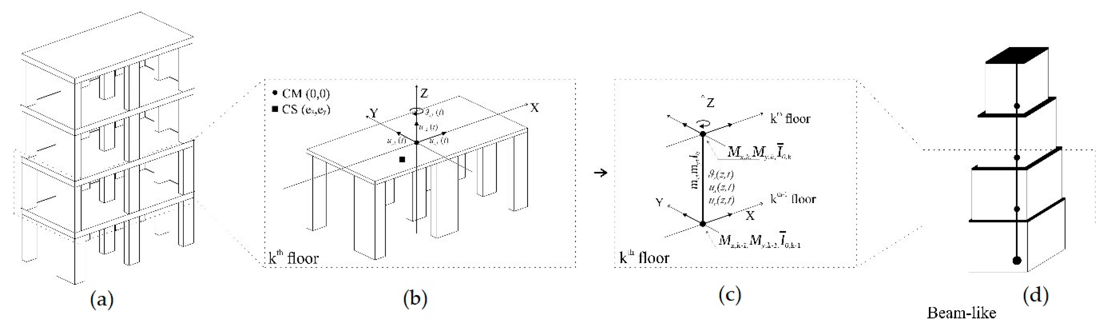
The proposed beam-like model (BLM) is able to represent 3D structures (
Figure 2a) by means of a 1D beam element (
Figure 2d). With reference to the
-th storey of the building in the
plane, shown in
Figure 2b, the centers of mass (CM) and stiffness (CS) will be assumed as not coincident to each other, thus inducing a torsional behaviour of the structure. It is worth noting that, at each floor, the CM point is placed on the global vertical axis (Z) and, consequently, the CS coordinates coincide with the CS–CM eccentricity
. Each inter-storey is modelled by a beam segment with uniform stiffness properties, distributed masses
and second order moment
. Concentrated values for the masses
and
, as well as the second order moment
, are applied at the end of each beam segment in order to simulate the presence of the beam and floor masses and applied loadings.
In order to simplify the description of the kinematics of the multi-storey frame, the hypothesis of rigid floors and inextensible columns have been assumed.
Figure 2b sketches the
-th storey and indicates the displacements
and the rotation
of the CM of the
-th rigid floor. According to the hypothesis of rigid floors, very often adopted in the literature, the end of each column, which has the coordinates
at each
-th floor level, has the following displacement components:
At this stage it could be anticipated that an original strategy to take into account also the out of plane floor deformability is proposed and discussed in the next sub-section.
Each building inter-storey
is modelled by means of an equivalent beam segment having the same length
and uniform properties (
Figure 2c).
Displacements in the and direction and rotations of the beam-like are assumed as continuous functions of the abscissa and denoted, respectively, as .
The complete non-uniform beam-like model is obtained by the sequence of all the beam segments with uniform properties each, as shown in (
Figure 2d).
2.2. The Inter-Storey Shear and Torsional Stiffness
The equivalent beam shear stiffness in the two principal directions, denoted as
, and the torsional stiffness, denoted as
, are obtained for the
-th inter-storey, by considering the contributes of all the
columns of the building whose base points have planar coordinates
. The adopted inter-storey stiffness values are:
In case of concrete columns, the flexural
and torsional
stiffness are:
where
is Young’s modulus;
the moment of inertia with respect to the
axis and
the rotational inertia moment of the
-th column of the
-th inter-storey.
In order to take into account the unknown or not properly identified structural properties (floor out-of-plane deformability, beam-column stiffness ratios and uncertainty on the position of the center of mass at each floor), three correction coefficients are introduced. These coefficients, denoted as
, correct the shear stiffness along the
and
directions and the torsional one that are listed in Equation (2). The actual stiffness values are therefore reported as follows:
As it will be shown in the following, the three correction coefficients can be evaluated by means of an iterative optimization procedure.
2.3. The Equations of Motion of the Proposed Non-Uniform Beam-Like Model
In order to evaluate the response of the non-uniform equivalent beam by introducing a limited number of degrees of freedom, a Rayleigh–Ritz discretization was performed. The discretization is based on the choice of an appropriate
number of modal shapes of a uniform shear cantilever beam, as displacement shape functions of the-non uniform beam, defined as follows:
where
is the dimensionless abscissa of the beam,
being the along-axis abscissa and
the beam length.
All the introduced displacements can therefore be expressed as
being the generalized
-th coordinates along the
directions, which represent the contribution of the single shape function to the total response.
The equations of motion of the proposed beam-like model are derived through the application of Hamilton’s principle. Displacements
,
at the base
are considered in the formulation in order to take into account seismic excitations. In the present formulation, primes and dots denote differentiation with respect to the normalized abscissa
and time
, respectively. In absence of non-conservative forces, Hamilton’s principle can be reduced to the contribution of kinematic
and elastic energy
only, as follows:
where
indicates the variation of the of the kinetic energy
and the elastic energy
, whose relevant expressions are provided in the
Appendix.
The equations of motion have been obtained imposing the appropriate variation of the generalized coordinates.
The mathematical notation of Hamilton’s principle provided by Equation (A3) can be simplified by omitting for convenience the dependency on
and
, and, furthermore, by rearranging all the terms in a more compact manner as follows:
The generalized mass matrix
, the stiffness matrix
, the load vector
and the vector
, appearing in Equation (8), are defined as follows:
where the relevant elements are given as:
where
is the shape function evaluated at the floor level,
is the number of floors and
represent the along axis variable shear and torsional stiffness that can be substituted with a step-wise distribution, constant for each inter-storey
, in accordance with the equivalent beam model adopted in
Figure 2d, as follows:
Finally, the equations of motion of the proposed equivalent multi-stepped beam in the generalized space are derived by Equation (8) in matrix notation as follows:
It is worth noting that the structural damping will be introduced, in terms of modal damping ratios, in the uncoupled equations of motions that will be derived in
Section 2.6.
2.4. Eigen-Problem of the Non-Uniform Beam-Like Model
As anticipated in
Section 2.2, the stiffness matrix terms given by Equation (10) are affected, in view of Equation (4), by the three correction coefficients
that are evaluated by taking into account the modal properties, such as frequencies and modal displacements. In this view, the modes of vibration in the generalized space, denoted as
, and the vibration frequencies
of the equivalent beam are obtained solving the following standard eigen-problem:
Consequently, the modal shape in the geometric space can be obtained by means of Equation (6), where the displacement shape functions of a uniform beam, of the type given in Equation (5), are considered.
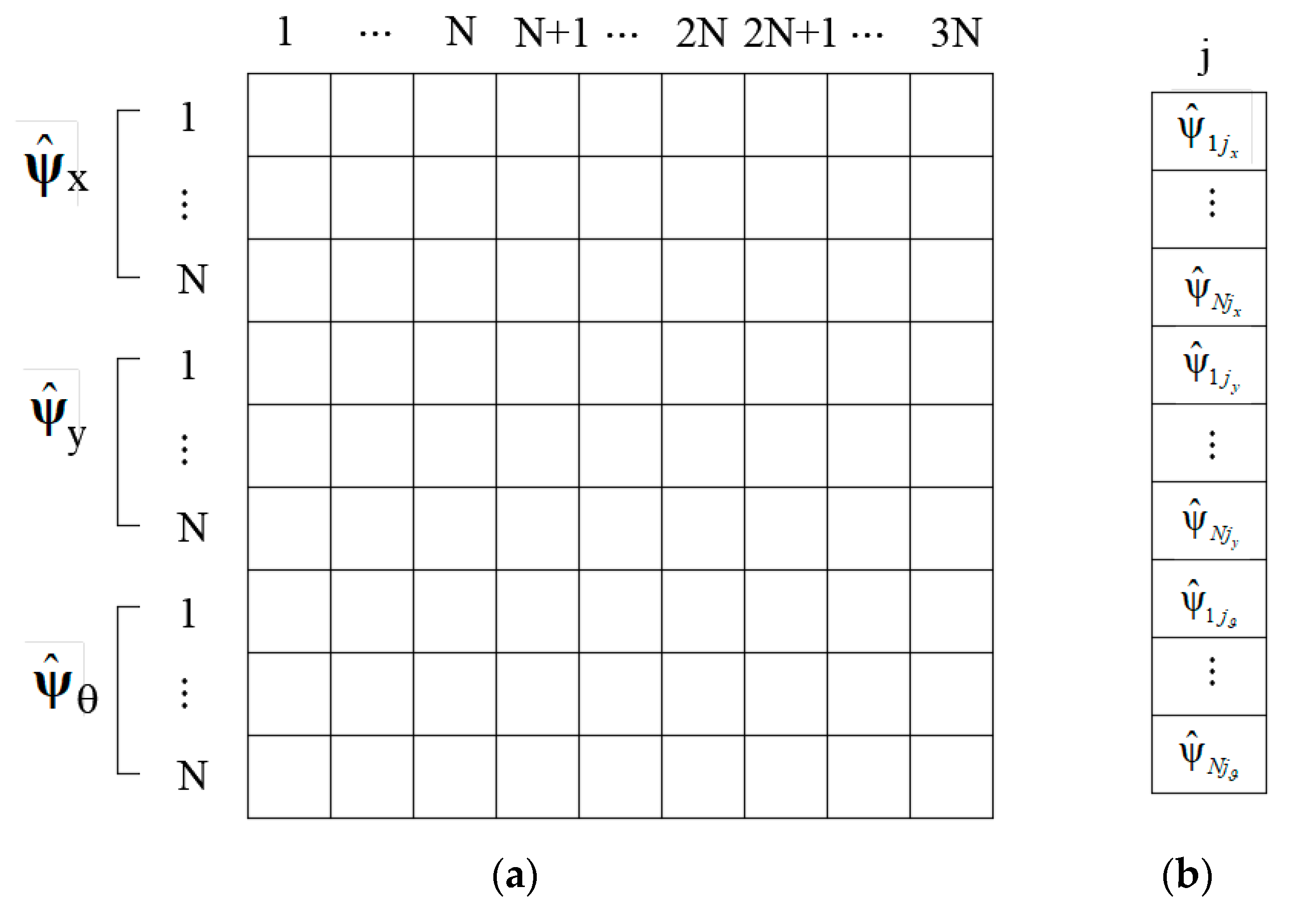
Therefore, since the solution of the multi-stepped beam is approximated with
shape functions, the mass and stiffness matrices have a
dimension and the solution of the eigen-problem, represented by Equation (15), is a
vector of natural frequencies and a
matrix of eigen-vectors.
Figure 3 depicts the eigen-vector matrix in the generalized space and the components of the generic
-th eigen-vector.
Consequently, the
-th modal shape in the geometric space of the equivalent non uniform multi-stepped beam, denoted as vector function
, is obtained, in view of Equation (6), by multiplying each displacement shape function of the uniform beam
, considered for the discretization, times the corresponding eigen-vector components.
Equation (16) provides the three spatial components in the actual geometric space (
Figure 2) of the
-th modal shape to be adopted to perform a suitable dynamic analysis of the equivalent non-uniform beam by means of a suitable modal superposition procedure, as shown later.
2.5. Shear and Torsional Beam Stiffness Optimization
The proposed non-uniform beam-like approach, in spite of its simplicity, can be enhanced to reproduce accurately the dynamic behaviour of 3D frame structures by coupling an iterative procedure aiming at optimizing the calibration of the shear and torsional stiffness of the equivalent beam, as described in what follows. Precisely, in order to consider all the unknown or improperly identified structural properties, three coefficients
are applied to correct the shear and the torsional stiffness as Equation (4) shows. It is worth noting that the eigen-properties of the non-uniform beam-like model are strictly dependent on the values of the correction coefficients
In order to identify the best values of
, appearing in Equation (4), the following objective function
is introduced:
where
and
is a Boolean parameter.
The objective function defined in Equation (17), dependent on the stiffness coefficients , represents a measure of the deviation with respect to target values of a given number of natural frequencies and modal displacement vector , evaluated at suitably chosen floor levels . The target values, denoted in Equation (17) with a superimposed tilde “~”, represent experimental values that could be obtained by means of dynamic identification methods. Bearing in mind that the present work aims at assessing the reliability of the proposed beam-like model and the suitability of the selected values for the stiffness coefficients , rather than testing a proper execution of dynamic identification methods, the target frequencies and modal shapes have been numerically obtained by means of detailed FEM models.
It is worth highlighting that the Boolean parameter
allows to include or neglect the modal shapes in the definition of the objective in Equation (17). As it will be shown in the applicative section, for buildings with only one irregularity (either planar or vertical) the knowledge of the first natural frequencies is sufficient for the determination of reliable stiffness-correction coefficients. On the other hand, when the considered structure has more than one irregularity (for example the building described in
Section 3.3), in order to evaluate the accurate stiffness correction coefficients, in addition to the frequencies, the modes of vibration must also be considered by setting
in the objective function.
The optimal values of the stiffness coefficients
, to be adopted for the non-uniform beam-like model equivalent to the given 3D frame structure, are those that minimize the objective function defined in Equation (17). The latter optimization problem is solved with an iterative solution procedure by means of the Bounded Minimization Pattern search algorithm [
27]. At each step of this algorithm, the trial value of the objective function was calculated by solving the eigen-problem in Equation (15) of the non-uniform equivalent beam, discretized as shown in
Section 2.3, by assuming trial values of the stiffness coefficients
. The values for these three variables, according to the algorithm options [
27], have been bounded in the range (0.1, 1). The choice of the upper bound of the range rises from the consideration that, since the considered beam exhibits only shear deformation, it is reasonably stiffer than the FEM model. The presence of out-of-plane floor deformability and flexural stiffness of the real structure leads to the identification of stiffness correction coefficients lower than one for the beam-like model. On the other hand, the lower bound has been chosen assuming that, since the initial shear and torsional stiffness of the beam-like have been defined according to the geometry of the building, a variation higher than 90% is not realistic.
2.6. Dynamic Response
The dynamic response of the BLM subjected to external loading, in the generalized space, can be expressed as a combination of
modes of vibration multiplied by the time-dependent functions
:
where
indicates the number of modes of vibration. Substitution of Equation (18) into the equation of motion (Equation (14)) leads to
Furthermore, in view of the orthogonality conditions of the vibration modes, Equation (19) provides
So, the equations of motions are simplified as follows:
It is worth noting that the terms are representative of the generalized modal damping for all the modes of vibration and are related to the corresponding modal damping ratios as follows: .
Lastly, the dynamic response in the geometric space is obtained by means of the following expressions:
where
is the number of modes of vibration and
is the number of shape functions.
3. Applications
In order to apply the proposed procedure to real structures with different irregularities, namely planar and vertical ones, in the present paper three multi-storey RC frames representative of residential buildings designed to resist only gravity loading have been considered. The considered buildings have been chosen taking into account the results of an extensive survey of existing multi-storey RC buildings built in Catania, Italy, before the introduction of the seismic code [
28,
29,
30]. The geometrical details of the typical building can be found in [
30], where further information on the loading and the material properties are reported.
A synthetic description of the proposed method, for a demonstrative purpose only, together with applications to simple spatial frames have been presented by the authors in previous works [
31,
32].
The three models of realistic buildings here considered will be denoted as Model Type 1, Type 2 and Type 3 in the following.
Type 1 refers to a building with planar asymmetry and vertical uniform distribution of mass and stiffness. Due to the peripheral staircase, which is located on one side of the building, the center of stiffness does not coincide with the center of mass. The eccentricity determinates torsional effects that are correctly identified by the proposed beam-like model. Due to the presence of planar asymmetry only (no vertical irregularity is introduced), the objective function introduced into Equation (17) to determine the stiffness correction coefficients of the equivalent beam model for Type 1 building, accounting for the natural frequencies only (i.e., = 0), provided accurate results.
Type 2 presents a planar symmetry and vertical non-uniform distribution of mass and stiffness due to the reduction of the cross sections of the columns along the height. Once again, due to the existence of only one of the considered irregularities (i.e., the vertical one), the minimization of the objective function in Equation (17) has been performed by considering only the frequencies of the vibration.
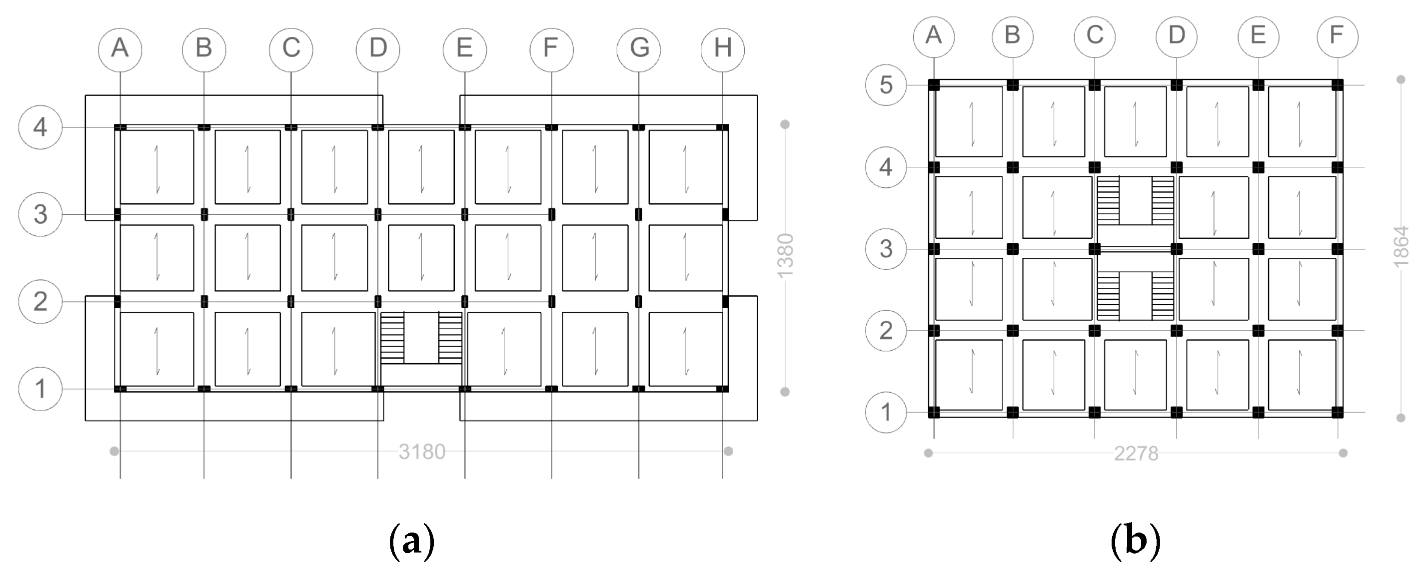
The structural plans of Type 1 and Type 2 are reported in
Figure 4 and the inter-storey height of both models is set equal to 3.30 m at each level.
In order to consider the contemporary occurrence of both the planar and vertical irregularities, Type 3 has been considered. The latter has been obtained by adding vertical asymmetries to the already-described Type 1. In this view, the height of the first floor has been incremented up to 4.3 m, and a reduction along the height of the building in the column cross-section has been introduced and a total number of six floors have been considered. In this case, due to the contemporary presence of the two types of irregularities, it will be shown that, in order to obtain a reliable dynamic response of the beam-like model, the contribution of the modal shape vector term in the objective function must also be considered; hence, = 1. Precisely, it is worth noting that only the modal displacements of the top floor have been introduced in the objective function (Equation (17)).
In all the three building types the dimensions of the cross sections of the beams on the edge were assumed to be 30 × 50 cm2, while all the remaining beams have a 110 × 23 cm2 size. The columns were assumed fully fixed at the base. An equivalent floor thickness of 9.32 cm at each level was considered. The material properties were characterized by a Young’s modulus of 29,962 MPa, a Poisson ratio equal to 0.2 and a mass density of 25 kN/m3.
The results, in terms of seismic response, were compared to those obtained by means of a conventional FEM model developed with SAP2000 [
33]. The reliability of the beam-like model was evaluated by comparing the time histories of the
and
displacements of some control points. For the sake of brevity, in the following only the results related to a control point located at the upper left corner of the highest floor are reported. Furthermore, the maximum displacements of the same corner located at each floor were calculated. In order to make an appropriate comparison between the two models, the in-plane rigid floor, no live loads and inextensible concrete columns were considered in the FEM model.
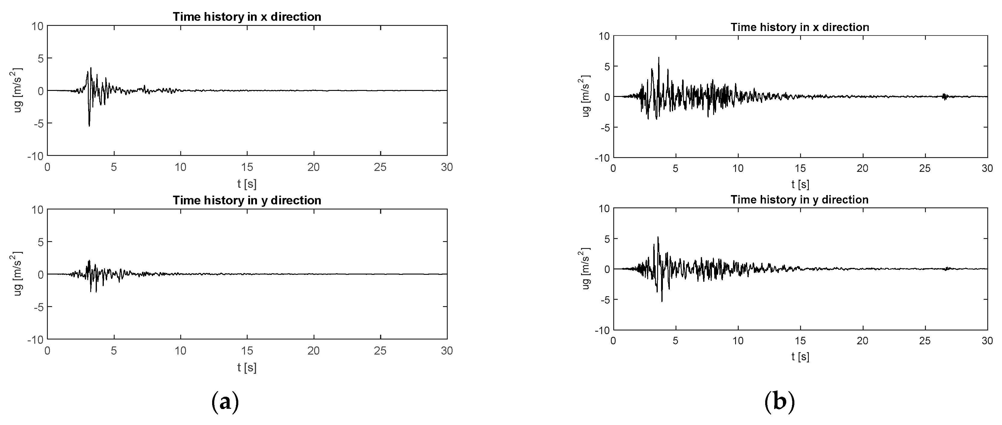
Aiming to simulate representative seismic inputs that may occur on the Italian peninsula, linear dynamic analyses were performed by considering two real seismic records [
34] in the
and
directions that occurred in Santa Venerina (2018) and L’Aquila (2009), plotted, respectively, in
Figure 5a,b. Some characteristic data of the two records (PGA, PGV, PGD, distance for epicenter) are reported in
Table 1. In all the time-histories, constant modal damping ratios
= 0.05, for all considered modes, were assumed.
3.1. Type 1: Building with Planar Asymmetry and Vertical Uniform Distribution of Mass and Stiffness
The four-storey model is characterized by uniform column cross-sections along the whole height. The planar distribution of the cross section of the columns is reported in
Figure 6a while
Figure 6b shows a scheme of the FEM model.
For this building, the minimization of the objective function provided the following values for the stiffness correction coefficients: .
Table 2 and
Figure 7 compare three periods and modal shapes, respectively, calculated through the FEM approach to those obtained by means of the proposed beam like model.
Aiming to numerically compare, for each considered building, the modal shapes that have been obtained by means of the beam-like and the FEM models, a consistency indicator is needed. The Modal Assurance Criterion (MAC) is here used calculating the following matrix elements:
where each term of the MAC matrix is bounded between 0 and 1.
Taking into account the orthogonality properties of the modes of vibration, a perfect coincidence between the modal shapes in the two models would provide a diagonal unitary matrix. Therefore, values close to 1 in the main diagonal of the matrix indicate a good correspondence of the modal shapes, while low values indicate that the modes are not consistent [
35].
For the Type 1 building analyzed in this section, the matrix MAC_Tp1 assume the following expression:
As it can be observed in
Figure 7, and confirmed by the MAC_Tp1 matrix, there is satisfactory agreement between the results obtained for the beam-like model, for all the modal properties related to the first two translational modes and to the third torsional one.
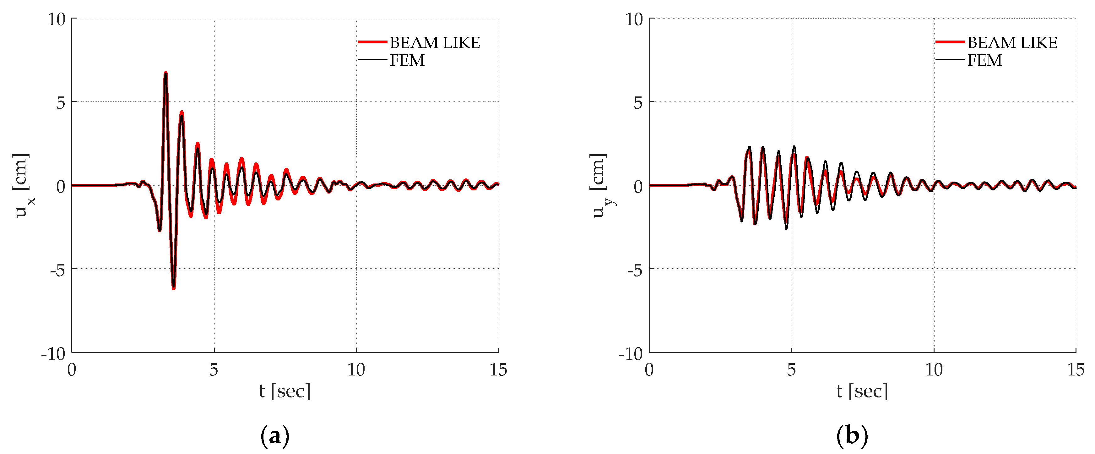
Figure 8 reports the displacement time histories of the control point in both the
and
directions, calculated by means of the beam-like and FEM models during the considered seismic excitation. In particular
Figure 8a,b report, respectively, the
and
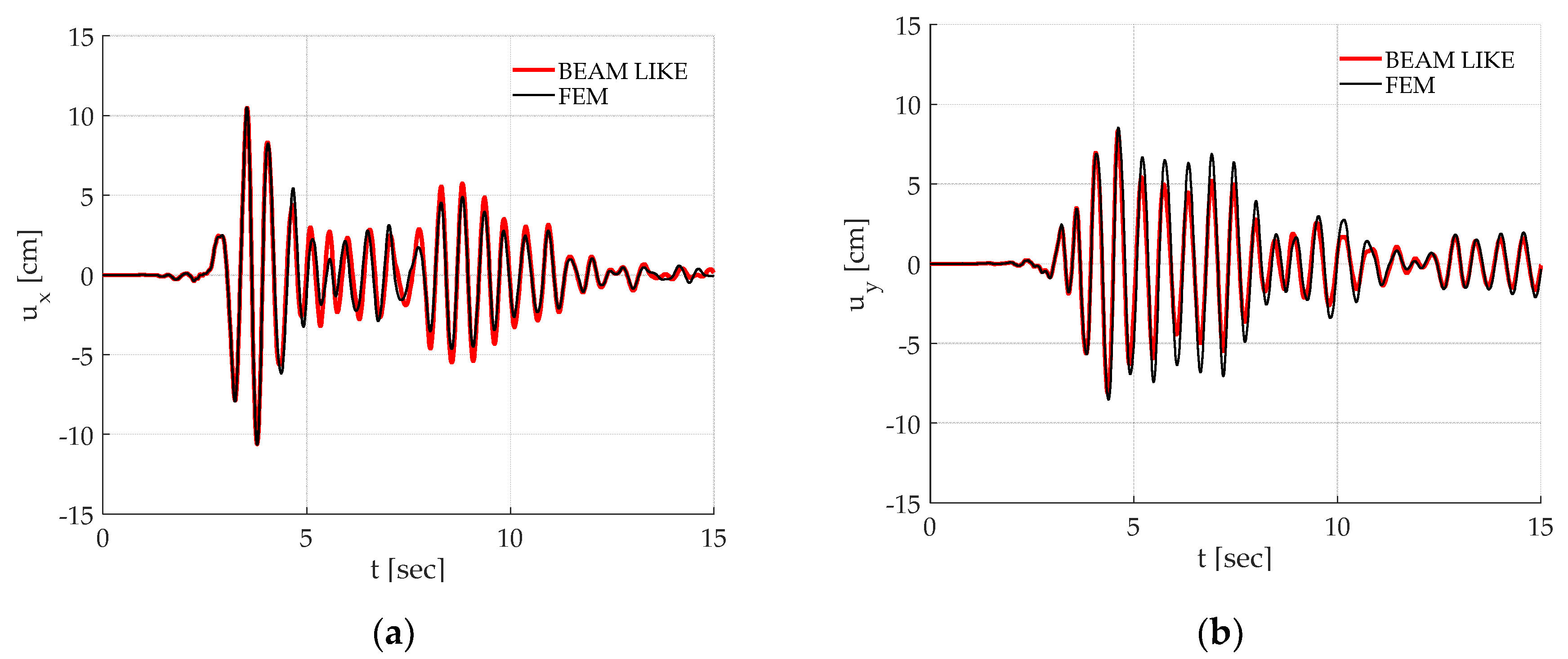
displacements due to the Santa Venerina earthquake loading. The correspondent results for the L’Aquila earthquake are reported in
Figure 9.
Once again, it must be remarked how the proposed approach is able to correctly reproduce the time history of a chosen point on the building. Finally, as it can be observed in
Figure 10, also the maxima displacements of the same corner located at each floor, calculated by means of the beam-like model, give reliable results.
3.2. Type 2: Building with Planar Symmetry and Vertical Non-Uniform Distribution of Mass and Stiffness
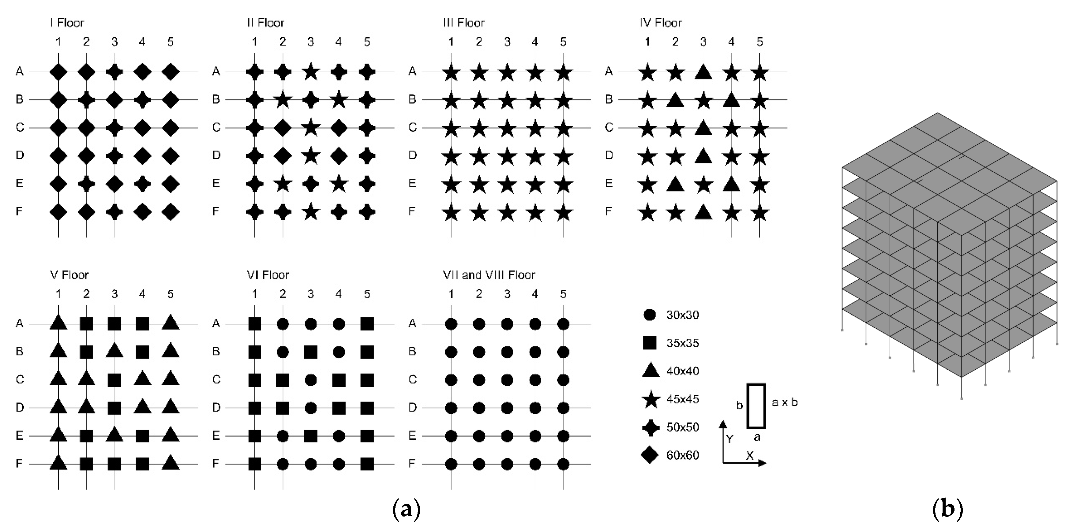
The second benchmark regards Type 2, an eight-storey frame characterized by a reduction of the cross sections of the columns along the height. The planar distribution of the cross section of the columns is reported for each floor in
Figure 11a, while
Figure 11b shows a scheme of the FEM model.
For this building the minimization of the objective function provided the following values for the stiffness correction coefficients: .
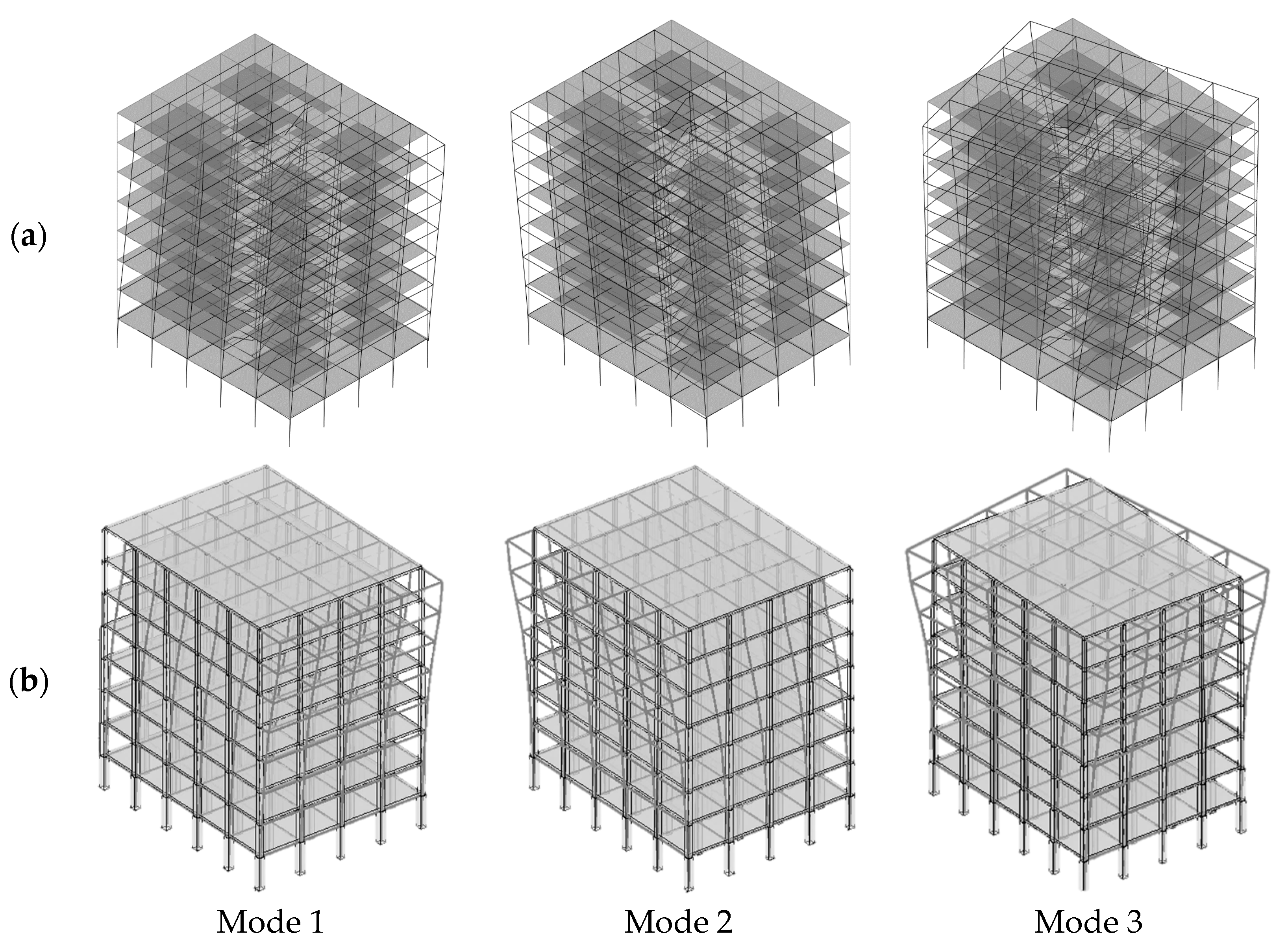
The first three modal properties of Type 2 evaluated by means of the proposed approach were compared to those obtained by the conventional FEM model and are reported in
Table 3 and
Figure 12.
For this building the matrix MAC_Tp2 assume the following expression:
The observation of
Figure 12 shows that the first and second mode of vibration are translational in the two directions while the third one is torsional. A good correspondence can be observed between the results obtained by means of the two approaches, as the MAC_Tp2 matrix confirms.
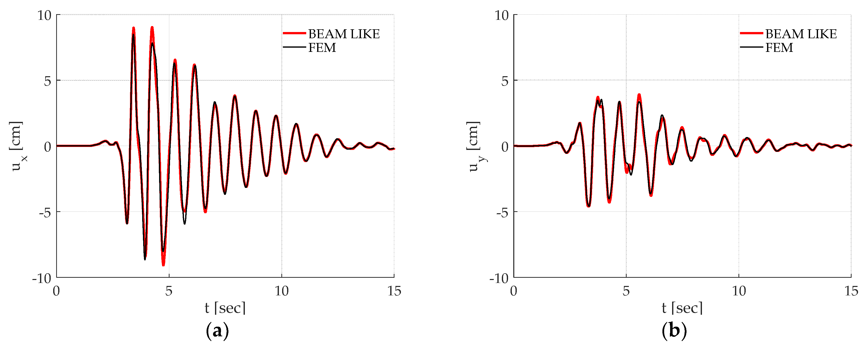
Figure 13 and
Figure 14 report the displacement time histories in the
and
directions of the considered control point during the Santa Venerina and L’Aquila earthquake, respectively. Minor differences can be noticed between the responses obtained by means of the two considered models, but they do not sensibly affect the global response.
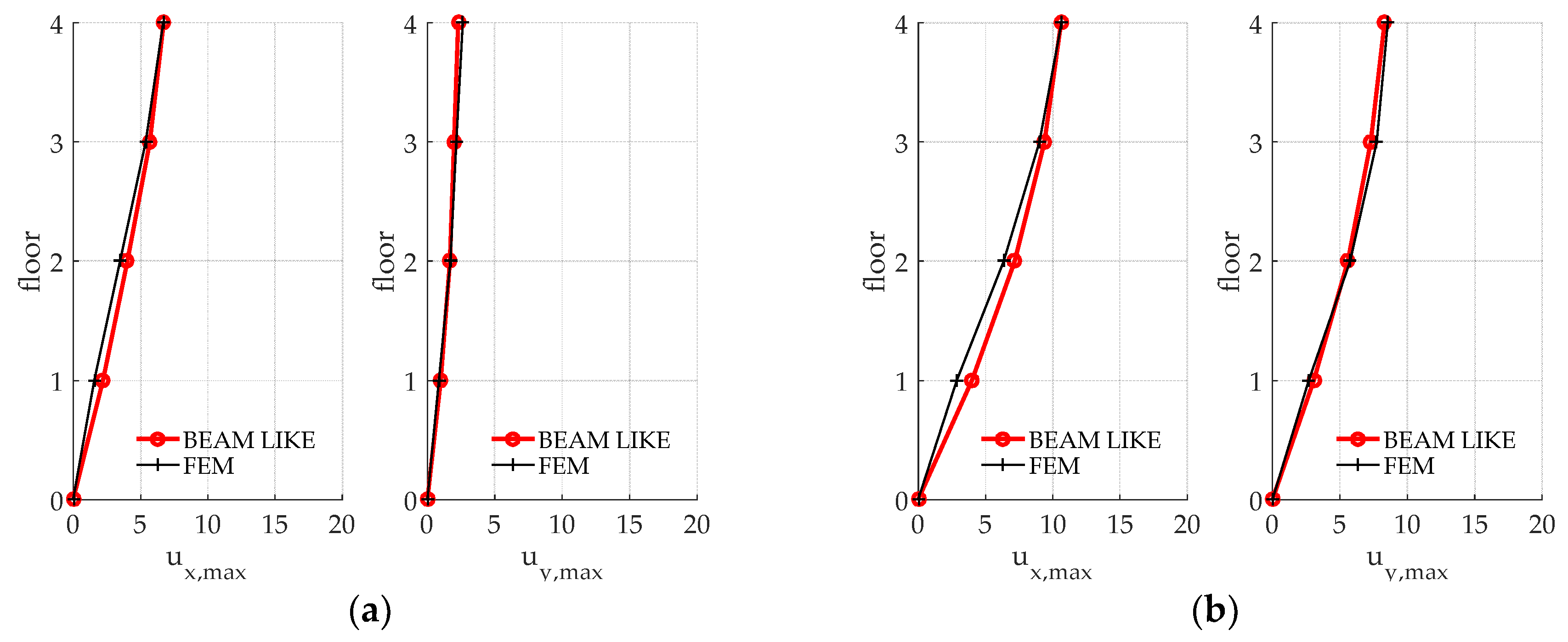
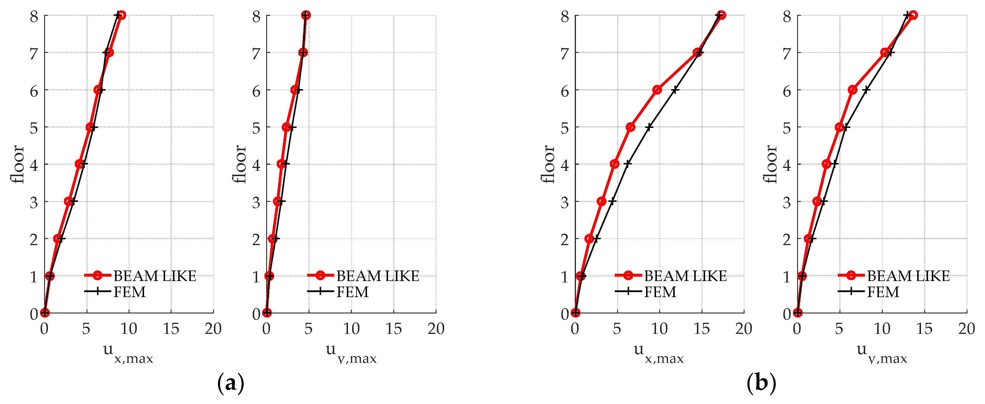
Figure 15 reports the maxima displacements of the same corner located at each floor level. Some small differences can be noticed in this case with reference to the intermediate floors but, globally, the proposed beam-like model reproduces the dynamic behaviour of this benchmark with satisfactory agreement.
3.3. Type 3: Building with Planar Asymmetry and Vertical Non-Uniform Distribution of Mass and Stiffness
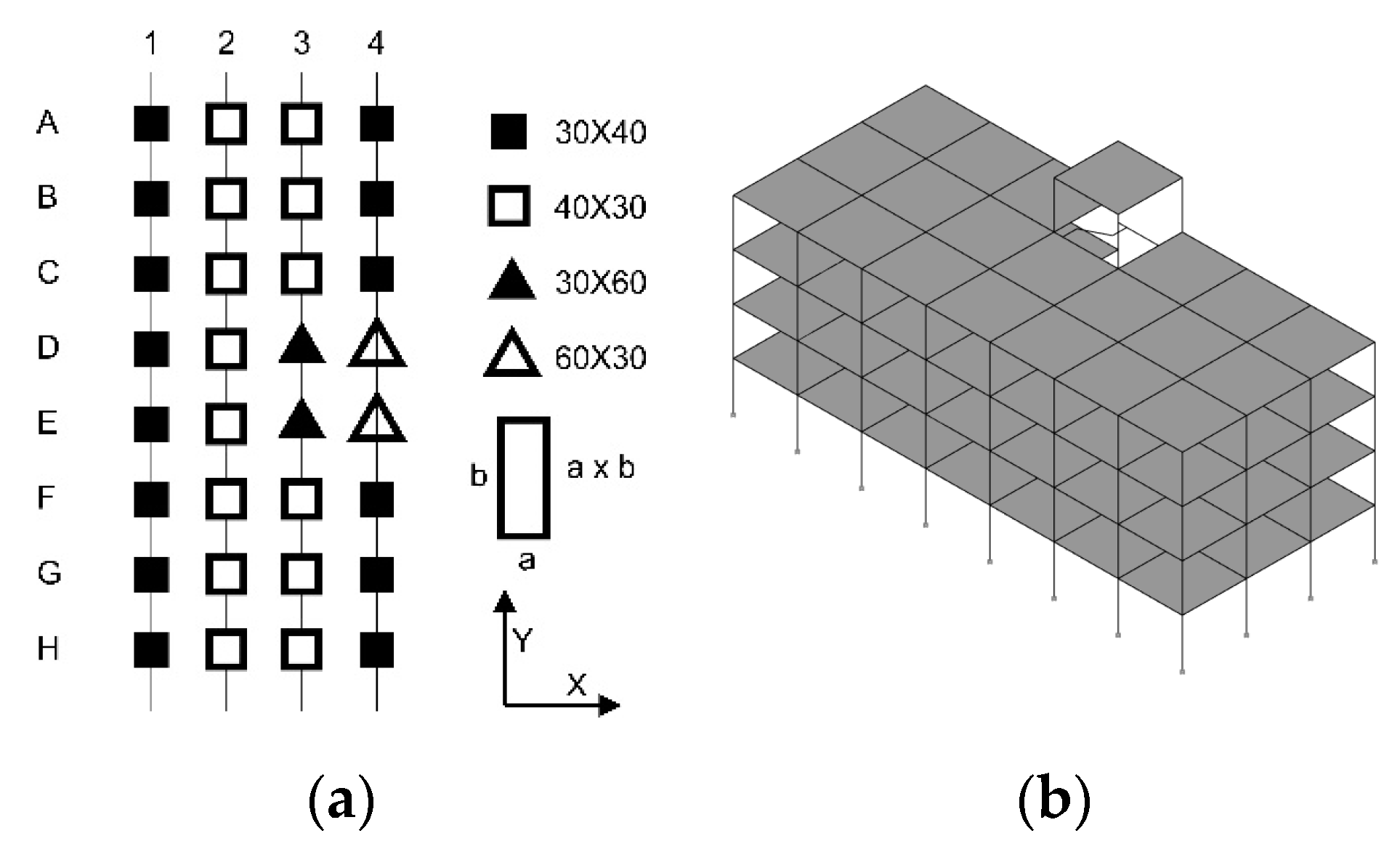
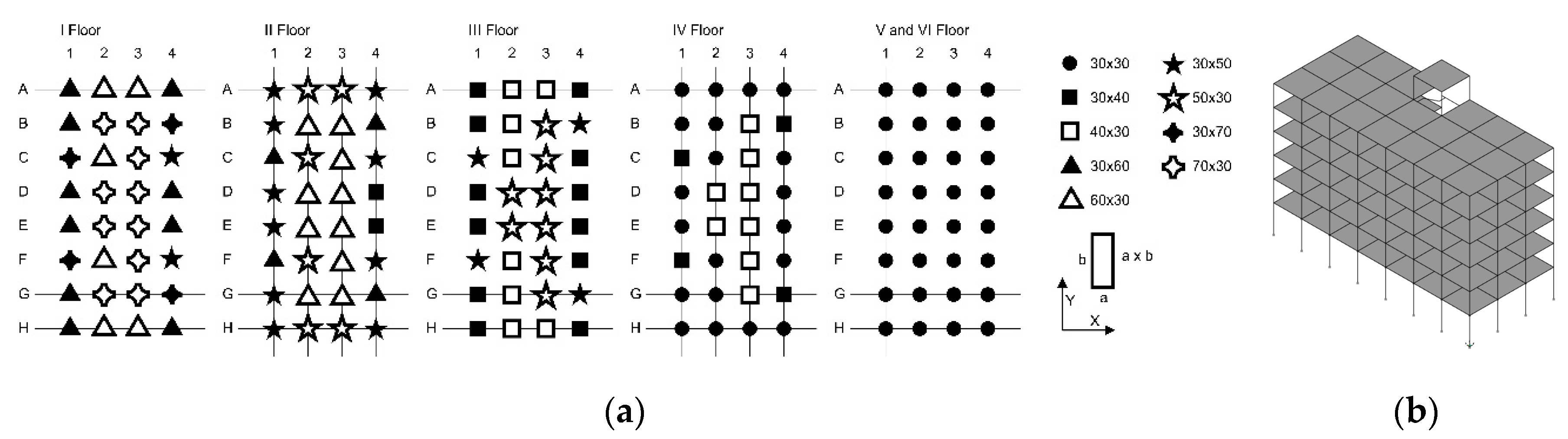
Type 3 is represented by a six-storey building, with decreasing size of the column cross-sections along the height and eccentricity between the CS and CM at each floor. The planar distribution of the cross section of the columns is reported for each floor in
Figure 16a, while
Figure 16b shows a scheme of the FEM model.
As it has been already foretold, for this building due to the contemporary presence of planar and vertical irregularities, both the frequencies and the modes of vibration were taken into account in the minimization procedure in order to reliably evaluate the stiffness correction coefficients. With the aim of proving the latter statement, the matrices MAC_Tp3A and MAC_Tp3B obtained, respectively including or neglecting the modal shapes in the objective function, are reported in the following:
The observation of the matrices clearly shows that the addition of the modal shapes is necessary in order to obtain accurate results.
The minimization of the described objective function provides for this building the following values of the stiffness correction coefficients: .
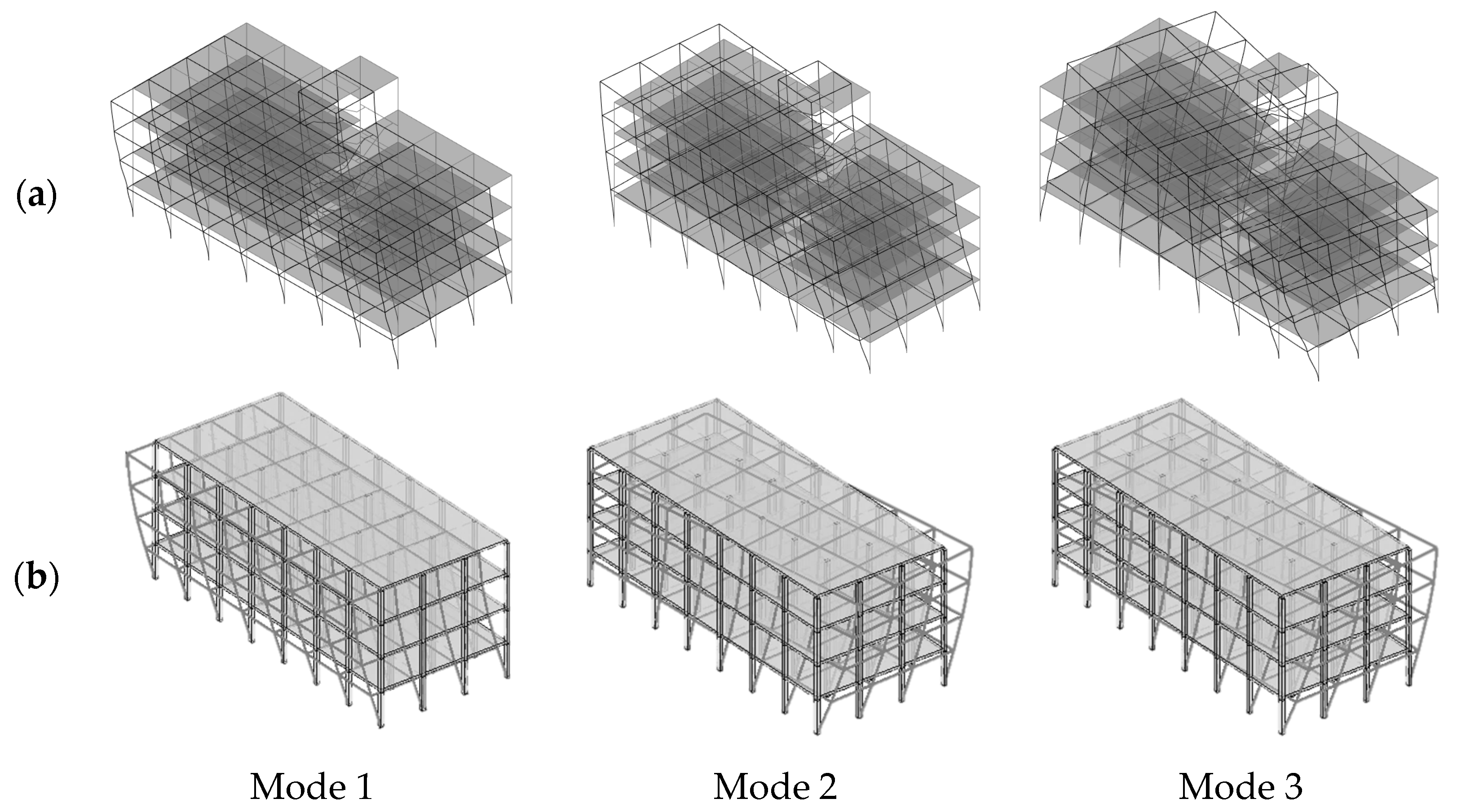
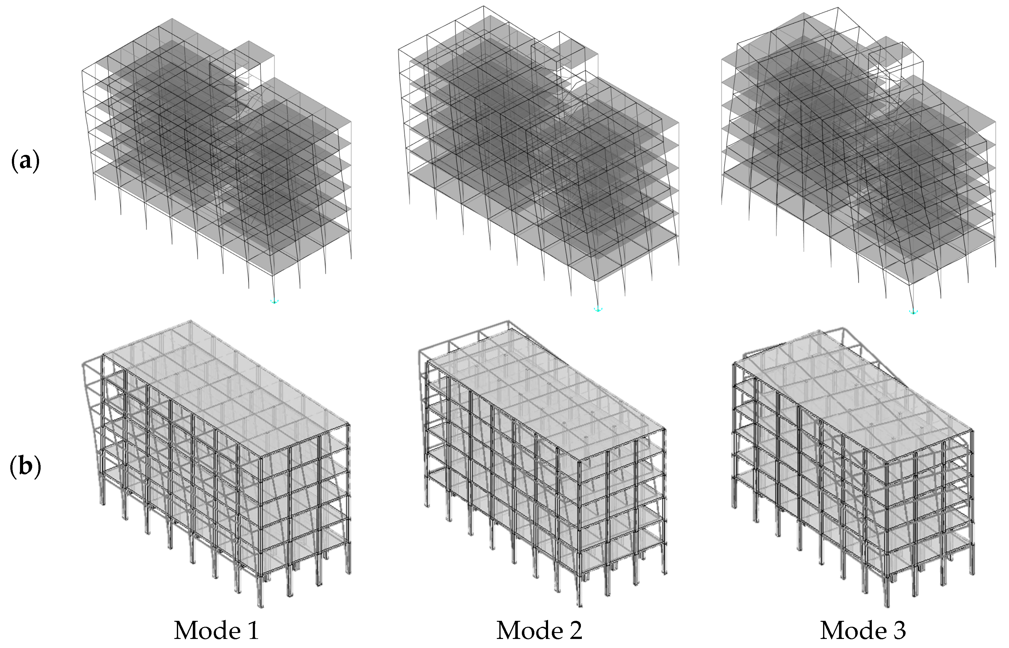
Table 4 and
Figure 17 compare the modal properties, periods and modal shapes, respectively, for the conventional FEM and the proposed beam-like model. From the comparison of modes of vibration, either graphical through
Figure 17 or numerical by means of the MAC_Tp3A matrix, it can be observed that the results for the two considered models show good agreement and confirm the reliability of the proposed approach.
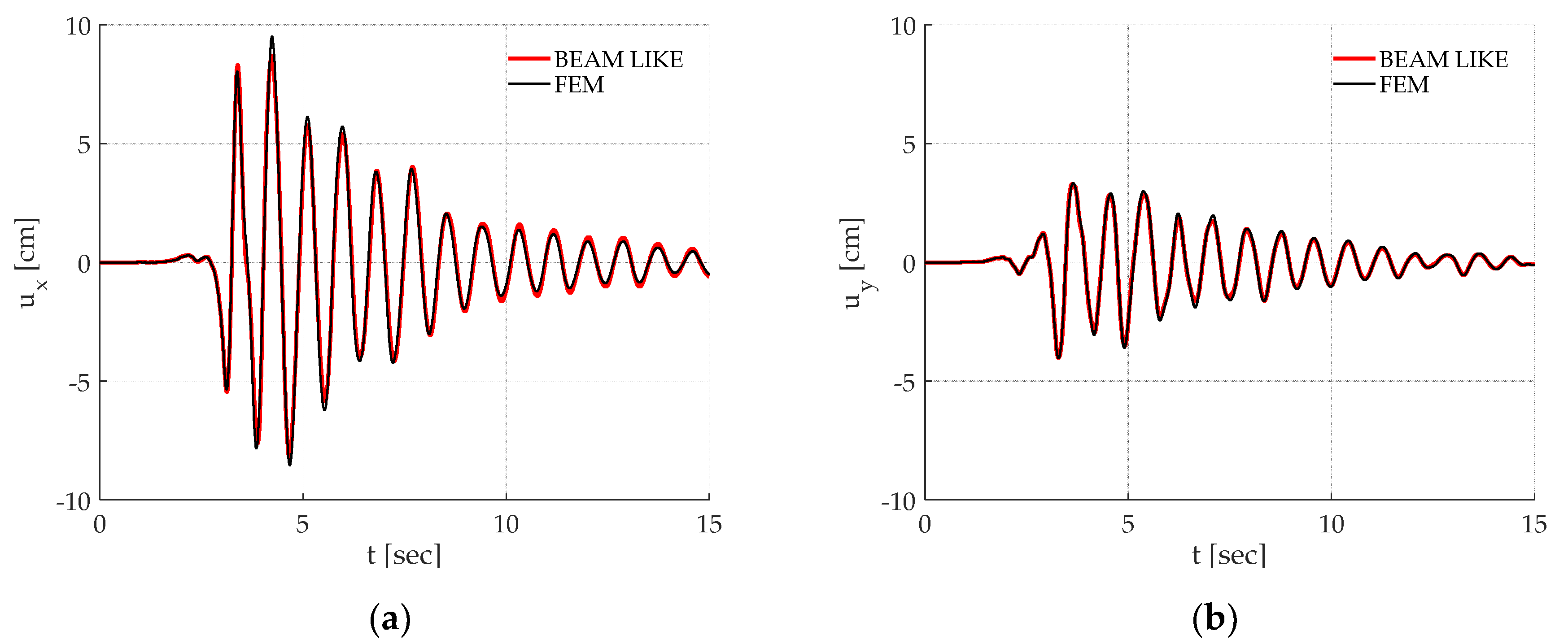
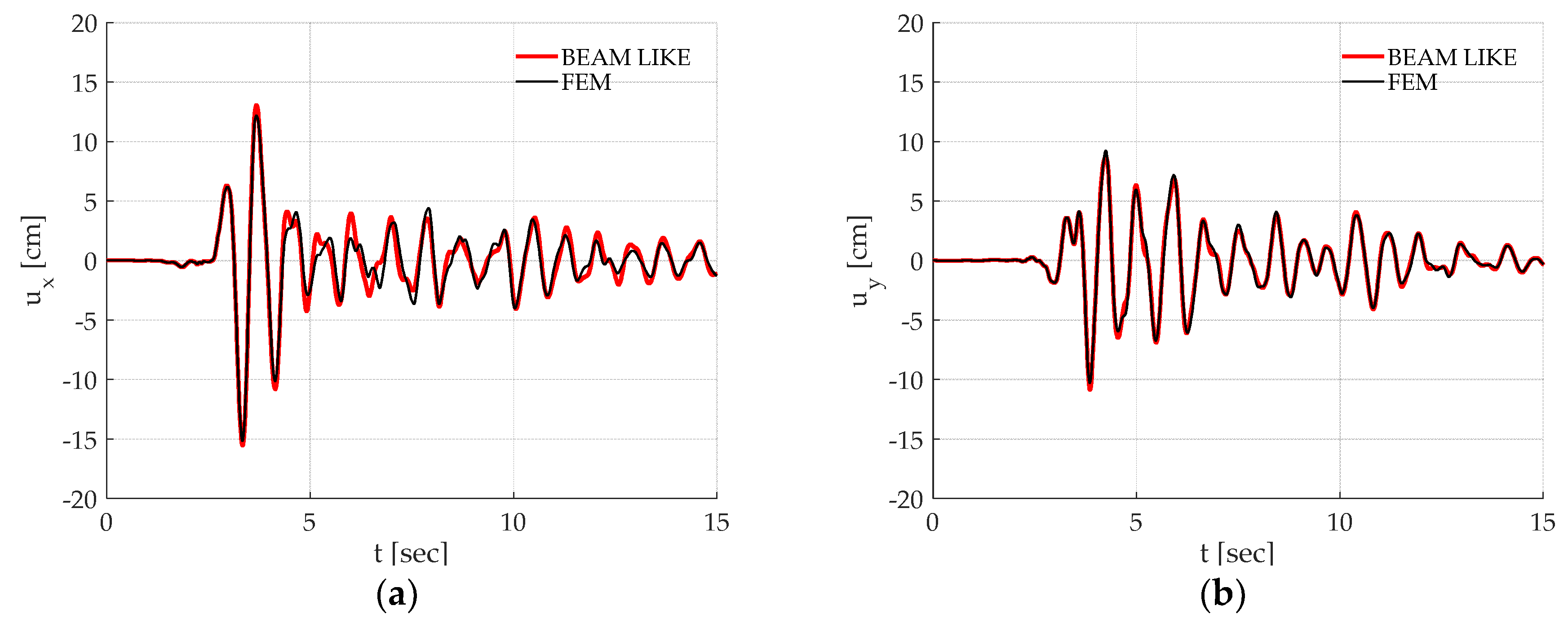
For this irregular building also, the time histories of the displacement components of the considered control point, shown in
Figure 18 and
Figure 19, and the maxima displacements at each floor reported in
Figure 20, are sufficiently accurate.
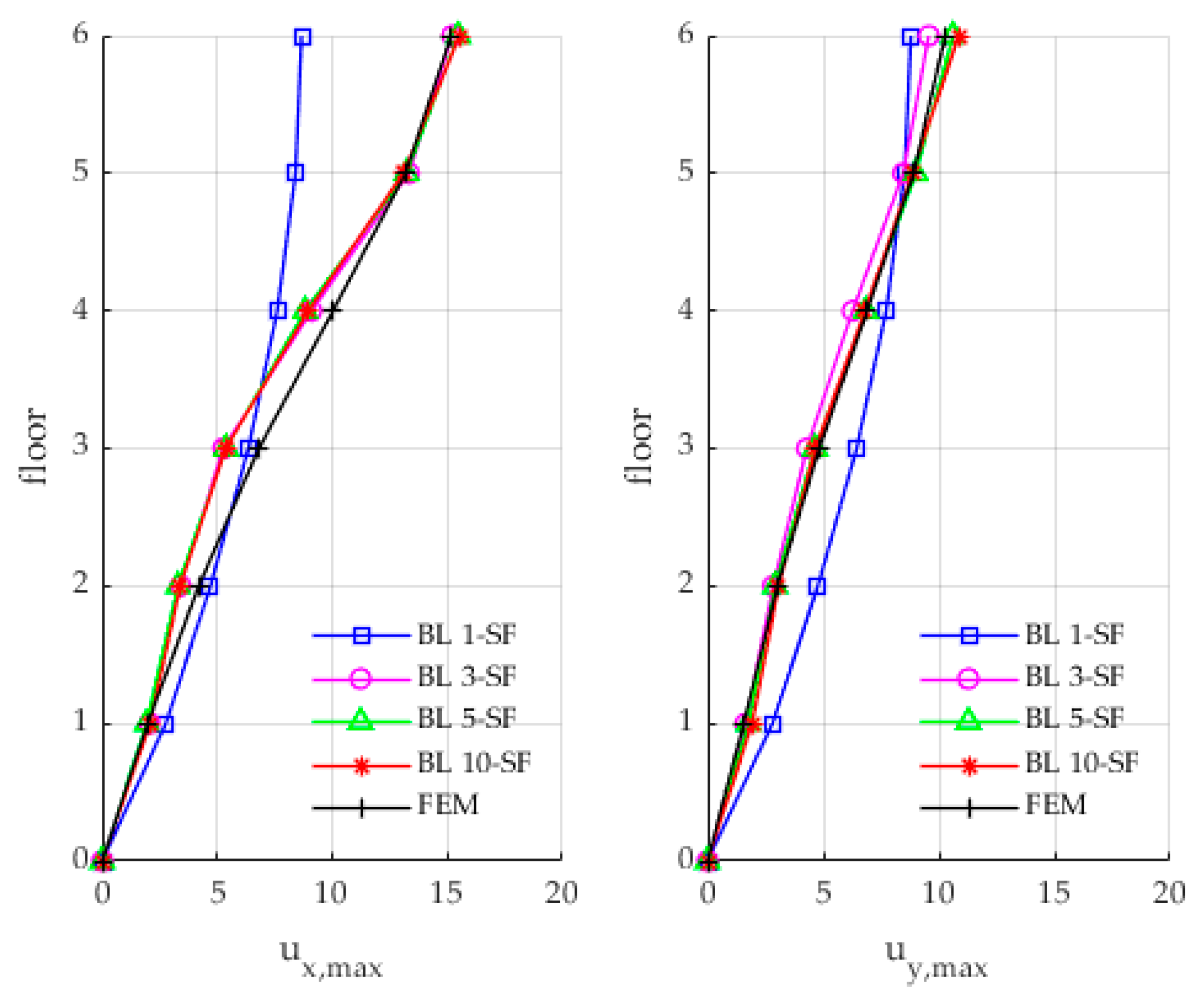
With the aim of investigating the influence of the number of Rayleigh–Ritz components on the seismic response of the beam-like model, some further numerical analyses were developed varying the number of modes of vibration considered in the discretization.
Figure 21 shows the maxima displacements of the control point at each floor of the Type 3 building, subjected to the L’Aquila earthquake, evaluated with a variable number of shape functions. As it can be clearly observed, the increase in the number of adopted shape functions allows to reduce the differences with respect to the results obtained through the FEM model.
4. Conclusions
The study proposes a beam-like model suitable for the schematization of real buildings that do not have a uniform mass and stiffness distribution along the height and are characterized by asymmetric plans.
The linear dynamic behaviour of the beam-like element was evaluated by discretizing the continuous model according to a Rayleigh–Ritz approach based on a suitable number of modal shapes of the uniform shear torsional beam clamped at the base. An optimization procedure was adopted for estimating the appropriate stiffness correction coefficients in order to take into account possible uncertainties in the structural parameters and the out-of-plane floor deformability. These correction coefficients were identified by minimizing the objective function that measures the difference between a fixed number of eigen-properties of the beam-like model and the correspondent target values. The latter represent the natural frequencies and the modes of vibration of the real structure and could be directly measured by means of dynamic tests. In the present paper, however, without limiting the general applicability of the proposed procedure, these target values were calculated by means of three-dimensional linear FEM models.
The proposed procedure was applied in the evaluation of the dynamic response of three multi-storey RC frames representative of residential buildings designed for vertical loads. Only the first three modes have been considered for calibrating the correction factors. The first two case studies report only one irregularity, either in the planar or in the vertical distribution of mass and stiffness. In the last analyzed building, both the planar and vertical irregularities are present. It is highlighted that an increase in the number of irregularities require the knowledge of more data in order to seek an appropriate set of correction coefficients for the stiffness of the building. The results reported in the applicative section show that, in spite of the simplicity of the proposed beam-like model and the small computational burden, satisfactory results were obtained. In particular, the frequencies and modes of vibration, time histories of the displacements of some control points and maxima displacement at each floor level of the 3D FEM models were compared to those calculated by means of the proposed beam-like model, showing, for all the considered buildings, good agreements.
Although the study is limited to the elastic range of the dynamic behaviour of beam-like structures, the obtained results show good accuracy, indicating the proposed approach has potential in modelling real buildings. The elastic model could either be useful in the definition of an operativity limit state index, based on ambient vibration, or represent the first step needed for the implementation of a powerful tool for the seismic assessment of urban areas with an extremely low computational burden.

 ,
, 


