
Assessment of Active Wheelset Steering System Using Computer Simulations and Roller Rig Tests


1
Department of Automotive, Combustion Engine and Railway Engineering, Faculty of Mechanical Engineering, Czech Technical University in Prague, 16000 Prague, Czech Republic
2
Department of Instrumentation and Control Engineering, Faculty of Mechanical Engineering, Czech Technical University in Prague, 16000 Prague, Czech Republic
*
Author to whom correspondence should be addressed.
Appl. Sci. 2021, 11(24), 11727; https://doi.org/10.3390/app112411727
Submission received: 26 October 2021
/
Revised: 23 November 2021
/
Accepted: 7 December 2021
/
Published: 10 December 2021
(This article belongs to the Special Issue Innovative Solutions for the Railway Sector: Design and Experimentation)
Abstract
:Featured Application
The design of innovative railway running gears providing reduced wear of wheels and rails.
Abstract
The paper is created within a project which aims to design a system of active wheelset steering for an electric four-axle locomotive. The wheelset steering system enables reduction in forces acting in the wheel-rail contacts in a curved track and consequently a reduction in wear and maintenance costs of both vehicles and rails is achieved. The project consists of three main parts: computer simulations, scaled roller rig experiments, and field tests. The paper is focused on the fundamental aspects of the first and the second part on the project. Track curvature estimation based on the rotation of the bogies towards the car body is proposed and assessed by computer simulations across varying track radiuses, vehicle speeds, and friction conditions. The scaled roller rig has been innovated in order to simulate bogie run in a curved track with uncompensated value of lateral acceleration and instrumented with a system of measurement of lateral wheel-rail forces. The experimental bogie has been equipped with systems of active wheelset steering and measurement of axle-box forces. The experiment setup, newly developed and applied systems of forces measurement and wireless signal transmission, and results of the first experiments are described in detail. Performed computer simulations and scaled roller rig experiments show that active wheelset steering is effective and practically implementable method of reducing guiding forces acting between railway vehicle wheels and rails in a curved track.
1. Introduction
Force interaction in between rails and railway wheels is one of the most important issues in the development of the new rolling stock. The forces in the wheel-rail contact, and their mutual relationship, must meet the safety against derailment criteria first specified by Nadal [1] which are still the subject of a number of obligatory standards [2,3]. However, todays’ effort to build an economic and environmentally friendly railroad brings a general and sustained demand to reduce wheel-rail contact forces below legislative limits as much as possible. Particular attention is paid to the lateral component of wheel-rail contact forces during passing a curved track, also called guiding forces. Conventional methods of reduction in guiding forces are based on the optimization of suspension characteristics [4], or on mechanic or hydraulic linkages between the various components of the running gear. As the capabilities of conventional methods are increasingly encountering their limits, ideas of the utilization of active controlled elements in the wheelset guidance and railway vehicle suspension occur. A number of theoretical studies describing various strategies for controlling active elements in railway running gears and proving by means of computer simulations [5,6,7] or experimental results [8] their possible benefits for reduction in guiding forces have been published. One of the first practical utilization of such systems are active yaw dampers developed by Liebher and offered as an option for Siemens Vectron locomotives [9] (Figure 1).
Nevertheless, these systems are still rare on vehicles in ordinary railway traffic and the utilization of modern approaches for the reduction in guiding forces is a topical issue addressed by many railway vehicle manufacturers and university research teams.
This article describes the results of the introductory part of the project, the aim of which is to develop a system of active wheelset steering for an electric locomotive to reduce the magnitude of guiding forces in track curves. Section 2 asses the contribution of existing systems for the reduction in guiding forces and compares them with active wheelset steering. The main goal of this comparison is to gain arguments for the development of the active wheelset steering system. The control algorithm for steering wheelsets is not addressed in the article. However, it is assumed that the necessary input of the controller will be information about the actual curvature of the track. Section 3 deals with methods of track curvature detection and proposes a method for estimating track curvature which is based on the measurement of the rotation of bogies towards the car body. It is assumed that a scaled roller rig will be used to verify and demonstrate the results of mathematical simulations and to assess different wheelset steering algorithms in the following stages. Therefore, the Czech Technical University roller rig has been significantly innovated recently. Section 4 presents the results of initial experiments on this device, which were aimed at verifying the new functions of the roller rig and the experimental bogie that are necessary to perform experiments with active steering of wheelsets and to assess its impact on the magnitude of forces in wheel-rail contact.
2. Materials and Methods
In order to compare the effectiveness of individual methods for reducing guiding forces, a simplified multibody simulation (MBS) model of an electric locomotive has been created (Figure 2). The model consists of 7 rigid bodies (car body, 2 bogie frames, and 4 wheelsets) that are connected by linear force elements. Wheel-rail contact respects non-linear characteristics of S1002 wheel and UIC 60 rail profiles, forces acting in the wheel-rail contacts are calculated using FASTSIM method [10]. The main parameters of the simulation model are listed in Table 1.
Using this model, simulations of a vehicle running at a low speed on the curved track of a radius R = 150 m were performed, considering the friction coefficient in the wheel-rail contact f = 0.4. The quasistatic value of guiding force in a constant curvature track without irregularities Yqst was evaluated on all wheels. A vehicle setup and parameters has been sought in which the value of Yqst is minimized. The maximum value of Yqst is typically reached on the outer wheel of the first wheelset. Simulations were performed for 6 different vehicle configurations. The first five configurations represent the solutions used on existing electric locomotives, the sixth configuration the system under the development.
- STD—Standard, the suspension parameters correspond to the standard 4-axle electric locomotive with flexi-coil type secondary suspension.
- YFS—Yaw Flexible Suspension, Figure 3a. The characteristics of the primary suspension and wheelset guidance are modified in order to reduce the yaw stiffness of the connection between wheelsets and bogie frame.
- MBC2—Mechanical Bogies Connection Type 2, Figure 3c. Mechanical connection of bogie frames by a mechanism. This method works on the similar principle such as MBC1, but it has less space demands. Thus, MBC2 can be utilized also on asynchronous locomotives, which have usually a large transformer located between the bogies [11].
Figure 3.
Vehicle configurations. YFS (a), MBC1 (b), MBC2 (c), AYD (d), and AWS (e).

The parameters of mechanical bogie connections MBC1 and MBC2 (i.e., stiffness and preload of coupling elements) were optimized in order to achieve the best performance in a 150 m radius of a track as well as the force produced by AYD actuators and the wheelsets yaw angle for AWS. Figure 4 and Table 2 thus expresses the theoretical maximum possible effect of reducing the guiding forces, which can be achieved by individual methods.
It is important to note that:
- Contribution of mechanical bogie connections MBC1 and MBC2 to the guiding force reduction will be lower than calculated values of 23 percent for MBC1, respectively 10.5 percent for MBC2. The parameters of mechanical bogie connections should be compromised in the wide range of curve radiuses.
- For AYD, the impact of forces in the actuators on the secondary suspension deflections was not taken into an account. To avoid undesired large deflections of secondary suspension in the lateral direction and transmitting forces via lateral bump-stops, the power of the actuators would probably have to be lower than considered in the simulation. Consequently, a reduction in guiding forces will be lower than the calculated 25.7%.
- The highest reduction in guiding forces (75%) shows YFS. However, such reduction is achieved for zero value of the yaw stiffness of the wheelset guidance which drastically affect the stability and lower the maximum speed of the vehicle.
In the view of the above, AWS seems to be very promising method of reducing guiding forces. Therefore, the project, with the aim of design a system of active wheelset steering for an electric four-axle locomotive, was launched. The project is divided into the three main stages:
- I.
- computer simulations;
- II.
- scaled roller rig experiments;
- III.
- on track tests.
The goal of Stage I is composing and verification of the detailed simulation model including wheelset steering actuators and control loop and optimize the wheelset steering control algorithm considering various vehicle speeds and track conditions.
The Stage II is focused on the verification of computer simulations and demonstration of the benefits of AWS using a scaled laboratory test device [16] (Figure 5).
The Stage III includes implementation of AWS system on an existing locomotive and performing track tests.
3. Computer Simulations
The idea of actively controlled wheelsets steering is not entirely new. Various wheelset steering algorithms have been already proposed and tested by computer simulations [17]. Feed forward approach will be applied in this study. This method is based on the control of the yaw angle of both wheelsets with respect to the bogie frame. This is achieved by controlling the position of actuators that acting in the longitudinal direction between the bogie frame and axle-boxes. The required actuator position, determining yaw angle of wheelset, is a function of the track curvature. The advantage of this method is a relative simplicity, as the control algorithm does not require knowledge of time variable and difficult-to-measure inputs such as actual wheel profile or creep coefficients. For the practical implementation the two fundamental tasks have to be solved:
- detection of the actual track radius;
- control algorithm of wheelset steering.
Computer simulations are planned in several steps. In the initial phase a simplified vehicle model was used, and a large number of simulations was performed in order to compare various approaches of detecting the track curvature and the algorithms for controlling wheelset steering. The performance of selected solution will be consequently assessed by detailed simulation model of an electric locomotive. The simulations focused on the detection of the track radius using simplified vehicle model are described in this study, the simulations focused on the comparison of control algorithms, as well as simulations with detailed vehicle model, will be published in subsequent papers.
Track Radius Estimation
In general, two main approaches for the track radius estimation exist:
- Utilization of the track map and detecting the position of the vehicle on the track. This method assumes the knowledge of the curvature along the track, which must be available to the controller, for example in the form of a look up tables. The position of the vehicle on the track could be detected by GPS navigation or by measurement of wheelset revolutions. Integration wheelset revolutions is rather inaccurate due to slips in wheel-rail contacts and unknown value of exact wheel radius. However, it can be refined by track marks at certain known positions. Most of the railway tracks are already equipped with such marks, for example balise transmission modules of European Train Control System could be utilized for this purpose.
- Estimation of the track radius using on board sensors.
Although vehicle positioning systems based on the GPS navigation exist and achieve continuously improving parameters in terms of accuracy and reliability, estimation of track radius by of onboard sensors was finally chosen. The main advantages of an onboard system are:
- independence of GPS signal which can be difficult to reach in urban areas with high buildings around the track, deep valleys, or in tunnel sections;
- independence of wheel radius measurement or estimation;
- independence of the track map. This gives the possibility to operate the vehicle on any track without the need to provide the controller by track data, which can be very important in the event of unexpected obstacles on the track, lockouts, etc.
Due to the above reasons the estimation of the track radius by onboard sensors is proposed in this study. As an input for the tack radius estimation the rotation angle around vertical axis of the bogie towards the car body can be used. Assuming that the wheelsets follow the track centreline, the track curvature can be expressed by:
where is track radius, is track curvature, is bogie distance, and is angle of rotation of bogies towards the car body, see Figure 6.
Equation (1) is fully valid only when the whole vehicle is in a curved track of a constant curvature. Figure 7 shows simulation results of a vehicle negotiation of a track curve. It can be seen that in the transition track section, where the track curvature changes, the track curvature estimated by Equation (1) lags behind the actual track curvature on the leading bogie, whereas track curvature estimated on trailing bogie is ahead.
This phenomenon could be considerably eliminated by the method proposed in [18]. The method utilizes not only the angle of bogie rotation towards the car body , but also its derivative:
where is time derivative of and is vehicle forward velocity. Figure 8 shows track curvature estimation by Equation (2) in curve.
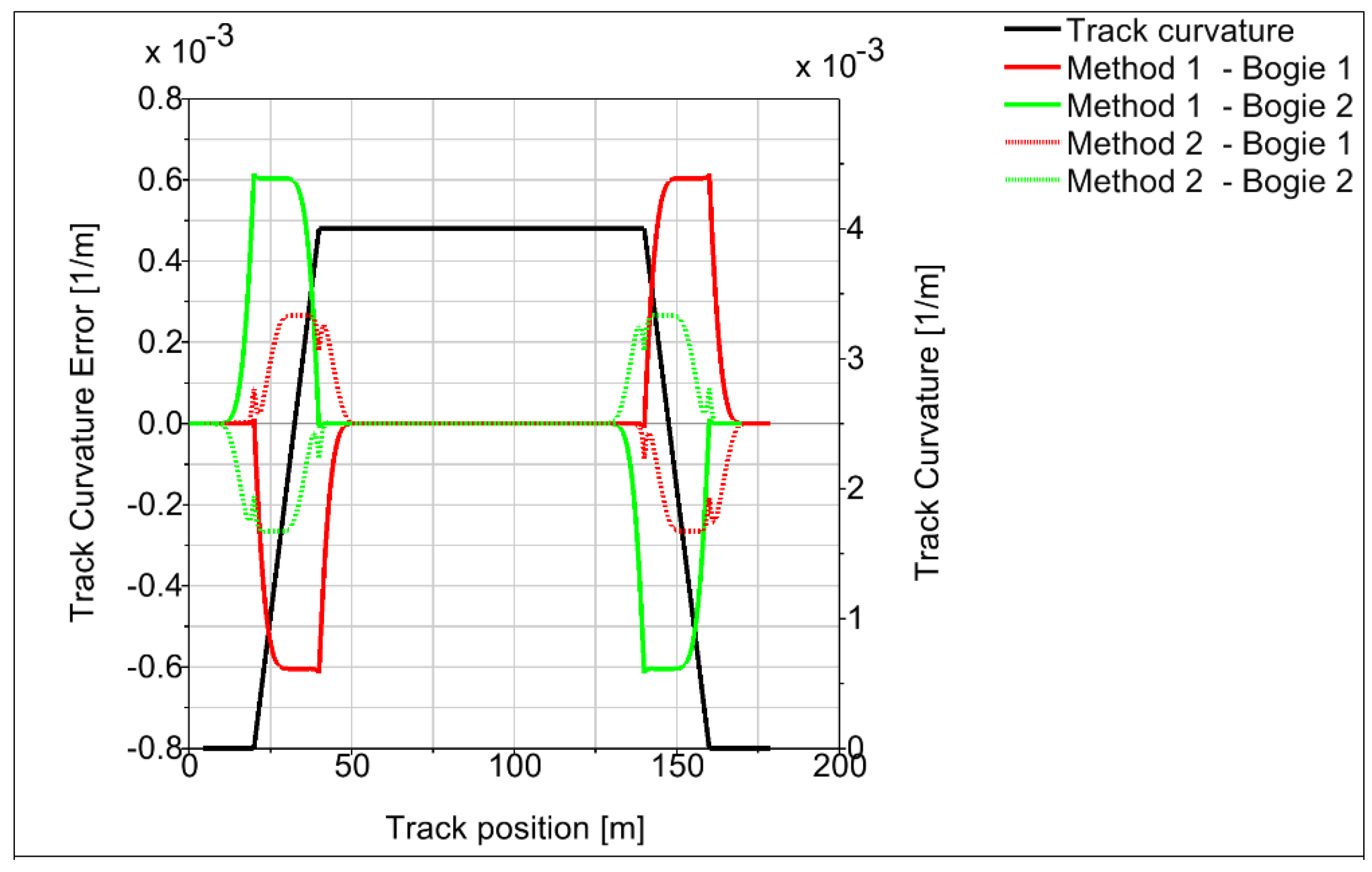
The curvature estimation leg is virtually eliminated, although small overshoots occur around points where the second derivative of track curvature changes. The error of the track curvature estimation for both calculation algorithms is plotted on Figure 9. The algorithm according Equation (2) reduces the track estimation error in the transition track by more than 50% compared to the Equation (1). The track estimation error of Equation (2) in the transition track is less than 7%.
One problem is that the assumption of wheelsets that are perfectly aligned with the track centreline is not fully satisfied. A wheelset can move towards the track centreline in the lateral direction within the gauge clearance. Consequently, the angles of rotation of the first and second bogie differ, and vary in dependence of many parameters such as wheel and rail profiles, creep coefficients, value of unbalanced lateral acceleration, or torque caused by lateral deflection of flexi-coil springs. Typically, the leading bogie exhibits smaller angle and trailing bogie larger angle than is expected by ideal alignment of wheelsets and the track centre. The maximum deviation of the angles of rotation can be expressed by:
where is gauge clearance and is the wheelbase of the bogie. For the rail profile UIC 60, rail inclination 1:40, wheel profile S1002, and nominal values of wheelset and rail gauge is the gauge clearance . Wheelbase of the locomotive under consideration . According to Equation (3), it is then . Thus, due to uncertain lateral position of wheelsets the error of estimated track curve curvature can reach tens of percent (see Table 3).
In order to determine the probable position of the wheelsets within the gauge clearance the set of simulations was performed. The simulation parameters are summarized in Table 4, where is superelevation of rails and is the value of uncompensated lateral acceleration.
The simulations were performed for the ideal track without irregularities and friction coefficient 0.4. The quasistatic value of bogies rotation towards car body were observed. Based on the bogie rotations the track curvature was calculated using Formula (2) and compared to the real track curvature. The results are shown of Figure 10.
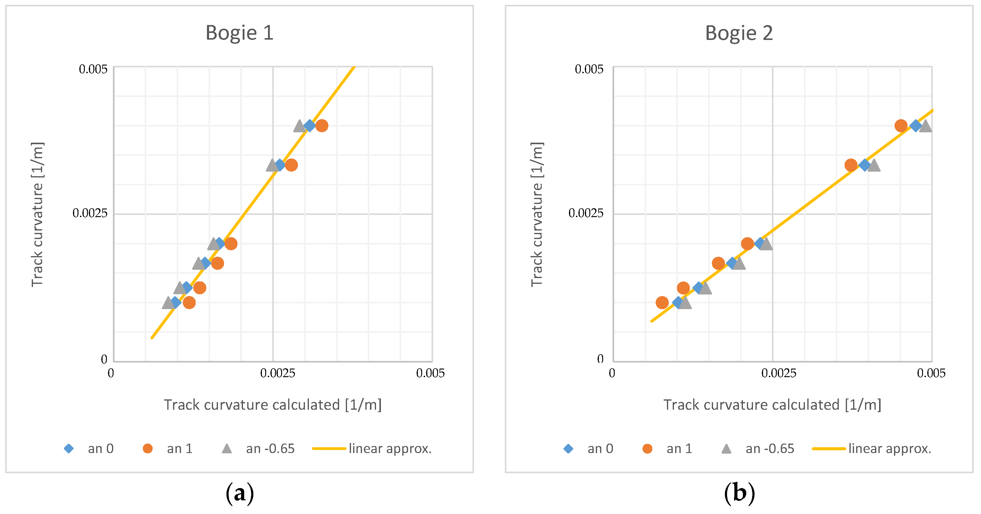
The results confirm underestimation of track curvature on leading bogie and overestimation of track curvature on trailing bogie. This phenomenon is more significant for negative values of uncompensated lateral acceleration, i.e., in low speeds. In order to eliminate it, a linear approximation of relation between calculated and real track curvature was constructed. The approximation is shown on Figure 10 by yellow curve and mathematically can be expressed by:
where is real track curvature, and are track curvatures calculated on leading and trailing bogie, respectively, and , , , and are coefficients of the linear approximation.
Combining the relations Equations (2) and (4) the final relation for calculation of the track curvature is obtained:
Track curvatures obtained by Formula (5) for the set of 18 simulations are summarized in Table 5.
The maximal error in track curvature calculation is around 25%. However, the maximal error values are obtained in large curve radiuses. The system of active wheelset steering is aimed especially for the small and very small radius curves, which radius is typically in the range from 250 m to 600 m. In this range, the error of track curvature calculation is under 14%.
The track conditions vary in time due to the wear, weather, rail pollution, and other factors that significantly influence the value of friction coefficient in the wheel-rail contacts. All above simulations were performed in dry rail conditions with friction coefficient 0.4. To assess the influence of the friction coefficient to track curvature estimation a set of simulations for friction coefficient 0.15 was completed. The results are summarised in Table 6.
The results show that for the low value of friction coefficient, the precision of the track curvature calculation is decreased. The maximal error reaches 28% in large radius curves and 25% in small and very small radius curves. This relatively high error is obtained in runs with large positive uncompensated lateral acceleration, runs № 10 and 11.
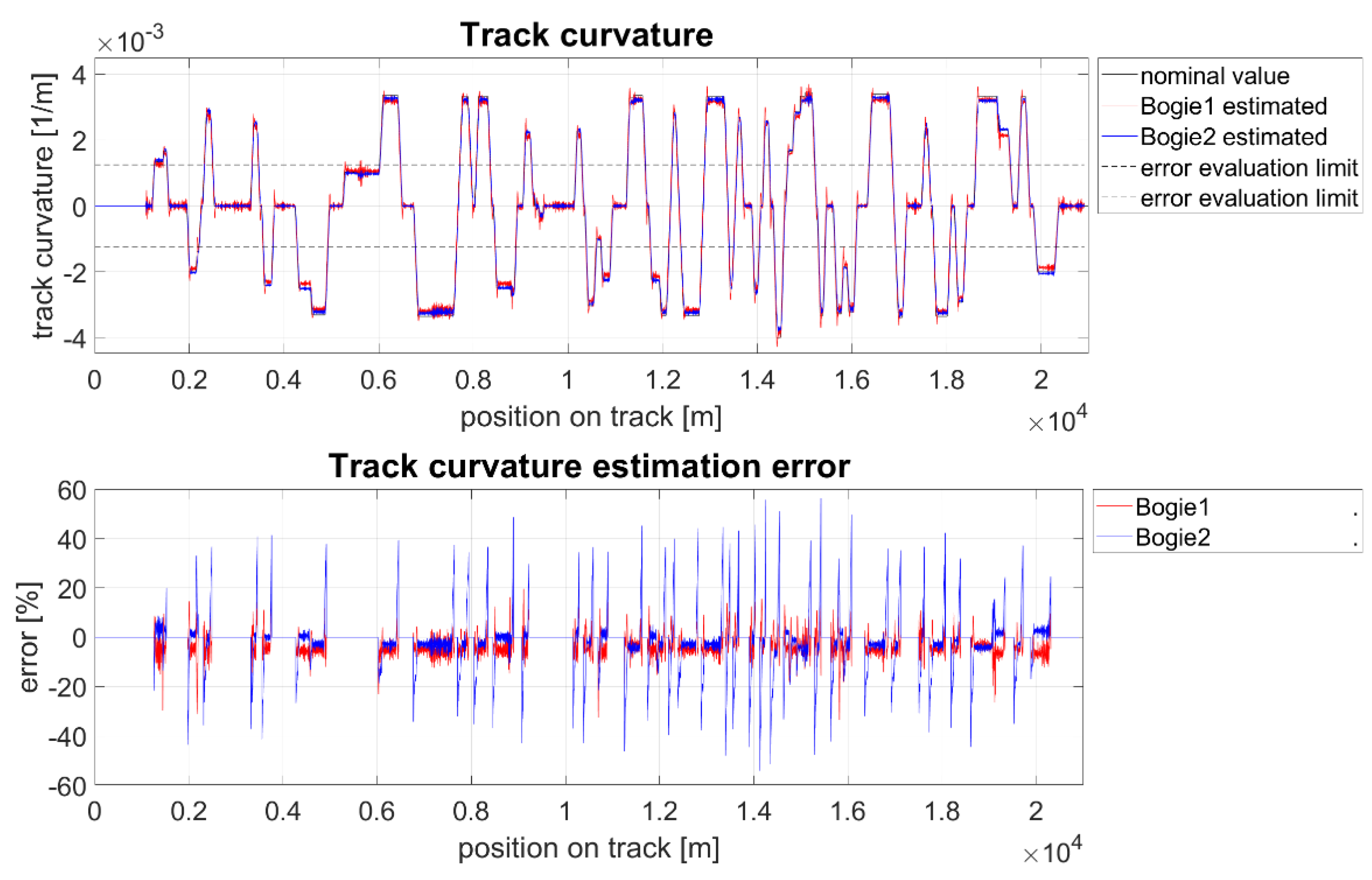
The section of the Letohrad–Lichkov line (Figure 11) was chosen as the test track for assessing the behaviour of the proposed track curvature estimation algorithm. This track is characterized by a large number of consecutive curves and is also often used during test runs of new types of rail vehicles. The track was modelled including the measured track irregularities that were obtained by track geometry measurement.
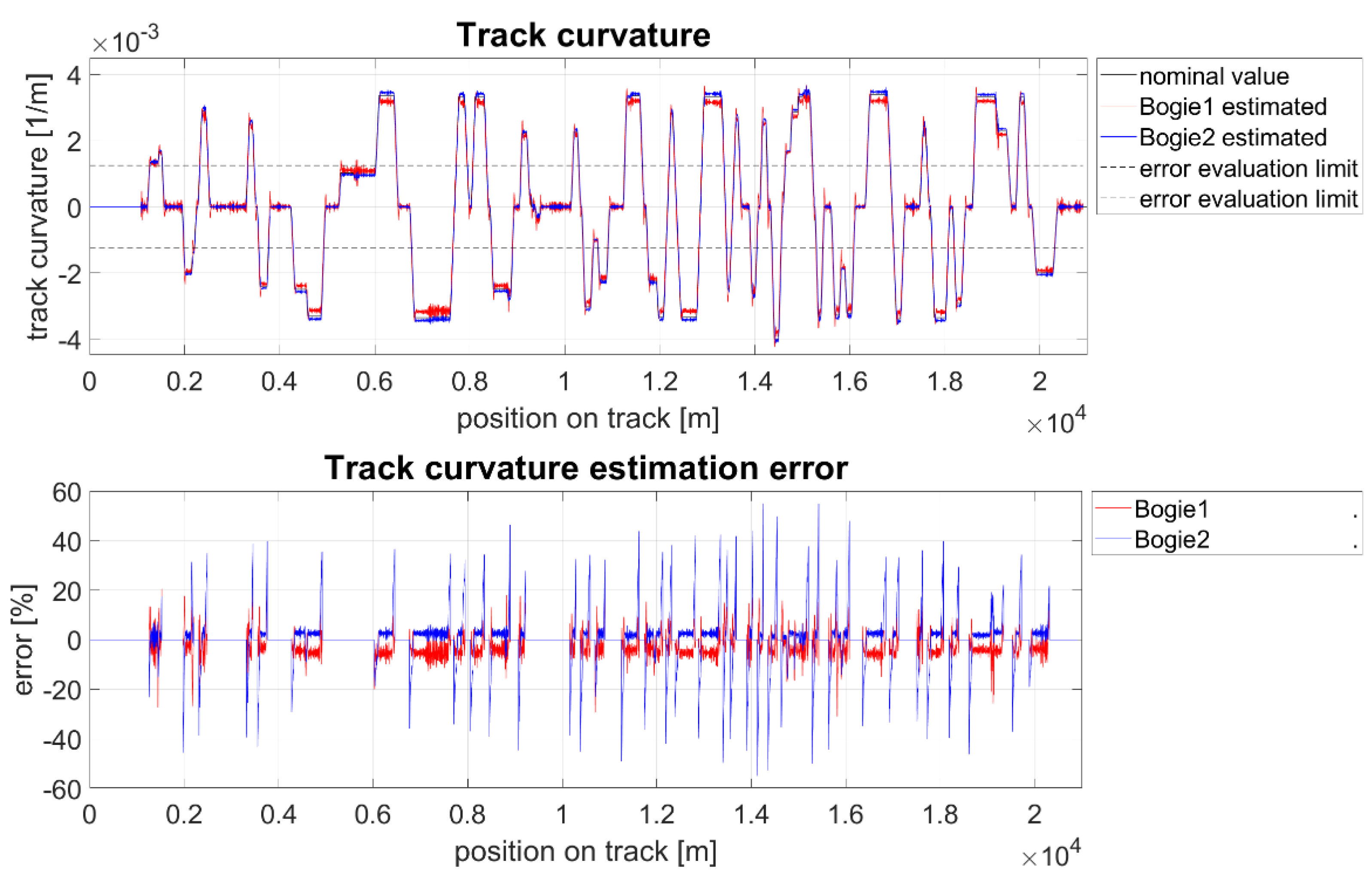
The simulations were performed at the vehicle speed of 80 km/h for two values of the friction coefficient in wheel-rail contacts f = 0.4 (Figure 12) and f = 0.15 (Figure 13). The error between the estimated and the actual value of the track radius was evaluated for the both bogies in curves with an absolute value of track curvature greater than 0.00125 m−1 which corresponds to track radiuses less than 800 m.
The simulations show a very good agreement between the calculated and the actual value of the track curvature. In constant radius curves, the error is less than 10% regardless of the friction coefficient. In transitions sections, the error on the rear bogie occasionally exceeds 50%. However, errors that exceed 20% occur only for a very short time. This phenomenon thus can be eliminated by signal filtering, or by track curvature estimation performed by measurement on leading bogie only and utilizing it for the wheelset steering controllers on both bogies.
4. Scaled Roller Rig Experiments
Prior to the first field tests of active wheelset steering system, it needs to be thoroughly stationary tested. Roller rigs can be advantageously used for these tests, as they allow testing of vehicle running behaviour in laboratory conditions, where it is possible to simulate extreme situations without a risk of railway accident [19,20]. The principle of roller rig is in the replacement of a track by rotating rollers with a rail profile on their circumference. The tested vehicle is longitudinally fixed. Nevertheless, the creep conditions and forces in the wheel–roller contact points are analogical to the conditions in wheel-rail contacts of a vehicle running in a real track. In the development of fundamentally new systems of rolling stock running gears scaled experiments are often performed [19], as this considerably reduces the cost of carrying out the experiments. Both scaled test tracks [21,22] and scaled roller rigs are used [23]. In order to perform laboratory tests for the assessment of the impact of AWS on guiding forces a scaled roller rig and experimental two-axle bogie will be utilized.
4.1. Roller Rig Setup
The CTU scaled roller rig and experimental bogie have been considerably improved in order to simulate bogie negotiation of an arbitrary shaped track and to measure force interaction between the vehicle and the track. The rig capability of the simulation curved track conditions has been extended by simulation of the uncompensated lateral acceleration. It is based on tilting of the entire rig [24]. The main frame of the rig is supported on four rollers (Figure 14). Thus, the CTU roller rig is capable to simulate vehicle run in straight, transition, and constant curvature track up to radius of 15 m and rail cant deficiency up to 200 mm.
Special attention was paid to measurements of forces in the wheel–roller contacts and between wheelsets and bogie frame. Lateral components of the forces acting in the wheel–roller contacts are measured by strain gauge measurement of roller disc deformation [25]. The own telemetry system of wireless signal transmission from the rotating roller has been developed (Figure 15) [26].
The instrumented rollers have been calibrated by loading by directly measured lateral force that was gradually performed at 16 points on the roller. The maximum error is 2.5% in the range of 0.1–1 kN. Although the roller rotates in the speed up to 1000 RPM, the calibration constants are not influenced by rollers speed. The measured signal is wirelessly transmitted in 1 kHz sampling rate to the standard PC and further processed in LabView software. The signal transmission is realized independently for each roller, time synchronization of the signals is achieved by global positioning system (GPS) clock signal. The wireless signal transmission has been broadly tested; the number of lost samples is less than 0.05%. The measured signal is in parallel saved without lost samples to the memory card which is attached to the transmitter on the roller.
4.2. Experimental Bogie Setup
The experimental bogie is 1:3.5 scaled, but it does not correspond to any specific bogie of a real vehicle [27]. Its design is based on the goals of experimental research. In order to achieve high geometrical accuracy, most of the main structural parts are made of aluminium alloy by CNC machining. The connections of the mutually movable components are provided by roller and linear roller bearings; dry friction joints are avoided.
4.2.1. Wheelset Steering Mechanism
The wheelsets are steered by an actively controlled steering mechanism (Figure 16). The actuator is a permanent magnet synchronous servomotor (item 1) with rated torque 2.5 Nm. The actuator torque is transmitted via toothed belt (item 2) to the steering rod (item 3) and then to the wheelset by pair of linkages (item 5). Each wheelset is controlled independently to a desired value of yaw angle between wheelset and bogie frame by analogue voltage signal connected to the servomotor controller.
4.2.2. Axle-Box Forces Measurement
The experimental bogie is equipped with a system of measurement axle-box forces, i.e., forces transmitted between axle-boxes and bogie frame. Forces between each axle-box and bogie frame are transmitted via a stirrup (item 8 on Figure 16) which was optimized for the strain gauge placement and serves as 3-axis load cell. Each stirrup is instrumented by 36 strain gauges connected in 3 Wheatstone bridges (Figure 17). Thus, independent measurement of longitudinal, lateral, and vertical component of axle-box force is achieved [26].
The systems of wheel–roller contact force measurement and axle-box forces measurement has been successfully implemented, calibrated, and tested on the rig.
4.3. Setup of Experiments
The main goal of the first experiments was to verify the function of the simulation of the curved track, the test of active wheelsets steering and position control, while verifying the systems of measurement of axle-box forces and guiding forces. The two types of experiments were performed:
- Vehicle run in superelevated straight track. During this test, the wheelset steering was switched off, the bogie behaved as a standard passive suspension bogie. Straight track was simulated, whilst the rail superelavation p was continuously changed from zero to p = 28.6 mm (p = 100 mm. in a full scale).
- Test of active wheelset steering. These tests were conducted in a constant curvature track of radiuses corresponding to R = 300, 400, and 500 m in a full scale. The yaw angle of both wheelsets towards the bogie frame was changed in several steps. Both wheelsets were controlled to the same position, but in the opposite orientation.
4.4. Results of the First Experiments
4.4.1. Vehicle Run in Canted Straight Track
The cant angle of the track β could be expressed by:
where 2s is the distance of the rails in the lateral direction and p is superelevation of rails. Then, the lateral acceleration an is given by the component of the gravitational acceleration as:
Lateral force Fy acting on mass m is proportional to the rail superelevation by formula:
The results plotted on Figure 18 are fully consistent with above assumption. The red line shows the sum of the lateral component of axle-box forces across all four wheels, whilst the black line shows the sum of wheel-rail guiding forces. Both are proportional to the superelevation of rails. The difference between them corresponds to the mass of wheelsets.
4.4.2. Test of Active Wheelset Steering
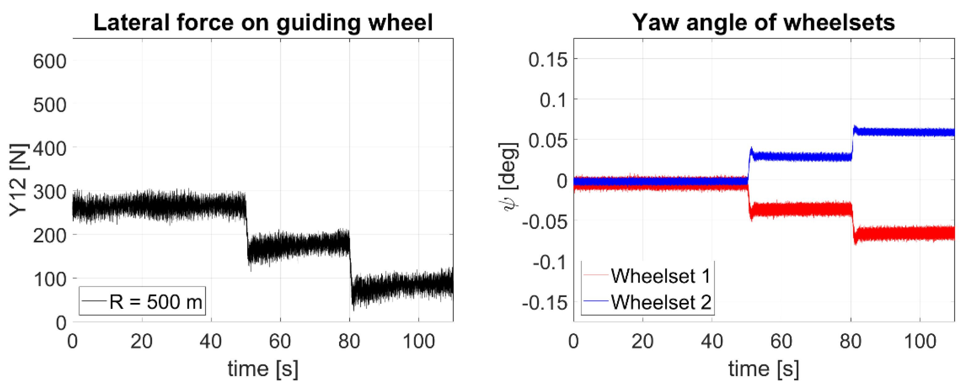
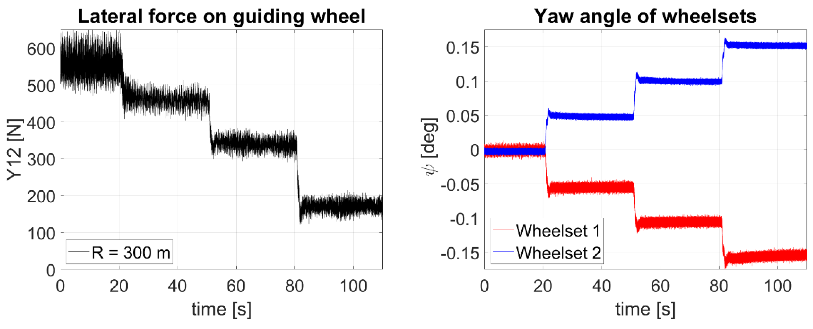
The test of active wheelset steering showed the functionality of wheelset steering mechanism and capability to steer both wheelsets to the desired yaw angle towards the bogie frame and conduct experiments on order to confirm theoretical assumption of the influence of wheelset steering on the guiding forces. The measurements were conducted in the three constant curvature track radiuses corresponding respectively to the 300, 400, and 500 m in the full scale. An uncompensated lateral acceleration was 1 ms−2 for all three measurements. At the beginning of the experiment, a bogie with rigidly guided wheelsets was simulated. Subsequently, both wheelsets were steered several steps. The magnitude of the wheelsets yaw angles towards the bogie frame was the same on both wheelsets, but in the opposite orientation. The plots on Figure 19, Figure 20 and Figure 21 show the time development of guiding force on the outer wheel of the first wheelset which exhibits the highest value of guiding force of all wheels of a bogie.
A strong dependence of guiding forces on the yaw angle of wheelsets and possibility to considerably reduce the guiding forces by active wheelset steering were confirmed. With the increasing value of the wheelset yaw angle, guiding force fell below 40% of its original value. The most significant benefit of active wheelset steering is in terms of the absolute magnitude of the decrease in guiding forces is in tight curves of a small radius.
5. Results Summary
Computer simulations show that active wheelset steering is a very promising, practically implementable, method that could bring reasonable decrease of guiding forces on modern railway vehicles. For the practical implementation of active wheelset steering system is essential to provide the controller by the actual track curvature. The track curvature calculation method based on the measurement of yaw angle of bogies towards the car body has been proposed. The advantage of such method is independence on the track map and system for the positioning of the vehicle on the track. However, the bogie rotation varies due to the varying position of the wheelsets within the gauge clearance and causes error in the track curvature estimation. Therefore, the sets of simulations for varying track radius, uncompensated lateral acceleration, and friction condition were performed. The actual track radius and track radius calculated using bogie rotation were compared. This comparison was then used for linear approximation formula that decreases track curvature estimation error. The method shows the maximal error of track curvature calculation in small and very small track radiuses about 14% in dry track conditions and 25% in low friction track conditions. The method of detection of the track curvature was successfully tested by simulating the vehicle running on the real more than 20 km long track section with irregularities. By this simulation, the error in the track curvature estimation was below 10% in constant curvature sections, with very short peaks of large errors in transition track sections. These results can be considered satisfactory for the use of estimated track curvature as an input to the wheelset steering controller.
The experimental bogie has been equipped with the actuated mechanism that tis capable to steer wheelsets positions in the yaw direction and measure forces transmitted between axle-boxes and bogie frame. The roller rig was modified to fully simulate vehicle run in a curved track, including effects of centrifugal acceleration, and equipped with measurement of guiding forces. The performance of the experimental device was successfully tested during initial tests. Additionally, the strong dependence of the magnitude of the guiding forces on the yaw angle of the wheelsets towards the bogie frame and the possibility to significantly reduce the guiding forces by active wheelset steering were experimentally confirmed. The scaled roller rig and the experimental two-axle bogie are ready for conducting the experiments in varying speed, track radius, uncompensated lateral acceleration, and various control algorithms of the wheelset steering.
6. Conclusions and Future Outlook
The guiding forces acting in the wheel-rail contacts while a vehicle passes a curved track play very important role in the development of the new types of rolling stock. Reduction in guiding forces by conventional methods based on tuning suspension parameters and mechanical connections between bogies is limited. According to the results of simulations, the active wheelset steering is very effective method for reduction in guiding forces.
The initial sets of computer simulations were addressing two fundamental tasks:
- demonstration of the influence of active wheelset steering on reduction in guiding forces in comparison with currently used solutions;
- track curvature estimation using simple sensors on the vehicle.
Both tasks were successfully addressed. As the next step, the design of wheelset steering controller is planned. Two types of wheelset steering controls are under consideration:
- proportional control;
- two-step control.
Proportional control steers the wheelsets continuously proportional to the track curvature, whereas two-step control works with two positions of wheelsets only—fully steered/not steered. Better results are expected for proportional control, whereas the two-step control is attractive in terms of actuator and controller simplicity.
The scaled roller rig and the experimental bogie serves well as the tool for demonstration of the results of computer simulations. The initial experiments proved that the device is ready for conducting the experiments with varying speed, track radius, uncompensated lateral acceleration, and control algorithms of the wheelset steering, and assess its effect on the magnitude of the guiding forces.
Author Contributions
J.K. built simulation models, performed computer simulations, and analysed results; P.B. and J.K. designed the scaled roller rig and the experimental bogie; P.B. instrumented the roller rig and the experimental bogie; Z.N. and P.B. designed the control and acquisition system; P.B., J.K. and Z.N. performed the experiments; J.K. and P.B. analysed the experimental data, and J.K. wrote the paper. All authors have read and agreed to the published version of the manuscript.
Funding
This research has been realized using the support of Technological Agency, Czech Republic, programme National Competence Centres, project # TN01000026 Josef Bozek National Center of Competence for Surface Vehicles. This support is gratefully acknowledged.
Data Availability Statement
The data presented in this study are available on request from the corresponding author.
Conflicts of Interest
The authors declare no conflict of interest.
References
- Nadal, M.J. Theorie de la Stabilite des locomotives, Part II: Mouvement de lacet. Ann. Des. Mines 1896, 10, 232. [Google Scholar]
- EN 14363, Railway Applications—Testing for the Acceptance of Running Characteristics of Railway Vehicles—Testing of Running Behaviour and Stationary Tests; CEN—European Committee for Standardization: Brussels, Belgium, 2020.
- Federal Railroad Administration. Track Safety Standards, Part 213. Subpart, G., Ed.; 1998. Available online: https://www.govinfo.gov/app/details/CFR-2011-title49-vol4/CFR-2011-title49-vol4-part213/summary (accessed on 7 December 2021).
- Klimenko, I.; Kalivoda, J.; Neduzha, L. Parameter optimization of the locomotive running gear. In Transport Means—Proceedings of the International Conference, Trakai, Lithuania, 3–5 October 2018; Kaunas University of Technology: Kaunas, Lithuania, 2018; pp. 1095–1098. [Google Scholar]
- Farhat, N.; Ward, C.P.; Goodall, R.M.; Dixon, R. The benefits of mechatronically-guided railway vehicles: A multi-body physics simulation study. Mechatronics 2018, 51, 115–126. [Google Scholar] [CrossRef]
- Fu, B.; Giossi, R.L.; Persson, R.; Stichel, S.; Bruni, S.; Goodall, R. Active suspension in railway vehicles: A literature survey. Railw. Eng. Sci. 2020, 28, 3–35. [Google Scholar] [CrossRef] [Green Version]
- Konowrocki, R.; Kalinowski, D.; Szolc, T.; Marczewski, A. Identification of safety hazards and operating conditions of the low-floor tram with independently rotating wheels with various drive control algorithms. Ekspolatacja I Niezawodn. Maint. Reliab. 2021, 23, 21–33. [Google Scholar] [CrossRef]
- Matsumoto, A.; Sato, Y.; Ohno, H.; Suda, Y.; Michitsuji, Y.; Komiyama, M.; Miyajima, N.; Tanimoto, M.; Kishimoto, Y.; Sato, Y.; et al. Curving performance evaluation for active-bogie-steering bogie with multibody dynamics simulation and experiment on test stand. Veh. Syst. Dyn. 2008, 46, 191–199. [Google Scholar] [CrossRef]
- Liebherr to Supply Active Yaw Damper Systems for Vectron Locomotives. Available online: https://www.liebherr.com/en/usa/latest-news/news-press-releases/detail/liebherr-to-supply-active-yaw-damper-systems-for-vectron-locomotives-news.html#lightbox (accessed on 28 November 2020).
- Kalker, J.J. A Fast Algorithm for the Simplified Theory of Rolling Contact. Veh. Syst. Dyn. 1982, 11, 1–13. [Google Scholar] [CrossRef]
- Krulich, P. Optimalizace Dynamických účinků Vysokorychlostní Elektrické Lokomotivy s Mezipodvozkovou Vazbou. Master’s Thesis, Czech Technical University in Prague, Prague, Czech Republic, 2001. [Google Scholar]
- Michálek, T.; Zelenka, J. Reduction of lateral forces between the railway vehicle and the track in small radius curves by means of active elements. Appl. Comput. Mech. 2011, 5, 187–196. [Google Scholar]
- Braghin, F.; Bruni, S.; Resta, F. Active yaw damper for the improvement of railway vehicle stability and curving performances: Simulations and experimental results. Veh. Syst. Dyn. 2006, 44, 857–869. [Google Scholar] [CrossRef]
- Hur, H.; Shin, Y.; Ahn, D. Analysis on Steering Performance of Active Steering Bogie According to Steering Angle Control on Curved Section. Appl. Sci. 2020, 10, 4407. [Google Scholar] [CrossRef]
- Pérez, J.; Busturia, J.; Goodall, R. Control strategies for active steering of bogie-based railway vehicles. Control. Eng. Pract. 2002, 10, 1005–1012. [Google Scholar] [CrossRef]
- Kalivoda, J.; Bauer, P. Experimental Assessment of Active Wheelset Steering System Using Scaled Roller Rig. In Proceedings of the Experimental Stress Analysis—58th International Scientific Conference, Proceedings of EAN 2020, Online, 19–22 October 2020; Czech Society for Mechanics: Ostrava, Czech Republic, 2020. [Google Scholar]
- Shen, S.; Mei, T.X.; Goodall, R.M.; Pearson, J.; Himmelstein, G. A study of active steering strategies for railway bogie. Veh. Syst. Dyn. 2004, 41, 282–291. [Google Scholar]
- Tian, S.; Luo, X.; Ren, L.; Xiao, C. Active radial system of railway vehicles based on secondary suspension rotation angle sensing. Veh. Syst. Dyn. 2021, 59, 765–784. [Google Scholar] [CrossRef]
- Jaschinski, A.; Chollet, H.; Iwnicki, S.; Wickens, A.; Von Würzen, J. The Application of Roller Rigs to Railway Vehicle Dynamics. Veh. Syst. Dyn. 1999, 31, 345–392. [Google Scholar] [CrossRef]
- Myamlin, S.; Kalivoda, J.; Neduzha, L. Testing of Railway Vehicles Using Roller Rigs. Procedia Eng. 2017, 187, 688–695. [Google Scholar] [CrossRef]
- Michitsuji, Y.; Mizuno, K.; Suda, Y.; Lin, S.; Makishima, S. Curving Performance Evaluation of EEF Bogie with Inclined Wheel Axles Using Scale Model Vehicle. In Advances in Dynamics of Vehicles on Roads and Tracks Proceedings of the 26th Symposium of the International Association of Vehicle System Dynamics, IAVSD 2019, 12–16 August 2019, Gothenburg, Sweden; Klomp, M., Bruzelius, F., Nielsen, J., Hillemyr, A., Eds.; Springer International Publishing: Cham, Germany, 2020. [Google Scholar] [CrossRef]
- Urda, P.; Muñoz, S.; Aceituno, J.F.; Escalona, J.L. Application and Experimental Validation of a Multibody Model with Weakly Coupled Lateral and Vertical Dynamics to a Scaled Railway Vehicle. Sensors 2020, 20, 3700. [Google Scholar] [CrossRef] [PubMed]
- Bosso, N.; Magelli, M.; Zampieri, N. Investigation of adhesion recovery phenomenon using a scaled roller-rig. Veh. Syst. Dyn. 2021, 59, 295–312. [Google Scholar] [CrossRef]
- Kalivoda, J.; Bauer, P. Scaled Roller Rig to Assess the Influence of Active Wheelset Steering on Wheel-Rail Contact Forces. In Advances in Dynamics of Vehicles on Roads and Tracks, Proceedings of the 26th Symposium of the International Association of Vehicle System Dynamics, IAVSD 2019, 12–16 August 2019, Gothenburg, Sweden; Klomp, M., Bruzelius, F., Nielsen, J., Hillemyr, A., Eds.; Springer International Publishing: Cham, Germany, 2020. [Google Scholar] [CrossRef]
- Bauer, P.; Kalivoda, J. System of axle-box force measurement for experimental railway bogie. In Experimental Stress Analysis—56th International Scientific Conference, Proceedings of EAN 2018, Harrachov, Czech Republic, 5–7 June 2018; Petrikova, I., Lufinka, A., Sivcak, L., Eds.; Czech Society for Mechanics: Prague, Czech Republic, 2018; pp. 9–16. [Google Scholar]
- Kalivoda, J.; Bauer, P. Measurement of Wheel-Rail Contact Forces at the Experimental Roller Rig. In Experimental Stress Analysis—57th International Scientific Conference, Proceedings of EAN 2019, Luhacovice, Czech Republic, 3–6 June 2019; Petruska, J., Navrat, T., Houfek, L., Sebek, F., Eds.; Czech Society for Mechanics: Prague, Czech Republic, 2019; pp. 194–201. [Google Scholar]
- Kalivoda, J.; Bauer, P. Mechatronic Bogie for Roller Rig Tests. In The Dynamics of Vehicles on Roads and Tracks, Proceedings of the 24th Symposium of the International Association for Vehicle System Dynamics (IAVSD 2015), Graz, Austria, 17–21 August 2015; Rosenberger, M., Plöchl, M., Six, K., Edelmann, J., Eds.; CRC Press: Boca Raton, FL, USA, 2016. [Google Scholar]
Figure 1.
Active yaw damper on Siemens Vectron MS locomotive for ÖBB, Innotrans fair 2018.
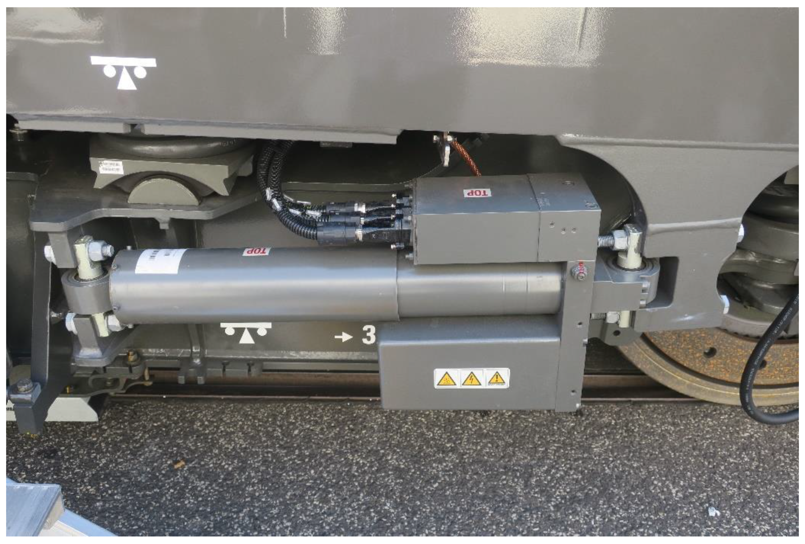
Figure 2.
Graphical representation of the simulation model.
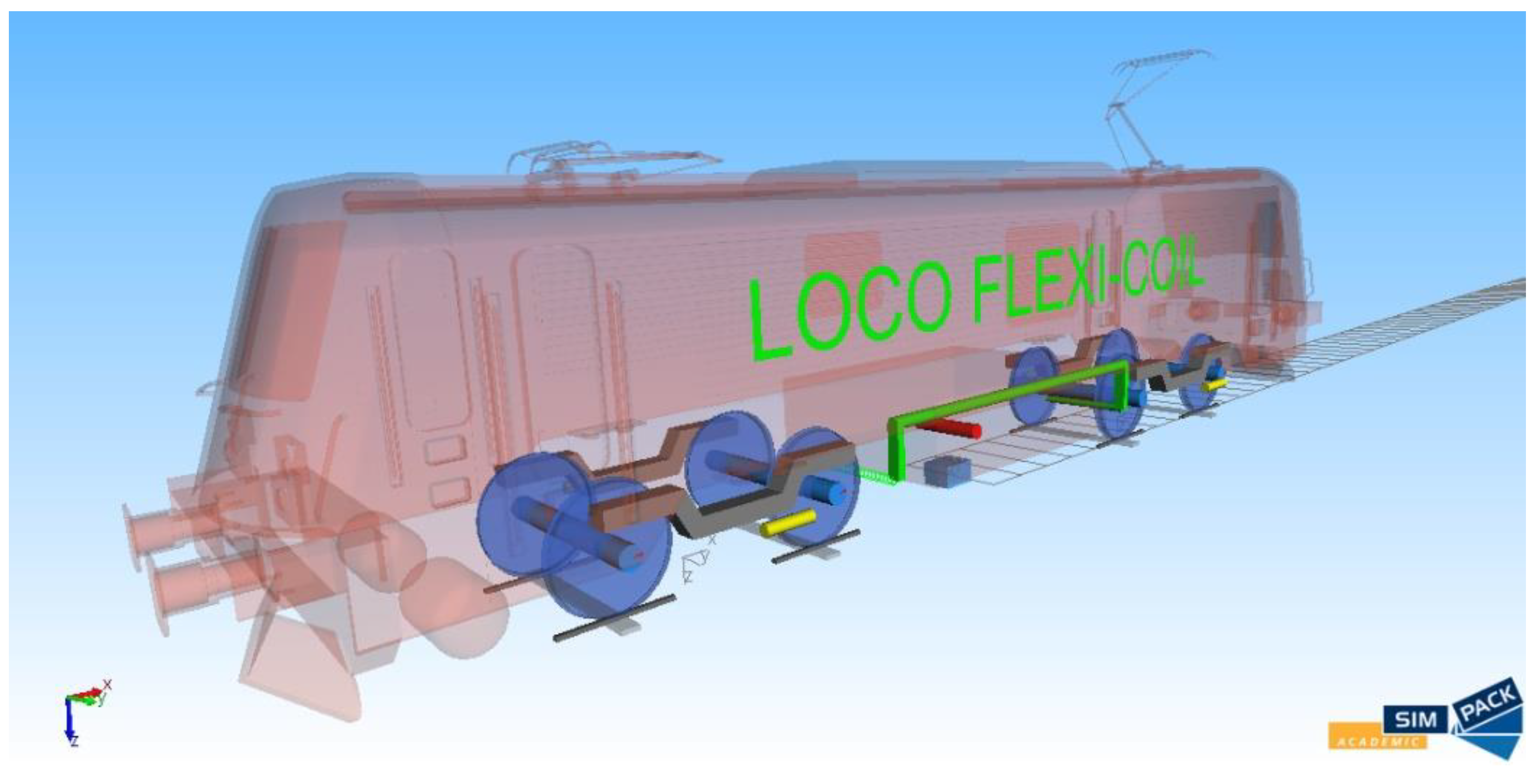
Figure 4.
Quasistatic guiding force acting on outer wheel of the 1st wheelset in curve with radius R = 150 m for various vehicle configurations.
Figure 4.
Quasistatic guiding force acting on outer wheel of the 1st wheelset in curve with radius R = 150 m for various vehicle configurations.

Figure 5.
Scaled roller rig of the Czech Technical University.

Figure 6.
Planar view of a vehicle in the constant curvature track.
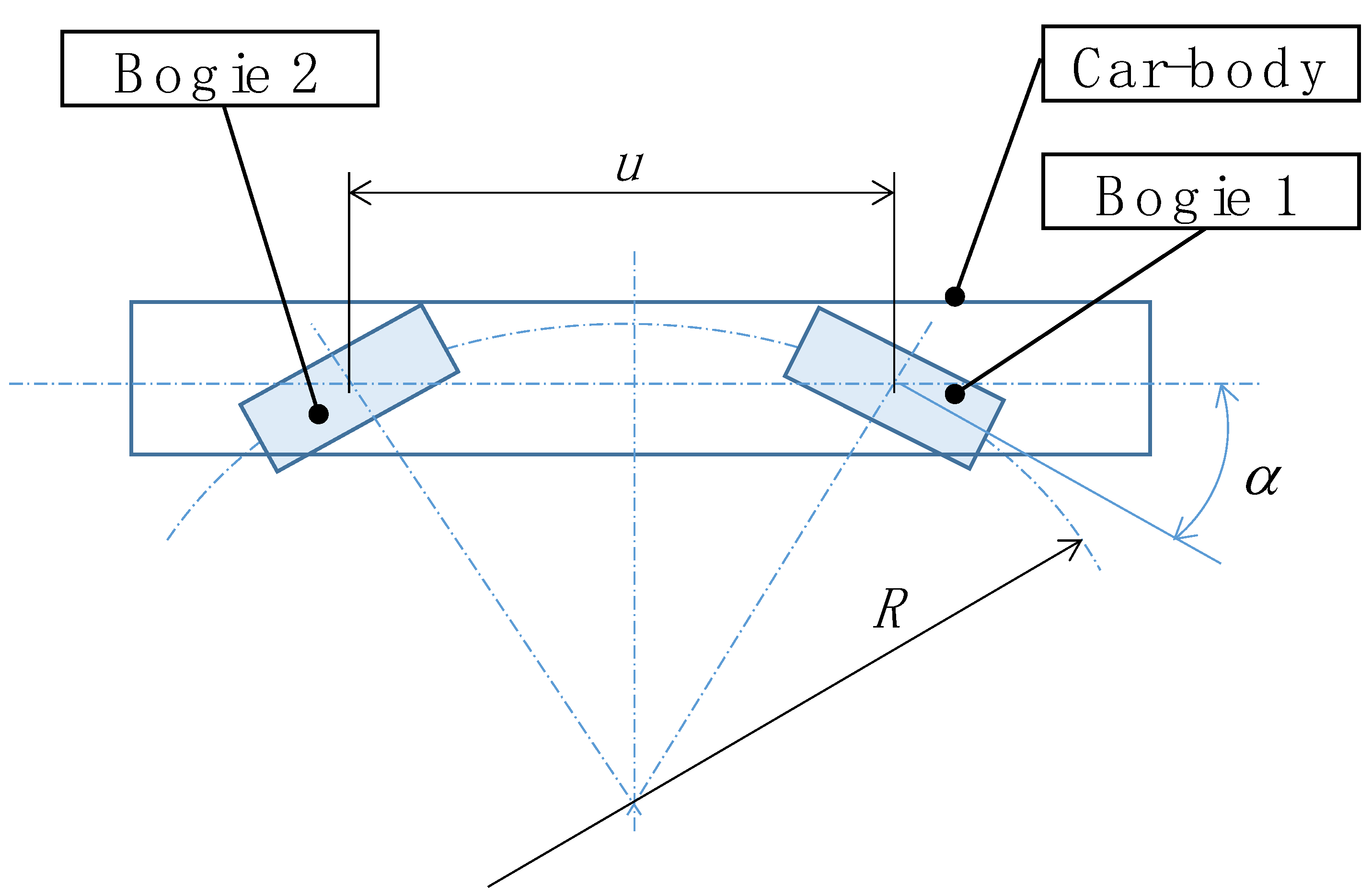
Figure 7.
Track curvature estimated by bogie to car body rotation.

Figure 8.
Track curvature estimated by bogie to car body rotation and its derivative.
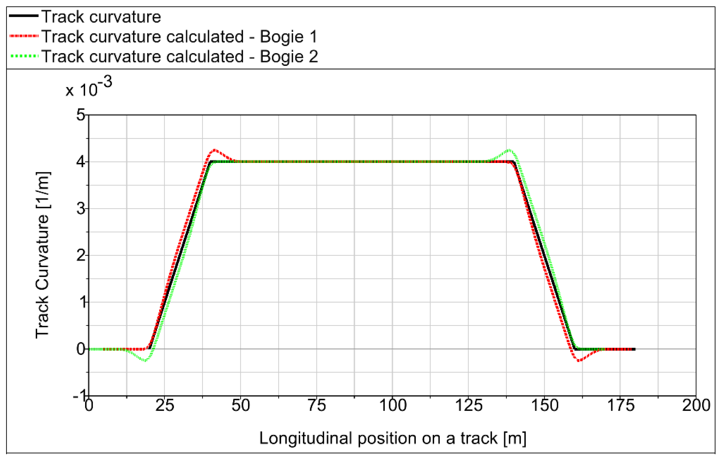
Figure 9.
Comparison of track curvature estimation error.

Figure 10.
Comparison of the nominal value of the track curvature and track curvature calculated by measurement of bogie to car body angle. Bogie 1 (a) and Bogie 2 (b).
Figure 10.
Comparison of the nominal value of the track curvature and track curvature calculated by measurement of bogie to car body angle. Bogie 1 (a) and Bogie 2 (b).

Figure 11.
Test track Letohrad–Lichkov.
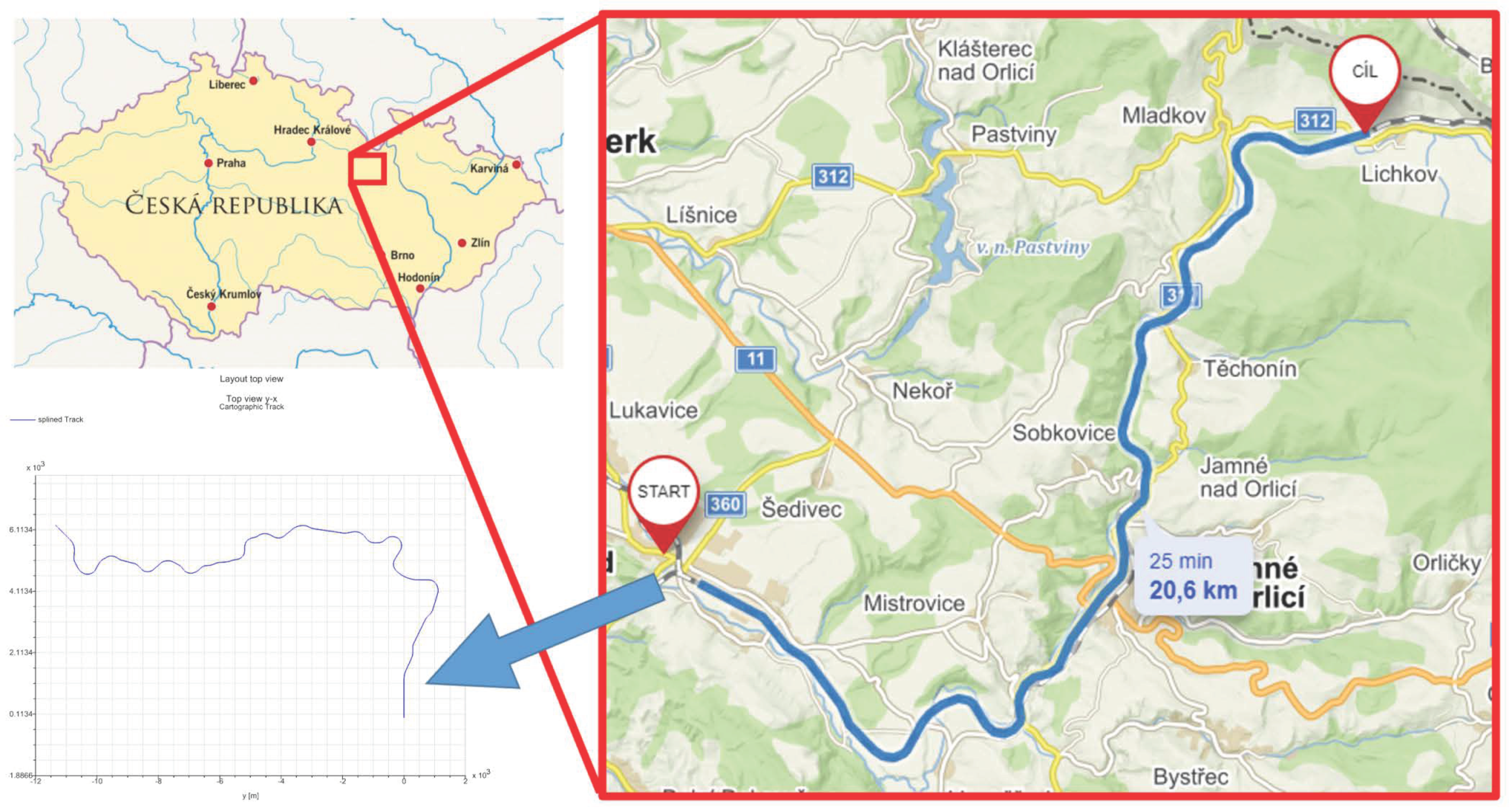
Figure 12.
Simulation of the track Letohrad–Lichkov run for the friction coefficient f = 0.4. Comparison of the nominal value of the track curvature and the track curvature estimated by bogie to car body angle measurement.
Figure 12.
Simulation of the track Letohrad–Lichkov run for the friction coefficient f = 0.4. Comparison of the nominal value of the track curvature and the track curvature estimated by bogie to car body angle measurement.

Figure 13.
Simulation of the track Letohrad–Lichkov run for the friction coefficient f = 0.15. Comparison of the nominal value of the track curvature and the track curvature estimated by bogie to car body angle measurement.
Figure 13.
Simulation of the track Letohrad–Lichkov run for the friction coefficient f = 0.15. Comparison of the nominal value of the track curvature and the track curvature estimated by bogie to car body angle measurement.

Figure 14.
Principle (a) and design solution (b) of the roller rig tilting.

Figure 15.
Strain gauge instrumented roller with wireless transmitter module.
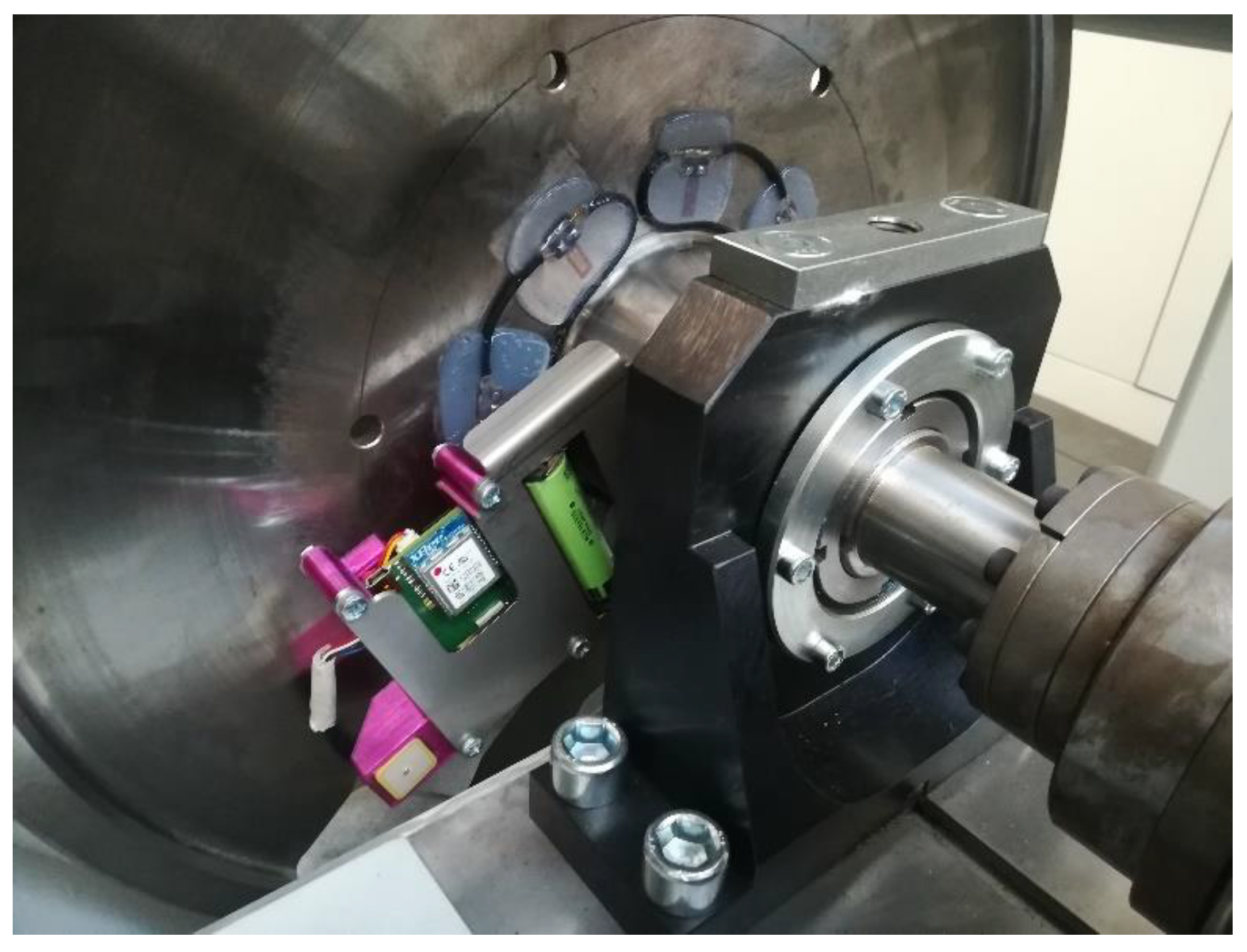
Figure 16.
3D view (a) and assembly drawing (b) of wheelset steering mechanism.
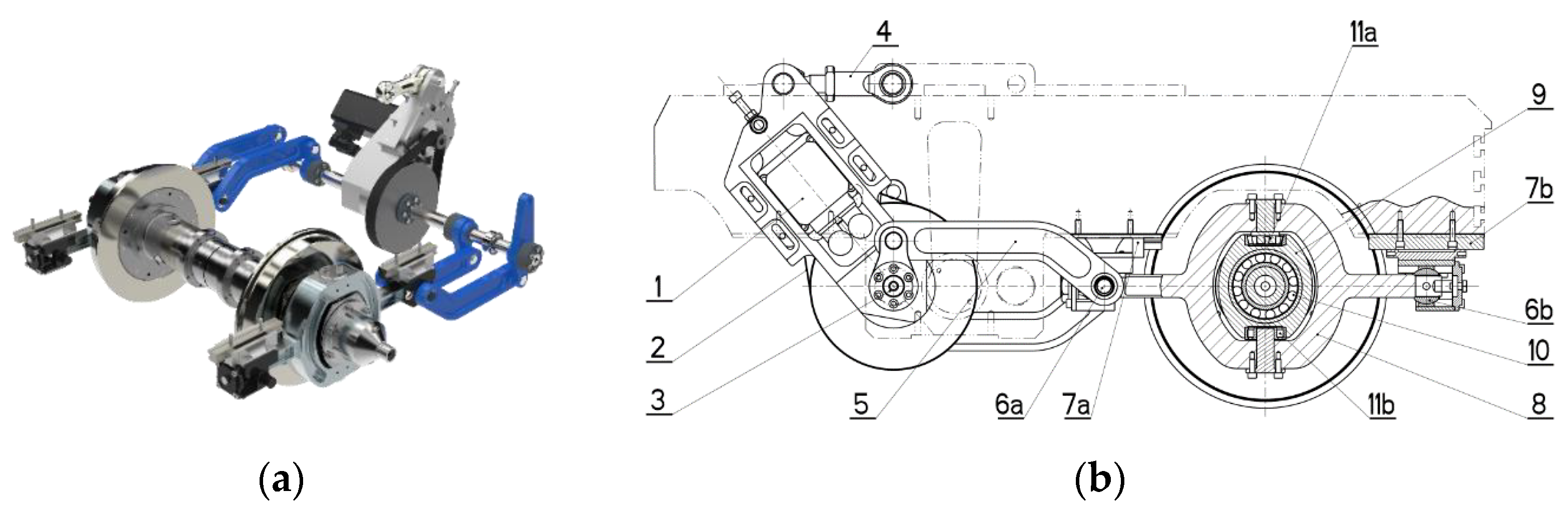
Figure 17.
Instrumented stirrup.

Figure 18.
Measured data—vehicle run in a canted straight track.
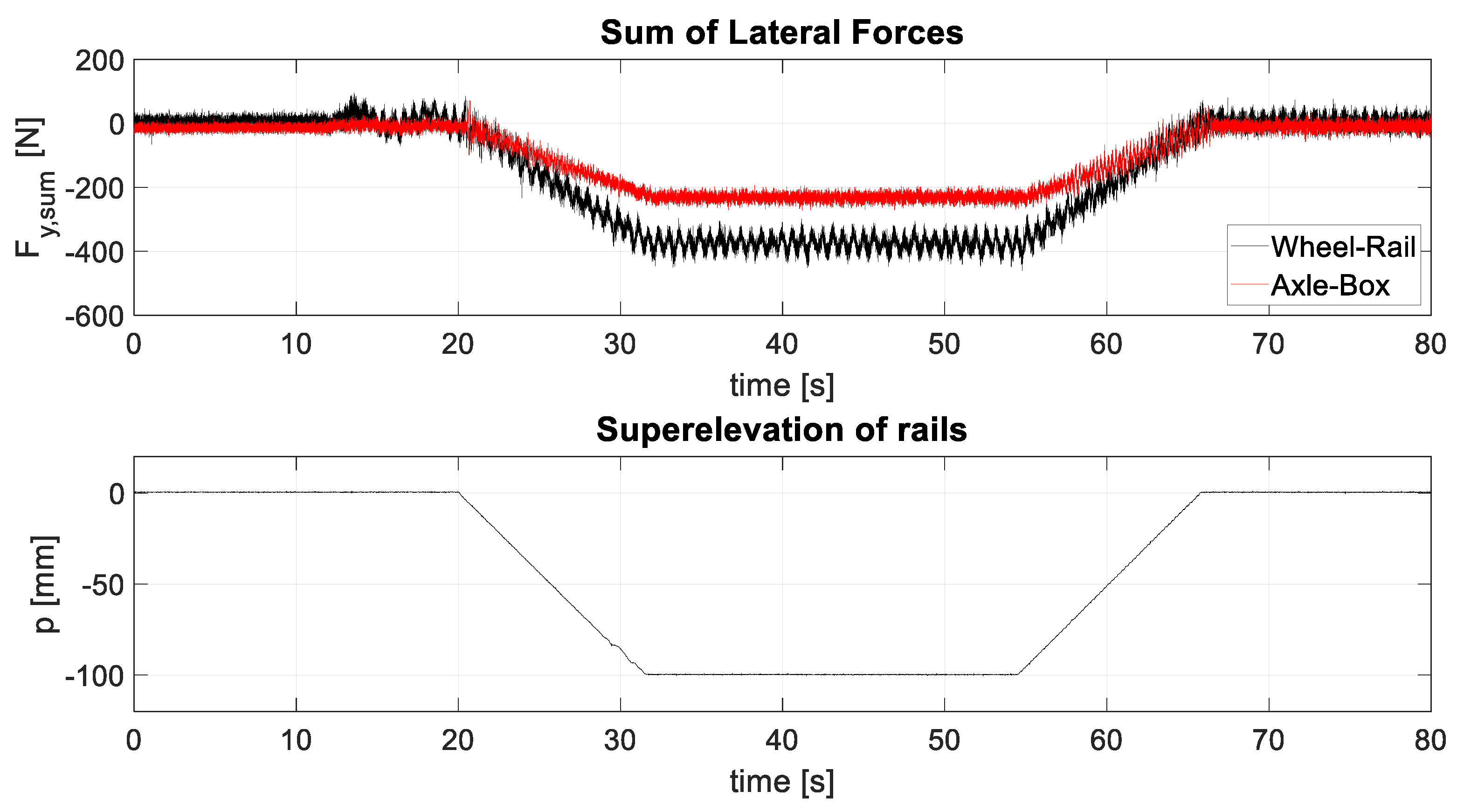
Figure 19.
Measured data—active wheelset steering test, R = 300 m.

Figure 20.
Measured data—active wheelset steering test, R = 400 m.

Figure 21.
Measured data—active wheelset steering test, R = 500 m.

Table 1.
Main parameters of the simulation model.
| Parameter | Value | Unit |
|---|---|---|
| Vehicle mass | 90 | t |
| Bogie mass | 16.6 | t |
| Gauge | 1435 | mm |
| Wheel diameter | 1250 | mm |
| Wheelset distance | 2500 | mm |
| Bogie distance | 8700 | mm |
| Stiffness of primary suspension and wheelset guidance per axle box | ||
| longitudinal | 85,000 | N/mm |
| lateral | 3800 | N/mm |
| vertical | 2200 | N/mm |
| Lateral distance of axle boxes | 2000 | mm |
| Stiffness of secondary suspension spring longitudinal | 150 | N/mm |
| lateral | 150 | N/mm |
| vertical | 500 | N/mm |
| Lateral distance of secondary springs | 2740 | N/mm |
| Number of secondary springs per bogie | 4 | - |
Table 2.
Yqst for different vehicle setups.
| Vehicle Setup | STD | YFS | MBC1 | MBC2 | AYD | AWS |
|---|---|---|---|---|---|---|
| Yqst (kN) | 67.9 | 17.0 | 52.3 | 60.8 | 50.4 | 21.6 |
| Yqst reduction (%) | 0.0% | 75.0% | 23.0% | 10.5% | 25.7% | 68.1% |
Table 3.
Track curvature estimation error for extreme positions of wheelsets.
| Bogie 1 | Bogie 2 | |||||||
|---|---|---|---|---|---|---|---|---|
| R | ρ | α | αmax | ρmax | ∆ρ | αmin | ρmin | ∆ρ |
| [m] | [1/m] | [rad] | [rad] | [1/m] | [%] | [rad] | [1/m] | [%] |
| 250 | 0.0040 | 0.0174 | 0.0226 | 0.0052 | 29.9 | 0.0122 | 0.0028 | −29.9 |
| 300 | 0.0033 | 0.0145 | 0.0197 | 0.0045 | 35.9 | 0.0093 | 0.0021 | −35.9 |
| 400 | 0.0025 | 0.0109 | 0.0161 | 0.0037 | 47.8 | 0.0057 | 0.0013 | −47.8 |
| 500 | 0.0020 | 0.0087 | 0.0139 | 0.0032 | 59.8 | 0.0035 | 0.0008 | −59.8 |
| 600 | 0.0017 | 0.0073 | 0.0125 | 0.0029 | 71.7 | 0.0021 | 0.0005 | −71.7 |
| 800 | 0.0013 | 0.0054 | 0.0106 | 0.0024 | 95.6 | 0.0002 | 0.0001 | −95.6 |
| 1000 | 0.0010 | 0.0044 | 0.0096 | 0.0022 | 119.5 | −0.0009 | −0.0002 | −119.5 |
Table 4.
Simulations parameters.
| Manoeuvre № | R | p | v | an |
|---|---|---|---|---|
| [-] | [m] | [m] | [km/h] | [m/s−2] |
| 1 | 250 | 150 | 56.52 | 0 |
| 2 | 300 | 150 | 61.91 | 0 |
| 3 | 500 | 150 | 79.93 | 0 |
| 4 | 600 | 150 | 87.56 | 0 |
| 5 | 800 | 150 | 101.11 | 0 |
| 6 | 1000 | 150 | 113.04 | 0 |
| 7 | 250 | 150 | 80.22 | 1 |
| 8 | 300 | 150 | 87.87 | 1 |
| 9 | 500 | 150 | 113.44 | 1 |
| 10 | 600 | 150 | 124.27 | 1 |
| 11 | 800 | 150 | 143.49 | 1 |
| 12 | 1000 | 150 | 160.43 | 1 |
| 13 | 250 | 150 | 32.99 | −0.65 |
| 14 | 300 | 150 | 36.14 | −0.65 |
| 15 | 500 | 150 | 46.66 | −0.65 |
| 16 | 600 | 150 | 51.11 | −0.65 |
| 17 | 800 | 150 | 59.02 | −0.65 |
| 18 | 1000 | 150 | 65.98 | −0.65 |
Table 5.
Calculated track curvature using Formula (5).
| Bogie 1 | Bogie 2 | ||||||
|---|---|---|---|---|---|---|---|
| № | |||||||
| [-] | [m] | [m/s−2] | [1/m] | [1/m] | [%] | [1/m] | [%] |
| 1 | 250 | 0 | 4.00 × 10⁻³ | 3.99 × 10⁻³ | −0.2 | 4.04 × 10⁻³ | 1.1 |
| 2 | 300 | 0 | 3.33 × 10⁻³ | 3.31 × 10⁻³ | −0.8 | 3.40 × 10⁻³ | 1.9 |
| 3 | 500 | 0 | 2.00 × 10⁻³ | 1.93 × 10⁻³ | −3.5 | 2.07 × 10⁻³ | 3.4 |
| 4 | 600 | 0 | 1.67 × 10⁻³ | 1.61 × 10⁻³ | −3.6 | 1.71 × 10⁻³ | 2.9 |
| 5 | 800 | 0 | 1.25 × 10⁻³ | 1.18 × 10⁻³ | −5.5 | 1.29 × 10⁻³ | 2.8 |
| 6 | 1000 | 0 | 1.00 × 10⁻³ | 9.26 × 10⁻³ | −7.4 | 1.03 × 10⁻³ | 2.8 |
| 7 | 250 | 1 | 4.00 × 10⁻³ | 4.26 × 10⁻³ | 6.6 | 3.86 × 10⁻³ | −3.6 |
| 8 | 300 | 1 | 3.33 × 10⁻³ | 3.57 × 10⁻³ | 7.1 | 3.22 × 10⁻³ | −3.4 |
| 9 | 500 | 1 | 2.00 × 10⁻³ | 2.20 × 10⁻³ | 9.9 | 1.91 × 10⁻³ | −4.7 |
| 10 | 600 | 1 | 1.67 × 10⁻³ | 1.89 × 10⁻³ | 13.6 | 1.53 × 10⁻³ | −7.9 |
| 11 | 800 | 1 | 1.25 × 10⁻³ | 1.49 × 10⁻³ | 19.1 | 1.09 × 10⁻³ | −12.8 |
| 12 | 1000 | 1 | 1.00 × 10⁻³ | 1.25 × 10⁻³ | 25.1 | 8.22 × 10⁻³ | −17.8 |
| 13 | 250 | −0.65 | 4.00 × 10⁻³ | 3.76 × 10⁻³ | −6.0 | 4.17 × 10⁻³ | 4.2 |
| 14 | 300 | −0.65 | 3.33 × 10⁻³ | 3.14 × 10⁻³ | −5.8 | 3.51 × 10⁻³ | 5.4 |
| 15 | 500 | −0.65 | 2.00 × 10⁻³ | 1.80 × 10⁻³ | −9.8 | 2.14 × 10⁻³ | 7.2 |
| 16 | 600 | −0.65 | 1.67 × 10⁻³ | 1.46 × 10⁻³ | −12.2 | 1.80 × 10⁻³ | 8.0 |
| 17 | 800 | −0.65 | 1.25 × 10⁻³ | 1.03 × 10⁻³ | −17.3 | 1.37 × 10⁻³ | 9.8 |
| 18 | 1000 | −0.65 | 1.00 × 10⁻³ | 7.74 × 10⁻³ | −22.6 | 1.12 × 10⁻³ | 11.6 |
Table 6.
Calculated track curvature for low friction conditions.
| Bogie 1 | Bogie 2 | ||||||
|---|---|---|---|---|---|---|---|
| № | |||||||
| [-] | [m] | [m/s−2] | [1/m] | [1/m] | [%] | [1/m] | [%] |
| 1 | 250 | 0 | 4.00 × 10⁻³ | 4.04 × 10⁻³ | 0.99 | 3.76 × 10⁻³ | −5.99 |
| 2 | 300 | 0 | 3.33 × 10⁻³ | 3.33 × 10⁻³ | −0.10 | 3.21 × 10⁻³ | −3.60 |
| 3 | 500 | 0 | 2.00 × 10⁻³ | 1.91 × 10⁻³ | −4.53 | 2.01 × 10⁻³ | 0.70 |
| 4 | 600 | 0 | 1.67 × 10⁻³ | 1.57 × 10⁻³ | −5.94 | 1.69 × 10⁻³ | 1.30 |
| 5 | 800 | 0 | 1.25 × 10⁻³ | 1.16 × 10⁻³ | −7.52 | 1.26 × 10⁻³ | 1.05 |
| 6 | 1000 | 0 | 1.00 × 10⁻³ | 9.20 × 10⁻³ | −8.01 | 1.00 × 10⁻³ | 0.04 |
| 7 | 250 | 1 | 4.00 × 10⁻³ | 4.45 × 10⁻³ | 11.20 | 3.41 × 10⁻³ | −14.80 |
| 8 | 300 | 1 | 3.33 × 10⁻³ | 3.72 × 10⁻³ | 11.55 | 2.86 × 10⁻³ | −14.13 |
| 9 | 500 | 1 | 2.00 × 10⁻³ | 2.30 × 10⁻³ | 14.88 | 1.70 × 10⁻³ | −14.90 |
| 10 | 600 | 1 | 1.67 × 10⁻³ | 2.10 × 10⁻³ | 25.72 | 1.36 × 10⁻³ | −18.57 |
| 11 | 800 | 1 | 1.25 × 10⁻³ | 1.57 × 10⁻³ | 25.22 | 9.68 × 10⁻³ | −22.54 |
| 12 | 1000 | 1 | 1.00 × 10⁻³ | 1.25 × 10⁻³ | 24.73 | 7.67 × 10⁻³ | −23.25 |
| 13 | 250 | −0.65 | 4.00 × 10⁻³ | 3.80 × 10⁻³ | −4.99 | 3.95 × 10⁻³ | −1.33 |
| 14 | 300 | −0.65 | 3.33 × 10⁻³ | 3.09 × 10⁻³ | −7.39 | 3.38 × 10⁻³ | 1.34 |
| 15 | 500 | −0.65 | 2.00 × 10⁻³ | 1.73 × 10⁻³ | −13.47 | 2.15 × 10⁻³ | 7.44 |
| 16 | 600 | −0.65 | 1.67 × 10⁻³ | 1.39 × 10⁻³ | −16.44 | 1.82 × 10⁻³ | 9.09 |
| 17 | 800 | −0.65 | 1.25 × 10⁻³ | 9.68 × 10⁻³ | −22.57 | 1.39 × 10⁻³ | 11.51 |
| 18 | 1000 | −0.65 | 1.00 × 10⁻³ | 7.16 × 10⁻³ | −28.37 | 1.14 × 10⁻³ | 13.78 |
Publisher’s Note: MDPI stays neutral with regard to jurisdictional claims in published maps and institutional affiliations. |
© 2021 by the authors. Licensee MDPI, Basel, Switzerland. This article is an open access article distributed under the terms and conditions of the Creative Commons Attribution (CC BY) license (https://creativecommons.org/licenses/by/4.0/).
Share and Cite
MDPI and ACS Style
Kalivoda, J.; Bauer, P.; Novák, Z. Assessment of Active Wheelset Steering System Using Computer Simulations and Roller Rig Tests. Appl. Sci. 2021, 11, 11727. https://doi.org/10.3390/app112411727
AMA Style
Kalivoda J, Bauer P, Novák Z. Assessment of Active Wheelset Steering System Using Computer Simulations and Roller Rig Tests. Applied Sciences. 2021; 11(24):11727. https://doi.org/10.3390/app112411727
Chicago/Turabian StyleKalivoda, Jan, Petr Bauer, and Zdeněk Novák. 2021. "Assessment of Active Wheelset Steering System Using Computer Simulations and Roller Rig Tests" Applied Sciences 11, no. 24: 11727. https://doi.org/10.3390/app112411727
Note that from the first issue of 2016, this journal uses article numbers instead of page numbers. See further details here.