Article

A Graphene-Assembled Film Based MIMO Antenna Array with High Isolation for 5G Wireless Communication

1
Hubei Engineering Research Center of RF-Microwave Technology and Application, Wuhan University of Technology, Wuhan 430070, China
2
National Graphene Institute, The University of Manchester, Oxford Rd, Manchester M13 9PL, UK
3
Department of Electroceramics, Instituto de Cerámica y Vidrio CSIC, Kelsen 5, 28049 Madrid, Spain
4
Chongqing 2D Materials Institute, Liangjiang New Area, Chongqing 400714, China
*
Authors to whom correspondence should be addressed.
Appl. Sci. 2021, 11(5), 2382; https://doi.org/10.3390/app11052382
Submission received: 9 February 2021 / Revised: 3 March 2021 / Accepted: 3 March 2021 / Published: 8 March 2021
(This article belongs to the Special Issue Advances of Graphene-Based Nanoplatforms)

Abstract

:
With the development of 5G, Internet of Things, and smart home technologies, miniaturized and compact multi-antenna systems and multiple-input multiple-output (MIMO) antenna arrays have attracted increasing attention. Reducing the coupling between antenna elements is essential to improving the performance of such MIMO antenna system. In this work, we proposed a graphene-assembled, as an alternative material rather than metal, film-based MIMO antenna array with high isolation for 5G application. The isolation of the antenna element is improved by a graphene assembly film (GAF) frequency selective surface and isolation strip. It is shown that the GAF antenna element operated at 3.5 GHz has the realized gain of 2.87 dBi. The addition of the decoupling structure improves the isolation of the MIMO antenna array to more than 10 dB and corrects the antenna radiation pattern and operating frequency. The isolation between antenna elements with an interval of 0.4λ is above 25 dB. All experimental results show that the GAF antenna and decoupling structure are efficient devices for 5G mobile communication.

Graphical Abstract

1. Introduction

In recent years, due to the rapid development of modern wireless communication systems [1,2] and radar technology [3], multi-antenna systems and multiple-input multiple-output (MIMO) antenna arrays have attracted much attention. At the same time, with the requirements of emerging technologies such as 5G (mobile terminals and base stations), the Internet of Things (IoT), and unmanned driving, the trend of miniaturization and integration of microwave systems has also made the physical distance between antennas smaller and smaller. Therefore, for a MIMO antenna system, decoupling between antennas to improve isolation is essential to promote the overall system performance [4]. The coupling of the MIMO antenna system can be expressed by the transmission coefficient between antenna elements, which is essentially the mutual interference of the spatial electric field or surface waves between the antennas. The coupling between antennas is usually reduced by the main polarization configuration and path cancellation. The main polarization configuration method uses the spatial electric field distribution of the antenna, that is, the adjacent antenna adopts different polarization methods to achieve high isolation, such as directional antennas [5,6] and dipole antennas [7]. Path cancellation technology can add a coupling structure to introduce a new coupling path to cancel the original coupling [8,9]. The frequency selective surface (FSS) is a commonly used technique in the path cancellation method. FSS is a periodic structure with the same two-dimensional array elements arranged on a dielectric substrate [10]. As a spatial filter, FSS can pass or block electromagnetic waves in a specific frequency range in free space. Therefore, it is possible to design a compact multi-antenna system (such as a multiple-input multiple-output (MIMO) system) that works in different frequency bands at the same time by using the frequency selection characteristics of FSS. Moreover, FSS is also widely used in the decoupling of multi-antenna systems to obtain better system performance in a compact antenna configuration [11,12,13,14]. In the context of the explosive growth of 5G electronic devices, more properties such as light weight, high thermal conduction, low cost, and easy e-waste disposal are required. Although traditional metals that are applied in current electronic devices can bring good electronic properties, their characteristics of high specific gravity, strong rigidity, and easy oxidation, as well as the significant chemical pollution caused by the preparation process and the process of fabricating electronic devices, are not desirable [15,16,17]. Thus, the development of metal alternative materials has attracted much research attention.
Graphene, as an outstanding carbon-based material, has excellent electrical, mechanical, thermal, and optical properties [18,19]. Compared with traditional metal materials, graphene has high chemical stability and environmental affinity [20]. In the potential applications of future wireless communication systems, graphene is very suitable to being an alternative material rather than metal, such as antennas, attenuator [21,22,23,24,25]. However, single-layer or few-layer graphene sheets need to be deposited on substrate and thus challenging to be uniformly prepared in large sizes. In addition, the post-processing of micro-graphene to obtain a patterned shape requires sophisticated equipment. More importantly, the surface resistance of micro-graphene in the microwave frequency band is as high as hundreds of ohms, which will seriously damage the efficiency of electronic devices [26,27]. The macroscopic graphene assembly film (GAF) formed by stacking graphene nanosheets is another approach of applying graphene material. GAF has inherited the excellent properties of carbon-based materials and can be prepared industrially, which has received extensive research attention [28,29,30]. In this respect, we have investigated a high-conductivity GAF and used it as an antenna design in our recent work. In addition, we designed a miniaturized GAF FSS, which has the advantages of lightweight, low profile and good flexibility [31,32,33,34].
In this work, we designed a 5G MIMO antenna array based on GAF and employed GAF FSS and isolation strips to improve the isolation between MIMO antenna elements. The GAF has a high conductivity of 1.1 × 10⁶ S/m and low density of 1.48 g/cm3. Moreover, the thermal conductive ability of GAF is much higher than copper foil. The GAF MIMO antenna array consists of four identical antenna elements arranged horizontally with an interval of 0.4λ. The GAF antenna element working at 3.5 GHz has a good radiation capability with a maximum realized gain of 2.87 dBi. After deploying the decoupling structure of GAF FSS and isolation strips, the isolation between MIMO antenna elements is increased by more than 10 dB, and the reflection coefficient and radiation pattern are corrected. All results prove that GAF and its electronics are in line with the development requirements of 5G wireless communication.

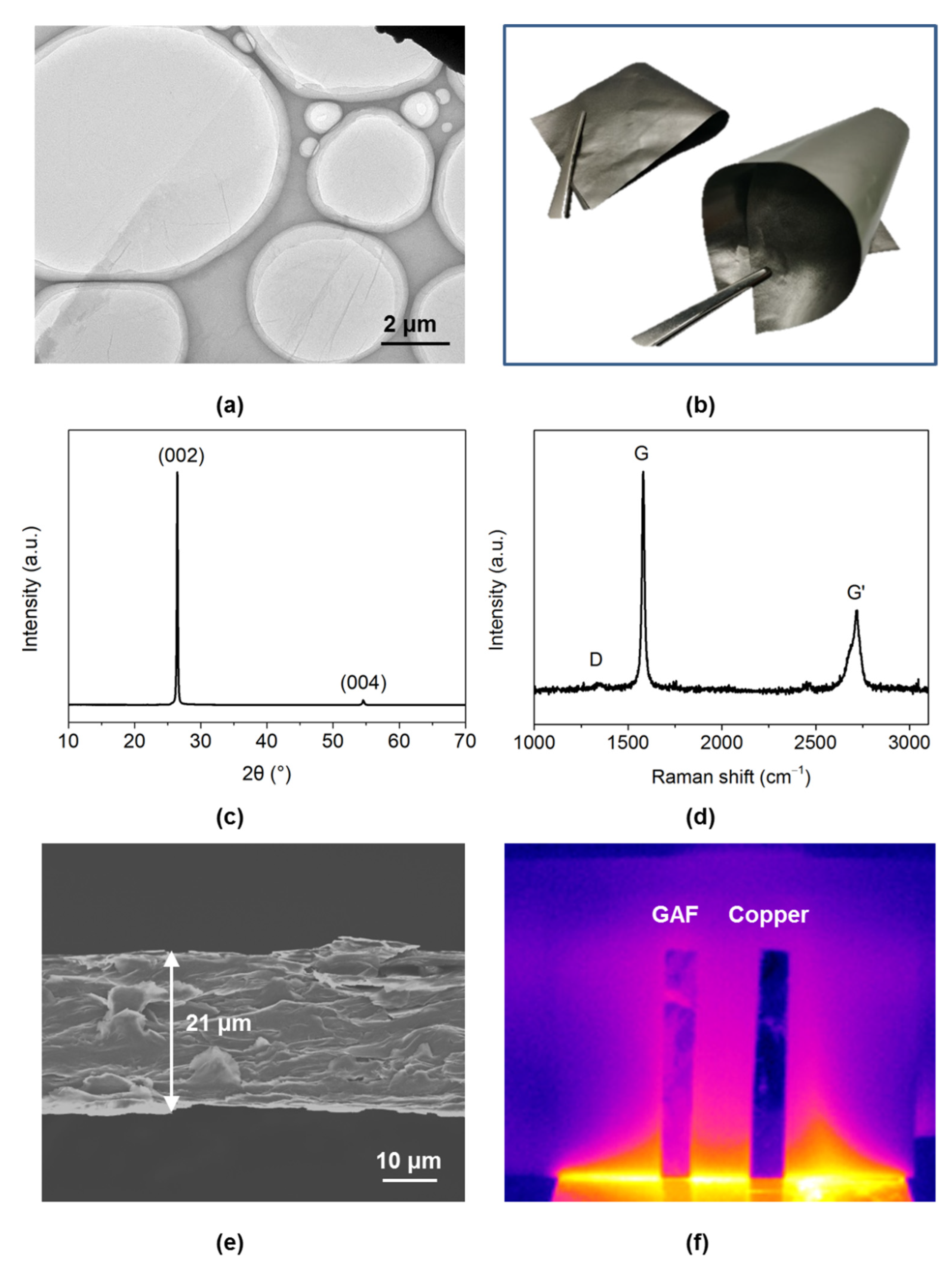
2. Preparation and Characterization of GAF

The GAF is fabricated by a high temperature annealing graphene oxide (GO) film method. Firstly, the GO suspension was diluted to 15 mg/mL by ultrapure water. Then, the GO suspension was coated on the polyethylene terephthalate (PET) substrate and evaporated at room temperature to prepare GO assembled film. The thickness and area of GO-assembled film are controllable. After that, the GO assembled film was annealed to carbonization at 1300 °C for 2 h and graphitization at 2850 °C for 1 h in argon gas (Ar) atmosphere. Finally, the GAF obtained after rolling compression with the pressure of 200 MPa. Figure 1a shows the transmission electron microscope (TEM) image of GO sheet. Figure 1b is the digital photo of GAF showing that GAF has good flexibility and does not need any substrate. GAF has comparable electrical conductivity to metals measured by four probe method (1.1 × 10⁶ S/m) [32], which lays the foundation for the design of high-performance antennas and other electronics. Furthermore, the density of GAF is only 1.48 g/cm3. Figure 1c illustrates the X-ray diffraction (XRD) pattern of GAF. The extremely graphitic peak (002) located at 26.5° indicates that the GAF has a regular stacking of graphene sheets and the interlayer spacing of 0.34 nm. Moreover, the characteristic peak (004) proves the GAF has high degree of graphitization. Figure 1d shows that the weak D peak and strong G peak in the Raman spectrum demonstrated the GAF has few defects. All the characterization results elucidate that GAF has high conductivity. The cross-section image in Figure 1e shows that the GAF with a thickness of 21 μm is composed of regular stacks of graphene nanosheets.
Additionally, compared with copper, the temperature of GAF increases rapidly under the same heating condition, as shown in Figure 1f. GAF has better thermal conductivity, which is more suitable for the design of miniaturization and high integration electronics.

3. The Design of GAF MIMO Antenna Array

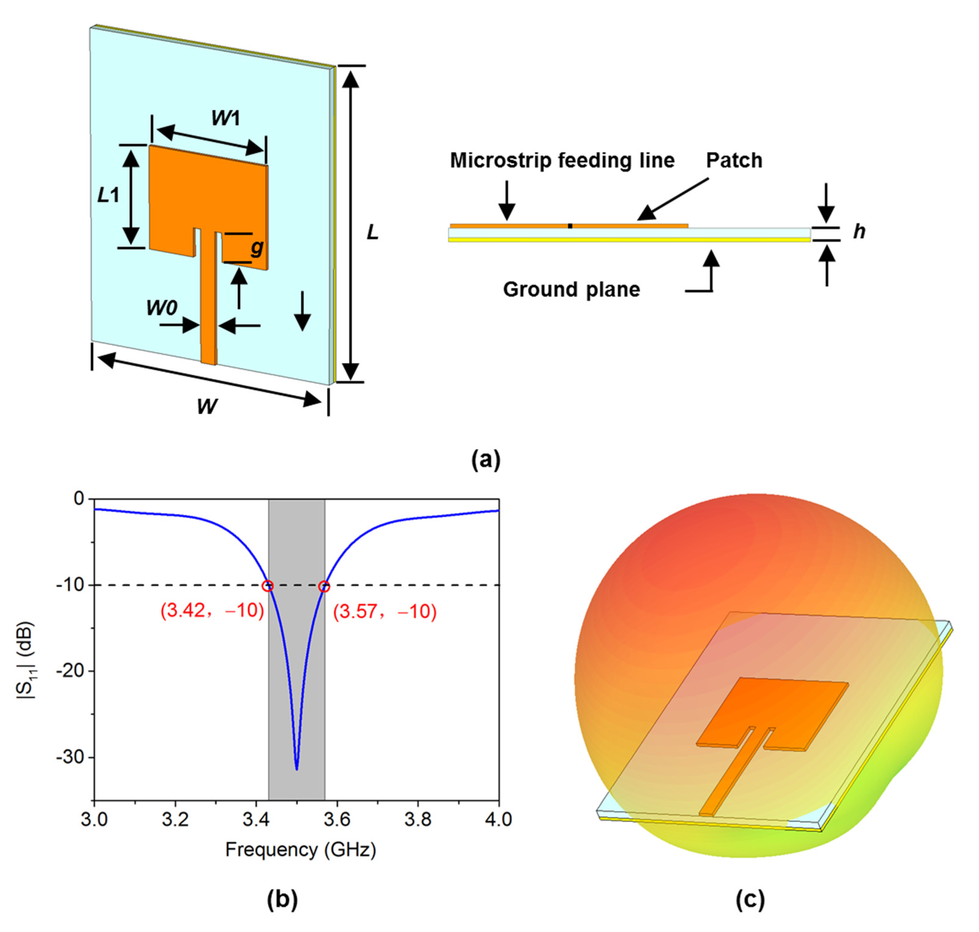
3.1. The Structure and Dimension of GAF Antenna Element

The proposed GAF MIMO antenna array is microstrip antenna with the advantages of low profile, miniaturization and easy integration. Figure 2a is the schematic diagram of the GAF antenna element geometry structure. The GAF antenna is designed on FR-4 PCB substrate with relative permittivity of 4.3 and dielectric loss tangent of 0.03. The thickness (h) of PCB is 1.6 mm. Unlike traditional antennas, the radiator material of the antenna is highly conductive GAF. The length and width of the dielectric substrate and the radiator are L = 60 mm, W = 50 mm, L1 = 19.8 mm, W1 = 24.5 mm, respectively. A 50 ohms microstrip feed line with width of 2.98 mm is utilized to feed for the GAF antenna. The antenna patch and microstrip line can achieve impedance matching by changing the insertion depth (g). The optimized g is 5.65 mm.
The GAF antenna element model is simulated in CST electromagnetic simulation software to analyze the performance. Figure 2b depicts the simulated return loss of GAF antenna element. The GAF antenna element operates at 3.5 GHz, which is the Sub-6 GHz frequency band of 5G mobile communications. The −10 dB impedance bandwidth is 3.42–3.57 GHz, which indicates that above 90% energy in this frequency band is radiated to free space via the antenna. The 3D radiation pattern of GAF antenna element is shown in Figure 2c. The simulated realized gain is 2.87 dBi.

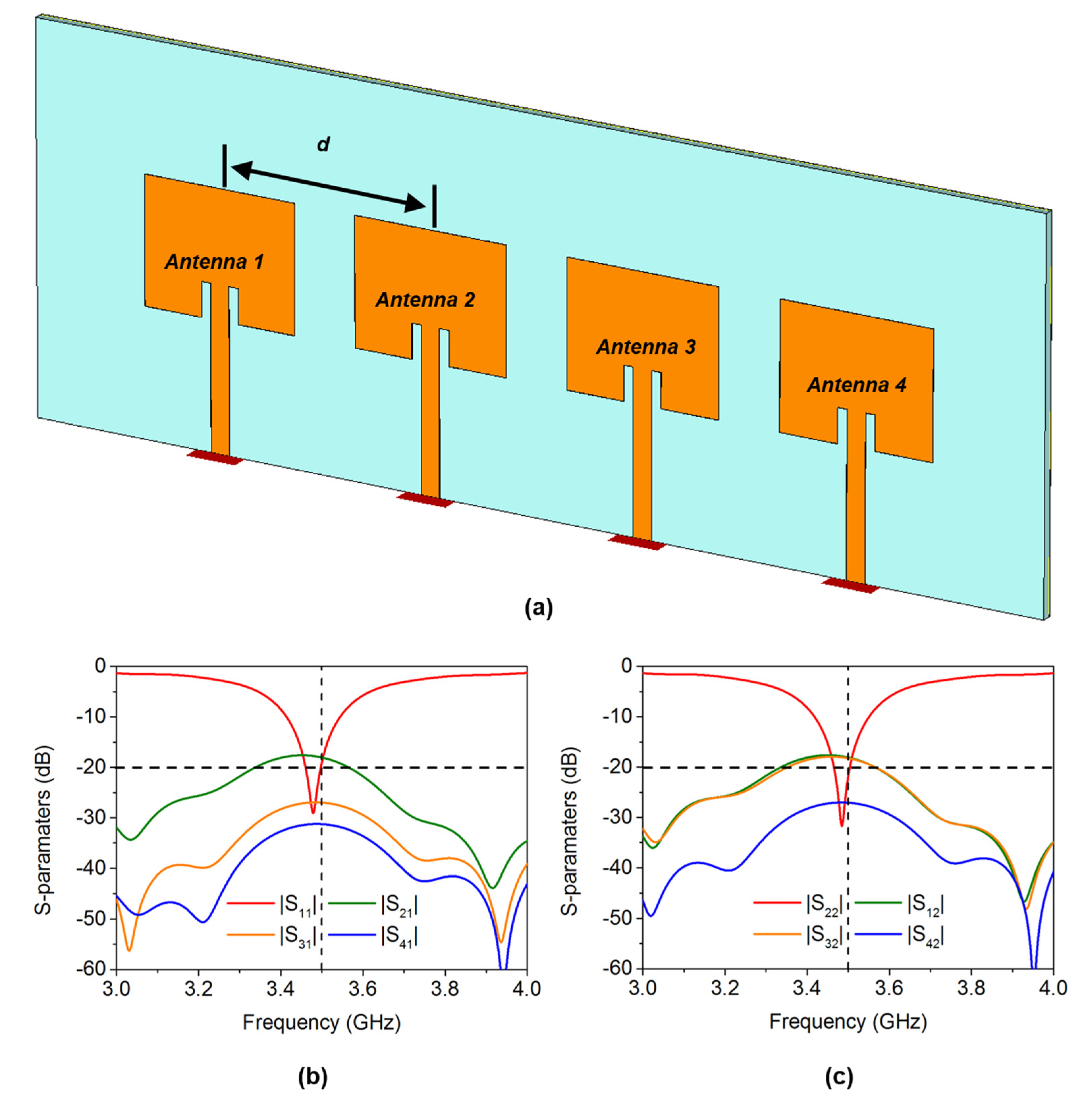
3.2. The Configuration of GAF MIMO Antenna Array

The proposed GAF MIMO antenna has four independent and identical antenna elements. The distance (d) between the four antennas is 0.4λ (λ is the free space wavelength of 3.5 GHz), and the configuration is shown in Figure 3a.
Due to symmetry, the performances of Antenna 1 and Antenna 2 can represent the entire GAF MIMO antenna array. The simulated S-parameters of Antenna 1 and Antenna 2 are depicted in Figure 3b,c. The operating frequency of the MIMO antenna array is slightly deflected due to the influence of mutual coupling. Moreover, the isolation of adjacent antennas is less than 20 dB at 3.5 GHz (|S21|, |S12|, |S32| > −20 dB), which will seriously affect the antenna’s radiation pattern and efficiency.
As analyzed above, the mutual coupling between antennas will affect the radiation pattern. The four antennas are arranged along the H-plane direction, so the H-plane radiation pattern has a greater impact but has no effect on the E-plane radiation pattern, which is proved in Figure 4. The E-plane radiation patterns of Antenna 1 and Antenna 2 are not deflected, while the H-plane patterns deviated by 9° and 26°, respectively.

4. Reduce the Coupling of GAF MIMO Antenna Array

We propose two ways to reduce the coupling between MIMO antenna elements. One way is to use GAF FSS to isolate spatial electromagnetic waves, and the other is to set two GAF isolation strips (ISs) between antenna elements to suppress the influence of surface electromagnetic waves. The isolation of the antenna elements can be effectively improved by adjusting the width and the spacing of the two GAF ISs. The optimized width of the GAF IS is 0.5 mm, and the length is consistent with the length of the dielectric substrate. The gap between the two GAFS is 3 mm. In addition, the GAF FSS is placed in the middle of two ISs. The substrate of GAF FSS is PET film with a thickness of 0.06 mm, dielectric constant of 3.5 and loss tangent of 0.003. The dimension of the GAF FSS element is 16 mm × 16 mm. The width and total length are 0.5 mm and 39.8 mm, respectively, as shown in Figure 5. In practice, FSS can be integrated into the device by means of a card slot. Additionally, for high-power devices, the hollow structure is more benefiting to heat dissipate management.
Figure 6 shows the isolation between Antenna 1/Antenna 2 and adjacent antenna elements in the four cases of no decoupling structure, only GAF IS, only FAF FSS, and both GAF IS and FSS. It can be clearly seen from the results that both GAF IS and FSS have significant benefits in improving isolation, and both can be increased to more than 20 dB. The dual decoupling structure of GAF IS and FSS is the superposition of the effects when the two structures exist separately.
As shown in Figure 7a,b, the isolation between GAF MIMO antenna elements is significantly improved, after adding an isolation structure of GAF FSSs and isolation strips. When Antenna 1 is used as a radiation source, the transmission coefficients between Antenna 1 and each antenna are |S21| = −28.82 dB, |S31| = −44.86 dB, |S41| = −51.83 dB. When Antenna 2 is used as a radiation source, the isolation from each antenna is |S12| = −28.57 dB, |S32| = −25.41 dB, |S42| = −43.95 dB. Compared with the initial GAF MIMO antenna array, the isolation is improved by more than 10 dB.
The surface current can deeply analyze the working mode of the antenna. Figure 7c–f show the surface current of the entire MIMO antenna array when Antenna 1 and Antenna 2 are used as radiation sources, respectively. When Antenna 1 is used as a radiation source and no decoupling structure is added, there are strongly induced surface currents on Antenna 2, Antenna 3 and Antenna 4, which are caused by the coupling field, as shown in Figure 7c. On the other hand, when GAF FSS and IS are added, there is almost no induced current on the non-radiating antenna, which proves that the decoupling structure suppresses the coupling effect, as shown in Figure 7d. Analogous to the Antenna 2 as the radiation source, the decoupling structure also suppresses the coupling between the antenna elements, as shown in Figure 7e,f.
Compared with the initial MIMO antenna array, the radiation patterns of the GAF MIMO antenna array with the decoupling structure is modified to normal phase radiation, as shown in Figure 8.

5. Measurement of GAF MIMO Antenna Array

5.1. Measurement of GAF Antenna Element

The GAF antenna, FSS and isolation strip are fabricated by laser engraving method with the accuracy of 25 μm. The illustration of Figure 9a shows the digital photo of GAF antenna element. GAF is as the radiator. The performances of GAF antenna element are measured. Figure 9a depicts the reflection coefficient and gain of the GAF antenna element measured by vector network analyzer (Keysight N5247A PNA) in microwave anechoic chamber. In the 3.41–3.58 GHz frequency band, |S11| is lower than −10 dB and the gain is greater than 2 dBi, which is consistent with the simulation results. The radiation patterns at 3.5 GHz are displayed in Figure 8b. The GAF antenna element is used as the receiving antenna, and the standard gain horn antenna is used as the transmitting antenna. Both the transmitting antenna and the receiving antenna are placed in a microwave anechoic chamber and connected with the vector network analyzer. As shown in Figure 9b, the maximum radiation directions of the E-plane and H-plane of the GAF antenna element are both in the normal phase.

5.2. Measurement of GAF MIMO Antenna Array

The proposed GAF MIMO antenna array with the decoupling structure of GAF FSS and isolation strip is shown in Figure 10a. Figure 10b,c show the measured reflection coefficients of Antenna 1 and Antenna 2, respectively.
Compared with the initial antenna, the operating frequency of the GAF MIMO antenna array with the decoupling structure has been corrected and returned to the initial designed of 3.5 GHz.
Furthermore, the transmission coefficients of Antenna 1 and non-radiation antenna are measured. The decoupling structure obviously suppresses the coupling between MIMO antenna elements. The transmission coefficients of MIMO antenna array with GAF FSS and IS have dropped by more than −10 dB compared with that initial MIMO antenna array, and both are below −25 dB, as shown in Figure 11. In addition, the radiation patterns of GAF MIMO antenna array with and without decoupling structure are measured, as is illustrated in Figure 12. The results are recorded every 10° in microwave anechoic chamber by vector network analyzer. In agreement with the simulated results, the decoupling structure corrected the radiation patterns of the MIMO antenna array. The H-plane radiation patterns of Antenna 1 (Figure 12b) and Antenna 2 (Figure 12d) without decoupling structure are deflected by 20°. On the other hand, the radiation patterns of MIMO antenna array with GAF FSS and IS return to normal phase direction.

6. Conclusions

In conclusion, a lightweight graphene-assembled film with high flexibility is presented. For the first time, we designed a 5G MIMO antenna array based on GAF and employed GAF FSS and isolation strips to improve the isolation between MIMO antenna elements. GAF-based microstrip antenna element working at 3.5 GHz has good radiation ability and high realized gain of 2.87 dBi. GAF FSS and isolation strips can effectively suppress the coupling between MIMO antenna elements and increase the isolation by more than 10 dB. In addition, GAF FSS and isolation strips correct the working frequency and radiation pattern of the MIMO antenna array due to coupling. All results prove that GAF and its electronics are in line with the development requirements of 5G wireless communication and can be a strong candidate as a metal alternative material in next generation wireless communication systems.

Author Contributions

Conceptualization, R.S., X.C. and B.M.; methodology, Z.H., T.L. and D.H.; validation, B.M. and D.H.; writing—original draft preparation, R.S., S.J. and B.M.; review and editing, R.S., D.G.C. and B.M.; funding acquisition, R.S. and D.H.; R.S. and X.C. contributed equally to this work. All authors have read and agreed to the published version of the manuscript.

Funding

This research was funded by the National Natural Science Foundation of China (No. 51701146) and the Fundamental Research Funds for the Central Universities (WUT: 2020-YB-032 and 2020IB005).

Institutional Review Board Statement

Not applicable.

Informed Consent Statement

Not applicable.

Data Availability Statement

Not applicable.

Conflicts of Interest

The authors declare no conflict of interest.

References

  1. Shafi, M.; Molisch, A.F.; Smith, P.J.; Haustein, T.; Zhu, P.; De Silva, P.; Tufvesson, F.; Benjebbour, A.; Wunder, G. 5G: A Tutorial Overview of Standards, Trials, Challenges, Deployment, and Practice. IEEE J. Sel. Areas Commun. 2017, 35, 1201–1221. [Google Scholar] [CrossRef]
  2. Silva, M.M.D.; Guerreiro, J. On the 5G and Beyond. Appl. Sci. 2020, 10, 7091. [Google Scholar] [CrossRef]
  3. Liu, F.; Masouros, C.; Li, A.; Sun, H.; Hanzo, L. MU-MIMO Communications with MIMO Radar: From Co-Existence to Joint Transmission. IEEE Trans. Wirel. Commun. 2018, 17, 2755–2770. [Google Scholar] [CrossRef]
  4. Lu, D.; Wang, L.; Yang, E.; Wang, G. Design of High-Isolation Wideband Dual-Polarized Compact MIMO Antennas With Multiobjective Optimization. IEEE Trans. Antennas Propag. 2018, 66, 1522–1527. [Google Scholar] [CrossRef] [Green Version]
  5. Hu, H.; Chen, F.; Chu, Q. A Compact Directional Slot Antenna and Its Application in MIMO Array. IEEE Trans. Antennas Propag. 2016, 64, 5513–5517. [Google Scholar] [CrossRef]
  6. Anitha, R.; Vinesh, P.V.; Prakash, K.C.; Mohanan, P.; Vasudevan, K. A Compact Quad Element Slotted Ground Wideband Antenna for MIMO Applications. IEEE Trans. Antennas Propag. 2016, 64, 4550–4553. [Google Scholar] [CrossRef]
  7. Wen, L.; Gao, S.; Luo, Q.; Mao, C.; Hu, W.; Yin, Y.; Zhou, Y.; Wang, Q. Compact Dual-Polarized Shared-Dipole Antennas for Base Station Applications. IEEE Trans. Antennas Propag. 2018, 66, 6826–6834. [Google Scholar] [CrossRef] [Green Version]
  8. Makar, G.; Tran, N.; Karacolak, T. A High-Isolation Monopole Array with Ring Hybrid Feeding Structure for In-Band Full-Duplex Systems. IEEE Antenn. Wirel. Propag. Lett. 2017, 16, 356–359. [Google Scholar] [CrossRef]
  9. Sui, J.; Wu, K. Self-Curing Decoupling Technique for Two Inverted-F Antennas with Capacitive Loads. IEEE Trans. Antennas Propag. 2018, 66, 1093–1101. [Google Scholar] [CrossRef]
  10. Anwar, R.; Mao, L.; Ning, H. Frequency Selective Surfaces: A Review. Appl. Sci. 2018, 8, 1689. [Google Scholar] [CrossRef] [Green Version]
  11. Chen, Y.; Zhao, J.; Yang, S. A Novel Stacked Antenna Configuration and its Applications in Dual-Band Shared-Aperture Base Station Antenna Array Designs. IEEE Trans. Antennas Propag. 2019, 67, 7234–7241. [Google Scholar] [CrossRef]
  12. Saleem, R.; Bilal, M.; Chattha, H.T.; Ur Rehman, S.; Mushtaq, A.; Shafique, M.F. An FSS Based Multiband MIMO System Incorporating 3D Antennas for WLAN/WiMAX/5G Cellular and 5G Wi-Fi Applications. IEEE Access 2019, 7, 144732–144740. [Google Scholar] [CrossRef]
  13. Zhu, Y.; Chen, Y.; Yang, S. Decoupling and Low-Profile Design of Dual-Band Dual-Polarized Base Station Antennas Using Frequency-Selective Surface. IEEE Trans. Antennas Propag. 2019, 67, 5272–5281. [Google Scholar] [CrossRef]
  14. Das, G.; Sahu, N.K.; Sharma, A.; Gangwar, R.K.; Sharawi, M.S. FSS-Based Spatially Decoupled Back-to-Back Four-Port MIMO DRA With Multidirectional Pattern Diversity. IEEE Antenn. Wirel. Propag. Lett. 2019, 18, 1552–1556. [Google Scholar] [CrossRef]
  15. Awasthi, A.K.; Li, J.; Koh, L.; Ogunseitan, O.A. Circular economy and electronic waste. Nat. Electron. 2019, 2, 86–89. [Google Scholar] [CrossRef] [Green Version]
  16. Masoudi, M.; Khafagy, M.G.; Conte, A.; El-Amine, A.; Francoise, B.; Nadjahi, C.; Salem, F.E.; Labidi, W.; Sural, A.; Gati, A.; et al. Green Mobile Networks for 5G and Beyond. IEEE Access 2019, 7, 107270–107299. [Google Scholar] [CrossRef]
  17. Awasthi, A.K.; Wang, M.; Awasthi, M.K.; Wang, Z.; Li, J. Environmental pollution and human body burden from improper recycling of e-waste in China: A short-review. Environ. Pollut. 2018, 243, 1310–1316. [Google Scholar] [CrossRef]
  18. Novoselov, K.S.; Geim, A.K.; Morozov, S.V.; Jiang, D.; Zhang, Y.; Dubonos, S.V.; Grigorieva, I.V.; Firsov, A.A. Electric field effect in atomically thin carbon films. Science 2004, 306, 666–669. [Google Scholar] [CrossRef] [PubMed] [Green Version]
  19. Novoselov, K.S.; Geim, A.K.; Morozov, S.V.; Jiang, D.; Katsnelson, M.I.; Grigorieva, I.V.; Dubonos, S.V.; Firsov, A.A. Two-dimensional gas of massless Dirac fermions in graphene. Nature 2005, 438, 197–200. [Google Scholar] [CrossRef]
  20. Xin, G.; Yao, T.; Sun, H.; Scott, S.M.; Shao, D.; Wang, G.; Lian, J. Highly thermally conductive and mechanically strong graphene fibers. Science 2015, 349, 1083–1087. [Google Scholar] [CrossRef] [PubMed] [Green Version]
  21. Esquius-Morote, M.; Gomez-Diaz, J.S.; Perruisseau-Carrier, J. Sinusoidally Modulated Graphene Leaky-Wave Antenna for Electronic Beamscanning at THz. IEEE Trans. Terahertz Sci. Technol. 2014, 4, 116–122. [Google Scholar] [CrossRef] [Green Version]
  22. Cabellos-Aparicio, A.; Llatser, I.; Alarcon, E.; Hsu, A.; Palacios, T. Use of Terahertz Photoconductive Sources to Characterize Tunable Graphene RF Plasmonic Antennas. IEEE Trans. Nanotechnol. 2015, 14, 390–396. [Google Scholar] [CrossRef] [Green Version]
  23. Carrasco, E.; Perruisseau-Carrier, J. Reflectarray Antenna at Terahertz Using Graphene. IEEE Antenn. Wirel. Propag. Lett. 2013, 12, 253–256. [Google Scholar] [CrossRef]
  24. Dragoman, M.; Neculoiu, D.; Bunea, A.; Deligeorgis, G.; Aldrigo, M.; Vasilache, D.; Dinescu, A.; Konstantinidis, G.; Mencarelli, D.; Pierantoni, L.; et al. A tunable microwave slot antenna based on graphene. Appl. Phys. Lett. 2015, 106, 153101. [Google Scholar] [CrossRef] [Green Version]
  25. Bozzi, M.; Pierantoni, L.; Bellucci, S. Applications of Graphene at Microwave Frequencies. Radioengineering 2015, 24, 661–669. [Google Scholar] [CrossRef]
  26. Dashti, M.; Carey, J.D. Graphene Microstrip Patch Ultrawide Band Antennas for THz Communications. Adv. Funct. Mater. 2018, 28, 1705925. [Google Scholar] [CrossRef]
  27. Fan, C.; Wu, B.; Song, R.; Zhao, Y.; Zhang, Y.; He, D. Electromagnetic shielding and multi-beam radiation with high conductivity multilayer graphene film. Carbon 2019, 155, 506–513. [Google Scholar] [CrossRef]
  28. Shen, B.; Zhai, W.; Zheng, W. Ultrathin Flexible Graphene Film: An Excellent Thermal Conducting Material with Efficient EMI Shielding. Adv. Funct. Mater. 2014, 24, 4542–4548. [Google Scholar] [CrossRef]
  29. Xin, G.; Sun, H.; Hu, T.; Fard, H.R.; Sun, X.; Koratkar, N.; Borca-Tasciuc, T.; Lian, J. Large-Area Freestanding Graphene Paper for Superior Thermal Management. Adv. Mater. 2014, 26, 4521–4526. [Google Scholar] [CrossRef] [PubMed]
  30. Feng, S.; Yao, T.; Lu, Y.; Hao, Z.; Lin, S. Quasi-industrially produced large-area microscale graphene flakes assembled film with extremely high thermoelectric power factor. Nano Energy 2019, 58, 63–68. [Google Scholar] [CrossRef]
  31. Song, R.; Zhao, X.; Wang, Z.; Fu, H.; Han, K.; Qian, W.; Wang, S.; Shen, J.; Mao, B.; He, D. Sandwiched Graphene Clad Laminate: A Binder-Free Flexible Printed Circuit Board for 5G Antenna Application. Adv. Eng. Mater. 2020, 22, 2000451. [Google Scholar] [CrossRef]
  32. Song, R.; Wang, Q.; Mao, B.; Wang, Z.; Tang, D.; Zhang, B.; Zhang, J.; Liu, C.; He, D.; Wu, Z.; et al. Flexible graphite films with high conductivity for radio-frequency antennas. Carbon 2018, 130, 164–169. [Google Scholar] [CrossRef]
  33. Song, R.; Wang, Z.; Zu, H.; Chen, Q.; Mao, B.; Wu, Z.P.; He, D. Wideband and low sidelobe graphene antenna array for 5G applications. Sci. Bull. 2020. [Google Scholar] [CrossRef]
  34. Zhang, J.; Song, R.; Zhao, X.; Fang, R.; Zhang, B.; Qian, W.; Zhang, J.; Liu, C.; He, D. Flexible Graphene-Assembled Film-Based Antenna for Wireless Wearable Sensor with Miniaturized Size and High Sensitivity. ACS Omega 2020, 5, 12937–12943. [Google Scholar] [CrossRef]
Figure 1. (a) TEM image of graphene oxide (GO) sheet, (b) digital photo, (c) XRD pattern and (d) Raman spectrum of graphene assembly film (GAF), (e) the cross-section SEM image of GAF, (f) thermal conduction comparison of GAF and copper.
Applsci 11 02382 g001
Figure 2. (a) The schematic diagram of the GAF antenna element geometry structure, (b) the simulated reflection coefficient of GAF antenna element, (c) 3D radiation pattern of GAF antenna element.
Applsci 11 02382 g002
Figure 3. (a) The geometry structure of GAF multiple-input multiple-output (MIMO) antenna, (b,c) the simulated S-parameters of GAF MIMO antenna array. (b) Antenna 1, (c) Antenna 2.
Applsci 11 02382 g003
Figure 4. The simulated radiation patterns of GAF MIMO antenna array. (a,b) The E-plane and H-plane radiation patterns of Antenna 1, respectively, (c,d) The E-plane and H-plane radiation patterns of Antenna 2, respectively.
Applsci 11 02382 g004
Figure 5. The geometry structure of GAF MIMO antenna array with GAF frequency selective surface (FSS) and isolation strips (ISs).
Applsci 11 02382 g005
Figure 6. Isolation comparison with/without GAF IS and FSS. (a) |S21|, (b) |S12|, (c) |S32|.
Applsci 11 02382 g006
Figure 7. (a,b) The simulated S-parameters of GAF MIMO antenna array with GAF FSS and IS. (a) Antenna 1, (b) Antenna 2, (c,d) electric field distribution comparison of Antenna 1 without (c)/with (d) GAF FSS and IS; (e,f) surface current distribution comparison of Antenna 2 without (e)/with (f) GAF FSS and IS.
Applsci 11 02382 g007
Figure 8. (a,b) Radiation pattern of Antenna 1 without (a)/with (b) GAF FSS and IS; (c,d) radiation pattern of Antenna 2 without (c)/with (d) GAF FSS and IS.
Applsci 11 02382 g008
Figure 9. The digital photo and measured reflection coefficient (red line) and gain (green line) (a) and radiation patterns (b) of GAF antenna element.
Applsci 11 02382 g009
Figure 10. (a) Digital photo of GAF MIMO antenna arrays with FSS and IS; (a,b) the measured reflection coefficient of GAF antenna 1 (a) and antenna 2 (b).
Applsci 11 02382 g010
Figure 11. The measured isolation comparison of MIMO antenna array. (a) |S21|, (b) |S31|, (c) |S41|.
Applsci 11 02382 g011
Figure 12. The measured radiation patterns of MIMO antenna array. (a,b) The E-plane and H-plane radiation patterns with/without FSS and IS of Antenna 1, respectively, (c,d) The E-plane and H-plane radiation patterns with/without FSS and IS of Antenna 2, respectively.
Applsci 11 02382 g012
Publisher’s Note: MDPI stays neutral with regard to jurisdictional claims in published maps and institutional affiliations.

