Article

Method for Controlling Full-Frequency Band Environment Vibration by Coordinating Metro Vibration Sources and Propagation Paths

1
National Engineering Research Center for Digital Construction and Evaluation Technology of Urban Rail Transit, China Railway Design Corporation, Tianjin 300308, China
2
National-Local Joint Engineering Laboratory of Rail Transit Survey & Design, China Railway Design Corporation, Tianjin 300308, China
3
School of Civil Engineering, Beijing Jiaotong University, Beijing 100044, China
*
Author to whom correspondence should be addressed.
Appl. Sci. 2023, 13(24), 12979; https://doi.org/10.3390/app132412979
Submission received: 10 October 2023 / Revised: 1 December 2023 / Accepted: 2 December 2023 / Published: 5 December 2023

Abstract

:
Floating slab tracks (FSTs) are used to reduce the impact of vibration on precision instruments and historical relics along metro lines; however, ground vibration is universally amplified at the natural frequency of the tracks. In this study, a full-frequency control method that considers frequency matching for environmental vibrations, in combination with metro vibration sources and propagation paths, was developed based on the bandgap theory of the periodic structure. The effectiveness of this method was analysed by establishing a three-dimensional metro train–FST coupled model and a finite element analysis model of track bed–tunnel–soil–row piles. The results show that ground vibration can be reduced by approximately 3–5 dB at the natural frequency of the FST by adjusting the bandgap range of the periodic piles to 7–9 Hz, eliminating the adverse effect of vibration amplification at the natural frequency of the FSTs. The proposed control method shows good vibration control effects and can effectively minimise ground vibration in the full-frequency range.

1. Introduction

New metro lines are sometimes inevitably built close to highly vibration-sensitive areas owing to the rapid development of urban railway transits [1,2,3,4,5]. Therefore, train-induced vibrations have received increasing attention because of their negative impact on the long-term protection of historical buildings [6,7], the operation of precision instruments [8,9,10] and the residents living in the buildings over the metro depots [11,12,13,14], which are still urgent issues that need to be addressed today. In addition, how to predict train-induced environmental vibration more efficiently and accurately has also been a focus of attention in recent years [15,16], for example, considering various types of irregularities [17], establishing analytical prediction models [18] and introducing neural networks [19]. Vibration mitigation measures are adopted to address these issues in the vibration source [20,21], propagation path [22,23] and vibration receivers [24] based on the vibration propagation route. Among these measures, vibration source mitigation is widely considered the most cost-effective [25]. Several vibration source mitigation techniques are used, such as rail pads [26], floating slab tracks (FSTs) [27,28] and ladder tracks [29]. FSTs are widely used in metro lines passing through vibration-sensitive areas because of their excellent vibration-reduction performance [30].
Currently, the natural frequency of FST is approximately 10 Hz, and the effective vibration isolation frequency band exceeds 2 times its frequency. However, its vibration reduction effect is limited to the low-frequency range and can amplify the vibration in the frequency band near its natural frequency [31], to which buildings and precise instruments are somewhat sensitive [32]. The contradiction between the amplification of surface vibrations caused by FSTs and the adverse effects of low-frequency vibrations on precision instruments and ancient buildings must be resolved urgently. Zhu et al. [33,34,35] established a three-dimensional (3D) coupled dynamic model of a metro train and FST with dynamic vibration absorbers equipped on slabs to investigate the low-frequency vibration isolation ability of this type of track. They found that the slab acceleration and supporting force significantly decreased at low frequencies of 10–20 Hz; however, the displacement of the absorbers was larger than that of the slabs. Jin et al. [36] proposed a new supporting form using steel-spring isolators, whose vibration reduction frequency range is 1–25 Hz, but the resonance could not be eliminated successfully. Wei et al. [37] developed an FST with nonlinear variable-stiffness isolators and semi-active magneto-rheological dampers, which can provide a 5 dB reduction of the vertical acceleration level at the resonance frequency. Zhao et al. [38] investigated the structure of a phononic crystal vibration isolator, which increased the number of bandgaps and broadened the FST bandgap. Sheng et al. [39,40] proposed a phononic crystal steel-spring FST structure and introduced an elastic wave bandgap to improve the low-frequency vibration reduction performance of the FST. These studies were considered from the single perspective of vibration source reduction.
In recent years, the bandgap theory has developed rapidly. Its basic principle is to design the parameters of periodic structures to prevent vibration waves in specific frequency bands from passing through periodic structures to achieve the goal of isolating vibration propagation [41], which makes it possible to minimise the negative impact of FST resonance on the ground vibration response. Richart et al. [42] first proposed pile barriers for ground vibration reduction. Subsequently, several studies have been conducted in this area. Shi et al. [43] proposed a periodic vibration isolation foundation with broad low-frequency bandgaps. Wang et al. [44] conducted a detailed study on the blocking effect of periodic in-filled pipes on low-frequency (1–10 Hz) vibration. Ma et al. [10,45] investigated the vibration reduction effect of periodic pile barriers with specially designed bandgaps. They found that vibration waves of specific frequencies could be prevented from propagating in the formation by designing the bandgaps of the periodic piles. The successful application of periodic row piles for specific frequency-band vibration isolation in the field of engineering vibration isolation provides a novel idea for the comprehensive vibration isolation design of metro train-induced vibrations by adjusting the bandgap design of periodic row piles.
Overall, with the improvement of precision instruments and other equipment, their requirements for environmental vibration have significantly increased in recent years. Many universities and research institutions have been equipped with high-precision instruments with vibration requirements of VC-D or VC-E levels [46]. The phenomenon that the application section of FST amplifies the ground vibration at its natural frequency is unacceptable for such instruments. In the past two years, multiple universities and scientific research institutions in Tianjin, such as Nankai University, have complained about the adverse effects of ground vibration below 10 Hz on instruments in the FST section, resulting in economic losses and legal consequences for the metro operator. Meanwhile, the legal consequences of train-induced structure-borne noise and vibration are also very noteworthy [47]. Taking China as an example, the Law of the People’s Republic of China on the Prevention and Control of Noise Pollution [48] was issued in 2022, which strictly regulates noise pollution from the national level, including the issue of train-induced structural secondary noise. If this issue is not properly addressed, it will inevitably lead to subsequent legal issues. A full-frequency control method for train-induced environmental vibration needs to be proposed urgently. According to previous studies, the control of environmental vibrations caused by metro trains is often conducted using a single approach. A vibration control method that combines vibration source reduction and propagation path isolation may be extremely effective in minimizing the impact of train operations on the surrounding sensitive buildings and precision instruments and achieving vibration reduction and isolation within the full-frequency range. In this study, an environmental vibration control method that combines FST with periodic row piles was developed, which is based on the bandgap theory and considers frequency matching. First, a novel 3D train–FST coupling analytical model in the frequency domain and a 3D tunnel–soil finite element (FE) model were established to predict ground vibration (Section 2). Second, field measurements were performed to determine the ground vibration responses of an existing metro line in Tianjin to calibrate the model calculation results (Section 3). Subsequently, the parameters of the FSTs and periodic row piles were designed, which was based on the bandgap theory, and the ground vertical acceleration levels were calculated to compare and analyse the vibration control effect for the different cases (Section 4). The conclusions of this study are presented in Section 5. Notably, the 3D train–FST coupled analytical model in the frequency domain is proposed for the first time, and the idea of comprehensively using floating slab tracks and row piles, considering bandgap theory, to control train-induced ground vibration is also novel.

2. Establishment of Prediction Model

In this study, a model analysis method was used to evaluate the effectiveness of the proposed environmental vibration control method. The prediction model was divided into a train–FST coupled analytical model and a tunnel–soil coupled FE model. This two-step decoupled prediction method is widely used for predicting train-induced ground vibrations [49,50]. In this section, we introduce the two-part prediction model, and the flowchart of the process of using the prediction model to analyse the ground vibration under different conditions is shown in Figure 1.

2.1. Metro Train–FST Coupled Model and Train Load Calculations

A 3D metro-train–FST coupled analytical model was established in the frequency domain. As illustrated in Figure 2, the coupled model can be divided into training and tracking systems.
In the train system, each carriage was simplified as a car body, two bogie frames and four wheelsets connected by primary and secondary suspension systems. Twenty-seven degrees of freedom (DOFs) were selected for each carriage in this model, comprising five DOFs for each car body and bogie frame, and three DOFs for each wheelset. The train consisted of six carriages.
Based on the theory of multi-rigid-body dynamics and D’Alembert’s principle, the equation of motion of each carriage can be expressed in the frequency domain as follows:
( ω 2 M + i ω C + K ) U ^ ( ω ) = F ^ ( ω )
where U ^ is the vehicle displacement vector of the vehicle in the frequency domain, which includes the displacement of the vehicle body, the two bogie frames and the four wheelsets, and the positive directions of the displacement of each component have been shown in Figure 2. M , C and K are the mass, damping and stiffness matrices of the carriage, respectively. F ^ is the wheel–rail contact force vector. “^” indicates that the physical quantities are in the frequency domain.
By re-arranging Equation (1), the displacement response of the carriage can be obtained as follows:
U ^ ( ω ) = ( ω 2 M + i ω C + K ) 1 F ^ ( ω ) = A c ( ω ) F ^ ( ω )
where A c ( ω ) is the flexibility matrix of the vehicle.
Based on the inter-relationship between the wheels and wheelsets of a train, by introducing transfer matrices, the flexibility matrix A wheel vehicle of the wheels is derived; the detailed derivation process is shown in [51]. Furthermore, the relationship between the wheel displacement of the entire train and the corresponding wheel–rail interaction force at frequency ω F can be obtained as follows:
U ¯ wheel vehicle ( ω F ) = A wheel vehicle ( ω F ) F ¯ wr vehicle ( ω F )
where U ¯ wheel vehicle is the wheel-displacement vector for the entire train, F ¯ wr vehicle is the corresponding wheel–rail interaction force vector and “-” indicates that the directions of the wheel displacement and wheel–rail interaction force are opposite.
For the FST system, a 3D FST model was established. The two rails were modelled as infinite Euler–Bernoulli beams, whereas the finite slabs were modelled as thin plates (Kirchhoff’s theory) with free boundary conditions. The two rails were discretely fixed by fasteners on the slab, and the slabs were supported by discrete springs on the concrete base. Fasteners and springs were modelled as spring-damper elements. According to the periodic-infinite theory [52], the FST (Figure 3) can be regarded as a periodic-infinite structure in the longitudinal direction, and a slab with rails and spring-damper elements within its range can be regarded as the periodic element of the track.
Based on the Euler beam theory and the Kirchhoff thin plate theory, the equations of motion in the vertical direction for this basic element under the action of a moving unit harmonic load in the frequency domain are given as follows, which mainly includes the basic equations of the Euler beam [53], thin plate theory, and the terms related to fasteners and steel spring supports [54]. In Equations (4)–(6), u ^ r L ( x r L , y , ω ) and u ^ r R ( x r R , y , ω ) are the vertical displacements of the left and right rails, abbreviated as u ^ r L and u ^ r R , respectively. u ^ s ( x , y , ω ) is the vertical displacement of the slab, abbreviated as u ^ s :
E r I r 4 u ^ r L y 4 m r ω 2 u ^ r L + k r * a = 1 N r ( u ^ r L u ^ s ) δ ( y y r a ) δ ( x x r L ) = 1 v e i ω F ω v ( y y 0 ) δ ( x x r L )
E r I r 4 u ^ r R y 4 m r ω 2 u ^ r R + k r * a = 1 N r ( u ^ r R u ^ s ) δ ( y y r a ) δ ( x x r R ) = 1 v e i ω F ω v ( y y 0 ) δ ( x x r R )
E s h s 3 12 ( 1 ν s 2 ) ( 4 u ^ s x 4 + 2 4 u ^ s x 2 y 2 + 4 u ^ s y 4 ) ρ s h s ω 2 u ^ s k r * a = 1 N r ( u ^ r L u ^ s ) δ ( y y r a ) δ ( x x r L ) k r * a = 1 N r ( u ^ r R u ^ s ) δ ( y y r a ) δ ( x x r R ) + k s * b = 1 N s u ^ s δ ( y y s b ) δ ( x x s L ) + k s * b = 1 N s u ^ s δ ( y y s b ) δ ( x x s R ) = 0
where Er and Ir are the elastic modulus and moment of inertia of the rail, respectively. mr is the mass per unit length of the rail. k r * = k r + i ω c r , where kr and cr are the supporting stiffness and damping of the fastener, respectively. Nr is the number of fasteners under the rail in a basic element. yra is the y-coordinate of the ath fastening. Es, νs, ρs and hs are the elastic modulus, Poisson’s ratio, mass density and slab thickness, respectively. k s * = k s + i ω c s , where ks and cs are the stiffness and damping of springs under the slab, respectively. Ns is the number of supports under the slab along the y-coordinate in the basic element, and ( x s L , y s b ) and ( x s R , y s b ) are the positions of the steel-spring supports under the slab.
The mathematical mode superposition method, integral-transform method and properties of the Dirac Function were used to obtain the dynamic response of the track under moving harmonic loads. The detailed solution process can be found in [55]. By introducing and organising the rail dynamic flexibility matrix, the rail displacement vector at each wheel–rail interaction point under moving wheel–rail interaction forces at frequency ω F can be expressed as follows.
U ¯ rail ( ω F ) = A rail ( ω F ) F ¯ wr vehicle ( ω F )
Because the typical frequency of metro train-induced environmental vibrations is lower than 100 Hz, the Hertzian contact theory was applied, assuming that the wheel–rail contact point is at the central axis of the rail head and that the wheel–rail dynamic interaction is linear [56]. In addition, when a train moves on the track, the wheel–rail interaction forces are excited by the track irregularities. In the train-FST coupled model established here, the track irregularities can be simulated via the trigonometric series approach based on the power spectrum density (PSD). The PSD of the track irregularity was the same for each wheel. However, considering that the actual contact point between each wheel and the rail is not completely consistent, the irregularity experienced by the wheels has a random phase difference. Based on this method, the track irregularity acting on the kth wheel could be expressed as follows
U rough z k ( y ) = F = 1 N R 2 S v ( Ω F ) Δ Ω cos [ Ω F ( y y k ) + θ F k ]
where Sv (ΩF) is the PSD of the track irregularity, whose spatial angle frequency interval is [Ω1, ΩNR] and the interval depends on the speed of the train and the range of the concerned frequency, and the sixth order spectrum of the US track spectrum was applied in this paper. ∆Ω and ΩF are the length and central frequency of each subinterval divided equally into NR subintervals from [ΩF, ΩNR]. θFk is a random phase from 0 to 2π. yk is the initial y coordinate of the kth wheel in the fixed coordinates system.
Furthermore, it can be considered that the irregularity at different frequencies is independent. According to the interrelationships between various physical quantities, after mathematical transformation, the amplitude of track irregularity acting on the kth wheel is expressed as follows when the excitation frequency is ω F :
U ¯ rough z k ( ω F ) = u ¯ rough z k ( Ω F ) e + i θ F k
where u ¯ rough z k ( Ω F ) = 2 S v ( Ω F ) Δ Ω / 2 , u ¯ rough z k ( ω F ) = u ¯ rough z k ( ω F ) * , and “*” represents a complex conjugate. Sv is the PSD function obtained from the US Federal Railroad Administration [57].
When the excitation frequency is ω F , the vector of the amplitude of the track irregularity acting on all wheels is defined as follows:
U ¯ rough ( ω F ) = [ U ¯ rough z L ( ω F ) , U ¯ rough z R ( ω F ) ] T
where U ¯ rough z L ( ω F ) = [ U ¯ rough z 1 L ( ω F ) , U ¯ rough z 2 L ( ω F ) , , U ¯ rough z 4 n L ( ω F ) ] , U ¯ rough z R ( ω F ) = [ U ¯ rough z 1 R ( ω F ) , U ¯ rough z 2 R ( ω F ) , , U ¯ rough z 4 n R ( ω F ) ] .
Many experts have conducted detailed research on the impact of track irregularity excitation as a source on train-induced environmental vibration. In the time domain, Zhu [58] compared the dynamic responses of the train and the track under Hertz linear contact and nonlinear contact conditions, and found that the vehicle body acceleration, wheel–rail force, displacement and acceleration of the rail and bridge of the linear Hertz contact model are in good agreement with those of the nonlinear Hertz contact model, but the computational efficiency is lower than that of the latter. In the frequency domain, Wu [59] used the maximum wheel–rail dynamic interaction force as an indicator to compare the differences in train and track vibration between the Hertz linear contact and nonlinear contact conditions. It was found that, in the frequency band below 200 Hz, the difference in the wheel–rail dynamic interaction force calculated using the two contact methods was extremely small. And especially in the frequency band below 100 Hz, there is basically no ω F established in the frequency domain and using wheel–rail Hertz linear contact could satisfy the requirement of the research of the train-induced environment vibration, the Hertz linear spring is used to connect the wheels and the rails in the train–FST coupled model in the frequency domain. When the excitation frequency of the track irregularity is ω F , the wheel–rail interaction forces of the wheels of the kth wheelset can be expressed as follows:
F ¯ z w k L ( ω F ) = k z k L [ Z ¯ w k L ( ω F ) U ¯ rail L z k ( ω F ) U ¯ rough L z k ( ω F ) ]
where k z k L = 3 2 G c ( P 0 ) 1 3 , G is the contact constant and P0 is the static wheel–rail interaction force of the kth wheel.
For the entire train, the wheel–rail interaction forces can be calculated using Equation (12):
F ¯ wr vehicle ( ω F ) = k C [ U ¯ wheel vehicle ( ω F ) U ¯ rail ( ω F ) U ¯ rough ( ω F ) ]
where k C = diag ( k Z L , k Z R ) and k Z L = k Z R = diag ( k z 1 L , k z 2 L , , k zm w L ) .
By substituting Equations (3), (7) and (10) into Equation (13), the dynamic wheel–rail interaction force at frequency ω F can be obtained, as expressed by Equation (14).
F ¯ wr vehicle ( ω F ) = k C [ A wheel vehicle ( ω F ) F ¯ wr vehicle ( ω F ) A rail ( ω F ) F ¯ wr vehicle ( ω F ) U ¯ rough ( ω F ) ] = [ A wheel vehicle ( ω F ) + A rail ( ω F ) + k C 1 ( ω F ) ] 1 U ¯ rough ( ω F )
After determining the wheel–rail interaction forces in the frequency domain, the vibration response of the FST can be calculated using the solution method when the moving harmonic load acts on the track, as mentioned earlier. Because the track structure was excluded from the tunnel–soil FE model, the steel-spring support reaction force must be calculated as the excited force for the FE model. The supporting force of the ith spring under the jth slab in the frequency domain is obtained as follows:
F ^ s i , j z ( x s k , y s i , j , ω , ω F ) = k s z * u ^ s i , j z ( x s k , y s i , j , ω , ω F )
where u ^ s i , j z ( x s k , y s i , j , ω , ω F ) indicates that the displacement response of the track with response frequency ω in the frequency domain at point ( x s k , y s i , j ) when the wheel–rail interaction forces with excitation frequency ω F act on the rails.
Based on the periodic-infinite structure theory, the steel-spring-supporting force at any point can be calculated from its mapping point in the periodic element of the FST.
F ^ s i , j + n ( x s , y s i , j + n , ω , ω F ) = e + i ( ω F ω ) n L s / v F ^ s i , j ( x s , y s i , j , ω , ω F )
In Equation (15), y s i , j + n = y s i , j + n L s , n is the number of periodic elements between the detection point and its mapping point in the periodic element, and L s is the length of the periodic element.
Finally, based on the principle of superposition, in which the entire moving train is considered, the supporting force under the (j + n)th slab in the frequency domain is expressed as follows.
F ^ s i , j ( x s , y s i , j , ω ) = F = 0 N R F ^ s i , j ( x s , y s i , j , ω , ω F )
The supporting force of the steel spring in the time domain can then be determined using the fast inverse Fourier transform, and the excitation force for the tunnel–soil FE model of the FST conditions can finally be obtained. When the support stiffness of the track steel spring is set to infinity, the FST can be considered a regular track, and the calculated fastener-supporting force can be applied to the tunnel–soil FE model as the excitation force under typical track conditions. It needs be clarified that the infinite stiffness of the steel spring is only a theoretical expression. In practical calculations, the value of the stiffness must be set as a certain value. After calculation and comparison, it was found that when the stiffness of the steel spring is 4 orders of magnitude greater than that of the fastener, the difference between the results calculated by this model and the results calculated by the published ordinary track model is small.

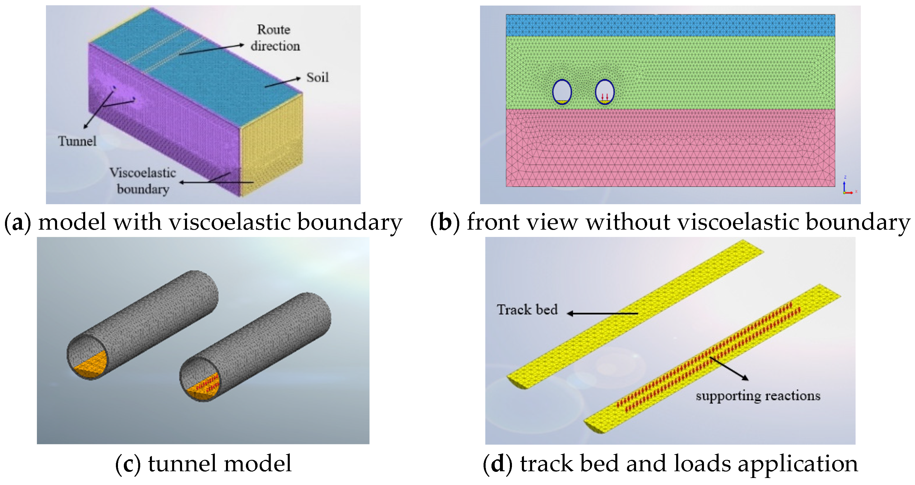
2.2. Track Bed–Tunnel–Soil Coupled FE Model

Based on metro line 3 in Tianjin, a track bed–tunnel–soil coupled FE model was established to calculate the ground vibration using MIDAS/GTS. A hybrid prediction method that combines numerical simulations and measured data was used to analyse and evaluate the vibration reduction and isolation effects of the comprehensive control method for metro-induced ground vibrations.
The size of the model was 100 m (length) × 40 m (width) × 40 m (height), and the soil was divided into three layers; the on-site geological survey results are presented in Table 1. The tunnel was a double-track double-hole shield tunnel with a buried depth of 15 m, diameter of 6 m and segment thickness of 0.3 m. The reinforced-concrete tunnel lining had a Young’s modulus of E = 3 . 5 × 10 10   Pa , Poisson’s ratio of 0.25 and density of 2500 kg/m3. A concrete roadbed was poured into the inverted arch of the tunnel, and the foundation backfill and roadbed plate had a dynamic elastic modulus of E = 4.2 × 10 10   Pa , Poisson’s ratio of 0.3 and density of 2500 kg/m3. All the parts in this FE model were considered as elastic and isotropic.
A tetrahedral grid was adopted for the model, divided into a small grid in the near field, a large grid in the far field and a transitional grid in the middle based on the distance from the vibration source. The grid size of the roadbed and tunnel was 0.3 m, and the grid sizes of the first and second layers of soil were divided from the tunnel to the far field by 0.3~0.6~1.2 m. The grid size of the bottom layer of soil was 2 m. The final number of grids for this model was 103428. Artificial viscoelastic absorption boundaries [6,60] were adopted to eliminate the boundary effect of vibration wave propagation. The setting of viscoelastic artificial boundaries is achieved by setting spring-damping elements on the variable interface. The stiffness and damping coefficients of the boundary layer are listed in Table 2, which could be calculated by the equations as follows [61,62]. The final established FE analysis model is shown in Figure 4.
k i = 2 G i r i A i ;    c i = ρ i C p i A i ;  
where ki and ci are the stiffness coefficient and the damping coefficient of the boundary, respectively. Gi, ρi and Cpi are the shear modulus, density and compressive wave velocity of soil, respectively. Ai is the area represented by control node i. ri is the distance from wave source to artificial boundary node i.

3. Field Measurements and Model Verification

Field measurements were performed to determine the ground vibration caused by a metro train running on an ordinary track of Tianjin metro line 3 to calibrate the correctness and accuracy of the model calculations. The map of the test section is shown in Figure 5.

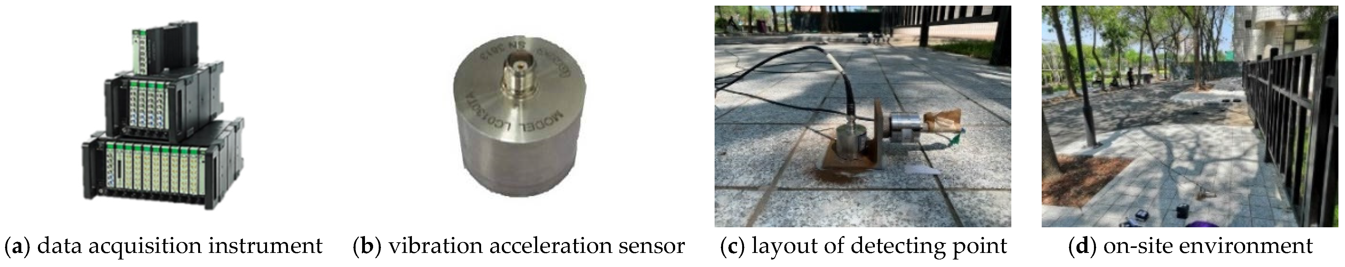
3.1. Outline of Measurements

The detection point was at a surface location 36 m from the centreline of the metro line, whose tunnel was a double-track double-hole shield straight tunnel with a buried depth of 15 m, diameter of 6 m and segment thickness of 0.3 m. The ground at the layout of the measuring point is flat and free from potholes, and motor vehicles and pedestrians are rare here, so had little interference with the testing. Two accelerometers were installed at the detection point in both the vertical and horizontal directions. Lance AS0130 series vibration acceleration sensors with a test range of 0.12 g and frequency range of 0.5–1000 Hz, and a 3160-A-042 multi-channel data acquisition instrument from Danish B&K company, were used to record the ground vibration accelerations induced by subway trains running on ordinary tracks at 54 km/h. The sampling frequency of the field test was set as 1024 Hz, which could obtain the ground acceleration below 512 Hz in the frequency domain according to the Nyquist rule. Due to the focus of this paper being on train-induced environmental vibration issues, focusing on the frequency range of 1–100 Hz and considering the efficiency of subsequent FE calculations, the results shown in this paper are only below 100 Hz. The tested data was processed by Coinv Dasp V11 software. Because of the possibility of signal leakage caused by time-domain signal truncation, the Hanning window, which is suitable for processing non-periodic continuous signals, was used when we transformed the tested time-history signal into the frequency domain, which could be directly selected in the software to eliminate high-frequency interference and energy leakage. The Hanning window function Hanning(n) is shown below.
H a n n i n g ( n ) = { 0.5 0.5 cos ( 2 π n N 1 ) , 0 n N 1 0 , else
where n = 1, 2, …, N − 1 is the serial number of the window function; N is the total length of the window
The testing equipment and on-site layout are shown in Figure 6. The tested metro train, similar to the model, consisted of six carriages, and the parameters of the metro train and ordinary track are listed in Table 3.
The established prediction model was used to numerically calculate the surface vibration response under the test conditions. The steel spring stiffness under the slab in the train–FST model was set to the maximum value (106 MN/m) to determine the fastener reaction force of all fasteners within the range of the FE model. The action of the moving train results in a certain time difference in the support reaction of each fastener as the train passes through the sequence of fasteners. After calculating the support reaction force of each corresponding fastener within the range of the FE model via the established train–FST model, the reaction forces were then applied in the actual spatial order in the form of point loads to certain positions of the corresponding fasteners on the track bed in the FE model. A subsequent analysis and calculation could be carried out. A typical fastener reaction force calculated using the vehicle rail model is shown in Figure 7. Subsequently, the calculated reaction force of the entire set of fasteners was applied as the excitation load in the actual spatial sequence to the track bed–tunnel–soil FE model, and the vibration acceleration of the ground detection points was computed. The Rayleigh damping assumption was adopted for the soil, and the damping ratio was set to ξ = 0.03. Because the focus of this study was on frequencies ranging from 1 to 100 Hz, the Rayleigh damping constants could be calculated using α = 0.373 and β = 9.454 × 10⁻⁵. A direct integration method was used to calculate the ground vibration response with a calculation time of 11 s, covering the passing time of the entire train. When using a FE model for calculation, both the calculation accuracy and efficiency need to be considered. The shorter the integration step, the higher the theoretical analysis frequency, but the longer the calculation time. Based on the previous study [6,10], stable calculation results can be obtained within the frequency range of environmental vibration concern (1–100 Hz) by taking the integration step as 0.002 s, which theoretically enables an effective analysis frequency to 250 Hz. Therefore, the integration step applied in this paper is 0.002 s.

3.2. Model Verification

Figure 8 shows a comparison between the ground vertical acceleration at the detection point calculated using the prediction model and field-measured results. The results obtained via model calculations in the time domain and the one-third octave (1/3 oct) band spectra are consistent with the on-site measurement results, demonstrating the accuracy and reliability of the prediction model. Meanwhile, due to differences between the US spectrum and rail irregularity in the actual testing conditions in our paper, the results calculated by the model and obtained by testing had differences. The difference between the irregularities considered in the model and existing in the test is one of the main causes. But the calculated results could be used as the excitation source for the FE model when the environmental vibration issues were discussed, and the established model can be applied to further analysis and calculations in the following sections.

4. Case Study and Analysis of Vibration Control Effect
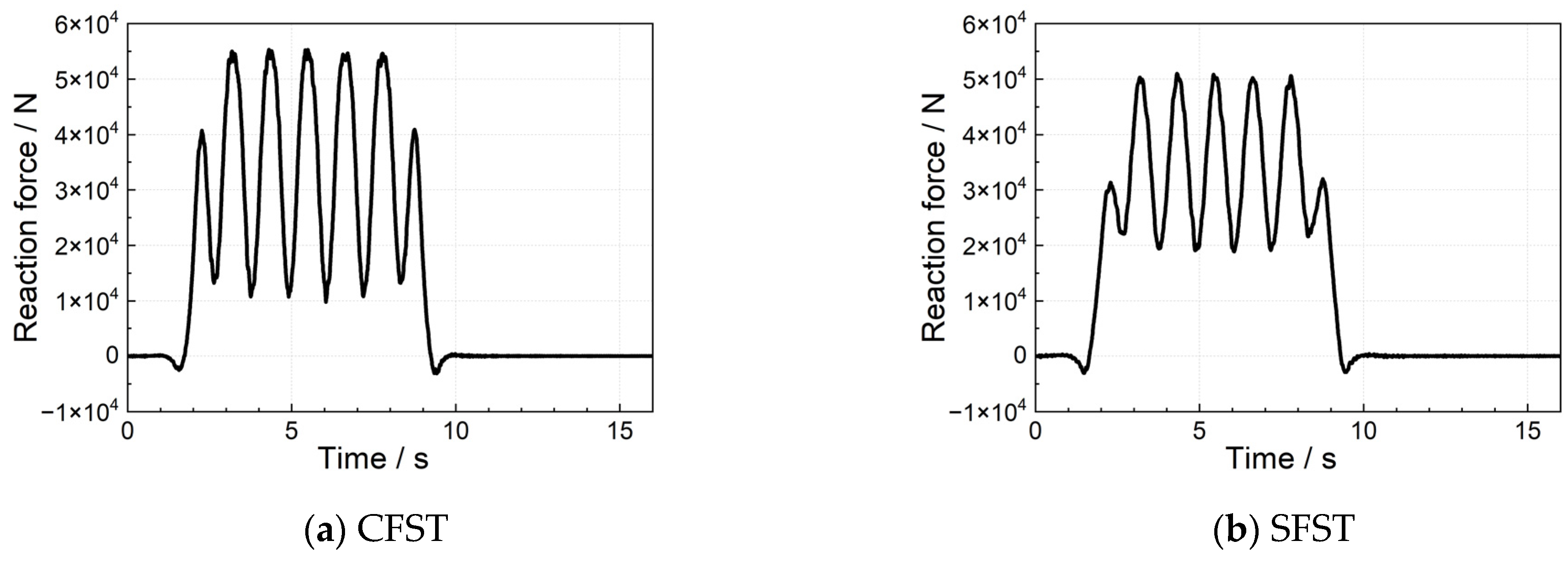
In response to the apparent amplification of ground vibration at the natural frequency of the FST owing to its application, the vibration reduction effect of a new type of FST was analysed by adjusting the support parameters of the steel springs and the quality of the floating slab. Subsequently, frequency matching was considered to design periodic row piles, and the effect of a vibration control method that combines FST with periodic row piles was examined. The ground vibration of each case was calculated via the established FE model, whose excitation source is the support reactions of the steel springs. The difference in each calculation condition is achieved through inputting different excitation forces to the FE model, which need to be calculated by changing the parameters of the steel-spring FST in the train–FST coupled model.

4.1. Design of FST

According to structural dynamics, the natural frequency of the FST is mainly determined based on the stiffness of the steel spring under the slab and the mass of the slab. The damping of the steel spring influences the peak vibration of the track. The stiffness and damping of the steel spring were decreased and increased, respectively, to broaden the vibration isolation frequency band and to reduce the resonance peak of the FST. The slab thickness was increased to increase the track mass. The parameters of the adjusted FST (called the special FST [SFST]) and existing conventional FST (CFST) are listed in Table 4. The typical reaction forces of the steel spring for the two types of FSTs, calculated using the 3D train–FST coupled model in the time domain, are shown in Figure 9. It should be noted that, since the mathematical mode superposition method is used to represent and solve the displacement response of the rails and floating slab, and the floating slab is simulated using a thin plate model, it is necessary to determine the number of modes required for calculation. In the frequency range of less than 100 Hz that the environmental vibration problems focus on, when the rail mode is set as 10 and the thin plate modes along, and perpendicular to, the direction of train travel are, respectively, set as 20 and 10, the calculation accuracy requirements can be satisfied [55]. Compared to the CFST, the range of change of the steel spring reaction force under the SFST decreased, which can improve the fatigue resistance of the steel spring and reduce the impact of vibration on the surrounding environment from the vibration source.
Figure 10 shows a comparison between the model calculation results for the ground vertical vibration acceleration under ordinary track conditions and the two types of FST conditions. Both types of FSTs significantly decreased the ground vibration acceleration, and the RMS value of vibration acceleration is reduced by one order of magnitude. The vibration control effect of the SFST is better, because the steel spring support reaction forces under this condition are smaller than the condition with the CFST, which can be seen in Figure 9. In addition, the ground vibration exhibited amplification near the natural vibration frequency of the FST. After adopting the SFST, the natural vibration frequency of the track decreased from 10 to 8 Hz, widening the effective vibration reduction frequency band of the track. Moreover, the ground vibration near the natural vibration frequency of the FST decreased by approximately 5–8 dB. However, the amplification of the ground vibration at the natural frequency of the FST did not change.

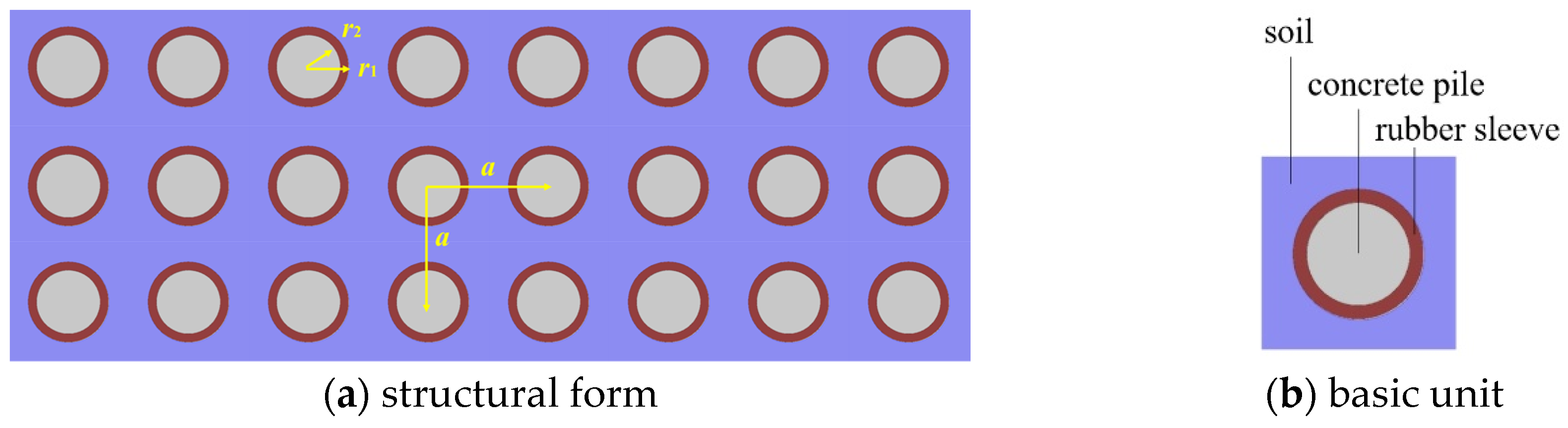
4.2. Design of Periodic Row Piles

According to the previous analysis, ground vibrations can be significantly suppressed after laying down a steel-spring FST. However, the ground vibration increased in the frequency range of 6–12 Hz owing to the resonance effect of the FST. Periodic vibration isolation row piles were designed and used to control ground vibration in the full-frequency band to further control the vibration in this frequency band, using a collaborative approach of vibration source reduction and propagating path isolation.
The distribution of the local resonance-type row piles was designed using the principle of phononic crystals, as shown in Figure 11. This type of pile consists of a rubber sleeve and a concrete pile, which can be prefabricated in the factory. As for the prefabrication and practical engineering of the row piles, the concrete part could be first inserted into the rubber sleeve and prefabricated in the factory to obtain the row piles with the proposed form. Then, according to practical application requirements and on-site conditions, the application of row piles in engineering can be achieved via an open excavation and backfilling method or by drilling holes with a width greater than the pile diameter before inserting the piles.
The design goal of the row piles was to generate a bandgap that could cover the natural frequency of the FST, such that the row piles could be set according to this parameter and arranged to block vibration propagation in the soil at a frequency of approximately 8 Hz. Based on the Bloch–Floquet theory and plane wave expansion method, the inner and outer diameters r1 and r2 of the cylindrical piles and the pile arrangement period constant a were calculated. The detailed calculation principles and process can be found in [63,64]. COMSOL Multiphysics 5.3a (a commercial FE software) was used to solve the bandgaps in the row piles. The parameters of the rubber sleeve were as follows: E = 0.3 MPa, v = 0.463, ρ = 1300 kg/m3, Vp = 969 m/s (P-wave velocity) and Vs = 39 m/s (S-wave velocity). The parameters of the concrete pile were E = 35 GPa, v = 0.25, ρ = 2500 kg/m3, Vp = 4545 m/s and Vs = 2688 m/s.
When the pile was arranged in three rows using a square lattice and the period constant a = 1.5 m, the inner radius of the concrete and the outer radius of the rubber were r1 = 0.4 m and r2 = 0.5 m, respectively, and the bandgap was generated at 7–9 Hz, as shown in Figure 12. The lines in this figure means the vibration modes of the soil-piles coupled system. When there is no vibration mode in a certain frequency band, the vibration waves in that frequency band cannot propagate within this system. That is, the row of piles can be set according to these parameters and arrangements to prevent vibration propagation in the 7–9 Hz frequency band of the soil.
To determine the length of the pile, two steps were considered. Firstly, according to the reference [63], when the tunnel is buried at a depth of 0.8λsv–1.4λsv, the length of the pile is better if longer than 1.6λsv to achieve a good vibration control effect, where the λsv represents the shear wavelength in the first layer of soil corresponding to the centre-frequency of the bandgap, and the calculated pile length was 24 m. Therefore, the pile length should be around 24 m. Secondly, the FE model was applied to calculate the ground vibration acceleration response under several conditions of pile lengths of 16 m, 20 m, 24 m and 28 m, respectively, shown in Figure 13.
It can be seen from this figure that, when the pile length is 24 m and 28 m, the difference in ground vibration acceleration is small. But when the pile length decreases to 20 m (shorter than the distance from the ground to the bottom of the tunnel), the ground vibration significantly increases, which means that the vibration reduction effect of the row piles is significantly reduced. Finally, the length of the pile was determined as 24 m.
Based on the calculated design parameters of the periodic row piles, a periodic row pile model was inserted into the track bed–tunnel–soil FE analysis model, as shown in Figure 14. The piles were simulated using solid units, and the pile–structure interaction was simulated using a common node force. The grid size of the periodic row piles was 0.6 m. Next, the ground vibration acceleration response at the detection point under SFST conditions was calculated using this model.

4.3. Analysis of Ground Vibration-Reduction Effect

Figure 15 shows a comparison of the ground vertical acceleration at the detection point calculated using the model under the SFST conditions before and after the periodic row piles were installed in the time domain. Figure 16 shows a comparison of the one-third octave curves of the calculated ground vertical vibration acceleration under the normal track, SFST and comprehensive vibration reduction and isolation conditions.
After using the local resonant periodic row piles, the ground vibration acceleration in the time domain decreased compared with that before using the row piles, with a peak vibration acceleration decrease of approximately 10% and RMS value decrease of 0.2 × 10⁻⁴ m/s2 (Figure 15 and Figure 16). In the frequency domain, the vibration waves in the 7–9 Hz frequency range were effectively blocked by the periodic row piles, resulting in a decrease of approximately 3–5 dB for the ground vibration acceleration near the natural vibration frequency of the SFST (6–12 Hz) compared with when row piles were not used. Furthermore, the ground vibration acceleration was significantly lower than the acceleration under ordinary track conditions at the natural vibration frequency of the SFST. The use of periodic row piles eliminated the adverse effect of the FST on the increase in ground vibration in the frequency range near its natural frequency. The combined control method proposed in this study controls ground vibrations induced by metro train operations in the full-frequency range.
Furthermore, the material composition of the row piles was varied to determine the low-frequency vibration control effect on the ground based on the vibration control collaborative method. Local resonance row piles were replaced with hollow row pipe piles. Specifically, the rubber was replaced with concrete, and the original concrete pile position was designed to be hollow. The ground vibration accelerations at the detection point under the conditions of the SFST only, SFST with local resonance row piles and SFST with rows of hollow pipe piles were calculated using the model (Figure 17).
The method with hollow row pipe piles could further reduce the ground vibration in the time domain, with an RMS value decrease of 0.12 × 10⁻⁴ m/s2 (Figure 17). Furthermore, from a frequency-domain perspective, the vibration in the 7 Hz low-frequency range significantly decreased by 4–10 dB, and the ground vibration of other frequency bands did not change compared to the condition comprising the local resonance row piles. At the natural frequency of the SFST, the ground vibration level was still lower than that of the ordinary track condition when the combined control method of the SFST and hollow row pipe piles were used, although it was slightly higher than that of the control method combined with local resonance row piles. Overall, the comprehensive vibration control method of the FST with hollow row pipe piles can control ground vibration in the full-frequency range, and it is more effective than other methods in low-frequency vibration control.

5. Conclusions

The commonly used steel-spring floating slab track can effectively control environmental vibration in the frequency band higher than 2  times its natural frequency, but the ground vibration is universally amplified at the natural frequency of the tracks, which has a significant negative impact on the normal use of precision instruments and other aspects. A novel ground vibration control method that considers frequency matching for environmental vibrations in combination with metro vibration source reduction and propagation path isolation was developed in this paper. Two types of periodic row piles were designed based on the Bloch–Floquet theory, and special FSTs, a 3D train–FST coupled model in the frequency domain established for the first time and a 3D track bed–soil–row-pile coupled FE model, were established to evaluate the effectiveness of the proposed vibration control method. This joint vibration control method not only solves the control problem of low-frequency vibration (especially the vibration around the natural frequency of the FST), but also achieves full-frequency ground vibration control, which could provide a solution to the difficult problem of train-induced ground vibration that is currently prevalent. The main conclusions of this study are as follows.
(1)
CFSTs can reduce the frequency vibration level by up to 40 dB, but vibration amplification occurs at 10 Hz, with an amplification of approximately 8 dB. After thickness adjustment, damping and FST stiffness reduction, the natural frequency of the FST shifts to a low frequency of 8 Hz, and the ground vibration decreases by approximately 5–8 dB in the frequency band near the natural frequency of the FST, but the vibration amplification does not be change.
(2)
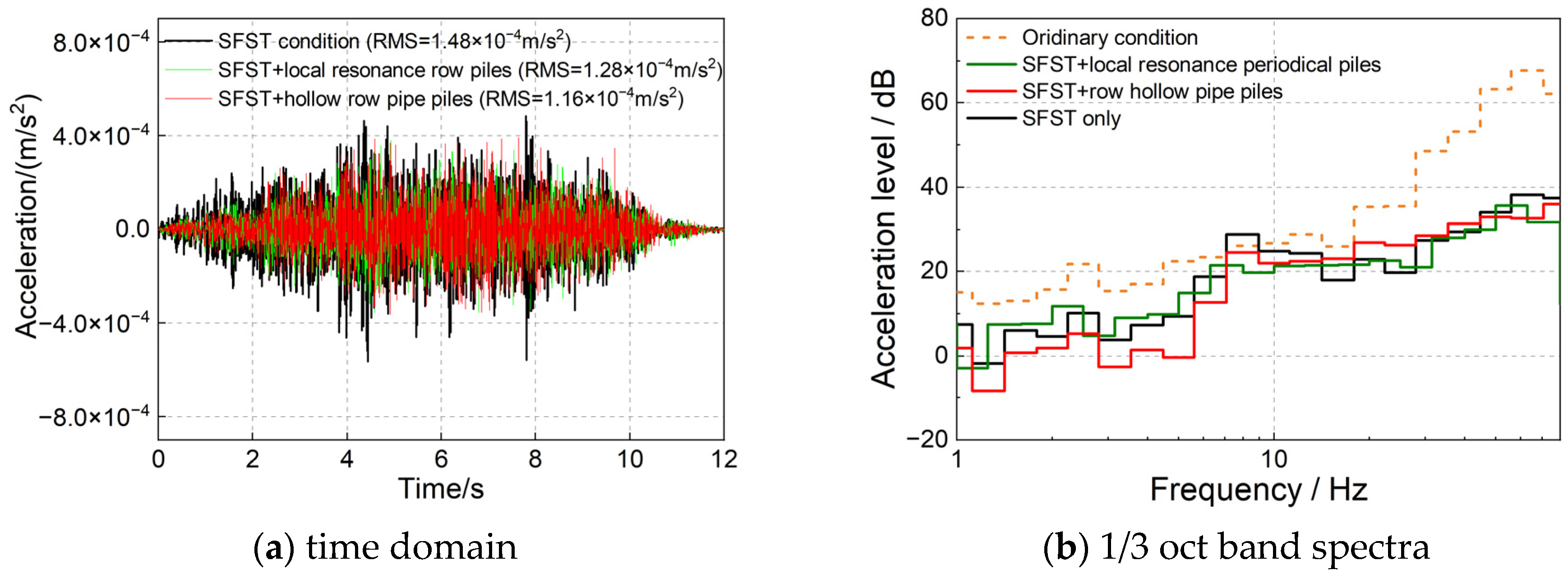
The use of FST can significantly decrease the ground vibration acceleration, and the RMS value of vibration acceleration can be reduced by one order of magnitude. Adding row piles in FST lines can further reduce the RMS value of the ground vibration response by approximately 0.2 × 10⁻⁴ m/s2.
(3)
The designed local resonance periodic row piles, whose bandgap range is adjusted to 7–9 Hz, can effectively reduce ground vibration at the natural frequency of the FST, with a decrease of 3–5 dB, which is lower than the ground vibration level under ordinary track conditions.
(4)
Replacing local resonance-type row piles with hollow pipe piles significantly decreases the ground vibration below 7 Hz, which can be reduced by 4–10 dB compared with the conditions for local resonance row piles. This also decreases the ground vibration amplification at the natural vibration frequency of the FST, and the vibration level is lower than that of the ordinary track condition at this frequency.
(5)
The proposed comprehensive vibration control method that considers frequency matching and combines vibration reduction from the vibration source and propagation path solves the ground vibration amplification problem at the natural frequency of the FST in metro lines. Compared with ordinary tracks, the frequency vibration can be decreased by 4–12 dB in the frequency band below 20 Hz and by 10–35 dB in the frequency band above 20 Hz, realising ground vibration control in the full-frequency band. This study provides a new and effective method for vibration control in scenarios such as when using precision instruments.

Author Contributions

Conceptualization, B.J. and C.Q.; methodology, J.L., M.M. and W.H.; software, X.T. and B.J.; validation, S.W. and X.T.; formal analysis, C.Q. and X.T.; investigation, X.T. and S.W.; data curation, W.H. and S.W.; writing—original draft preparation, X.T.; writing—review and editing, X.T. and W.H.; supervision, C.Q. and M.M.; project administration, J.L.; funding acquisition, B.J. and M.M. All authors have read and agreed to the published version of the manuscript.

Funding

This research was funded by the National Key R&D Program of China (Grant Number: 2022YFB2603400), Tianjin Science and Technology Plan Project (Grant Number: 22JCQNJC01710), Beijing Natural Science Foundation (Grant Number: L221023), and the Science and Technology Development Project of China Railway Design Corporation (Grant Number: 2021A241005).

Institutional Review Board Statement

Not applicable.

Informed Consent Statement

Not applicable.

Data Availability Statement

Data is contained within the article.

Conflicts of Interest

Xinyu Tan, Bolong Jiang, Chunyu Qi, Jizhao Liu, Wenlin Hu and Shaolin Wang were employed by China Railway Design Corporation (China). The remaining authors declare that the research was conducted in the absence of any commercial or financial relationships that could be construed as a potential conflict of interest. The authors declare that they have no known competing financial interests or personal relationships that could have appeared to influence the work reported in this paper. The funder had no role in the design of the study; in the collection, analysis, or interpretation of data, in the writing of the manuscript, or in the decision to publish the results.

References

  1. Qian, X.; Qu, W. Experimental and Numerical Studies of Metro Train-Induced Vibrations on Adjacent Masonry Buildings. Int. J. Struct. Stab. Dyn. 2015, 16, 1550067. [Google Scholar] [CrossRef]
  2. Sadeghi, J.; Haghighi, E.; Esmaeili, M. Performance of under foundation shock mat in reduction of railway-induced vibrations. Struct. Eng. Mech. 2021, 78, 425–437. [Google Scholar] [CrossRef]
  3. Ma, M.; Li, M.; Qu, X.; Zhang, H. Effect of passing metro trains on uncertainty of vibration source intensity: Monitoring tests. Measurement 2022, 193, 110992. [Google Scholar] [CrossRef]
  4. Yang, J.; Zhu, S.; Zhai, W.; Kouroussis, G.; Wang, Y.; Wang, K.; Lan, K.; Xu, F. Prediction and mitigation of train-induced vibrations of large-scale building constructed on subway tunnel. Sci. Total Environ. 2019, 668, 485–499. [Google Scholar] [CrossRef] [PubMed]
  5. Marco, Z.; Giuseppe, C.P.; Giuseppe, T.; Marco, S. On the Influence of Shallow Underground Structures in the Evaluation of the Seismic Signals. Ing. Sismica 2021, 38, 23–35. [Google Scholar]
  6. Ma, M.; Liu, W.; Qian, C.; Deng, G.; Li, Y. Study of the train-induced vibration impact on a historic Bell Tower above two spatial overlapping metro lines. Soil Dyn. Earthq. Eng. 2016, 81, 58–74. [Google Scholar] [CrossRef]
  7. Sadeghi, J.; Esmaeili, M. Safe distance of cultural and historical buildings from subway lines. Soil Dyn. Earthq. Eng. 2017, 96, 89–103. [Google Scholar] [CrossRef]
  8. Gupta, S.; Degrande, G.; Lombaert, G.; Liu, W. Prediction of vibrations induced by underground railway traffic in Beijing. J. Sound Vib. 2008, 310, 608–630. [Google Scholar] [CrossRef]
  9. Ding, D.; Gupta, S.; Liu, W.; Lombaert, G.; Degrande, G. Prediction of vibrations induced by trains on line 8 of Beijing metro. J. Zhejiang Univ.-Sci. A 2010, 11, 280–293. [Google Scholar] [CrossRef]
  10. Ma, M.; Jiang, B.; Liu, W.; Liu, K. Control of Metro Train-Induced Vibrations in a Laboratory Using Periodic Piles. Sustainability 2020, 12, 5871. [Google Scholar] [CrossRef]
  11. Liang, R.; Ding, D.; Liu, W.; Sun, F.; Cheng, Y. Experimental study of the source and transmission characteristics of train-induced vibration in the over-track building in a metro depot. J. Vib. Control 2022, 29, 1738–1751. [Google Scholar] [CrossRef]
  12. Huang, S.; Chen, Y.; Zou, C.; Jian, S. Train-induced environmental vibrations by considering different building foundations along curved track. Transp. Geotech. 2022, 35, 100785. [Google Scholar] [CrossRef]
  13. Colaço, A.; Castanheira-Pinto, A.; Costa, P.A.; Ruiz, J.F. Combination of experimental measurements and numerical modelling for prediction of ground-borne vibrations induced by railway traffic. Constr. Build. Mater. 2022, 343, 127928. [Google Scholar] [CrossRef]
  14. Farahani, M.; Sadeghi, J.; Jahromi, S.; Sahebi, M.M. Modal based method to predict subway train-induced vibration in buildings. Structures 2023, 47, 557–572. [Google Scholar] [CrossRef]
  15. Sadeghi, J.; Vasheghani, M.; Khajehdezfuly, A. Propagation of structure-borne noise in building adjacent to subway lines. Constr. Build. Mater. 2023, 401, 132765. [Google Scholar] [CrossRef]
  16. Faizan, A.A.; Kırtel, O.; Çelebi, E.; Zülfikar, A.C.; Göktepe, F. Experimental validation of a simplified numerical model to predict train-induced ground vibrations. Comput. Geotech. 2022, 141, 104547. [Google Scholar] [CrossRef]
  17. Auersch, L. Different Types of Continuous Track Irregularities as Sources of Train-Induced Ground Vibration and the Importance of the Random Variation of the Track Support. Appl. Sci. 2022, 12, 1463. [Google Scholar] [CrossRef]
  18. Tao, Z.Y.; Zou, C.; Yang, G.R.; Wang, Y.M. A semi-analytical method for predicting train-induced vibrations considering train-track-soil and soil-pile-building dynamic interactions. Soil Dyn. Earthq. Eng. 2023, 167, 107822. [Google Scholar] [CrossRef]
  19. Li, X.; Chen, Y.; Zou, C.; Wu, J.; Shen, Z.; Chen, Y. Building coupling loss measurement and prediction due to train-induced vertical vibrations. Soil Dyn. Earthq. Eng. 2023, 164, 107644. [Google Scholar] [CrossRef]
  20. Cheng, Z.; Zhang, Q.; Shi, Z. Floating slab track with Inerter Enhanced Dynamic Vibration Absorbers. Veh. Syst. Dyn. 2023, 61, 589–615. [Google Scholar] [CrossRef]
  21. Ngo, T.; Indraratna, B. Mitigating ballast degradation with under-sleeper rubber pads: Experimental and numerical perspectives. Comput. Geotech. 2020, 122, 103540. [Google Scholar] [CrossRef]
  22. Zeng, Y.; Pan, P.; Zhang, D.; Yang, J. Experimental study of isolation in the backfill zone of the foundation pit (IBF) method to reduce ground-borne vibration in buildings. Eng. Struct. 2020, 202, 109740. [Google Scholar] [CrossRef]
  23. Sun, X.; Ma, M.; Jiang, B.; Cao, R. Ground vibration from freight railway: Environmental impact and potential mitigation measure at propagation path. Environ. Sci. Pollut. Res. 2022, 29, 44364–44377. [Google Scholar] [CrossRef] [PubMed]
  24. Sheng, T.; Bian, X.; Xiao, C.; Chen, Y.; Liu, G.; Li, Y. Experimental study on a geosynthetics isolator for the base vibration isolation of buildings neighboring metro transportation. Geotext. Geomembr. 2021, 49, 1066–1078. [Google Scholar] [CrossRef]
  25. Hemsworth, B. Reducing groundborne vibrations: State-of-the art study. J. Sound Vib. 2000, 231, 703–709. [Google Scholar] [CrossRef]
  26. Wei, K.; Liu, Z.; Liang, Y.; Wang, P. An investigation into the effect of temperature-dependent stiffness of rail pads on vehicle-track coupled vibrations. Proc. Inst. Mech. Eng. Part F J. Rail Rapid Transit 2017, 231, 444–454. [Google Scholar] [CrossRef]
  27. Dere, Y. Effectiveness of the floating slab track system constructed at Konya light rail. Measurement 2016, 89, 48–54. [Google Scholar] [CrossRef]
  28. Vogiatzis, K.; Kouroussis, G. Prediction and efficient control of vibration mitigation using floating slabs: Practical application at Athens metro lines 2 and 3. Int. J. Rail Transp. 2015, 3, 215–232. [Google Scholar] [CrossRef]
  29. Xia, H.; Chen, J.; Xia, C.; Inoue, H.; Zenda, Y.; Qi, L. An experimental study of train-induced structural and environmental vibrations of a rail transit elevated bridge with ladder tracks. Proc. Inst. Mech. Eng. Part F J. Rail Rapid Transit 2010, 224, 115–124. [Google Scholar] [CrossRef]
  30. Alabbasi, S.; Hussein, M.; Abdeljaber, O.; Avci, O. A numerical and experimental investigation of a special type of floating-slab tracks. Eng. Struct. 2020, 215, 110734. [Google Scholar] [CrossRef]
  31. Kuo, C.; Huang, C.; Chen, Y. Vibration characteristics of floating slab track. J. Sound Vib. 2008, 317, 1017–1034. [Google Scholar] [CrossRef]
  32. Hui, C.; Ng, C. The effects of floating slab bending resonances on the vibration isolation of rail viaduct. Appl. Acoust. 2009, 70, 830–844. [Google Scholar] [CrossRef]
  33. Zhu, S.; Yang, J.; Yan, H.; Zhang, L.; Cai, C. Low-frequency vibration control of floating slab tracks using dynamic vibration absorbers. Veh. Syst. Dyn. 2015, 53, 1296–1314. [Google Scholar] [CrossRef]
  34. Zhu, S.; Yang, J.; Cai, C.; Pan, Z.; Zhai, W. Application of dynamic vibration absorbers in designing a vibration isolation track at low-frequency domain. Proc. Inst. Mech. Eng. Part F J. Rail Rapid Transit 2017, 231, 546–557. [Google Scholar] [CrossRef]
  35. Zhu, S.; Wang, J.; Cai, C.; Wang, K.; Zhai, W.; Yang, J.; Yan, H. Development of a Vibration Attenuation Track at Low Frequencies for Urban Rail Transit. Comput. Aided Civ. Infrastruct. Eng. 2017, 32, 713–726. [Google Scholar] [CrossRef]
  36. Jin, H.; Liu, W. Experimental study on vibration reduction characteristics of ladder track with different arrangement of sleeper pads. J. Mod. Transp. 2015, 48, 73–78. [Google Scholar] [CrossRef]
  37. Zhao, Z.; Wei, K.; Cheng, F.; Li, H.; Wang, P. A theoretical vibration-reduction effect analysis of the floating slab track supported by nonlinear variable stiffness isolators and semi-active magneto-rheological dampers. Struct. Control Health Monit. 2021, 28, e2829. [Google Scholar] [CrossRef]
  38. Zhao, C.; Zheng, J.; Sang, T.; Wang, L.; Yi, Q.; Wang, P. Computational analysis of phononic crystal vibration isolators via FEM coupled with the acoustic black hole effect to attenuate railway-induced vibration. Constr. Build. Mater. 2021, 283, 122802. [Google Scholar] [CrossRef]
  39. Sheng, X.; Zhao, C.; Yi, Q.; Wang, P.; Xing, M. Engineered metabarrier as shield from longitudinal waves: Band gap properties and optimization mechanisms. J. Zhejiang Univ.-Sci. A 2018, 19, 663–675. [Google Scholar] [CrossRef]
  40. Sheng, X.; Zeng, H.; Shi, C.; Du, Y. A study on low-frequency vibration-mitigation performance of a phononic Crystal floating slab track. J. Vib. Shock 2022, 41, 36–42. (In Chinese) [Google Scholar] [CrossRef]
  41. Huang, J.; Shi, Z. Attenuation zones of periodic pile barriers and its application in vibration reduction for plane waves. J. Sound Vib. 2013, 332, 4423–4439. [Google Scholar] [CrossRef]
  42. Richart, F.E.; Hall, J.R.; Woods, R.D. Vibrations of Soils and Foundations; Prentice-Hall, Inc.: Upper Saddle River, NJ, USA, 1970. [Google Scholar]
  43. Shi, Z.; Huang, J. Feasibility of reducing three-dimensional wave energy by introducing periodic foundations. Soil Dyn. Earthq. Eng. 2013, 50, 204–212. [Google Scholar] [CrossRef]
  44. Wang, X.; Wan, S.; Nian, Y.; Zhou, P.; Zhu, Y. Periodic in-filled pipes embedded in semi-infinite space as seismic metamaterials for filtering ultra-low-frequency surface waves. Constr. Build. Mater. 2021, 313, 125498. [Google Scholar] [CrossRef]
  45. Ma, M.; Markine, V.; Liu, W.; Yuan, Y.; Zhang, F. Metro train-induced vibrations on historic buildings in Chengdu, China. J. Zhejiang Univ.-Sci. A 2011, 12, 782–793. [Google Scholar] [CrossRef]
  46. Gordon, C.G. Generic Vibration Criteria for Vibration-Sensitive Equipment. In Proceedings of the SPIE’s International Symposium on Optical Science, Engineering, and Instrumentation, International Society for Optics and Photonics, Denver, CO, USA, 28 September 1999. [Google Scholar] [CrossRef]
  47. Mojtaba, V.; Javad, S.; Amin, K. Legal consequences of train-induced structure borne noise and vibration in residential buildings. Noise Mapp. 2022, 9, 170–188. [Google Scholar] [CrossRef]
  48. Standing Committee of the National People’s Congress. Law of the People’s Republic of China on the Prevention and Control of Noise Pollution; Standing Committee of the National People’s Congress: Beijing, China, 2022. [Google Scholar]
  49. Zou, C.; Moore, J.A.; Sanayei, M.; Tao, Z.; Wang, Y. Impedance Model of Train-Induced Vibration Transmission Across a Transfer Structure into an Over Track Building in a Metro Depot. J. Struct. Eng. 2022, 148, 04022187. [Google Scholar] [CrossRef]
  50. Xu, L.; Ma, M. Analytical solution of ground-borne vibration due to spatially periodic harmonic moving load on a tunnel embedded in layered soil. J. Zhejiang Univ.-Sci. A 2023, 24, 637–652. [Google Scholar] [CrossRef]
  51. Du, L.L. Study on the Theoretical Model of Coupled Vehicle & Track and Characteristics of Vibration Sources in a Curved Track; Beijing Jiaotong University: Beijing, China, 2018. [Google Scholar]
  52. Belotserkovskiy, P.M. Forced oscillations of infinite periodic structures: Applications to railway track dynamics. Veh. Syst. Dyn. 1998, 29 (Suppl. 1), 85–103. [Google Scholar] [CrossRef]
  53. Liu, W.; Du, L.; Liu, W.; Thompson, D.J. Dynamic response of a curved railway track subjected to harmonic loads based on the periodic structure theory. Proc. Inst. Mech. Eng. Part F J. Rail Rapid Transit 2018, 232, 1932–1950. [Google Scholar] [CrossRef]
  54. Zhai, W.; Wang, K.; Cai, C. Fundamentals of vehicle–track coupled dynamics. Veh. Syst. Dyn. 2009, 47, 1349–1376. [Google Scholar] [CrossRef]
  55. Tan, X.; Liu, W. Dynamic response analysis model of a 3D floating slab track with discrete supports infrequency domain. J. Vib. Shock 2021, 40, 183–189. (In Chinese) [Google Scholar] [CrossRef]
  56. Liu, W.; Li, C.; Ma, L.; Du, L. A frequency-domain formulation for predicting ground-borne vibration induced by underground train on curved track. J. Sound Vib. 2023, 549, 117578. [Google Scholar] [CrossRef]
  57. Anis, Z.; Hedrick, J.K. Characterization of Rail Track Irregularities. In Final Report; Contract No. DOT-TSC-1206; U. S. DOT: Boston, MA, USA, 1977. [Google Scholar]
  58. Zhu, Z.; Wang, L.; Gong, W.; Yu, Z. Comparative analysis of several types of vertical wheel/rail relationship and construction of an improved iteration model for train-track-bridge system. J. Cent. South Univ. (Sci. Technol.) 2017, 48, 1585–1593. [Google Scholar] [CrossRef]
  59. Wu, T.; Thompson, D. Theoretical Investigation of Wheel/Rail Non-Linear Interaction due to Roughness Excitation. Veh. Syst. Dyn. 2000, 34, 261–282. [Google Scholar] [CrossRef]
  60. Zucca, M.; Valente, M. On the limitations of decoupled approach for the seismic behaviour evaluation of shallow multi-propped underground structures embedded in granular soils. Eng. Struct. 2020, 211, 110497. [Google Scholar] [CrossRef]
  61. Gu, Y.; Liu, J.; Du, Y. 3D Consistent Viscous-spring Artificial Boundary and Viscous-spring Boundary Element. Eng. Mech. 2007, 24, 31–37. (In Chinese) [Google Scholar]
  62. Kouroussis, G.; Verlinden, O.; Conti, C. Finite-Dynamic Model for Infinite Media: Corrected Solution of Viscous Boundary Efficiency. J. Eng. Mech. 2011, 137, 509–511. [Google Scholar] [CrossRef]
  63. Jiang, B. Study on Periodic Piles for the Isolation of Train-Induced Environmental Vibration Based on Band Gap Theory; Beijing Jiaotong University: Beijing, China, 2019. (In Chinese) [Google Scholar]
  64. Li, Z.; Ma, M.; Liu, K.; Jiang, B. Performance of rubber-concrete composite periodic barriers applied in attenuating ground vibrations induced by metro trains. Eng. Struct. 2023, 285, 116027. [Google Scholar] [CrossRef]
Figure 1. Flowchart for using the proposed prediction model.
Applsci 13 12979 g001
Figure 2. Schematic of metro-train–FST coupled model.
Applsci 13 12979 g002
Figure 3. 3D mechanical model of FST.
Applsci 13 12979 g003
Figure 4. 3D track bed–tunnel–stratum FE analysis model.
Applsci 13 12979 g004
Figure 5. Location of measurement points and metro line direction map.
Applsci 13 12979 g005
Figure 6. Diagram of test equipment and on-site layout.
Applsci 13 12979 g006
Figure 7. Typical fastener reaction force.
Applsci 13 12979 g007
Figure 8. Comparison between model calculation and on-site measurement results of ground vibration acceleration.
Applsci 13 12979 g008
Figure 9. Typical reaction forces under two types of FSTs.
Applsci 13 12979 g009
Figure 10. Ground vertical vibration accelerations for different cases.
Applsci 13 12979 g010
Figure 11. Schematic of structural form and basic unit of local resonance low-frequency vibration isolation row piles.
Applsci 13 12979 g011
Figure 12. Bandgap calculation results.
Applsci 13 12979 g012
Figure 13. The ground vibration acceleration corresponds to different pile lengths.
Applsci 13 12979 g013
Figure 14. 3D track bed–tunnel–soil row pile FE model.
Applsci 13 12979 g014
Figure 15. Time histories of ground vibration acceleration with and without periodic row piles.
Applsci 13 12979 g015
Figure 16. One-third octave spectrum curves of ground vibration acceleration under three working conditions.
Applsci 13 12979 g016
Figure 17. Calculated ground vibrations under different working conditions.
Applsci 13 12979 g017
Table 1. Stratigraphic parameters.
No.Soil TypeThickness/mShear Wave
Velocity/(m·s−1)
Density
/(kg·m−3)
Poisson’s RatioYoung’s
Modulus/MPa
Shear Modulus/MPa
1Plain fill3.013019300.3588.032.6
2Silty clay20.029018800.45458.0157.9
3Silt20.036021000.36680.0250.0
Table 2. Coefficients of artificial viscous-spring boundary.
Stratum NumberSpring Stiffness CoefficientSpring Damping Coefficient
kx (kN/m3)ky (kN/m3)kz (kN/m3)cp (kN·s/m)cs (kN·s/m)
118,16214,005--527253
254,54342,059--1825550
384,73649,61950,7901564732
Table 3. Parameters of train and track.
ParameterValueParameterValue
mass of car body Mc4.3 × 104 kgstiffness of secondary suspension kt5.8 × 105 N/m
mass of bogie Mt3.6 × 103 kgdamping of secondary suspension ct1.6 × 105 Ns/m
mass of wheelset Mw1.7 × 103 kgstiffness of primary suspension kw1.4 × 106 N/m
wheel–rail contact constant G5.147 × 10−8 m/N2/3damping of primary suspension cw5 × 104 Ns/m
moment of inertia of car body
around x-axis J c x
1.7 × 10⁶ kgm2moment of inertia of wheelset
around z-axis J w y
706 kgm2
moment of inertia of car body
around y-axis J c y
2.205 × 10⁵ kgm2moment of inertia of bogie
around x-axis J t y
9.62 × 10³ kgm2
moment of inertia of car body
around z-axis J c z
1.28 × 10⁶ kgm2moment of inertia of bogie
around y-axis J t z
1206 kgm2
moment of inertia of bogie around z-axis J t x 2809 kgm2half-length between two bogies b6.3 m
static wheel–rail force P07 × 104 Nhalf-length between two wheelsets a1.1 m
length of carriage l19 mfastening stiffness kr65 MN/m
mass of rail m60.64 kg/mfastening damping cr30 kN/m
bending stiffness of rail EI6.625 MN·m2fastening spacing L0.6 m
loss factor of rail η0.01mass of slab ms2500 kg/m
steel spring spacing d1.2 melastic modulus of slab Es3.1 × 1010 N/m2
loss factor of slab ηs0.05
Table 4. Parameters of two types of FST.
ParameterCFSTSFST
slab thickness/m 0.40.54
slab length/m2525
slab width/m33
vibration isolator stiffness/(MN/m)6.95.5
vibration isolator damping/(MNs/m)0.030.05
Disclaimer/Publisher’s Note: The statements, opinions and data contained in all publications are solely those of the individual author(s) and contributor(s) and not of MDPI and/or the editor(s). MDPI and/or the editor(s) disclaim responsibility for any injury to people or property resulting from any ideas, methods, instructions or products referred to in the content.

