
Research on Environmental Vibration Induced by High-Speed Maglev Transportation

Maglev Transportation Engineering R&D Center, Tongji University, Shanghai 201804, China
*
Author to whom correspondence should be addressed.
Appl. Sci. 2024, 14(1), 413; https://doi.org/10.3390/app14010413
Submission received: 30 October 2023
/
Revised: 12 December 2023
/
Accepted: 28 December 2023
/
Published: 2 January 2024
(This article belongs to the Special Issue Recent Advances in Vehicle-Track-Ground Coupling Dynamics and Railway-Induced Ground Vibration)
Abstract
:As a novel form of railway transportation, maglev transportation has the advantages of a better curve negotiation ability and grade ability and lower noise and vibration than traditional urban wheel–rail transportation. Thus, it is suitable for use in urban public transportation. However, the levitation of the widely utilized electromagnet suspension (EMS) system relies on continuously active suspension force adjustment, which gives it vehicle–track-coupled vibration characteristics different to those of the traditional wheel–track transportation system. Despite many research studies focusing on maglev vehicle–track coupling vibration, the environmental vibration influences associated with the running of maglev trains are still unclear. When the vibration propagates to the surroundings beyond certain thresholds, it may lead to various vibration serviceability problems. Practical test results on the environmental vibration induced by maglev transportation are still not enough to generate convincing vibration propagation and attenuation laws. In this research, a series of in situ tests were carried out around the Shanghai maglev line; the results show that the viaduct bridge is helpful in reducing environmental vibration, and an empirical formula was proposed to predict the effect of viaduct column height. Due to the ground wave superposition, a vibration-amplifying zone was also found about 10 m away from the maglev line, in which the vibration magnitude was strong enough to be perceived by the surrounding occupants.
1. Introduction
In recent decades, with the increasing pressure of traffic congestion and environmental conservation, it has become necessary to encourage the development of public transportation, and the development of maglev transportation offers a new form of convenient high-speed urban railway transit.
The maglev transportation system utilizes magnetic force to provide contactless suspension, guidance, and propulsion. Thus, it reduces most of the mechanical friction and a large number of moving parts in the train [1]. Compared to the traditional forms of rail–wheel transportation, the maglev system has the advantages of lower noise and vibration, better curve negotiation and grade abilities, higher reliability, and lower maintenance costs, giving it potential for high-speed and long-distance transportation or transits across the city.
There are two major forms of magnetic levitation, utilizing either the attractive force between iron-core electromagnets and ferromagnetic rails or the repulsive force between superconductivity magnets and induced electric currents in conductive guideway components [2]. The former is known as electromagnetic suspension (EMS), and the latter is called electrodynamic suspension (EDS). EMS is the only form of suspension utilized in commercial maglev lines, such as the Shanghai high-speed maglev demonstration line, the Changsha medium-speed maglev line, and the urban transit maglev (UTM) in the Republic of Korea [3].
In the EMS system, the suspension of a maglev train is maintained by an active, controlled attractive force. To maintain a steady state, levitation relies on the conscious adjustment of the suspension force. Even when a maglev train is suspended statically on the guideway, the train and track still vibrate under the constantly changing force; this kind of coupling vibration is the most significant difference between maglev and traditional wheel–rail transportation, and modeling and controlling the vehicle–track vibration are still key and difficult points in maglev transportation studies.
During the running of a maglev train, the vehicle and railway track constantly vibrate and propagate the vibration to the surrounding environment, which affects the surrounding environment and may cause serviceability problems or even vibration pollution. When the vibration in a building is large enough or lasts long enough, people will perceive the vibration and feel annoyed, uncomfortable, or even panicked, eventually causing huge economic losses [4]. The transmission of traffic-induced vibration may have the potential to cause damage to surrounding structures, especially heritage buildings [5] and previously damaged buildings [6]. Even if the vibration is not large enough to cause damage, excessive environmental vibration may also affect instruments’ accuracy in nearby laboratories and factories [7], such as at Peking University, where equipment valued at CNY 400 million was affected by the opening of underground line 4. Therefore, it is necessary to study the vibration effects of maglev transportation.
In past decades, researchers have studied in detail the vibration effects of wheel–rail transportation. Xia et al. [8] conducted field tests and discovered that surface waves rather than longitudinal or transverse waves occupy the main components of vibration caused by railway traffic; the vibration magnitude under a 2 m depth is only 20–50% of that on the ground surface and reduces to 10–20% at a 4 m depth. Yan et al. [9] conducted an in situ test and an analysis of the environmental vibration induced by urban subway transit and found that the amplitude of the vibration vertical to the ground is higher and attenuates more slowly than horizontally. Moreover, there exists a vibration-amplifying zone at a certain distance from the subway track. The position of the zone is determined by the geological condition, depth of the tunnel, and mechanism of vibration, and an attenuation formula was proposed to predict subway environmental vibration. Cui et al. [10] studied the propagation laws of the environmental vibration induced by urban rail transit moving on the ground and proposed general propagation rules by comparing statistical data on environmental vibration in field tests. He et al. [11] established a simplified three-dimensional finite element model to simulate ground vibrations caused by metro trains; the numerical analysis results showed that vertical ground vibrations are generally larger than lateral vibrations in the area close to the central line of the railway, and they successfully simulated the vibration-amplifying zone caused by wave reflection and interference 20 m away from the railway’s central line. Ouakka et al. [12] compared different existing mitigation systems and provided a benchmark reference for the railway industry when searching for the best solution for a project.
Different from wheel–track transit, maglev transportation is fairly new, and the number of maglev lines is rather small; therefore, research on the vibration effects of maglev transportation is not quite sufficient. The research is based more on numerical simulations rather than in situ tests. Gao et al. [13] arranged vibration measurement points along and perpendicular to the maglev line and found that the ground vibration induced by a maglev train is far less than that caused by a wheel–track train, and the vibration will not obviously increase with the increase in train speed, as is the case for wheel–track transits. He et al. [14] measured the vibration magnitude 26–80 m away from a maglev line and utilized a logarithmic function to fit the vibration propagation law. Zhao et al. [15] proposed an interaction model of a maglev vehicle–bridge system to calculate dynamic magnetic forces between a maglev train and a guideway bridge and then used the force to calculate the ground vibration response. The numerical results showed that the ground vibration attenuation law is similar to that induced by wheel–rail vehicles, but there is no amplifying zone at about 25 m away from the track centerline. When the vehicle speed increased from 125 km/h to 430 km/h, the vibration level rose about 10 dB at the same point.
The research mentioned above generally showed the propagation and attenuation laws of the ground vibration induced by maglev transportations, but the lack of in situ tests may cause overfitting problems. Thus, the current research involved the following: (1) A series of in situ tests were conducted around the Shanghai high-speed maglev line, where practical vibration data from the running of maglev trains were gathered. (2) The vibration propagation law in the vertical direction was discovered, and an empirical formula related to height was proposed. (3) A ground vibration distribution graph was drawn using the measured data, and vibration propagation patterns different to those of wheel–track transportation were revealed.
2. Test Design
A test was conducted around the Shanghai high-speed maglev line, which was the first commercial maglev line to be operated anywhere in the world. The line began operation in 2002; it runs from the Longyang Road subway station to Pudong International Airport, with a total length of 29.88 km, a maximum design speed of 505 km/h, and a running speed of 430 km/h. The travel time is reduced to only 8 min from more than 1 h by metro; thus, the maglev line plays an important role in connecting the center of Shanghai to the international airport. As the maglev train departure interval is only 15–20 min, the line vibration is quite frequent, and it is therefore necessary to measure the maglev-transportation-induced environmental vibration along the line.
2.1. Test Site
The ground environment to be measured was around girder number 484. As one of the long-term health monitoring girders, the irregularity and deformation of the girder undergo annual measurement and maintenance; thus, any vibration-induced girder irregularity can be easily identified. The test site is also far from streets or subway lines, so the vibration around the line can be seen as mainly being induced by the running of maglev transport. A photo of the guideway girder is shown in Figure 1.
2.2. Test Equipment
According to previous test and simulation results, adequate measuring equipment was chosen. In the test, small-sized, long-range accelerometers (model INV9828; range 10 g, 0.2–2500 Hz, sensitivity g) were used to measure the vibrations on the guideway structures. High-precision but larger-sized accelerometers (model LC-0132 T; range 0.1 g, 0.05–500 Hz, sensitivity g) were chosen for measuring the ground vibrations. At all test points, the accelerometers were tightly fastened to the structure or ground surface and synchronized using a Lance INV3062C data acquisition instrument.
2.3. Test Point Layout
To investigate the propagation and attenuation laws of the environmental vibration induced by maglev transportation, test points were set on the guideway girder, column, and environmental ground surface. The specific layout details are provided in the following subsections.
2.3.1. Test Point Layout on Guideway Girder and Column
The test guideway girder is a 24.768 m simply supported beam. Acceleration test points were set along the vibration propagation route. The test points, in sequence, are the inner functional part (point A), the mid-span beneath the girder (point B), the end of the girder (points C and D), the girder bearing’s upper and lower boards (points E and F), and the center of the column foundation. The girder cross-section and the in situ accelerometer layout are shown in Figure 2 and Figure 3. All accelerometers were placed in the vertical direction.
2.3.2. Environmental Vibration Test Point Layout
According to existing research results, the environmental vibrations induced by wheel–track transit mainly consist of vertical surface waves [7,8], so only the vertical acceleration on the ground surface was measured in this study.
In previous in situ measurements, the researchers naturally assumed that the maximum acceleration occurs on the plane that passes through the column and is perpendicular to the railway line [16]. However, the maximum speed of a high-speed maglev is over 100 m/s, and the span of the railway is usually less than 30 m, so the ground vibration waves that propagate across the ground through different columns can easily superpose and interfere with each other, leading to complex ground vibration distributions around the maglev line. Therefore, in order to learn the practical propagation and attenuation rules of the ground vibration induced by maglev transportation, it is necessary to measure the vibration distribution in a two-dimensional area around the railway line. In this research, in order to determine the attenuation law with an increase in the distance, test points were set using polar coordinates. Besides the points along and transverse to the maglev line, directions of 30, 45, and 60 degrees from the maglev line were also considered, and the ground vibration acceleration at different distances in different directions was measured simultaneously.
A layout diagram and an in situ testing scene are shown in Figure 4 and Figure 5, in which the larger squares indicate the pile cap buried underground, the small squares indicate the column cross-section, and the small circles are test points. All of the accelerometers were mounted on paved surfaces in the vertical direction, and small and thin pieces of plasticine were used to make sure that the accelerometers were well attached to the ground.
2.4. Test Conditions
As shown in Figure 1, there are two guideway girders supported by a double-column pillar. During the daily routine of the maglev line, maglev trains run in both directions on both guideways. During the research, only vibrations induced by the running of maglev trains on the closest girder were considered. Table 1 provides the timetable of the trains that ran during the test procedure.
As the accelerometers were all set on girder A, this study focused mainly on the recordings taken when the maglev trains passed by girder A. Because the two girders have similar dynamic characteristics and were placed on the same bent cap, there was barely any difference in the ground vibration response no matter which girder the train passed over. Thus, the test number or girder number will not be specifically mentioned in the following analysis unless necessary.
3. Guideway Structure Vibration
While a maglev train is running, a vehicle–track-coupled vibration propagates from the functional parts to the girder and then to the surrounding environment through the bearing and column. In order to determine the environmental vibration influence of a maglev train, the vibration propagation law in guideway structures should be studied first.
The construction of railway lines through viaducts has many advantages, such as suitable ground conditions, saving ground space, being suitable for prefabrication and assembly, and reducing noise and vibration, so this approach is widely used in urban railway transit. As the substrata along the Shanghai maglev line are of loose deposits of the fourth period, mainly composed of saturated clay, silt, and sandy soil, all of the guideway girders are supported on viaducts using pile foundations [1]. While maglev trains are running, vibrations generated by vehicle–track interactions cannot directly propagate into the surrounding environment but must first pass through the bearing and column. Although it has been proven that viaduct structures can significantly reduce the vibration generated by wheel–track transit, how well it works in terms of maglev transportation still needs to be studied.
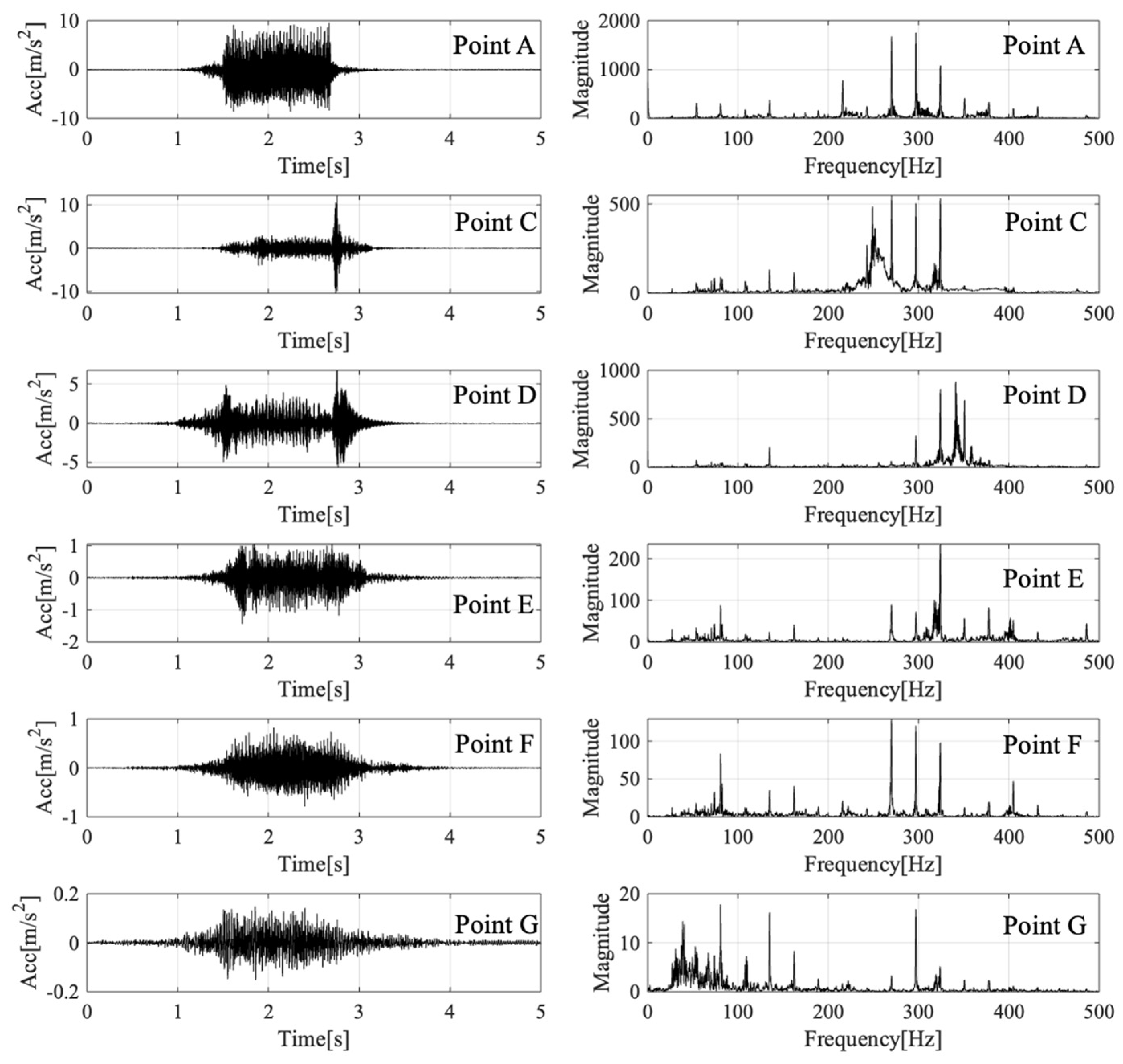
In this research, the test points along the path of vibration propagation included the inner functional part (point A), the end of the girder (points C and D), the upper board of the bearing (point E), the lower board of the bearing (point F), and the central area of the ground foundation (point G). The acceleration time history and frequency spectra calculated using fast Fourier transformation (FFT) of these test points in order of altitude, from high to low, are listed in Figure 6 (in sequence: points A, C, D, E, F, and G).
Observing the time histories above, with the propagation of the vibration, the peak acceleration reduces from around 10 m/s2 at the inner functional part to around 0.15 m/s2 at the center of the ground foundation; the attenuation along the guideway structure is quite obvious.
The vibration at the end of the girder (subgraph for points C and D) is quite large when a maglev train has just entered or just left the guideway girder. The peak acceleration can be as large as 10 m/s2, sometimes even up to 20 m/s2, but then it turns to a steady state at around 2–4 m/s2. As the guideway girders are mainly simply supported beams, the bevel and offset between adjacent girders, as well as the dynamic deformation induced by the running maglev train, lead to irregularity between the girders and cause these impacts.
When comparing the time history for the upper and lower boards of the bearing (subgraph for points E and F), it can be seen that, after the vibrations propagate through the bearing, although the peak acceleration does not change too much, the time history becomes smoother, which means that the bearing plays the clear role of a wave filter. As for the vibrations at the top and bottom of the column (subgraph for points F and G), it can be seen that the vibration is reduced by over 75% after propagating through the 10 m high column. This attenuation phenomenon proves that even the dynamic load of maglev transportation is different from that of traditional wheel–track transformations, and the viaduct structure is still useful to reduce the ground vibration level.
The last three subgraphs in Figure 6 compare the first two test points located on the guideway girder, and it can be seen that the time duration and free attenuation period are much longer. As the column and girder are both reinforced concrete with a similar elasticity modulus and damping ratio, it can be inferred that the difference is mainly caused by the wave superposition and interference from the adjacent two spans of the simply supported beam. In order to further investigate the rules of vibration propagation and attenuation, the frequency spectra of each acceleration record are shown in Figure 6.
From the frequency spectra above, it can be seen that, during the vibration propagation process along the guideway structure, the high-frequency components of the vibration attenuate rapidly; the low- and medium-frequency components take turns to dominate, and the major frequency range changes from 200–400 Hz to 20–100 Hz. Thus, the guideway structures, especially the column and pillar, act like low-pass filters in the vibration propagation process.
During the process of vibration propagation and attenuation, although the magnitude attenuated rapidly and the peak acceleration was no more than 0.2 m/s2 at the ground surface, the frequency components under 100 Hz, which are easily perceived by human beings, did not reduce too much. According to previous research on vibration serviceability and vibration comfort, people are more sensitive to low-frequency vibrations with a frequency range of 5–80 Hz [4]; thus, the vibration serviceability risk of maglev transportation cannot be ignored.
4. Environmental Ground Surface Vibration
In previous studies on the environmental vibration induced by urban railway transportation, researchers usually assume that ground vibration magnitude is only related to the transversal distance from the central railway line, regardless of the longitudinal distance from the column of the railway structure. This assumption ignores the superposition and interference of waves propagated from different columns. When the span is long enough and the train speed is slow, the vibration has enough decaying time, and the error caused by this assumption is acceptable. However, for high-seed maglev transportation with a speed of over 100 m/s and a span of less than 30 m, the ground vibration level in the whole ground plane should be considered.
In this part of the research, the propagation laws in different directions (0, 30, 45, 60, and 90 degrees from the central line) were measured and analyzed so that the environmental vibration propagation and attenuation laws for the whole ground plane could be revealed.
4.1. Vibration Propagation along the Maglev Line
As the high-speed maglev line is constructed on a viaduct throughout the whole line, the vibration induced by the vehicle–track system can only be propagated to the ground through the column and foundations; thus, the vibration may not be evenly distributed along the line. Although the construction of buildings under guideway girders is not permitted in high-speed design standards [17], many maintenance and controlling devices for maglev transportation are located just under the guideway line, which can also be affected by ground vibrations. Therefore it is necessary to determine the vibration levels under the guideway girder.
During the field test, vibration test points were set on the top of the foundation wall, which is located at the center of the line and has good contact with the ground. The distance of each test point was 0 m, 7.5 m, 10 m, and 12.5 m away from the foundation center (points G, H, I, and J in Figure 4), as shown in Figure 7. When a maglev train passed through the test area, the acceleration of each test point was measured. The time history results and frequency spectra analysis are shown in Figure 8 (listed in order of distance).
The test results indicate that the vibration magnitude is generally closer at different points, but with an increase in the distance, the peak acceleration slightly increases and then decreases. The maximum vibration does not occur at the center of the foundation or mid-span, but rather at around 7.5 m from the foundation center because of the traveling wave effect. As the guideway girder spans at the tested area were all 24.768 m and the adjacent girders’ structure dynamic characteristics were nearly the same, it can be inferred that the vibration has a symmetrical distribution at the other half of the span under the guideway girder.
Furthermore, by comparing the frequency spectra of each acceleration record in Figure 8, it can be clearly observed that, with the increase in the distance from the foundation center, the high-frequency components of the ground vibrations attenuate rapidly, as the ground acts as a low-pass filter in the process of vibration propagation. However, the frequency components range from 100 to 150 Hz at a distance of 7.5–12.5 m, which is larger than that at the center of the foundation. The superposition of the waves is most likely the reason for this acceleration-amplifying phenomenon.
4.2. Vibration Propagation Perpendicular to the Maglev Line
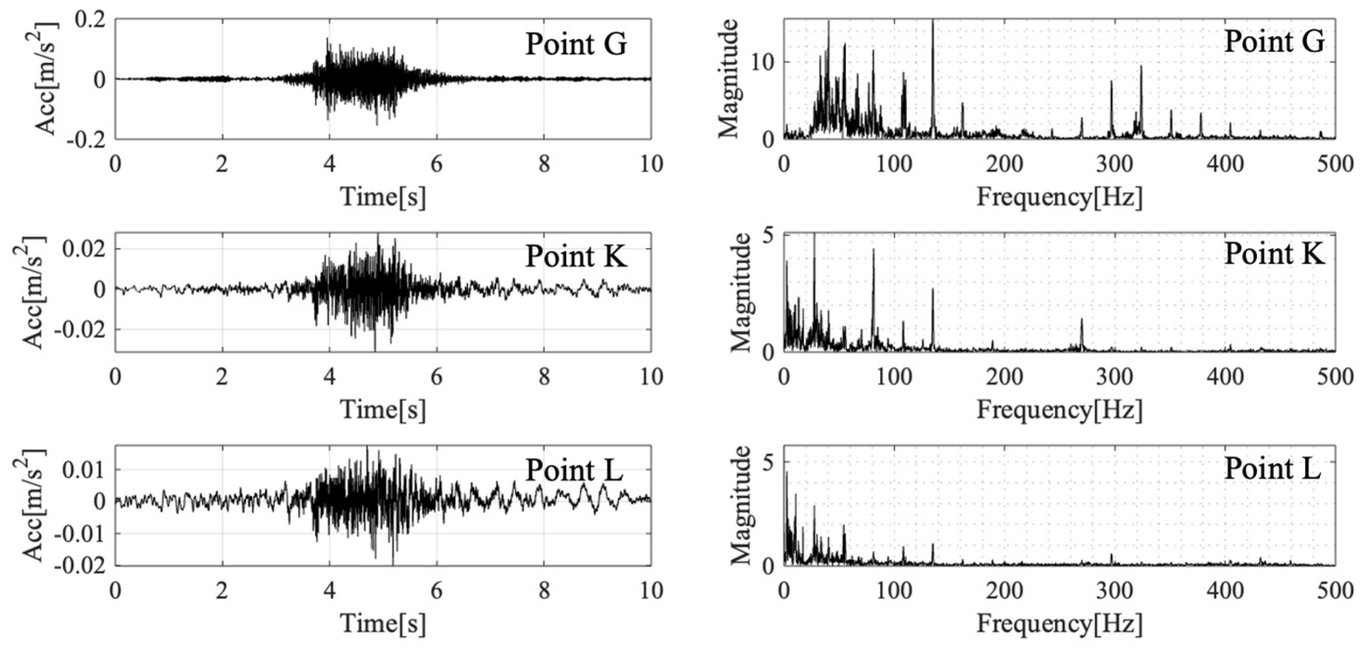
The direction perpendicular to the maglev line is most widely studied in previous research for both wheel–track and maglev transportation. Researchers usually ignore the traveling wave effect and assume that the points under the column have the largest vibration, which was found not to be so accurate in the former section. In spite of this, the direction perpendicular to the maglev line and column is still important to evaluate the ground vibration magnitude and is widely utilized in standards and criteria. In this research, test points with distances of 0 m, 7.5 m, and 10 m (points G, K, and L in Figure 4) were set to measure the ground acceleration when maglev trains passed through. The measured results and calculated frequency spectra are shown in Figure 9 (listed in order of distance).
Figure 9 above shows that, with the increase in the distance to the maglev line, the ground vibration attenuation speed is considerably quicker than that in the guideway structures. At the test point 10 m away from the maglev line, the peak acceleration reduces by over 90% compared to the foundation center, and it does not show any tendency towards an amplifying phenomenon. The peak acceleration 10 m away from the maglev line is no more than 0.015 m/s2, which is the perception threshold suggested by international standards based on the evaluation of human exposure to whole-body vibration [18]; thus, the ground vibration can barely be perceived at this distance if resonance does not occur.
The spectral analysis results clearly show that the major components of the maglev-induced vibration are in the high-frequency range, and they also have weak penetrating power in soft soil and sand. The high-frequency components of the ground vibration waves attenuate rapidly with the increase in the distance, with low-frequency components under 50 Hz mainly being reserved 10 m away from the maglev line.
4.3. Vibration Propagation in Whole Ground Surface
In order to measure the vibration magnitude of the whole ground plane around the maglev line, directions with angles of 30, 45, and 60 degrees from the maglev line were chosen. By measuring the ground acceleration response of the different distances in these directions, the vibration propagation and attenuation laws can be determined. The specific layout of the test points is given in Figure 4.
4.3.1. Vibration Propagation 30 Degrees from Maglev Line
To investigate the vibration propagation in the 30-degree direction, five test points were chosen with distances to the foundation of 0 m, 7.5 m, 10 m, 12.5 m, and 15 m (points G, M, N, O, and P in Figure 4) in sequence. The ground acceleration responses and frequency spectra are shown in Figure 10 (listed in order of distance).
In the time history records above, it can be seen that, when the ground vibration propagates 30 degrees from the maglev line, the trend of attenuation rapidly reduces and then maintains relative stability. At the first 10 m away from the foundation center, the peak value of acceleration rapidly reduces from near 1.5 m/s2 to about 0.01 m/s2, and then it maintains this peak value until the farthest test point. Meanwhile, as the test point layout is oblique to the maglev line, the vibration propagating from the column requires more time to reach each test point, leading to tiny time lags between the different subgraphs.
In order to determine the reason for this phenomenon, the frequency spectra of the logarithmic coordinates shown in Figure 10 were examined. It can be seen that, when the distance reaches 7.5 m, the frequency components over 200 Hz almost all disappear, and then at 10 m away, only vibration components under 10 Hz remain. As low-frequency vibrations attenuate quite slowly in the ground, it can be inferred that the ground vibration will continue at this level for a quite long distance.
4.3.2. Vibration Propagation 45 Degrees from Maglev Line
Similar to those at 30 degrees from the maglev line, test points were set in the 45-degree direction. The distances to the foundation center were 0 m, 7.5 m, and 12.5 m (points G, Q, and R in Figure 4) in sequence. The acceleration time history and frequency spectra of each test point are shown in Figure 11 (two repetitions are shown, listed in order of distance).
In the acceleration records presented above, a clear trend of attenuation can be observed: when the distance to the foundation center is no more than 7.5 m, the ground vibration magnitude attenuates quickly, like in the perpendicular direction. When the distance reaches 12.5 m, the magnitude becomes larger than before, and the peak acceleration value can be over 0.04 m/s2, which can be easily perceived by most people. During several repetitions, although the magnitude of the ground vibration varies, this trend of vibration amplification or so-called rebound is quite stable, indicating that the superposition of the traveling wave is significant.
The graphs of the frequency spectra above show that, with the increase in the distance, the high-frequency components of the ground vibration first decrease and then increase slightly, so due to the superposition of the high-frequency components, the vibration-amplifying zone appears.
4.3.3. Vibration Propagation 60 Degrees from Maglev Line
As for the 60-degree direction from the maglev line, the test point distances to the foundation center were set at 0 m, 7.5 m, 10 m, and 12.5 m (points G, S, T, and U in Figure 4) in sequence. Two repetitions of the ground acceleration responses and frequency spectra are shown in Figure 12 (listed in order of distance).
The attenuation trends of the ground vibration shown in the figure above are quite similar to a mixture of the perpendicular (90 degrees) direction and 45-degree direction trends. When the test point distance is no more than 10 m, the peak ground acceleration quickly attenuates to about 0.01 m/s2 and then remains stable, but when the distance reaches 12.5 m, the peak acceleration is amplified to over 0.02 m/s2. The amplifying zone also appears at a distance of 12.5 m.
With the help of the frequency spectra, it is clear that the superposition of the high-frequency components leads to this amplifying zone, and the component frequency is higher than that in the 45-degree direction.
5. Vibration Propagation and Distribution Laws
5.1. Vibration Propagation Law in Guideway Structures
From the measurement results presented above, it is clear that the viaduct structure works well in reducing the vibration propagated to the ground. However, the height of the columns varies at different parts of the maglev line: some are as tall as 10 m high, as in the test, but some columns are no more than 1 m in height, such as those at Pudong International Airport station. In order to predict the attenuation effectiveness of the column height, an empirical formula needs to be proposed.
In order to evaluate the vibration magnitude of each test point more directly, as well as reduce the effects of vibration randomness, the running one-second root-mean-square (1s RMS) value was chosen. Using root-mean-square (RMS) values for acceleration evaluation can reduce the influence of the occasional extreme value, as well as indicate the effects of vibration duration; thus, the approach is widely utilized in structural vibration serviceability evaluation [19]. To calculate the running one-second RMS value, a running time window covers the whole length of the acceleration time history, each single RMS value is calculated within the one-second time window, and the largest RMS value is chosen as the representation of the acceleration record. In each time window, the RMS value is calculated using Equation (1):
where is the RMS value to be calculated, N is the number of discrete acceleration records in the time window, and is the ith discrete acceleration record.
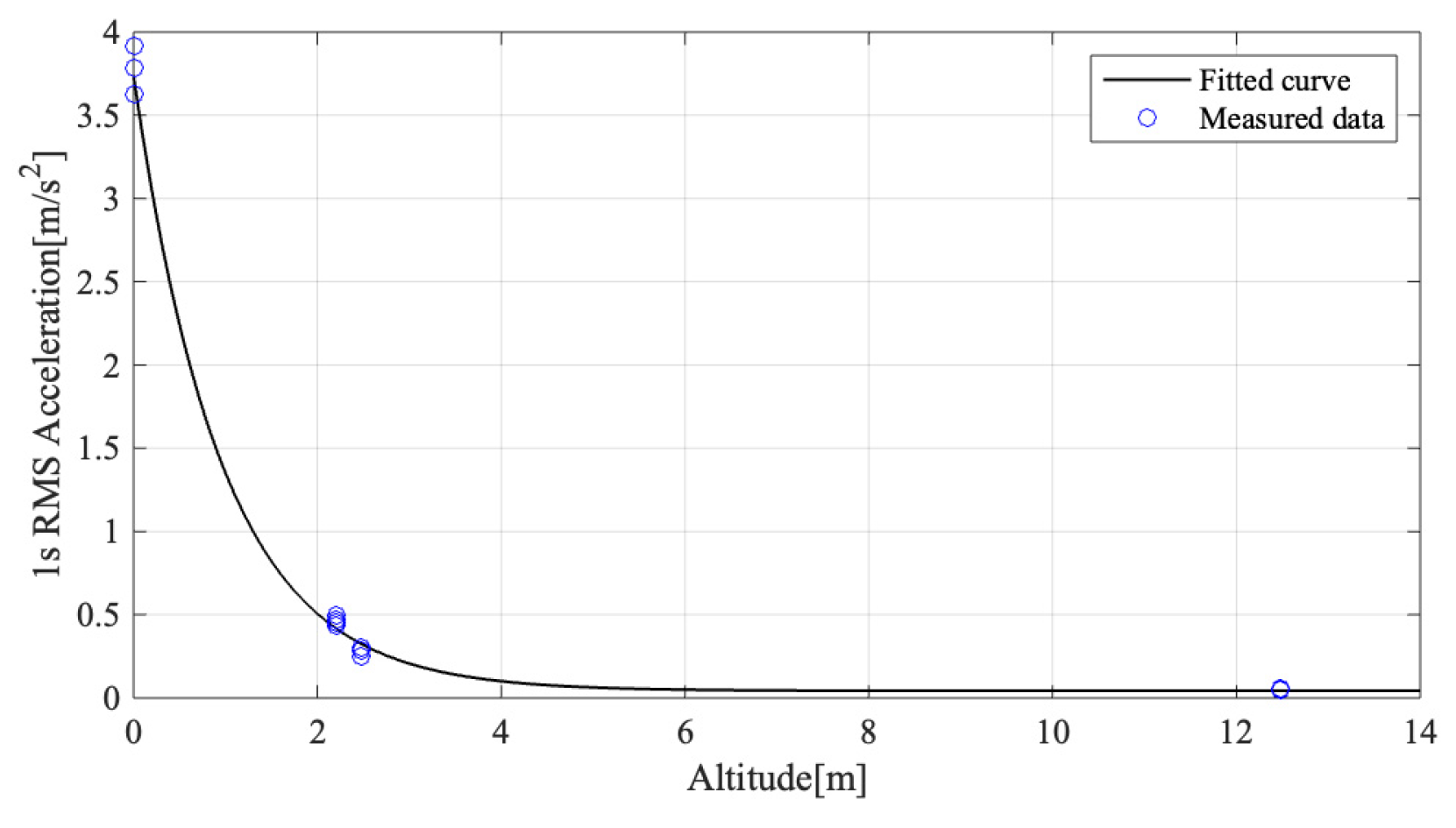
In this research, the altitude of the test point was chosen as the major affecting factor in vertical vibration propagation. Vibration records for the functional part, the upper and lower boards of the bearing, and the bottom of the column were chosen. The calculated 1s RMS values for four repetitions are shown in Table 2 (altitude indicates the distance to the test point in the functional part).
By calculating the average vibration magnitude at each altitude shown in the table above, an empirical formula can be given, as in Equation (2):
where h is the distance to the functional part; is the 1s RMS value to be calculated at a distance of h; and factor a = 3.696, b = 1.038, and c = 4.299 × 10⁻². A comparison of the measured data and the fitted curve is shown in Figure 13, and the R-square value is 0.9978.
5.2. Vibration Attenuation through Surrounding Ground
While a high-speed maglev train is running, the vibration propagated to the surrounding ground has complex distribution laws in different directions. The vibration magnitude does not monotonically decrease with increasing distance, and the maximum acceleration does not appear at the cross-sectional plane of the column. The traveling wave effects in the maglev environmental vibration problem act as the superposition and interfere with different frequency components, generating several vibration-amplifying zones in the plane. As the complex laws of vibration propagation and attenuation cannot be easily summarized using simple formulas, in this part, a visualization procedure was proposed to make it clearer.
The 1s RMS value was chosen as the evaluation of each ground test point, and the calculated results are shown in Table 3.
To visualize the propagation and attenuation laws, a three-dimensional graph of the acceleration distribution across the whole plane is given in Figure 14. The labeled dots are the measured results, and the curved surface is the biharmonic spline interpolation (through the MATLAB® 4 grid data algorithm), which makes the surface smooth and continuous, thus making it more realistic.
The 3D graph above shows the distribution of the whole plane around the maglev line. It is clear that the maximum acceleration occurs at about one-third of the distance away from the guideway column, under the maglev guideway girder, and the minimum acceleration occurs near the middle zone of the plane, where the vibration magnitude does not exceed the human perception threshold. As the distance to the maglev line increases, there is an obvious vibration-amplifying zone caused by the wave superposition, and the vibration magnitude rises with the increase in the distance. If researchers or designers estimate the ground vibration as monotone decreasing in this amplifying zone, they may underestimate the vibration level, and vibration serviceability problems may occur in structures constructed in this zone.
6. Conclusions and Discussion
6.1. Conclusions
Through the measurements and calculations carried out in this research, several conclusions can be drawn and are listed as follows:
- (1)
- The irregularity caused by bevel, offset, and dynamic deformation differences between adjacent girders has significant effects on the guideway structure vibration response, and the impact when maglev trains pass from girder to girder can reach up to 20 m/s2. Thus, it is important to control the irregularity of the maglev track.
- (2)
- The viaduct structure is helpful in reducing the vibration propagated to the ground. The peak value of acceleration at the bottom of the viaduct column usually does not exceed 0.2 m/s2. To predict the effect of column length, an empirical formula was proposed.
- (3)
- Ground vibration attenuates quickly with the increase in distance. In several zones 7.5 m away from the maglev line, the ground vibration can be lower than the human perception threshold. This phenomenon verifies that maglev transportation is suitable for use in urban transit and has the potential to be placed much closer to existing structures.
- (4)
- Like other forms of rail transportation, there also exists a vibration-amplifying zone close to the maglev line, where the ground acceleration level is much higher than in the adjacent area, with vibration magnitudes that exceed the human perception threshold. For the unique dynamic features of maglev suspension and structure characteristics, the vibration-amplifying zone is located at around the 45- to 60-degree direction, 10 m away from the maglev line.
6.2. Discussion
Due to the limits of the accelerometers, the number of test points on the guideway structure was limited; thus, empirical Equation (2) may be in potential danger of overfitting. However, as the vibration level was not too high on the top of the column, the prediction error is considered to be acceptable.
There were limitations to the area of the test site. The ground test points were mainly laid out in a 12 m 15 m area, but the results still revealed several complex laws of environmental vibration. These laws may benefit the vibration serviceability evaluation and the vibration control of structures near the maglev line, as well as the route planning of future high-speed maglev lines. Furthermore, the ground test points were set on a tarmac surface in this study, and the ground material may also influence the measurement of the vibrations, so more tests using different ground surfaces are still necessary in future research.
Author Contributions
Conceptualization, Z.H. and G.Z.; methodology, Z.H. and G.Z.; software, Z.H.; validation, Z.H., G.Z. and F.Y.; formal analysis, Z.H.; investigation, Z.H.; resources, G.Z. and F.Y.; data curation, Z.H.; writing—original draft preparation, Z.H.; writing—review and editing, G.Z.; visualization, Z.H.; supervision, G.Z.; project administration, F.Y.; funding acquisition, G.Z. All authors have read and agreed to the published version of the manuscript.
Funding
This research was funded by the National Key R&D Program of China (grant number 2016YFB1200602) and the National Natural Science Foundation of China (grant numbers 52272375 and 52232013).
Institutional Review Board Statement
Not applicable.
Informed Consent Statement
Not applicable.
Data Availability Statement
The data presented in this study are available on request from the corresponding author. The data are not publicly available due to security needs of major traffic lines.
Conflicts of Interest
The authors declare no conflicts of interest.
References
- Wu, X.; Huang, J. Guideway structure, Maglev demonstration line, Shanghai. Struct. Eng. Int. 2004, 14, 21–23. [Google Scholar] [CrossRef]
- Zhao, C.F.; Zhai, W.M. Maglev vehicle/guideway vertical random response and ride quality. Veh. Syst. Dyn. 2002, 38, 185–210. [Google Scholar] [CrossRef]
- Min, D.J.; Jung, M.R.; Kim, M.Y.; Kwark, J.W. Dynamic interaction analysis of maglev-guideway system based on a 3D full vehicle model. Int. J. Struct. Stab. Dyn. 2017, 17, 1750006. [Google Scholar] [CrossRef]
- Han, Z.P.; Chen, J. A Fuzzy Logic Vibration Control Method Based on Vibration Serviceability Criteria. In EASEC16, Proceedings of the 16th East Asian-Pacific Conference on Structural Engineering and Construction, Brisbane, Australia, 3–6 December 2019; Springer: Singapore, 2021; pp. 155–162. [Google Scholar] [CrossRef]
- Erkal, A. Transmission of Traffic-induced Vibrations on and around the Minaret of Little Hagia Sophia. Int. J. Archit. Herit. 2017, 11, 349–362. [Google Scholar] [CrossRef]
- Haladin, I.; Bogut, M.; Lakušić, S. Analysis of tram traffic-induced vibration influence on earthquake damaged buildings. Buildings 2021, 11, 590. [Google Scholar] [CrossRef]
- Weining, L.; He, X.; Wenjun, G. Study of vibration effects of underground trains on surrounding environments. Chin. J. Rock Mech. Eng. 1996, 15 (Suppl. S1), 586–593. [Google Scholar]
- Xia, H.; Wu, X.; Yu, D. Environmental vibration induced by urban rail transit system. J. North. Jiaotong Univ. 1999, 23, 1–7. [Google Scholar] [CrossRef]
- Weiming, Y.; Han, N.; Min, R. In situ experiment and analysis of environmental vibration induced by urban subway transit. Earthq. Eng. Eng. Vib. (Chin. Ed.) 2006, 26, 187. [Google Scholar] [CrossRef]
- Cui, G.H.; Tao, X.X.; Chen, X.M. Actual measurement and analysis on attenuation for environmental vibration induced by urban rail transit on ground. J. Shenyang Jianzhu Univ. (Nat. Sci.) 2008, 24, 1–39. [Google Scholar]
- Zhenxing, H.; Wanming, Z.; Zhen, L. Ground vibration caused by moving metro trains. J. Southwest Jiaotong Univ. 2008, 43, 218–221. [Google Scholar]
- Ouakka, S.; Verlinden, O.; Kouroussis, G. Railway ground vibration and mitigation measures: Benchmarking of best practices. Railw. Eng. Sci. 2022, 30, 1–22. [Google Scholar] [CrossRef]
- Gao, G.; Peng, Z.; Li, Z. Ground vibration and the influence on environment by magnetic-levitating train. Constr. Des. Proj. 2005, 4, 7–9. [Google Scholar]
- He, Y.; Wang, Y.; Zhou, L.; Gu, W. The Analysis of Environmental Impact for Maglev Vibration in Shanghai. Environ. Monit. China 2006, 3, 73–75. [Google Scholar] [CrossRef]
- Zhao, C.; Jia, X.; Zhai, W. Numerical analysis of ground vibrations of viaduct induced by high-speed maglev vehicle. J. Southwest Jiaotong Univ. 2010, 45, 825–829. [Google Scholar]
- Wen, J. Analysis of Ground Vibration Propagation Law and Influence Factors Caused by High Speed Maglev Train Operation. Master’s Thesis, Beijing Jiaotong University, Beijing, China, 2018. [Google Scholar]
- CJJT310-2021; High Speed Maglev Transportation Design Standard. Ministry of Housing and Urban-Rural Development: Beijing, China, 2021.
- ISO 2631-1:1997 (E); Mechanical Vibration and Shock: Evaluation of Human Exposure to Whole-Body Vibration. Part 1: General Requirements. ISO: Geneva, Switzerland, 1997.
- Chen, J.; Han, Z.; Xu, R. Effects of human-induced load models on tuned mass damper in reducing floor vibration. Adv. Struct. Eng. 2019, 22, 2449–2463. [Google Scholar] [CrossRef]
Figure 1.
Tested track girder and column.

Figure 2.
Track girder cross-section and test point layout.

Figure 3.
In situ accelerometer layout (all in the vertical direction).

Figure 4.
Layout diagram of ground vibration testing points.

Figure 5.
In situ accelerometer layout during the test (all in the vertical direction).

Figure 6.
Acceleration time history and frequency spectra of each test point on the guideway structure.
Figure 6.
Acceleration time history and frequency spectra of each test point on the guideway structure.

Figure 7.
Test point layout at center of maglev line.

Figure 8.
Acceleration time history and frequency spectra of each test point along the maglev line.

Figure 9.
Acceleration time history and frequency spectra of test points perpendicular to the maglev line.
Figure 9.
Acceleration time history and frequency spectra of test points perpendicular to the maglev line.

Figure 10.
Acceleration time history and frequency spectra of each test point in the 30-degree direction.
Figure 10.
Acceleration time history and frequency spectra of each test point in the 30-degree direction.

Figure 11.
Acceleration time history and frequency spectra of each test point in 45-degree direction.
Figure 11.
Acceleration time history and frequency spectra of each test point in 45-degree direction.

Figure 12.
Acceleration time history of each test point in 60-degree direction.

Figure 13.
Empirical formula of vibration propagation in the vertical direction.

Figure 14.
Vibration distribution across the plane around the maglev line.


Table 1.
Timetable of trains running throughout the test procedure.
| Number | Time | Route | Girder Number |
|---|---|---|---|
| 1 | 15:23 | Longyang–Pudong | A |
| 2 | 15:26 | Pudong–Longyang | B |
| 4 | 15:43 | Longyang–Pudong | B |
| 5 | 15:46 | Pudong–Longyang | A |
| 7 | 16:03 | Longyang–Pudong | A |
| 16:06 | Pudong–Longyang | B | |
| 8 | 16:23 | Longyang–Pudong | B |
| 16:26 | Pudong–Longyang | A | |
| 9 | 16:43 | Longyang–Pudong | A |
| 16:46 | Pudong–Longyang | B |
Table 2.
One-second RMS values of vertical test points (m/s2).
| Altitude | 0 m | 2.2 m | 2.48 m | 12.48 m |
|---|---|---|---|---|
| 1 | 3.786 | 0.435 | 0.282 | 0.053 |
| 2 | 3.912 | 0.469 | 0.304 | 0.056 |
| 2 | 3.626 | 0.455 | 0.251 | 0.048 |
| 4 | 3.630 | 0.493 | 0.255 | 0.049 |
Table 3.
One-second RMS value of each test point (mm/s2).
| Position | 0° (Along the Line) | 30° | 45° | 60° | 90° (Perpendicular to the Line) |
|---|---|---|---|---|---|
| 0 m | 45.01 | 45.01 | 61.92 | 45.01 | 45.01 |
| 7.5 m | 61.41 | 8.11 | 8.58 | 6.73 | 9.41 |
| 10 m | 68.78 | 4.31 | - | 4.77 | 5.71 |
| 12.5 m | 50.05 | 4.82 | 14.04 | 9.10 | - |
| 15 m | - | 4.87 | - | - | - |
Disclaimer/Publisher’s Note: The statements, opinions and data contained in all publications are solely those of the individual author(s) and contributor(s) and not of MDPI and/or the editor(s). MDPI and/or the editor(s) disclaim responsibility for any injury to people or property resulting from any ideas, methods, instructions or products referred to in the content. |
© 2024 by the authors. Licensee MDPI, Basel, Switzerland. This article is an open access article distributed under the terms and conditions of the Creative Commons Attribution (CC BY) license (https://creativecommons.org/licenses/by/4.0/).
Share and Cite
MDPI and ACS Style
Han, Z.; Zeng, G.; Ye, F. Research on Environmental Vibration Induced by High-Speed Maglev Transportation. Appl. Sci. 2024, 14, 413. https://doi.org/10.3390/app14010413
AMA Style
Han Z, Zeng G, Ye F. Research on Environmental Vibration Induced by High-Speed Maglev Transportation. Applied Sciences. 2024; 14(1):413. https://doi.org/10.3390/app14010413
Chicago/Turabian StyleHan, Ziping, Guofeng Zeng, and Feng Ye. 2024. "Research on Environmental Vibration Induced by High-Speed Maglev Transportation" Applied Sciences 14, no. 1: 413. https://doi.org/10.3390/app14010413
Note that from the first issue of 2016, this journal uses article numbers instead of page numbers. See further details here.