
Analytical and Experimental Investigation of the Rotary Inertia Effects of Unequal End Masses on Transverse Vibration of Beams

1
Department of Mechanical Engineering, Bolu Abant Izzet Baysal University, Golkoy Campus, Bolu 14280, Turkey
2
Institute of Natural Sciences, Sakarya University, Esentepe Campus, Serdivan 54187, Turkey
3
Department of Mechanical Engineering, Sakarya University, Serdivan 54050, Turkey
*
Author to whom correspondence should be addressed.
Appl. Sci. 2023, 13(4), 2518; https://doi.org/10.3390/app13042518
Submission received: 20 January 2023
/
Revised: 9 February 2023
/
Accepted: 11 February 2023
/
Published: 15 February 2023
(This article belongs to the Special Issue Vibration Problems in Engineering Science)
Abstract
:In this study, the transverse vibration of free–free slender beams with two unequal end masses attached were studied. The effects of the rotary inertia of the end masses on the free vibration of the beam were investigated. An exact frequency equation and the boundary conditions were obtained by using the Euler–Bernoulli beam theory and Hamilton’s principle. Natural frequencies and mode shapes of the beams in transverse vibrations were calculated for various combinations of physical and geometrical parameters, such as mass ratios, the distances between the attachment point and the center of the masses, etc. The effects of an increase in the rotational inertia of the end masses and different mass ratios on the natural frequencies and mode shapes of the beam are presented. It is shown that the increase in the rotational inertia of the end masses had a greater effect at low frequencies of the beam. In addition, experimental tests were performed to validate the obtained analytical results. A good agreement was obtained between the analytical and experimental results. The main scope of this study was to reveal the effects of the rotary inertia of the end masses on the dynamic behavior of the beam. Thus, the aim is to contribute to the understanding of the properties of the end mass and the effect of rotary inertia on the dynamics of end-mass-attached structures. Furthermore, the results obtained from this research are helpful for designing end-mass-attached structures, such as micromechanical sensors, energy harvesters, and Stockbridge-type dynamic absorbers.
1. Introduction
A vibrating beam-mass system can be found both in classic and modern engineering applications, such as micromechanical systems, atomic force microscope (AFM) probes, nanosensors, robotic manipulators, turbine blades, Stockbridge dampers, etc. In order to operate safely for these structures, it is very important to determine their dynamic characteristics during the design progress. The modeling of these structures is as close as possible to actual operating conditions; therefore, obtaining the equation of motion, solving the frequency equation, and determining the change of the natural frequencies depending on the end mass have great importance.
Many researchers have investigated free transverse vibration of beam-mass systems and a considerable amount of research outcomes have been brought together in some reference books [1,2,3,4,5,6]. The effects of rotary inertia, mass size, mass positions, springs, beam materials, etc. on the natural frequencies and mode shapes were investigated in the last decades [7,8,9,10,11,12,13,14,15]. In one of the earliest studies on beam-mass systems, Boyce and Handelman [16] studied the free transverse vibration of a Euler–Bernoulli (EB) beam with an end mass rotating at a constant speed. Craig [17] investigated the effect of the end mass on the natural frequencies and mode shapes of the beam using the modified Reissner variation theorem, by taking the beam from the work of Boyce and Handelman [16]. Öz and Özkaya [18] studied the natural frequencies of beam-mass systems in transverse vibration. They considered the Euler–Bernoulli type beam with different boundary conditions and the masses in their study were concentrated masses. They compared analytical and numerical results. Hong et al. [19] investigated the transverse vibration of the clamped–pinned–free beam with the end mass. They used the Euler–Bernoulli beam and considered the end mass as a point mass. In addition, they presented the results for varying end mass values. Langer et al. [20] studied the cantilever beam with a large tip mass. They worked numerically and experimentally and emphasized the importance of including inertia when the tip mass is large. Du et al. [21] investigated the dynamic analysis of rotating cantilever beams with a tip mass. They derived the equations of motion for free vibration analysis of the rotating cantilever beam with a tip mass by using Hamilton’s principle and a Galerkin method. Many of these studies about beam-mass systems are concerned with cantilevers, simply supported beams, and pinned beams.
Free–free beams are a special case of beams with no end restrictions. Because of these properties, they are frequently used in specific engineering applications. For instance, a free–free beam can be used in the modeling of the mechanical behavior of space structures and rockets. These engineering structures can be represented as free–free beams with one end carrying a trigger load [22,23].
A beam carrying a mass at both ends is a special class of free–free beam. Because of their importance in engineering fields, a fundamental issue is to determine the natural frequencies and mode shapes of the free–free beam with tip masses. Park and Mote [24] studied free–free beams with a concentrated mass by using the finite element method (FEM) via the extended Hamilton’s principle and their theory was based on the Euler–Bernoulli beam theory. Kirk and Wiedemann [25] obtained the natural frequencies and mode shapes of a free–free beam with large end masses connected to the beam by torsion springs. Yoon and Kim [26] investigated a spinning unconstrained beam with a concentrated mass. In their study, the beam was subjected to a thrust. Haener [27] offered an approximative formula for the first natural frequencies of the free–free beam with identical concentrated tip masses. Afterward, Erturk and Inman [28] corrected the formula presented by Haener [27], solved the problem of the free–free beam with identical concentrated end masses by using the curve fitting technique, and introduced an approximate formula for the first natural frequencies. However, their results were limited to a free–free beam with two identical tip masses. Shi et al. [29,30] presented an approximate formula for the fundamental frequency for Euler–Bernoulli and Timoshenko beams with two unequal end masses by using a Fredholm integral equation. They considered the end masses as concentrated masses.
As seen from the literature, there is little information on the natural frequencies of a free–free beam carrying unequal tip masses at both ends. On the other hand, significant progress has been made for other types of beams carrying a mass. Some new research [31,32,33,34,35] can be found on the resonance frequencies of a beam-mass structure. In most of the previous studies, the end masses were considered concentrated masses and the rotary inertia of the end masses was neglected. For example, in the study of Shi et al. [29], a free–free beam with unequal tip masses was studied; however, the masses were considered concentrated masses, so the rotational inertia of the end masses was not included in the calculations. In addition, they have proposed a new analytical formula, but there is no experimental study in their work. For this reason, in this study, in order to guide future studies, the frequencies and mode shapes of the free–free beam with unequal end masses were obtained and are presented with the inclusion of the rotary inertia of the end masses. The exact frequency equation and boundary conditions were obtained by using the Euler–Bernoulli beam theory and Hamilton’s principle. The natural frequencies of the beams were calculated, and the non-dimensional frequency parameters and mode shapes of different beam configurations are presented. In addition, experimental tests were carried out to validate the analytical results. Analytical and experimental results were in good agreement with each other.
2. The Equations of Motion and Boundary Conditions
The free–free beam with unequal end masses considered in this study is shown in Figure 1a. The masses on the left side and right side of the beam are M1 and M2, respectively. Ji represents the rotary inertia of the tip masses about the beam end. Gi represents the center of the masses and di represents the distances between the end of the beam and the center of the masses. The point B is the connection point between the end mass and the beam. The beam is homogeneous, prismatic, and has a length of L. The equation of free transverse vibration of an undamped Euler–Bernoulli beam [36] with a uniform cross-section is described by the following differential equation for small deflection:
where w(x,t) is the transverse deflection of the beam, EI is the bending stiffness of the beam, and ρA is the mass density per unit length of the beam. In Equation (1), A and I represent the cross-sectional area and the moment of inertia of the beam cross-section; respectively; x denotes the axial coordinate along the beam axis, where x = 0 is at the left end of the beam; and t represents time.
Two unequal end masses, M1 and M2 are attached to the beam at both ends. We can therefore obtain the following boundary conditions of the beam by the variational method:
at x = 0,
similarly at x = L,
For a solution of Equation (1), we can take a harmonic function as , and Equation (1) turns into:
The following non-dimensional variables are defined for simplicity in calculations:
Considering the above terms, Equation (6) is rewritten as:
with corresponding boundary conditions
at = 0,
similarly at = 1,
where the prime denotes differentiation with respect to “”.
The ordinary differential Equation (8) is solved by using a standard mathematical procedure, and its general solution can be acquired as
where is the nondimensional frequency parameter. The parameter and three of the four coefficients can be solved by applying the boundary conditions of the solution [37].
Substituting the boundary conditions in Equation (13), we obtain four algebraic equations and these equations can be written in the matrix form (Appendix A).
3. Frequency Equation
Since the equation in Appendix A has a nontrivial solution, and Ci are generally non-zero, the determinant of the coefficients matrix should be equal to zero.
Using MATLAB, with its ability to handle symbolic calculations, we obtained the frequency equation (Appendix B) of the free–free beam with tip masses, including their rotary inertias.
At this point, we took into account several cases to validate the obtained frequency equation:
Case-1: The free–free beam with two unequal concentrated tip masses. For this case, we obtain α1 = α2 = d1 = d2 = 0. So the obtained frequency equation is reduced to:
which is in precise compliance with that obtained by Shi et al. [29].
Case-2: The free–free beam with two equal concentrated tip masses. For this case, we assume M1 = M2 = M, Ω1 = Ω2 = Ω, α1 = α2 = d1 = d2 = 0. Thus, the obtained frequency equation is reduced to:
which exactly coincides with the equation obtained by Ertürk and Inman [28].
Case-3: The free–free beam with one concentrated tip mass. For this case, we obtain Ω1 = M1 = α1 = α2 = d1 = d2 = 0, M2 ≠ 0. Thus, the obtained frequency equation is reduced to:
Case-4: The free–free beam with no tip masses. For this case, we obtain Ω1 = Ω2 = α1 = α2 = d1 = d2 = 0, so the obtained frequency equation is turned into the well-known cantilever beam frequency equation:
The frequency equation obtained in this study is also valid for cases where the position of the gravity center of the end mass is ξ < 1, as seen in Figure 1b. This would facilitate the designer during the positioning of the end mass in the design of a tip-mass-attached structure, such as an energy harvester or dynamic vibration absorber. In cases where the gravity center position of the end mass increases such that ξ > 1, namely when the G2 point is shifted along the +x direction, the end mass will adversely affect the dynamic behavior of the beam. In this case, the beam may behave as a stepped beam. If the gravity center of the end mass is shifted to be ξ < 1 as seen in Figure 1b, the end mass will not negatively affect the beam dynamics and will also offer convenience to the designer in terms of construction.
4. Results
Numerical results are given to show the accuracy of the obtained frequency equation and the effects of the tip masses and rotary inertias of the masses on the natural frequencies and mode shapes of the beam.
4.1. Natural Frequencies
Figure 1 shows that a great variety of values for Mi, Ji, and di, are possible. In this section, we show how we calculated the nondimensional frequency parameter for the first five natural frequencies for different end masses and rotary inertias. The acquired numerical results are listed in Table 1 and Table 2.
The values of the nondimensional frequency parameter obtained from the frequency equation for some standard cases in the literature are shown in Table 1, and these values were the same as the corresponding precise frequency equations of free–free, free–clamped, free–pinned, pinned–pinned, clamped–clamped, and clamped–pinned beams [6].
The case of corresponds to a free–free beam with no tip mass; the case of , the beam behavior as a pinned–pinned beam. Additionally, corresponds to a clamped–clamped beam, while or corresponds to a clamped–free or a free–clamped beam, respectively. Additionally, a vibrating beam-mass system with or represents a free–pinned beam or pinned–free beam. In order to represent infinity, a sufficiently large number should be chosen. We arrived at in place of to represent infinity and to make it possible for numerical computation.
The first five nondimensional frequency parameters were computed by solving the characteristic equation. As can be seen from Table 2, an increase in or decreased the frequency values as expected. In addition, while the value was constant, the increase in the rotary inertia of tip masses decreased the natural frequency values. Provided that the mass of the end mass remained constant, an increase in the rotary inertia should result in an increase in the distance between the end-mass center of gravity and the beam attachment point. In this case, the thickness of the end mass should decrease. Since the rotational inertia is directly related to the value, this shows that increasing the value of decreases the natural frequencies of the beam.
As can be seen from Figure 2, the change in the first two dimensionless frequency parameters was higher than the others. It is seen that the change in the upper frequencies was much less. It is seen that there was no change in the fourth and fifth frequency parameters when the value approached 1. As a result, it can be said that the increase in the rotational inertia of the end masses was more effective, especially at low frequencies of the structure.
4.2. Modal Shape Functions
After solving the frequency equation, the nondimensional frequency parameter could be easily obtained. Using these parameters, we could calculate the corresponding mode shapes. Setting C1 = 1 in the equation (Appendix A) and obtaining the other coefficients in terms of C1, we could obtain the mode shape equation (Appendix C).
Using the obtained nondimensional frequency parameters , the mode shapes Wi could be determined, which are related to . As can be seen from Figure 2, the increase in the rotational inertia of the end masses affected the first two frequency parameters more. Increasing the value did not cause a significant change in the third, fourth, and fifth mode shapes. For this reason, the first and second modes of the beam with end mass are plotted depending on the change in and the change in the mode shapes of the beam due to the increase in the rotational inertia of the end mass is shown.
The first and second mode shapes of a free–free beam with tip masses for some different combinations of and can be seen in Figure 3 and Figure 4. Figure 3a,b show the changes in the first and second mode shapes of a clamped–free beam with unequal end masses depending on the changes of . Although there is a significant change in the first mode shape with the change in values, it is seen that the mode shapes converge towards other with the increase in values in the second mode shape.
Figure 4a,b show the changes in the first and second mode shapes of a free–free beam due to the changes in . It is seen that the changes in the mode shapes of the free–free beam due to the changes in are less than that of the clamped–free beam.
5. Experimental Verification
5.1. Experimental Setup
In this section, the experimental setup shown in Figure 5a was prepared to verify the natural frequencies obtained analytically. The beam with different masses at both ends was suspended from each end by an inextensible rope to ensure the free–free boundary condition. The physical parameters related to beam and end masses used in the experimental study are given in Table 3.
The first five natural frequencies of free–free beams with different end masses were obtained by using the standard modal analysis method [38]. In this method, the structure is impacted with an impact hammer and the response of the structure is obtained by means of an accelerometer. In order to obtain the response of the structure under the standards, the structure is divided into certain points, and an impact is applied to these points with the impact hammer. For this reason, in our study, nine points were marked on the beam. The equipment used in the experimental study is shown in Figure 5c. A single-axis DYTRAN accelerometer with 101.25 mV/g sensitivity was used to obtain the acceleration data precisely. The accelerometer was mounted on the heavier mass so that the vibration data would not be affected by the weight of the accelerometer. A Brüel & Kjær impact hammer with a sensitivity of 2.24 mV/N was used to impact the beam with tip masses. The accelerometer and impact hammer were connected to a Brüel & Kjær Photon+ model data analyzer. The beam was divided into nine points and acceleration data from the beam-end mass system were obtained by applying an impact to these points on the beam with the impact hammer. Inappropriate impacts were eliminated using software and not included in the average. The fast Fourier transform (FFT) analysis of the obtained vibration data was performed using RT Pro Photon data analysis software. The tests were similarly repeated 10 times and the natural frequencies of the beam-end mass system were obtained by taking the average of these tests.
5.2. Experimental Results and Comparison with Analytical Results
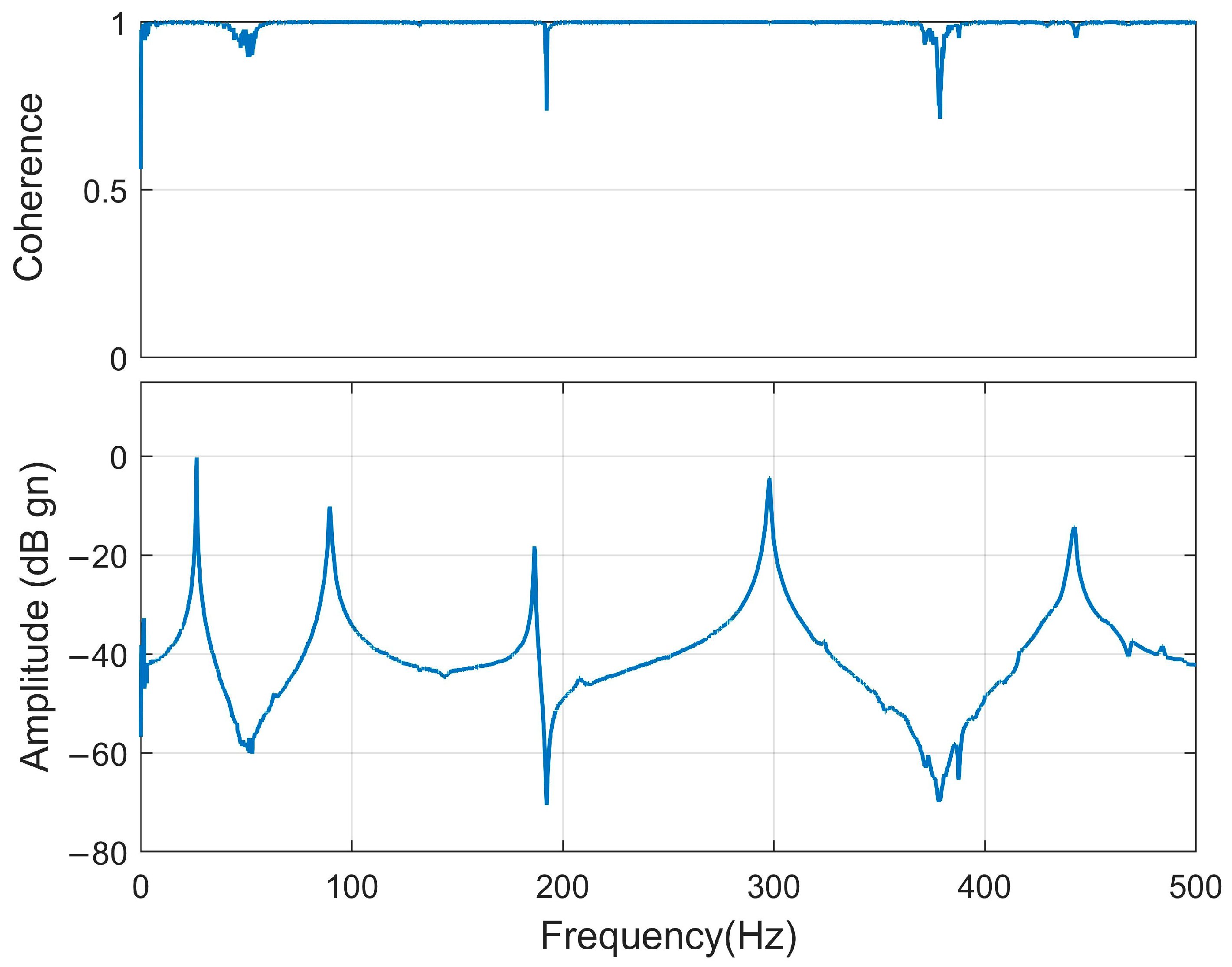
The coherence function and the frequency–amplitude graph obtained as a result of the modal analysis are shown in Figure 6; the graph was obtained by taking the average of the experimental data. The peaks in the frequency–amplitude graph show the natural frequency values of the system. The frequency resolution was set to 0.125 Hz to obtain the acceleration data precisely. The measurements were repeated by applying an impact to the points on the beam with the impact hammer. Thus, a precise measurement of the natural frequencies of the beam was performed. A coherence function value of 1 means that there was no noise in the measurement. The coherence values of the obtained frequency values were very close to 1, indicating that the measurements were not affected by noise.
The first five natural frequencies of the beam-end mass system obtained by experimental modal analysis and analytical method are given in Table 4 comparatively. It is seen that the biggest difference between analytical and experimental natural frequencies was 1.86%. This difference becomes smaller at higher frequencies. Experimental results and analytical results do not fully agree with each other due to undesirable disruptive effects, such as air friction, environmental noise, etc. in the experimental study. For this reason, in scientific studies, this difference can be accepted up to 15% depending on the difficulty of the experimental study. In this study, the highest difference was 1.86%. This shows that the frequency equation obtained analytically represents as well as possible the real operating conditions of the free–free beam with unequal end masses.
6. Conclusions
In this study, we investigated the transverse vibration of a free–free beam with unequal end masses and obtained an exact frequency equation. In this equation, the rotary inertia of the end masses was also taken into account. The first five natural frequencies and mode shapes of the beam were obtained. The influences of tip masses and rotary inertias on the natural frequencies and mode shapes were presented by obtaining the analytical results of the frequency equation. In order to verify the natural frequency values obtained analytically, an experimental study was carried out and the first five natural frequencies of the free–free beam with unequal end masses were obtained. Some of the results obtained from this study and the main novelties and contributions of this paper can be summarized:
- The natural frequencies and mode shapes of the free–free beam with unequal end masses were obtained by including the rotary inertia of the end masses.
- The first five nondimensional frequency parameters were obtained and presented in a table for different values of .
- The first and second mode shapes of the free–free beam with unequal end masses were obtained for different values of .
- It was concluded that the increase in the rotational inertia of the end mass was more effective at low frequencies and mode shapes of the structure.
- The increase in the distance between the gravity center of the end mass and the beam connection point decreases the beam’s natural frequencies.
- Experimental testing was performed to verify the frequency equation. The results obtained were in good agreement with analytical results. Due to undesirable interference effects in the experimental study, the difference between the experimental results and the analytical results could be accepted by up to 15%. In our study, the highest difference was 1.86%. This showed that the frequency equation obtained analytically represented the real operating conditions as well as possible.
The results obtained from this research are helpful for designing engineering structures, such as energy harvesters and Stockbridge-type dynamic vibration absorbers. Moreover, when designing Stockbridge dampers or dynamic vibration absorbers, our results will be helpful in determining tip masses, the distances between the gravity center of the end mass and the beam connection point, and tip/beam mass ratios.
Taking advantage of this work, the distance d2 can be increased in the x-axis to obtain suitable frequency and mode shapes in the dynamic absorber design. However, since this may cause some difficulties in terms of structural design, the position of G2 can also be designed in cases when ξ < 1, as shown in Figure 1b. This means that the end mass center of gravity is also slidable to the left of the attachment point B. This will afford convenience to the designer in terms of construction.
Author Contributions
Conceptualization, H.B. and Ö.K.M.; Methodology, H.B. and Ö.K.M.; Software, H.B.; Validation, H.B. and Ö.K.M.; Formal analysis, H.B. and Ö.K.M.; Investigation, H.B. and Ö.K.M.; Resources, H.B.; Data curation, H.B. and Ö.K.M.; Writing—original draft, H.B. and Ö.K.M.; Visualization, H.B. All authors have read and agreed to the published version of the manuscript.
Funding
This research received no external funding.
Institutional Review Board Statement
Not applicable.
Informed Consent Statement
Not applicable.
Data Availability Statement
The data used in this study are available from the corresponding author upon request.
Acknowledgments
The authors would also like to thank Sakarya University for supplying technological and experimental support.
Conflicts of Interest
The authors declare no conflict of interest.
Appendix A
The equations in matrix form are obtained by substituting the boundary conditions in Equation (13):
where
Appendix B
Frequency equation for a free–free beam with unequal tip masses including their rotary inertias:
Appendix C
Modal shape function of the free–free beam with tip masses:
where
References
- Meirovitch, L. Analytical Methods in Vibrations; Macmillian Company: New York, NY, USA, 1967. [Google Scholar]
- Blevins, R.D. Formulas for Natural Frequency and Mode Shape; Van Nostrand Reinhold: New York, NY, USA, 1979. [Google Scholar]
- Pilkey, W. Formulas for Stress, Strain, and Structural Matrices; John Wiley & Sons: Hoboken, NJ, USA, 2005. [Google Scholar]
- Karnovsky, I.; Lebed, O.; Karnovskii, I. Free Vibrations of Beams and Frames; McGraw-Hill Professional Publishing: New York, NY, USA, 2004. [Google Scholar]
- Wang, C.; Wang, C. Structural Vibration: Exact Solutions for Strings, Membranes, Beams, and Plates; CRC Press: Boca Raton, FL, USA, 2013. [Google Scholar]
- Rao, S.S. Mechanical Vibrations, 6th ed.; Prentice Hall: Hoboken, NJ, USA, 2018. [Google Scholar]
- Srinath, L.S.; Das, Y.C. Vibrations of Beams Carrying Mass. J. Appl. Mech. Trans. ASME 1964, 34, 784–785. [Google Scholar] [CrossRef]
- Lau, J.H. Fundamental Frequency of a Constrained Beam. J. Sound Vib. 1981, 78, 154–157. [Google Scholar] [CrossRef]
- Gürgöze, M. A Note on the Vibrations of Restrained Beams and Rods with Point Masses. J. Sound Vib. 1984, 96, 461–468. [Google Scholar] [CrossRef]
- Laura, P.A.A.; Cortinez, V.H. Optimization of Eigenvalues in the Case of Vibrating Beams with Point Masses. J. Sound Vib. 1986, 108, 346–347. [Google Scholar] [CrossRef]
- Oguamanam, D.C.D. Free Vibration of Beams with Finite Mass Rigid Tip Load and Flexural-Torsional Coupling. Int. J. Mech. Sci. 2003, 45, 963–979. [Google Scholar] [CrossRef]
- Wu, J.S.; Hsu, T.F. Free Vibration Analyses of Simply Supported Beams Carrying Multiple Point Masses and Spring-Mass Systems with Mass of Each Helical Spring Considered. Int. J. Mech. Sci. 2007, 49, 834–852. [Google Scholar] [CrossRef]
- Jafarzadeh Jazi, A.; Shahriari, B.; Torabi, K. Exact Closed Form Solution for the Analysis of the Transverse Vibration Mode of a Nano-Timoshenko Beam with Multiple Concentrated Masses. Int. J. Mech. Sci. 2017, 131–132, 728–743. [Google Scholar] [CrossRef]
- Mahmoud, M.A. Natural Frequency of Axially Functionally Graded, Tapered Cantilever Beams with Tip Masses. Eng. Struct. 2019, 187, 34–42. [Google Scholar] [CrossRef]
- Dal, H.; Baklaci, M. Design, Fabrication and Vibration Analysis of a Lightweight Head Expander for a High Frequency Electrodynamic Shaker. Mater. Test. 2019, 61, 965–972. [Google Scholar] [CrossRef]
- Boyce, W.E.; Handelman, G.H. Vibrations of Rotating Beams with Tip Mass. Zeitschrift Angew. Math. Phys. ZAMP 1961, 12, 369–392. [Google Scholar] [CrossRef]
- Craig, R.R. Rotating Beam with Tip Mass Analyzed by a Variational Method. J. Acoust. Soc. Am. 1963, 35, 990–993. [Google Scholar] [CrossRef]
- Öz, H.R.; Özkaya, E. Natural Frequencies of Beam-Mass Systems in Transverse Motion for Different End Conditions. Math. Comput. Appl. 2005, 10, 369–376. [Google Scholar] [CrossRef] [Green Version]
- Hong, J.; Dodson, J.; Laflamme, S.; Downey, A. Transverse Vibration of Clamped-Pinned-Free Beam with Mass at Free End. Appl. Sci. 2 2019, 9, 2996. [Google Scholar] [CrossRef] [Green Version]
- Langer, P.; Jelich, C.; Guist, C.; Peplow, A.; Marburg, S. Simplification of Complex Structural Dynamic Models: A Case Study Related to a Cantilever Beam and a Large Mass Attachment. Appl. Sci. 2021, 11, 5428. [Google Scholar] [CrossRef]
- Du, X.; Zhang, J.; Guo, X.; Li, L.; Zhang, D. Dynamics Analysis of Rotating Cantilever Beams with Free End Mass. Appl. Sci. 2022, 12, 7553. [Google Scholar] [CrossRef]
- Beal, T.R. Dynamic Stability of a Flexible Missile under Constant and Pulsating Thrusts. AIAA J. 1965, 3, 486–494. [Google Scholar] [CrossRef]
- Kavianipour, O.; Khoshnood, A.M.; Irani, S.; Roshanian, J. Reduction of the Actuator Oscillations in a Free-Free Jointed Bipartite Beam Model under a Follower Force. Aerosp. Sci. Technol. 2012, 22, 45–57. [Google Scholar] [CrossRef]
- Park, Y.P.; Mote, C.D. The Maximum Controlled Follower Force on a Free-Free Beam Carrying a Concentrated Mass. J. Sound Vib. 1985, 98, 247–256. [Google Scholar] [CrossRef]
- Kirk, C.L.; Wiedemann, S.M. Natural Frequencies and Mode Shapes of a Free-Free Beam with Large End Masses. J. Sound Vib. 2002, 254, 939–949. [Google Scholar] [CrossRef]
- Yoon, S.J.; Kim, J.H. A Concentrated Mass on the Spinning Unconstrained Beam Subjected to a Thrust. J. Sound Vib. 2002, 254, 621–634. [Google Scholar] [CrossRef]
- Haener, J. Formulas for the Frequencies Including Higher Frequencies of Uniform Cantilever and Free-Free Beams With Additional Masses at the Ends. J. Appl. Mech. 1958, 25, 412. [Google Scholar] [CrossRef]
- Erturk, A.; Inman, D.J. On the Fundamental Transverse Vibration Frequency of a Free-Free Thin Beam with Identical End Masses. J. Vib. Acoust. Trans. ASME 2007, 129, 656–662. [Google Scholar] [CrossRef]
- Shi, W.; Li, X.F.; Lee, K.Y. Transverse Vibration of Free-Free Beams Carrying Two Unequal End Masses. Int. J. Mech. Sci. 2015, 90, 251–257. [Google Scholar] [CrossRef]
- Shi, W.; Shen, Z.B.; Peng, X.L.; Li, X.F. Frequency Equation and Resonant Frequencies of Free–Free Timoshenko Beams with Unequal End Masses. Int. J. Mech. Sci. 2016, 115–116, 406–415. [Google Scholar] [CrossRef]
- Khalili, S.M.R.; Damanpack, A.R.; Nemati, N.; Malekzadeh, K. Free Vibration Analysis of Sandwich Beam Carrying Sprung Masses. Int. J. Mech. Sci. 2010, 52, 1620–1633. [Google Scholar] [CrossRef]
- Banerjee, J.R. Free Vibration of Beams Carrying Spring-Mass Systems—A Dynamic Stiffness Approach. Comput. Struct. 2012, 104–105, 21–26. [Google Scholar] [CrossRef]
- Wang, D. Frequency Sensitivity Analysis for Beams Carrying Lumped Masses with Translational and Rotary Inertias (IJMS-11890). Int. J. Mech. Sci. 2012, 65, 192–202. [Google Scholar] [CrossRef]
- Kalsoom, A.; Shankar, A.N.; Kakaravada, I.; Jindal, P.; Lakshmi, V.V.K.; Rajeshkumar, S. Investigation of Dynamic Properties of a Three-Dimensional Printed Thermoplastic Composite Beam Containing Controllable Core under Non-Uniform Magnetic Fields. Proc. Inst. Mech. Eng. Part L J. Mater. Des. Appl. 2021, 236, 404–412. [Google Scholar] [CrossRef]
- Mahmoud, M.A. Free Vibrations of Tapered and Stepped, Axially Functionally Graded Beams with Any Number of Attached Masses. Eng. Struct. 2022, 267, 114696. [Google Scholar] [CrossRef]
- Timoshenko, S.; Young, D. Vibration Problems in Engineering; Wiley: New York, NY, USA, 1974. [Google Scholar]
- To, C.W.S. Vibration of a Cantilever Beam with a Base Excitation and Tip Mass. J. Sound Vib. 1982, 83, 445–460. [Google Scholar] [CrossRef]
- Harris, C.M.; Piersol, A.G. Harris’ Shock and Vibration Handbook, 5th ed.; McGraw-Hill Professional: New York, NY, USA, 2002; p. 1568. [Google Scholar]
Figure 1.
(a) The free–free beam with unequal end masses; (b) an alternative attachment of the end mass that has its gravity center point at ξ < 1.
Figure 1.
(a) The free–free beam with unequal end masses; (b) an alternative attachment of the end mass that has its gravity center point at ξ < 1.

Figure 2.
Variation of frequency parameter () depending on the inertia parameter ().
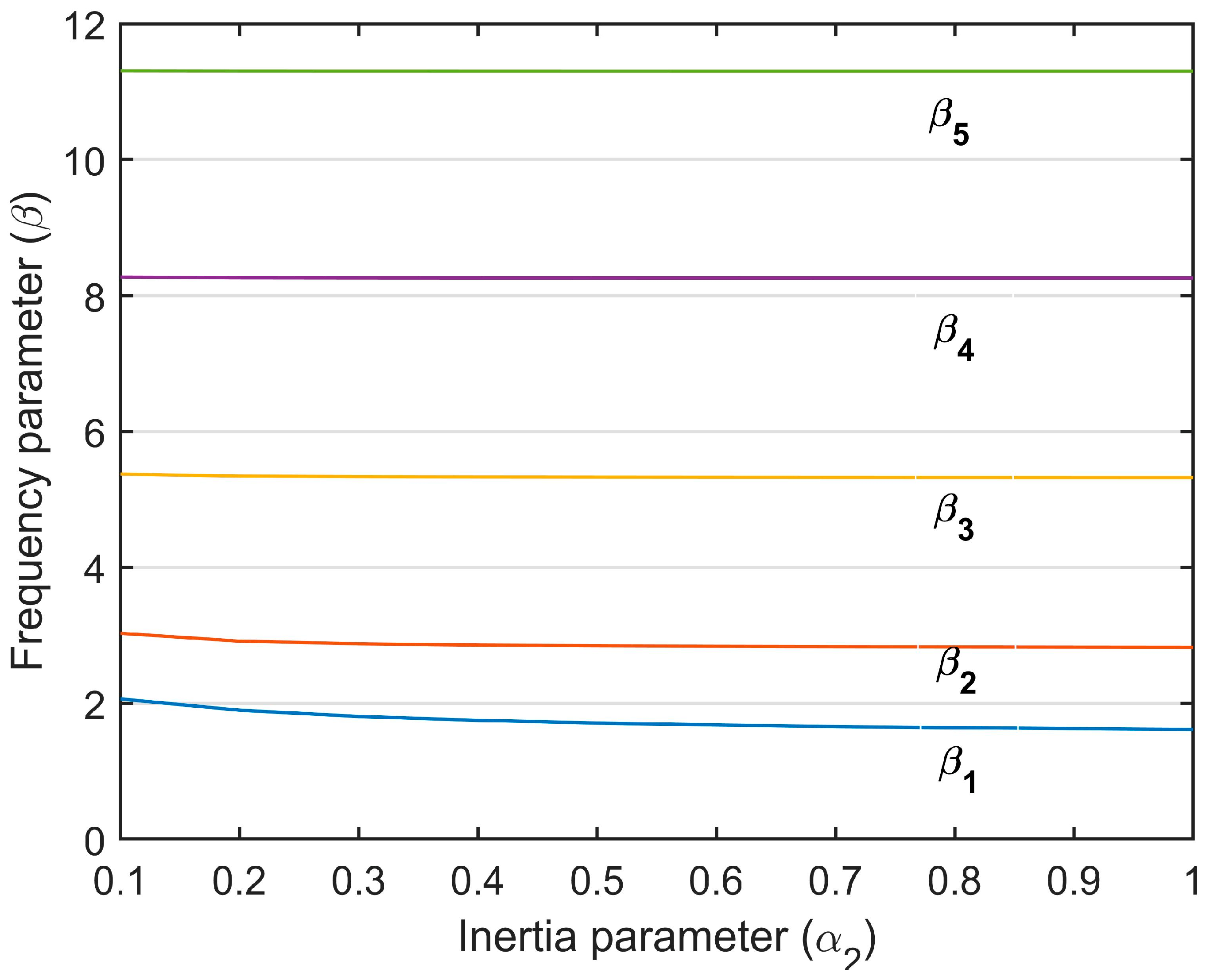
Figure 3.
First and second mode shapes of the clamped–free beam with various values: (a) first mode shape, (b) second mode shape.
Figure 3.
First and second mode shapes of the clamped–free beam with various values: (a) first mode shape, (b) second mode shape.
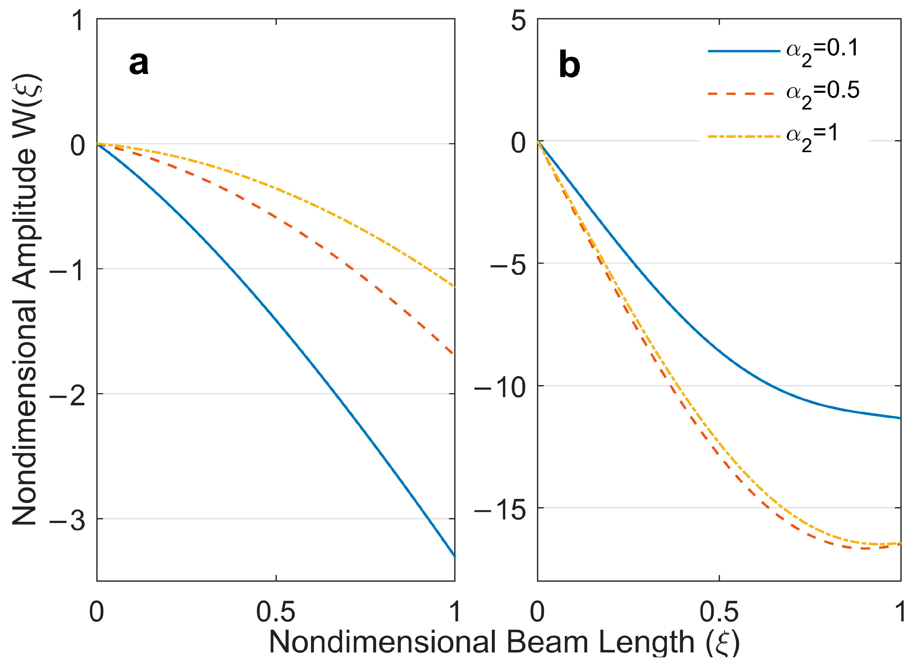
Figure 4.
First and second mode shapes of the free–free beam with various values: (a) first mode shape, (b) second mode shape.
Figure 4.
First and second mode shapes of the free–free beam with various values: (a) first mode shape, (b) second mode shape.
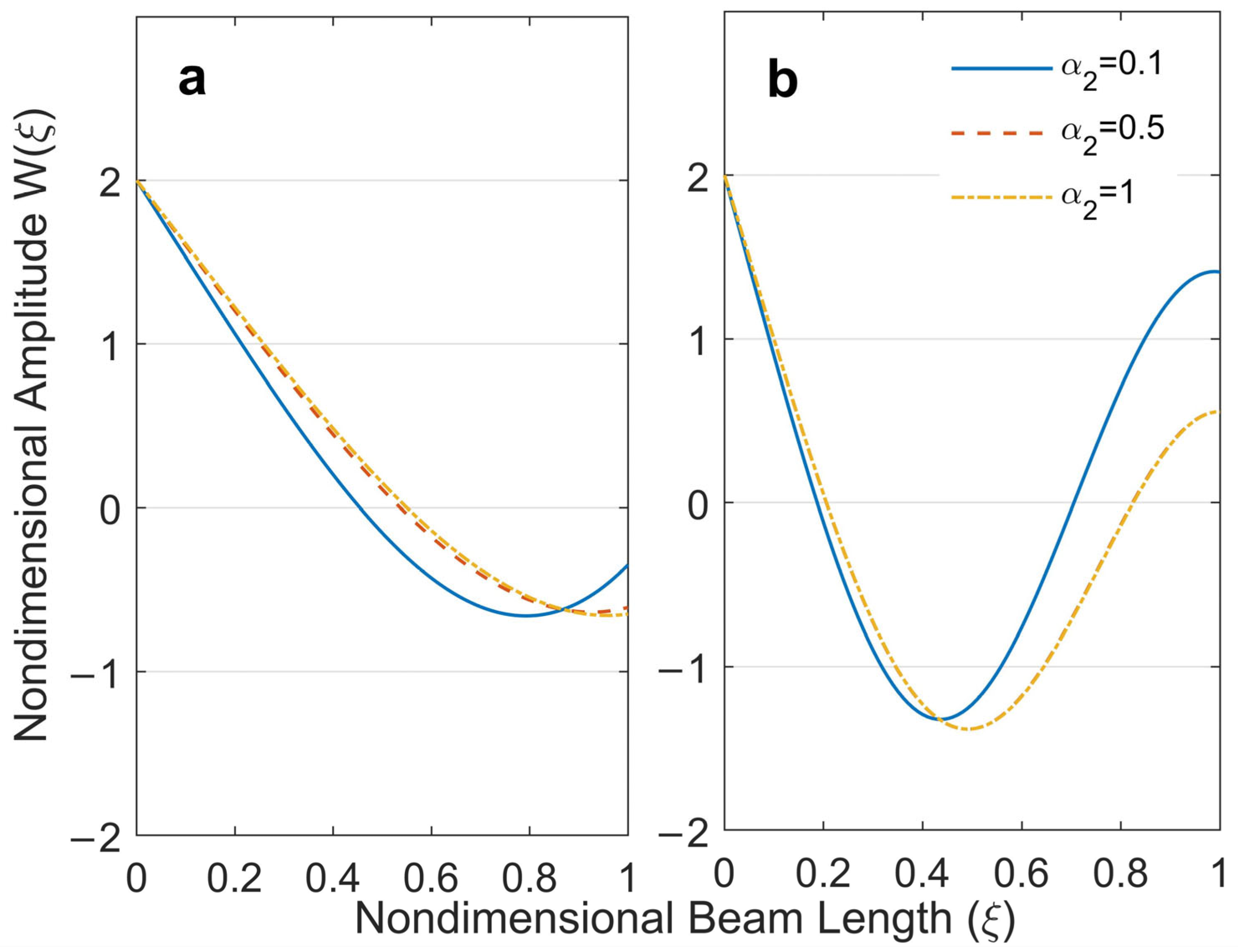
Figure 5.
(a) Free–free beam with unequal end masses, (b) 3D section view of the beam and notations of dimensions (M2), (c) data acquisition system: (1) computer including RT Pro Photon data analysis software; (2) impact hammer; (3) photon+ data acquisition card.
Figure 5.
(a) Free–free beam with unequal end masses, (b) 3D section view of the beam and notations of dimensions (M2), (c) data acquisition system: (1) computer including RT Pro Photon data analysis software; (2) impact hammer; (3) photon+ data acquisition card.

Figure 6.
Coherence function and frequency–amplitude graph of the free–free beam with unequal tip masses.
Figure 6.
Coherence function and frequency–amplitude graph of the free–free beam with unequal tip masses.

Table 1.
The obtained first five nondimensional frequency parameters for standard cases.
| Nondimensional Frequency Parameters | |||||||||
|---|---|---|---|---|---|---|---|---|---|
| 0 | 0 | 0 | 0 | Present study | 4.7300 | 7.8532 | 10.9956 | 14.1372 | 17.2788 |
| Reference [6] | 4.730041 | 7.853205 | 10.995608 | 14.137165 | -- | ||||
| 0 | 0 | Present study | 1.8751 | 4.6941 | 7.8548 | 10.9955 | 14.1372 | ||
| Reference [6] | 1.875104 | 4.694091 | 7.854757 | 10.995541 | -- | ||||
| 0 | 0 | Present study | 3.1416 | 6.2832 | 9.4248 | 12.5664 | 15.7080 | ||
| Reference [6] | 3.141592 | 6.283185 | 9.424777 | 12.566370 | -- | ||||
| Present study | 4.7300 | 7.8532 | 10.9956 | 14.1372 | 17.2788 | ||||
| Reference [6] | 4.730041 | 7.853205 | 10.995608 | 14.137165 | -- | ||||
| 0 | 0 | 0 | Present study | 3.9266 | 7.0686 | 10.2102 | 13.3518 | 16.4934 | |
| Reference [6] | 3.926602 | 7.068583 | 10.210176 | 13.351768 | -- | ||||
| 0 | Present study | 3.9266 | 7.0686 | 10.2102 | 13.3518 | 16.4934 | |||
| Reference [6] | 3.926602 | 7.068583 | 10.210176 | 13.351768 | -- | ||||
Table 2.
The first five nondimensional frequency parameters for different values of .
| Nondimensional Frequency Parameters | ||||||||
|---|---|---|---|---|---|---|---|---|
| 0.5 | 0.1 | 0.5 | 0.01 | 2.3587 | 3.9918 | 5.8927 | 8.4328 | 11.3698 |
| 0.1 | 2.0652 | 3.0312 | 5.3734 | 8.2727 | 11.3075 | |||
| 1 | 1.6155 | 2.8248 | 5.3220 | 8.2578 | 11.3016 | |||
| 0.5 | 1 | 0.5 | 0.01 | 1.8035 | 3.9030 | 5.8626 | 8.4196 | 11.3640 |
| 0.1 | 1.6155 | 2.8248 | 5.3220 | 8.2578 | 11.3016 | |||
| 1 | 1.1863 | 2.4757 | 5.2674 | 8.2428 | 11.2956 | |||
| 0.5 | 0.1 | 1 | 0.01 | 2.3046 | 3.9818 | 5.8622 | 8.3642 | 11.3060 |
| 0.1 | 2.0594 | 2.9811 | 5.2816 | 8.1918 | 11.2410 | |||
| 1 | 1.5960 | 2.7360 | 5.2241 | 8.1759 | 11.2348 | |||
| 0.5 | 1 | 1 | 0.01 | 1.7069 | 3.8892 | 5.8327 | 8.3506 | 11.3001 |
| 0.1 | 1.5689 | 2.7814 | 5.2273 | 8.1763 | 11.2349 | |||
| 1 | 1.1859 | 2.3570 | 5.1659 | 8.1603 | 11.2286 | |||
Table 3.
The physical properties of beam and tip masses.
| Properties | Beam | Tip Mass (M1) | Tip Mass (M2) |
|---|---|---|---|
| Modulus of elasticity, E (GPa) | 210 | 210 | 210 |
| Density, ρ (kg/m3) | 7800 | 7800 | 7800 |
| Length, L or LM, (mm) | 323.5 | 25.555 | 15.35 |
| Width, w (mm) | 30 | 30 | 30 |
| Thickness, tb or tM, (mm) | 1.185 | 21.185 | 21.185 |
| Mass, Mb or Mtip, (gr) | 87.520 | 126.660 | 76.090 |
| Distances, d, (mm) | - | 12.777 | 7.675 |
| Rotary inertia (according to the attachment point), Jz, (kg.m2) | - | 32.30 × 10⁻⁶ | 8.822 × 10⁻⁶ |
Table 4.
The first five natural frequencies of the beam-end mass system.
| Natural Frequencies | Analytical (Hz) | Experimental (Hz) | Error (%) |
|---|---|---|---|
| 1st | 30.086 | 29.68 | 1.35 |
| 2nd | 100.012 | 98.15 | 1.86 |
| 3rd | 191.337 | 188.6 | 1.43 |
| 4th | 293.348 | 298 | −1.59 |
| 5th | 437.994 | 442 | −0.91 |
Disclaimer/Publisher’s Note: The statements, opinions and data contained in all publications are solely those of the individual author(s) and contributor(s) and not of MDPI and/or the editor(s). MDPI and/or the editor(s) disclaim responsibility for any injury to people or property resulting from any ideas, methods, instructions or products referred to in the content. |
© 2023 by the authors. Licensee MDPI, Basel, Switzerland. This article is an open access article distributed under the terms and conditions of the Creative Commons Attribution (CC BY) license (https://creativecommons.org/licenses/by/4.0/).
Share and Cite
MDPI and ACS Style
Bilge, H.; Morgül, Ö.K. Analytical and Experimental Investigation of the Rotary Inertia Effects of Unequal End Masses on Transverse Vibration of Beams. Appl. Sci. 2023, 13, 2518. https://doi.org/10.3390/app13042518
AMA Style
Bilge H, Morgül ÖK. Analytical and Experimental Investigation of the Rotary Inertia Effects of Unequal End Masses on Transverse Vibration of Beams. Applied Sciences. 2023; 13(4):2518. https://doi.org/10.3390/app13042518
Chicago/Turabian StyleBilge, Habibullah, and Ömer Kadir Morgül. 2023. "Analytical and Experimental Investigation of the Rotary Inertia Effects of Unequal End Masses on Transverse Vibration of Beams" Applied Sciences 13, no. 4: 2518. https://doi.org/10.3390/app13042518
Note that from the first issue of 2016, this journal uses article numbers instead of page numbers. See further details here.