Article

Investigation of Vibration Characteristics during Various Building Construction Stages under Train Operations

1
School of Civil and Transportation Engineering, Guangdong University of Technology, Guangzhou 510006, China
2
China Academy of Railway Science (Shenzhen) Research and Design Institute Co., Ltd., Shenzhen 518052, China
3
Guangzhou Urban Planning & Design Survey Research Institute Co., Ltd., Guangzhou 510060, China
4
School of Civil Engineering and Architecture, Wuhan Polytechnic University, Wuhan 430023, China
5
College of Automotive Engineering, Jilin University, Changchun 130015, China
*
Author to whom correspondence should be addressed.
Appl. Sci. 2024, 14(6), 2283; https://doi.org/10.3390/app14062283
Submission received: 31 January 2024 / Revised: 1 March 2024 / Accepted: 6 March 2024 / Published: 8 March 2024

Abstract

:
In response to land use challenges, major urban centers have started implementing over-track building constructions above metro lines as a means of accommodating residents and workers. However, the continuous operation of trains can generate excessive vibrations that may negatively impact the overall living conditions for occupants residing in these structures. In this paper, vibration measurements were conducted on the soil and within a three-story frame structure building. Additionally, a three-dimensional finite element model of the track–soil–building was established. The wheel–rail contact force was incorporated as a dynamic load that varies with time to accurately simulate the vibration response induced by trains. According to the construction process of the over-track building, four construction stages were set up using the finite element model to study the impact of the construction stages on the vibration propagation from the soil to building structure. The results indicate that the presence of existing structures exerts a mitigating influence on soil vibrations. Pile foundation construction can effectively mitigate soil vibration to a significant extent. The findings provide references for the future development and design of over-track buildings.

1. Introduction

The urban rail transit system possesses numerous advantages, including its high transport capacity, ability to alleviate traffic congestion and pollution, speed and efficiency, reliability, as well as comfort and safety. These attributes render it an indispensable component of contemporary urban transportation planning. The development of urban rail transit has been progressing rapidly and plays a pivotal role in contributing to the socio-economic landscape. To address the issue of urban land scarcity and provide financial support for metro operations, an increasing number of over-track buildings are being constructed above metro lines.
However, train operations can result in noticeable vibrations for individuals residing or working in buildings located above the tracks, leading to discomfort and potential adverse effects on human health [1,2]. Therefore, comprehending and assessing the impact of train-induced vibrations on these buildings is crucial for implementing necessary mitigation measures.
Two highly accurate methods for assessing the impact of train-induced vibrations on buildings are available: on-site measurements and numerical modeling. Regarding on-site measurements, previous studies have been conducted to investigate the characteristics of indoor vibrations in buildings located along rail transit lines [3,4,5,6]. Additionally, scholars have performed on-site vibration measurements at metro depots with over-track buildings to examine the effects of train-induced vibrations and conduct comprehensive analyses regarding the internal transmission laws within these structures [7,8,9,10]. Furthermore, some researchers have also carried out on-site vibration measurements focusing on soil–structure interaction in adjacent or over-track buildings [11]. Numerical modeling has been employed by scholars to accurately predict the vibration effects of rail traffic on adjacent or over-track buildings, with some establishing a train track–soil–building model [12,13,14], while others have conducted dynamic interaction studies of vehicle–track–bridge–soil [15,16,17,18,19,20] to investigate the behavior of rail bridges and soil–structure effects. Some scholars have taken into account the soil–structure interaction effect to investigate the dynamic interplay between soil inclusion and soil properties [21,22]. Some scholars have also taken into account the soil–structure interaction effect to investigate the impact of the vibration induced by train operation on adjacent or over-track buildings [23,24,25,26].
There are relatively few studies on the propagation of vibrations in buildings above tracks caused by train operation in different construction stages [27,28,29,30]. By investigating the impact of the surface foundation on ground vibration during the construction phase, Auersch et al. [27] examined the response of flexible plates made of homogeneous or layered soil to horizontal propagation waves in terms of distance and frequency. Edirisinghe et al. [28] analyzed the lateral and vertical pile loading effects, as well as the influence of the pile length, to study the dynamic source–receiver interaction between an underground railway tunnel and a pile foundation during the construction stage. Anvarsamarin et al. [29] investigated the impact of construction activities on the vibration characteristics of building foundations during the construction phase and proposed a simplified model for analyzing the influence of additional structures. Sanitate et al. [30] studied the variation in ground vibration levels during the construction phase, with the progress of construction, and analyzed the effects of additional foundations and additional buildings on the attenuation or amplification of ground vibration levels caused by buildings through coupling loss. In summary, a plethora of field measurements are available on the vibration caused by train operation on adjacent or over-track buildings and related soil–structure interaction. However, numerical simulation studies primarily focus on the impact of train operation on the internal vibration of adjacent or over-track buildings and the dynamic interaction between trains, rails, bridges, and soil. There have been relatively few investigations into the vibration transmission during different over-track building construction stages caused by train operations.
This study involves conducting on-site vibration measurements of both the soil and columns in close proximity to the track, as well as within the interior of the over-track building. Subsequently, a three-dimensional finite element model of the track–soil–building system was established using the finite element method, with validation performed against the measured data. Finally, this three-dimensional finite element model was utilized to investigate vibration transmission laws from the soil to building structure during various stages of over-track building construction.

2. Measurements

The measurement site was selected in the train operation area beneath a three-story column frame building, which is constructed on a platform that is 9 m above the tracks and supported by structural columns (as illustrated in Figure 1).

2.1. Instruments

The instrumentation employed for measurement is illustrated in Figure 2, comprising a JM3873 wireless data acquisition system (Figure 2a) and 941B accelerometers (Figure 2b).
Prior to conducting field measurements, all wireless units were time synchronized through a laptop connected to a wireless gateway placed side-by-side. Subsequently, the wireless units were left operational to ensure synchronization among them and securely mounted at their respective measurement locations. The potential concerns regarding interference and blockage issues were mitigated during the measurement process by avoiding the transmission of internally sampled/stored time signals. Subsequently, upon completion of the measurements, the time-synchronized data were retrieved from each wireless unit.
The wireless units were configured with a sampling frequency of 512 Hz, enabling spectral analysis up to the Nyquist frequency of 256 Hz. It should be noted that the dominant frequency range of train-induced floor vibration in this study was found to be below 80 Hz. More details about the measuring instruments and signal processing can be found in the reference [7].

2.2. Setup

The arrangement of the measurement setups within the designated measurement area is illustrated in Figure 3. The platform has a width of 53 m and a length of 110 m, with the latter dimension aligned in the direction of train travel. Below it are three tracks spaced at intervals of 5 m from each other, each positioned at a distance of 3.3 m from the nearest structural column.
As depicted in Figure 3b, the train operation area is situated beneath the platform, with an accelerometer, G1, positioned adjacent to the nearest structural column on the soil. Simultaneously, an accelerometer, C1, was affixed to the structural column at a height of 0.5 m above ground level. This arrangement aims to investigate vibration propagation laws and responses between soil and building columns. As illustrated in Figure 3c, an accelerometer, C2, was strategically placed on the first floor of the over-track building, approximately 8.3 m away from track #2.
According to the functional issues pertaining to structural members and similar site selection problems discussed in reference [7], as well as the actual site and building layout constraints, this study selects C1, C2, and G1 for analysis. The chosen locations enable the examination of the dynamic interaction and inertial interaction between the soil and structure [28].

2.3. Results

A total of 13 trains traveling on track #2 in the morning were recorded during the measurements. The running train consists of a six-unit B-type car, measuring approximately 120 m in length and traveling at an average speed of 13 km/h. The train speed ranges from 10.48 to 15.91 km/h, while the time taken for the train to pass through the measuring point falls between 27.15 and 41.22 s.
The time histories and spectrogram of soil G1, ground column C1, and first floor C2 are shown in Figure 4. The peak vertical acceleration measured adjacent to column G1 is approximately 0.2 m/s2, while the peak vertical acceleration recorded on column C1 amounts to around 0.02 m/s2. Additionally, on the first floor of the over-track building, the peak vertical acceleration measured at the bottom of column C2 reaches approximately 0.011 m/s2. The vertical vibration amplitude of G1 is significantly larger compared to C1 and C2, indicating a pronounced attenuation during the transfer from the soil to the column.
Meanwhile, the spectrogram reveals that G1 exhibits predominant energy concentration within the frequency range of 20–80 Hz, whereas C1 and C2 predominantly exhibit an energy concentration within the frequency band of 20–40 Hz. The present observation implies a substantial attenuation of high-frequency components above 40 Hz during both the soil-to-column transition and over-track building processes.
Figure 5 shows that the vertical vibration response of both the soil and columns during train operation exhibits a close resemblance within the frequency range of 12.5–31.5 Hz. The soil vibration resulting from train operation reaches its peak at 63 Hz, followed by a subsequent decrease in the vibration level within the high-frequency range. The transmission of vibration waves from G1 to C1 and C2 exhibits a significant amplification effect at 10 Hz, which is attributed to the resonance induced by the newly formed natural frequency between the building structure and the soil. The vertical vibrations attenuate in the medium- and high-frequency range above 40 Hz due to the dynamic interaction between the structure and soil, dependent on their contact area and respective characteristics. The former exhibits a typical resonance between the building and soil, while the latter is attributed to the interaction between the soil and structure. The vibration response of the measurements will serve as a means for validating the finite element model. The measurement results can be compared with relevant national normative indicators [31] to assess their impact on the building and evaluate whether the vibrations exceed permissible limits, potentially affecting human occupants.

3. Numerical Model and Validation

A numerical model is proposed that integrates a train track dynamic model with a track–soil–building finite element model to accurately predict building vibrations. This comprehensive model effectively simulates the motion of a six-vehicle metro train on the track and has been validated through measurements.

3.1. Train Track Dynamic Model

The dynamic response of the train track dynamic model can be solved by train track coupled dynamic theory [32,33], in which a train consists of a series of vehicles, and each vehicle consists of a total of 10 degrees of freedom, as shown in Figure 6. The car body and bogies are only considered vertical displacement w c , w t 1 , w t 2 , and rotation θ c , θ t 1 , θ t 2 , respectively, and the wheelsets are considered vertical displacement w w 1 , w w 2 , w w 3 , w w 4 . The train mathematical model is established based on the aforementioned content and subsequently integrated with the established track mathematical model into a system through specific contact relationships to obtain dynamic responses.
The vertical wheel–rail contact force F v / r is defined with a nonlinear Hertz contact relationship [34], in which the Hertz contact introduces the non-uniform distribution of the wheel–rail contact force, thereby accounting for wear, fatigue, and deformation in the actual contact area, resulting in more accurate simulation results. F v / r can be defined as
F v / r = 1 G q v q r h 3 2 q v q r h 0 0 q v q r h < 0
where q v and q r represent the vertical displacement of the contact point between the wheel and track, respectively. The variable h represents the vertical irregularity amplitude of the rail, while G represents the wheel–rail contact constant.
The equations of motion for the train track dynamic model can be denoted as
M q ¨ + C q ˙ + K q = F
where M, C, and K denote global mass, damping, and stiffness matrices of the assembled train track dynamic model, respectively, and specific parameters of the train and track structure can be referred to in Li et al. [24]; q, q ˙ , q ¨ denote the displacement, velocity, and acceleration vectors of the whole model, respectively. The input to the load vector F is provided by the wheel–rail contact force.
To solve the equation of motion for the train track dynamic model, the Wilson-θ method is used. The calculation mainly considers the effect of vertical track profile irregularity. The American track spectrum of sixth grade and the Sato irregularity spectrum [24,32] are adopted. The wheel–rail contact force is shown in Figure 7.

3.2. Track–Soil–Building Finite Element Model

As shown in Figure 8, the numerical model consists of the track structure, foundation soil, and over-track building. All materials were modeled using a linear elastic principal model. The floor slabs, walls, and platform were assumed to be conventional shell elements (S4R). The structural columns and beams were constructed using two-node linear beam elements (B31). The foundation soil dimensions were 110 m × 170 m × 70 m (X × Y × Z) and were constructed using hexahedral solid units (C3D8R). The track structure consists of rails, fasteners, sleepers, and ballasts, and the fasteners were modeled using spring-damping units, while the rest of the track structure was constructed using hexahedral solid units (C3D8R). To address the interference caused by vibration wave reflection at the far field boundary, which can lead to energy superposition and result in inaccuracies, an infinite element approach was employed to simulate this boundary issue within the soil domain. The absorbing boundary was constructed using a three-dimensional solid eight-node infinite unit (CIN3D8).
The specific structural parameters of the over-track building as well as the pile foundation are shown in Table 1. For detailed information regarding the soil properties in each layer, please refer to Table 2.
The track structure was situated at ground level, with a three-story building erected above it. The soil was represented in distinct layers, exhibiting a damping ratio of 0.03. Both the dimensions and parameters of the building and track structure strictly adhere to realistic values. Under small strain conditions, the soil and pile demonstrate reasonable elastic properties; however, their dynamic behavior exhibits strong coupling. Therefore, an embedded regional constraint was incorporated into the pile–soil interaction model to accurately describe their contact behavior.
The minimum element size was set to be less than one-sixth of the minimum shear wavelength of the soil of interest in order to ensure accurate calculations for frequencies below 80 Hz [35]. The upper surface of the rails should specifically bear the wheel–rail force, with an element size set to 0.025 m. The appropriate element size for the surface soil is determined as 0.285 m. Considering the train load on the surface and computational speed requirements, the distribution of the soil elements transitions from dense to sparse as the depth increases. For over-track buildings and pile foundations, a uniform grid cell size of 0.5 m was employed. The full-scale track–soil–building finite element model comprises a total of 3,742,568 elements and 3,990,731 nodes.

3.3. Model Validation

Figure 9 and Figure 10 show the calculated vertical vibration acceleration on the soil and the first floor at 8.3 m from the track, which were compared with the measured vertical vibration at the same locations. The time domain amplitudes of the vibration response obtained from the established finite element model exhibit a close resemblance to the measured values. The simulation results demonstrate a more concentrated manifestation of train-induced vibrations, with less pronounced peak acceleration, possibly attributed to random variations in track unevenness and inherent soil layer heterogeneity.
Figure 11 shows the comparison of the measured and simulated acceleration levels on the soil and the first floor. The simulated acceleration levels across the entire frequency range of 4–80 Hz exhibit consistency with the overall trend observed in the measured data, with the peak frequencies of vibration acceleration all occurring at the same frequencies. However, it should be noted that the simulated acceleration levels across all the frequency bands are lower than those obtained from measurements. This discrepancy may potentially arise due to uncertainties associated with track irregularities and the simplification of soil layers, among other factors.

4. Vibration Characteristics during Various Building Construction Stages

The propagation of vibration in an unobstructed environment (free field) is influenced by the inherent material characteristics of the soil, thereby affecting its amplitude. However, when encountering structural interference, the path of vibration wave propagation undergoes alterations leading to wave reflection and bypass. In this section, the construction process of the over-track building is divided into four stages: site preparation, pile foundation construction, platform construction, and building construction, as shown in Figure 12. The observation points for soil, piles, and structural columns are incorporated into the finite element model.

4.1. Soil Vibrations

The vertical acceleration levels of the soil at distances of 8.3 m, 17.3 m, and 26.3 m from track #2 under various construction stages are depicted in Figure 13. The vibration responses induced by train operations in both the pile construction and free field exhibit similar trends. However, the vibrations in the free field significantly surpass those observed in the pile construction, particularly at the measurement points located far from the vibration source. This phenomenon can be attributed to the dominance of Rayleigh waves in far-field vibrations, with a substantial dissipation of energy from body waves, indicating that the structure effectively suppresses soil vibrations. Furthermore, this phenomenon can also be partially ascribed to the implementation of the pile foundation, which introduces an additional mechanism for the dissipation of energy.
Within a distance of 26.3 m from the source, both the pile construction and free field exhibit a dominant frequency response of 50 Hz for soil vibration. The platform construction and building construction also demonstrate consistent near-field behavior with a peak frequency of 63 Hz, attributed to the emergence of novel characteristic frequencies within the soil–structure system. As the measurement point moves to the far field at 17.3 m, the peak frequency decreases to 50 Hz. This phenomenon can be attributed to the dissipation of body wave energy as the distance from the source increases, leading to the dominance of Rayleigh waves and consequent attenuation of high-frequency components. The order of soil vibration amplitudes is as follows: free field, pile construction, building construction, and platform construction. The impact of soil vibration is directly proportional to the mass and stiffness of a building. Buildings with higher masses and greater stiffness will induce stronger reactions when vibrating in a non-free field, resulting in amplified soil vibration compared to platform construction.

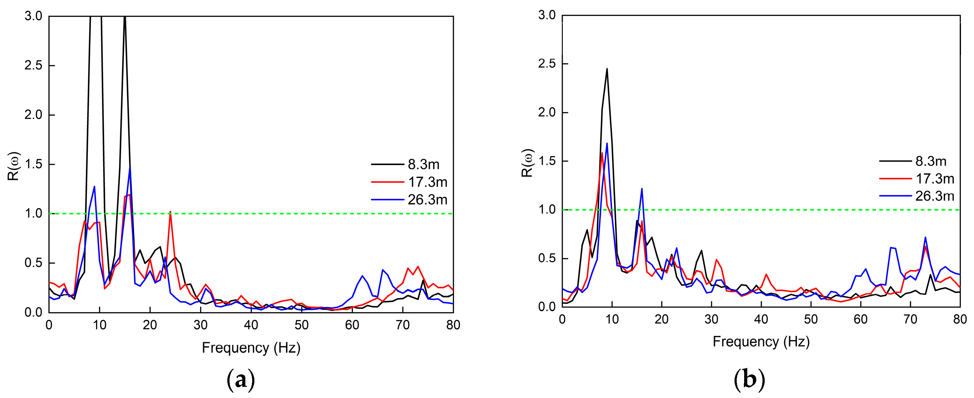
4.2. Transfer Function of Soil and Pile Foundation

To investigate the vibration characteristics during various stages of construction, the transfer function R(ω) is used to represent the coupling loss between the soil of the free field and structure, which can be denoted as
R ( ω ) = A ( ω ) A 0 ( ω )
where A(ω) and A0(ω) are the vertical vibration accelerations of the structures and soil in the frequency domain, respectively.
Figure 14 shows the vibration transfer function of the soil and pile when the simulated train operates on track #2. These observed locations are equipped with group pile foundations, characterized by a depth of 1 m, a pile length of 53 m, a pile diameter of 0.8 m, and an inter-pile spacing of 9 m in the direction perpendicular to the track. The presence of the structures is observed to moderately dampen vibrations and induce kinematic effects when compared to the free field soil, with attenuation generally increasing as the frequency rises.
The transmission of soil vibration to the pile resulted in an amplification effect within the frequency range of 8–15 Hz, particularly evident at a distance of 8.3 m from the source at the building construction, exhibiting a clear inertia effect. This phenomenon can be attributed to the formation of a novel soil–structure integrated system during pile foundation construction and subsequent stages, characterized by a resonant frequency within the range of 8–15 Hz, resulting in enhanced vibration amplification within this frequency band. In the frequency range of 20–50 Hz, the transfer coefficient exhibits a decreasing trend with increasing distance from the vibration source. This can be attributed to the dominance of surface waves in the far field, while body waves play a relatively minor role, and there is a weakened interaction between body waves and piles within the soil. The transfer coefficient in the 50–80 Hz frequency range at the far field surpasses that observed near the vibration source under all the construction stages, which was attributed to the decrease in the effective interaction area between the soil and the structure with increasing distance, resulting in a decrease in the structure’s suppression of vibration, especially in some high-frequency bands. This implies that the presence of the building plays a significant role in attenuating high-frequency vibration propagation.
Hence, the construction of pile foundations effectively mitigates soil vibration to a significant extent, with a minimal impact on the transfer function of soil and piles compared to platform construction and building construction. After the completion of pile foundation construction, the timely measurement of pile vibration acceleration can be conducted. By utilizing the measured vibration acceleration as input for the building model, the calculation of the building vibration response becomes feasible, thereby enabling prompt adjustments to be made to the building’s vibration reduction measures.

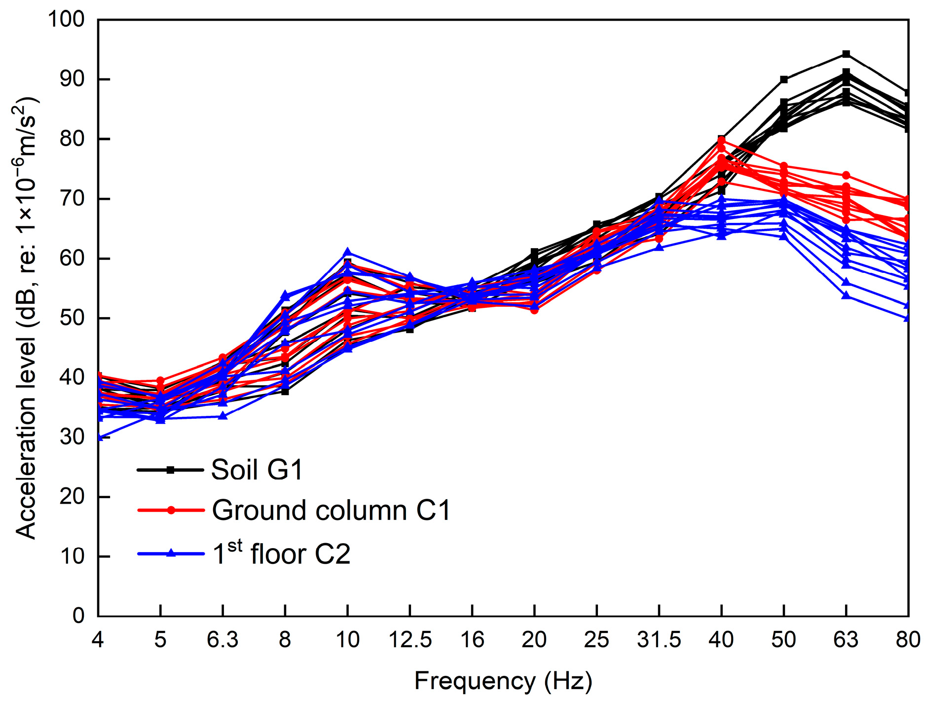
4.3. Transfer Function of Soil and Column

Figure 15 shows the vibration transfer coefficient between the soil in the free field and the column in the construction stages of platform construction and building construction. The column vibrations in close proximity to the vibration source at 10 Hz exhibit amplification compared to the soil in the unobstructed field, with a higher transfer coefficient observed for platform construction as opposed to building construction at this specific frequency. In the frequency band above 20 Hz, the vibration energy coupling loss generated by the platform construction is larger than that of the building construction.

5. Conclusions

In this study, vibration measurements were conducted on buildings adjacent to and on the track to validate the developed finite element model. The model was subsequently employed to predict vehicle-induced vibration responses under various operational conditions, thereby elucidating vibration variations during different construction stages and discussing relevant foundation effects and building effects induced by soil–structure interaction. The following main conclusions were drawn:
(1)
Soil vibrations induced by train operations exhibit greater magnitudes during the site preparation stage in the free field compared to other construction phases, suggesting that existing structures have a mitigating effect on soil vibrations.
(2)
Pile foundation construction can effectively mitigate soil vibration to a significant extent; the transfer function of the soil and pile is minimally affected by the construction of pile foundations in comparison to the construction of platforms and buildings.
(3)
In the range of 50–80 Hz, higher soil–structure transfer coefficients in the far field compared to those near the vibration source indicate buildings attenuate high-frequency vibrations.
(4)
During platform construction, there is a more pronounced resonance effect between the buildings and soil at 10 Hz. The coupling loss of vibration energy from the platform construction is higher than that from the building construction above 20 Hz.
These findings contribute to a deeper comprehension of the influence exerted by foundations and building structures on the propagation of ground vibrations, thereby offering valuable insights for designers in determining the optimal location and layout of building structures, as well as serving as a reference for implementing measures aimed at reducing vibrations.

Author Contributions

Conceptualization, C.Z.; methodology, J.H. and C.Z.; validation, J.H., C.Z. and Y.C.; investigation, J.H., Y.C., L.H., J.W., C.L. and Z.L.; resources, L.H., J.W., C.L. and Z.L.; data curation, J.H., C.Z. and Y.C.; writing—original draft preparation, J.H.; writing—review and editing, C.Z., Y.C. and Z.T.; visualization, L.H.; project administration, C.Z. and Z.T.; funding acquisition, C.Z. All authors have read and agreed to the published version of the manuscript.

Funding

This research was funded by the National Natural Science Foundation of China, grant number 51908139.

Institutional Review Board Statement

Not applicable.

Informed Consent Statement

Not applicable.

Data Availability Statement

The raw data supporting the conclusions of this article will be made available by the authors on request.

Acknowledgments

The authors would like to give thanks to Zixiong Shen and Junhuan Wu for collaborating on the vibration measurements.

Conflicts of Interest

Author Ying Chen was employed by the company China Academy of Railway Science (Shenzhen) Research and Design Institute Co., Ltd. Author Lingshan He was employed by the company Guangzhou Urban Planning & Design Survey Research Institute Co., Ltd. The remaining authors declare that the re-search was conducted in the absence of any commercial or financial relationships that could be construed as a potential conflict of interest.

References

  1. Kowalska-Koczwara, A. Influence of Location of Measurement Point on Evaluation of Human Perception of Vibration. J. Meas. Eng. 2019, 7, 147–154. [Google Scholar] [CrossRef]
  2. Kowalska-Koczwara, A. Impact of Selected Sources of Transport Vibrations on the Perception of Vibrations by People in Buildings. Vibroengineering Procedia 2019, 27, 88–92. [Google Scholar] [CrossRef]
  3. Anderson, D.C. Engineering Prediction of Railway Vibration Transmitted in Buildings. Environ. Eng. 1994, 7, 14–16, 18–19. [Google Scholar]
  4. Heckl, M.; Hauck, G.; Wettschureck, R. Structure-borne sound and vibration from rail traffic. J. Sound Vib. 1996, 193, 175–184. [Google Scholar] [CrossRef]
  5. Gladwell, G.M.L.; Zimmermann, G. On Energy and Complementary Energy Formulations of Acoustic and Structural Vibration Problems. J. Sound Vib. 1966, 3, 233–241. [Google Scholar] [CrossRef]
  6. He, W.; Cui, H.; Yang, S. Estimation of Structural Dynamic Response Induced by Individual Sit-to-Stand Loading Using Acceleration Response Spectrum Approach. Mech. Syst. Signal Process. 2024, 211, 111233. [Google Scholar] [CrossRef]
  7. Tao, Z.; Wang, Y.; Sanayei, M.; Moore, J.A.; Zou, C. Experimental Study of Train-Induced Vibration in over-Track Buildings in a Metro Depot. Eng. Struct. 2019, 198, 109473. [Google Scholar] [CrossRef]
  8. Zou, C.; Moore, J.A.; Sanayei, M.; Tao, Z.; Wang, Y. Impedance Model of Train-Induced Vibration Transmission Across a Transfer Structure into an Overtrack Building in a Metro Depot. J. Struct. Eng. 2022, 148, 04022187. [Google Scholar] [CrossRef]
  9. Cao, Z.; Guo, T.; Zhang, Z.; Li, A. Measurement and Analysis of Vibrations in a Residential Building Constructed on an Elevated Metro Depot. Measurement 2018, 125, 394–405. [Google Scholar] [CrossRef]
  10. Guo, T.; Cao, Z.; Zhang, Z.; Li, A. Numerical Simulation of Floor Vibrations of a Metro Depot under Moving Subway Trains. J. Vib. Control 2017, 24, 4353–4366. [Google Scholar] [CrossRef]
  11. Colaço, A.; Alves Costa, P.; Castanheira-Pinto, A.; Amado-Mendes, P.; Calçada, R. Experimental Validation of a Simplified Soil-Structure Interaction Approach for the Prediction of Vibrations in Buildings Due to Railway Traffic. Soil Dyn. Earthq. Eng. 2021, 141, 106499. [Google Scholar] [CrossRef]
  12. Qiu, Y.; Zou, C.; Hu, J.; Chen, J. Prediction and mitigation of building vibrations caused by train operations on concrete floors. Appl. Acoust. 2024, 219, 109941. [Google Scholar] [CrossRef]
  13. Ma, M.; Xu, L.; Liu, W.; Tan, X. Semi-Analytical Solution of a Coupled Tunnel-Soil Periodic Model with a Track Slab under a Moving Train Load. Appl. Math. Model. 2024, 128, 588–608. [Google Scholar] [CrossRef]
  14. Lopes, P.; Costa, P.A.; Ferraz, M.; Calçada, R.; Cardoso, A.S. Numerical Modeling of Vibrations Induced by Railway Traffic in Tunnels: From the Source to the Nearby Buildings. Soil Dyn. Earthq. Eng. 2014, 61–62, 269–285. [Google Scholar] [CrossRef]
  15. Liu, Q.; Li, X.; Zhang, X.; Zhou, Y.; Chen, Y.F. Applying Constrained Layer Damping to Reduce Vibration and Noise from a Steel-Concrete Composite Bridge: An Experimental and Numerical Investigation. J. Sandw. Struct. Mater. 2018, 22, 1743–1769. [Google Scholar] [CrossRef]
  16. Liu, Q.; Thompson, D.J.; Xu, P.; Feng, Q.; Li, X. Investigation of Train-Induced Vibration and Noise from a Steel-Concrete Composite Railway Bridge Using a Hybrid Finite Element-Statistical Energy Analysis Method. J. Sound Vib. 2020, 471, 115197. [Google Scholar] [CrossRef]
  17. Martínez-De la Concha, A.; Cifuentes, H.; Medina, F. A Finite Element Methodology to Study Soil–Structure Interaction in High-Speed Railway Bridges. J. Comput. Nonlinear Dyn. 2018, 13, 031010. [Google Scholar] [CrossRef]
  18. De Roeck, G.; Degrande, G.; Lombaert, G.; Müller, G. 3D Numerical Analysis of Train-induced Vibrations on Short Bridges Considering Vehicle-Track-Structure-Soil Dynamic Interaction. In Proceedings of the 8th International Conference on Structural Dynamics, EURODYN 2011, Leuven, Belgium, 4–6 July 2011. [Google Scholar]
  19. Bhure, H.; Sidh, G.; Gharad, A. Dynamic Analysis of Metro Rail Bridge Subjected to Moving Loads Considering Soil–Structure Interaction. Int. J. Adv. Struct. Eng. 2018, 10, 285–294. [Google Scholar] [CrossRef]
  20. Heiland, T.; Aji, H.D.B.; Wuttke, F.; Stempniewski, L.; Stark, A. Influence of Soil-Structure Interaction on the Dynamic Characteristics of Railroad Frame Bridges. Soil Dyn. Earthq. Eng. 2023, 167, 107800. [Google Scholar] [CrossRef]
  21. He, C.; Zhou, S.; Guo, P. Mitigation of Railway-Induced Vibrations by Using Periodic Wave Impeding Barriers. Appl. Math. Model. 2022, 105, 496–513. [Google Scholar] [CrossRef]
  22. Li, H.; He, C.; Gong, Q.; Zhou, S.; Li, X.; Zou, C. TLM-CFSPML for 3D Dynamic Responses of a Layered Transversely Isotropic Half-Space. Comput. Geotech. 2024, 168, 106131. [Google Scholar] [CrossRef]
  23. He, L.; Tao, Z. Building Vibration Measurement and Prediction during Train Operations. Buildings 2024, 14, 142. [Google Scholar] [CrossRef]
  24. Li, X.; Chen, Y.; Zou, C.; Chen, Y. Train-Induced Vibration Mitigation Based on Foundation Improvement. J. Build. Eng. 2023, 76, 107106. [Google Scholar] [CrossRef]
  25. Lopes, P.; Alves Costa, P.; Calçada, R.; Silva Cardoso, A. Influence of Soil Stiffness on Building Vibrations Due to Railway Traffic in Tunnels: Numerical Study. Comput. Geotech. 2014, 61, 277–291. [Google Scholar] [CrossRef]
  26. Khan, B.L.; Farooq, H.; Usman, M.; Butt, F.; Khan, A.Q.; Hanif, A. Effect of Soil–Structure Interaction on a Masonry Structure under Train-Induced Vibrations. Proc. Inst. Civ. Eng.—Struct. Build. 2019, 172, 922–934. [Google Scholar] [CrossRef]
  27. Auersch, L. Response to Harmonic Wave Excitation of Finite or Infinite Elastic Plates on a Homogeneous or Layered Half-Space. Comput. Geotech. 2013, 51, 50–59. [Google Scholar] [CrossRef]
  28. Edirisinghe, T.L.; Talbot, J.P. The Significance of Source-Receiver Interaction in the Response of Piled Foundations to Ground-Borne Vibration from Underground Railways. J. Sound Vib. 2021, 506, 116178. [Google Scholar] [CrossRef]
  29. Anvarsamarin, A.; Rofooei, F.R.; Nekooei, M. Soil-Structure Interaction Effect on Fragility Curve of 3D Models of Concrete Moment-Resisting Buildings. Shock Vib. 2018, 2018, 7270137. [Google Scholar] [CrossRef]
  30. Sanitate, G.; Talbot, J.P. Foundation Vibration and the Added-Building Effect: Experimental Evidence from a Ground-Borne Vibration Measurement Campaign. J. Sound Vib. 2023, 544, 117390. [Google Scholar] [CrossRef]
  31. ISO 2631-1; Mechanical Vibration and Shock—Evaluation of Human Exposure to Whole-Body Vibration—Part 1: General Requirements. ISO: Geneva Switzerland, 1997.
  32. Sato, Y. Study on High-Frequency Vibrations in Track Operated with High-Speed Trains. In Railway Technical Research Institute, Quarterly Reports; Railway Technical Research Institute: Tokyo, Japan, 1977; 18(Rpt No. 1013-76). [Google Scholar]
  33. Zhai, W.; Wang, K.; Cai, C. Fundamentals of Vehicle–Track Coupled Dynamics. Veh. Syst. Dyn. 2009, 47, 1349–1376. [Google Scholar] [CrossRef]
  34. Wu, T.X.; Thompson, D.J. Wheel/Rail Non-Linear Interactions with Coupling between Vertical and Lateral Directions. Veh. Syst. Dyn. 2004, 41, 27–49. [Google Scholar] [CrossRef]
  35. López-Mendoza, D.; Connolly, D.P.; Romero, A.; Kouroussis, G.; Galvín, P. A Transfer Function Method to Predict Building Vibration and Its Application to Railway Defects. Constr. Build. Mater. 2020, 232, 117217. [Google Scholar] [CrossRef]
Figure 1. View of the measurement area. (a) Over-track building; (b) setup in the building; (c) train operation area; (d) setup in the track area.
Applsci 14 02283 g001
Figure 2. Instruments of measurement. (a) JM3873 system; (b) 941B accelerometer.
Applsci 14 02283 g002
Figure 3. Measurement setup. (a) Elevation view; (b) plan view of train operation area; (c) plan view within the building.
Applsci 14 02283 g003
Figure 4. Time histories and spectrograms of soil, ground column, and 1st floor.
Applsci 14 02283 g004
Figure 5. Vibration acceleration levels of soil, ground column, and 1st floor in 1/3 octave band frequency.
Applsci 14 02283 g005
Figure 6. Train track dynamic model.
Applsci 14 02283 g006
Figure 7. Wheel–rail contact force.
Applsci 14 02283 g007
Figure 8. Track–foundation–soil–building finite element model.
Applsci 14 02283 g008
Figure 9. Comparison of measured and simulated time histories on the soil G1. (a) Measurement; (b) simulation.
Applsci 14 02283 g009
Figure 10. Comparison of measured and simulated time histories on the 1st floor C2. (a) Measurement; (b) simulation.
Applsci 14 02283 g010
Figure 11. Comparison of measured and simulated acceleration levels. (a) Soil G1; (b) 1st floor C2.
Applsci 14 02283 g011
Figure 12. Illustration of different construction stages. (a) Site preparation; (b) pile foundation construction; (c) platform construction; (d) building construction.
Applsci 14 02283 g012
Figure 13. Comparison of soil vibrations at different distances from the track. (a) 8.3 m; (b) 17.3 m; (c) 26.3 m.
Applsci 14 02283 g013
Figure 14. The transfer function of soil and pile foundation. (a) Pile foundation construction; (b) platform construction; (c) building construction.
Applsci 14 02283 g014
Figure 15. Soil–column coupling transfer function. (a) Platform construction; (b) building construction.
Applsci 14 02283 g015
Table 1. Physical parameters of structural components.
LocationStructural ComponentConcrete MaterialThickness
(m)
Dimension of Cross-Section (m)
BuildingSlabC350.15-
ColumnC35-0.9 × 0.7
0.7 × 0.7
BeamC35-0.5 × 0.25
WallC300.35-
PlatformPlatformC350.2-
ColumnC35-0.8 × 0.8
0.8 × 1
1.5 × 1.5
Transversal partitionC35-1 × 0.6
Longitudinal beamC35-1.7 × 0.6
GirderC35-2 × 1
Secondary beamC35-0.8 × 0.6
Pile foundationPileC30-R = 0.4
Pile capC3013 × 1.2
Table 2. Physical parameters of the soil layer.
Soil LayerPlain FillClaySiltWeathered Rock
Thickness (m)1.518.125.4
Density (kg/m3)1650184020103200
Elastic modulus (MPa)133.88328.5308.85706
Shear wave
velocity (m/s)
174259242833
Compressional
velocity (m/s)
367418.8399.57653.2
Poisson’s ratio0.3410.3310.3120.285
Damping ratio0.030.030.030.03
Disclaimer/Publisher’s Note: The statements, opinions and data contained in all publications are solely those of the individual author(s) and contributor(s) and not of MDPI and/or the editor(s). MDPI and/or the editor(s) disclaim responsibility for any injury to people or property resulting from any ideas, methods, instructions or products referred to in the content.

