
Active Tunable Elastic Metasurface for Abnormal Flexural Wave Transmission
1
School of Mechanical and Electrical Engineering College, Hainan University, Haikou 570228, China
2
College of Shipbuilding Engineering, Harbin Engineering University, Harbin 150006, China
3
Qingdao Innovation and Development Center, Harbin Engineering University, Qingdao 266000, China
*
Author to whom correspondence should be addressed.
Appl. Sci. 2024, 14(7), 2717; https://doi.org/10.3390/app14072717
Submission received: 11 January 2024
/
Revised: 10 March 2024
/
Accepted: 18 March 2024
/
Published: 24 March 2024
(This article belongs to the Special Issue New Advances in Acoustic and Mechanical Metamaterials: Design and Applications)
Abstract
:An active elastic metasurface has more flexibility than a passively modulated elastic metasurface, owing to the manipulation of the phase gradient that can be realized without changing the geometrical configuration. In this study, a negative proportional feedback control system was employed to provide positive active control stiffness for adaptive unit cells, with the aim of achieving the active modulation of the phase gradient. The relationship between the control gain and the phase velocity of the flexural wave was derived, and the transfer coefficients and phase shifts of the flexural wave through the adaptive unit cells were resolved using the transfer matrix method. Finite element simulations for wave propagations in the adaptive unit cells were conducted, and they verified the analytic solutions. Based on this theoretical and numerical work, we designed active elastic metasurfaces with adaptive unit cells with sub-wavelength thicknesses according to the generalized Snell’s law. These metasurfaces show flexibility in achieving abnormal functions for transmitted waves, including negative refraction and wave focusing, and transforming guided waves at different operating frequencies by manipulating the control gain. Therefore, the proposed active metasurface has great potential in the fields of the tunable manipulation of elastic waves and the design of smart devices.
1. Introduction
Metasurfaces [1,2,3,4,5] are artificially constructed materials with subwavelength thicknesses in the direction of wave propagation, exhibiting an excellent ability to manipulate wavefronts, as well as having a more compact physical space and simplicity compared to conventional metamaterials [6,7,8,9,10]. Metasurfaces have been widely used in various fields, such as medical imaging, holographic imaging, and signal processing, following studies on their extraordinary beam modulation ability in the fields of electromagnetics [11,12,13] and acoustics [14,15,16,17,18,19]. Recently, the research on metasurfaces has been expanded to the field of elastic waves [20,21,22,23,24,25,26,27,28]. However, elastic waves possess more degrees of freedom during solid propagation [29,30,31], which leads to a great challenge for researchers. Determining a method to extract and control the propagation of specific modes of guided waves from multimodal guided waves in a solid has become a hot research topic.
Researchers have designed elastic wave metasurfaces based on the generalized Snell’s law (GSL) for wavefront modulation behaviors such as abnormal refraction, wave focusing, and Bessel waves. Zhu et al. [21] first proposed metasurfaces for the abnormal deflection of A0 Lamb waves. Lee et al. [26] utilized the relationship between the effective mass and stiffness to achieve the modulation of transmitted traveling waves. Classical zigzag topology was used to alter the propagation path of flexural waves, taking advantage of the different propagation paths of the flexural wave to realize the phase shift of the basic unit cell across the full 2π [23]. A series of abnormal modulation behaviors of the flexural wave was realized by adjusting the phase gradient. A structure for the passive modulation of multi-mode guided waves was achieved by adding different lengths of cover layers on the unit element, and the theoretical analysis was verified by finite element simulations and experiments [25].
The above case can be identified as the passive modulation [32,33,34,35,36] of elastic waves. Passive modulation requires a change in the phase gradient by changing the geometry after fixing the phase distribution, which makes metasurfaces much less practical. Therefore, adaptive elastic metasurfaces have attracted considerable interest. Si-Min Yuan et al. [37] proposed a nuts-and-screws structure where the tunability of the phase shift is induced by the screw-in depth based on the dispersion theory of locally resonant phononic crystals. By adjusting the position of the nut on the screw to achieve the full 2π coverage of the phase shift of the functional element, the abnormal refraction and wave-focusing functions of the broadband plate wave were achieved based on the GSL without re-fabricating the metasurface. There are various ways to use piezoelectric materials for active modulation. Piezoelectric patches can be stacked together to form a unit cell, which can be adjusted via negative capacitance circuits connected to achieve a wide frequency range of elastic longitudinal waves with a variety of modulation functions. It is also possible to attach a piezoelectric sheet to the substrate material and use electromechanical tuning to modulate the propagation of asymmetric mode Lamb waves [38]. Shixuan Shao et al. [39] presented a novel metasurface that is proposed to simultaneously manipulate multi-mode guided waves in the plate, including shear horizontal waves, symmetric mode, and anti-symmetric mode Lamb waves. Monolithic in-plane and out-of-plane polarized piezoelectric metasurface sheets were staggered on both faces of the substrate, and each piezoelectric patch was individually connected to a negative capacitance circuit. The metasurface can be multifunctionally modulated in each mode by adjusting the shunt’s negative capacitance.
Currently, most metasurfaces are actively modulated by negative-capacitance circuits, but negative-capacitance circuits are difficult to achieve in real-word applications. In order to satisfy the requirement of modulating wave transmission in real time, the piezoelectric patches were attached at the upper and lower surfaces of the unit cells, with the upper surface’s piezoelectric patch acting as a brake, the lower surface piezoelectric patch acting as a sensor, and the piezoelectric patch externally connected to a negative proportional feedback control strategy [40]. This strategy was employed to provide positive active control stiffness to the piezoelectric sensor/actuator patch in the present work. This method can be utilized to implement anomalous wave manipulations in an active manner [37,41,42] for the flexural wave. In such systems, the key is to exploit the relationship between flexural wave phase velocity and stiffness by controlling the equivalent stiffness to determine the phase velocity. We derived the relationship between the equivalent stiffness and the phase velocity of the flexural wave and analyzed the transmission coefficients and phase shifts of each cell using the transfer matrix method. Based on the GSL, the adaptive unit cells were cleverly arranged to construct appropriate phase gradients, thus enabling the abnormal refraction [43,44], focusing [45,46,47,48], and transforming the guided wave of the metasurface to be realized at different frequencies.
2. Mechanisms of Actively Tunable Elastic Metasurface
2.1. Description of Adaptive Unit Cells
We used a negative proportional feedback control strategy to modulate the phase of the adaptive unit cells, which can control the flexural wave more efficiently and contribute to the fabrication of the metasurface. The proposed adaptive unit cell is shown in Figure 1, where Figure 1a shows the three-dimensional geometric model of the adaptive unit cell and Figure 1b shows the two-dimensional model. From Figure 1a, it can be seen that the adaptive unit cell contains two sub-cells. The gray and yellow regions indicate the base beam (aluminum) and the piezoelectric patch, respectively; the upper part of the piezoelectric patch is used as the piezoelectric sensor, and the lower part is applied as the piezoelectric actuator. Moreover, the negative proportional feedback control system is connected externally to the piezoelectric patch. The ratio of the sensed voltage generated by the deformation of the sensor to the external voltage applied by the control system is used to realize the positive active stiffness gain [40]. In the adaptive unit cell of length L = l1 + l2, the lengths of sub-cell 1 (l1) and sub-cell 2 (l2) are adjustable, and we define l1/L as p. The thickness of the base beam in sub-cell 1 is hs1 and that in sub-cell 2 is hs2, and the two substrates are covered with piezoelectric patches with a thickness of hp. The width of the piezoelectric patch is the same as the width of the base beam. The total thickness of sub-cell 1 is h1 = hs1 + 2hp and the total thickness of sub-cell 2 is h2 = hs2 + 2hp.
2.2. Derivations of the Governing Equation
The constitutive equation of piezoelectric materials can be expressed as follows:
where S is mechanical strain, T is mechanical stress, D is electrical displacement, E is the electric field, sij is the flexibility coefficient under constant electric field conditions, d is the piezoelectric stress constant, and ɛmn is the dielectric constant. The correspondence between the numerical subscripts and the coordinate axes is 1→x, 2→y, 3→z, 4→yz, 5→xz, 6→xy.
In the piezoelectric sheet used in this study, the polarization surface is perpendicular to the z-axis, and the action of the electric field in the z-axis direction is mainly considered, ignoring the electric field in the x-axis and y-axis directions, which implies that E1 = E2 = 0. The piezoelectric sheet is constrained in the x-y plane, with the stress relation T3 = T4 = T5 = 0. The piezoelectric material is transverse isotropic in the x-y plane, and it can be shown that s11 = s22.
Consider a piezoelectric material; its constitutive equations can be expressed as [42]
It is worth noting that the potential D3 is constant at the electrode with area As [49,50]. According to the classical laminated beam theory, the equivalent density ρa and the equivalent stiffness Da of the laminated composite beam with the piezoelectric material can be written as [40]
where ρs, Es, and υs are the mass density, Young’s modulus, and Poisson’s ratio of the substrate material, respectively; ρp is the density of the piezoelectric material; w1 is the width of the adaptive unit cell; hs is the thickness of the base beam; and I1 = (hp + hs)/2.
Following Euler’s beam theory, the vibration equation of a composite beam with a piezoelectric actuator and sensors is
where Ya is the external voltage applied by the control system and Ys is the sensed voltage generated by the deformation of the sensor.
The sensed voltage of the piezoelectric sensor Ys produced by the deformation of the composite base beam can be given by [50]
where ɛ33 is the dielectric constant of the piezoelectric material and d31 is the piezoelectric stress constant of the piezoelectric material. The metasurface adaptive unit cells were designed using a negative proportional feedback control strategy. The sensing voltage Ys caused by the deformation of the piezoelectric sensor is measured and fed back to the piezoelectric actuator as an external control voltage. Therefore, the relationship between the external control voltage Ya and the sensing voltage Ys can be expressed as
where g is the proportional feedback control gain of the piezoelectric actuator. The active stiffness can be generated by an external control voltage applied to the piezoelectric actuator, which can manipulate the flexural wave propagation characteristics of the adaptive unit cell. The variation in g is also limited to 0~100 in order to maintain the stability of the constant voltage electric field.
Substituting Equations (6) and (7) into Equation (5), the coupled equation can be obtained as
where Da1 is the equivalent stiffness of the beam with the piezoelectric actuator and sensor acting together and can be written as
The separable solution to Equation (8) can be written as w(x,t) = w(x)eiωt, where ω is 2πf. Substituting this solution and Equation (9) into Equation (8), the control equation for the flexural wave can be obtained as
where k is the wavenumber and k4 is expressed as
The phase velocity c for the flexural wave is
Equation (12) indicates that flexural waves are dispersive, and their phase velocity depends on the flexural stiffness. In designing the metasurface, we can vary the magnitude of the gain using a negative proportional feedback control system to obtain the desired phase velocity.
2.3. Generalized Snell’s Law
According to the generalized Snell’s law, the relationship between the incident and transmitted angles of a flexural wave passing through the metasurface is as follows
where λi = c/f, θi and θt are the incident and transmitted angles, respectively; λi and λt are the wavelength of the incident and transmitted flexural waves, respectively; and dφy/dy is the phase gradient along the y-axis.
The wavelengths of the incident and transmitted regions are the same when the same material is applied, and hence λi = λt. Equation (13) can be organized as
In particular, if the wave is incident vertically, the magnitude of the angle of refraction is calculated according to the following formula:
2.4. Focusing Principle
For a certain focal position (x0, y0), the phase distribution along the metasurface is
where y0 is the transverse coordinate of the focal point O, x0 is the distance from the focal point O, φy is the phase, and ki is the wavenumber in the incident region plate. When designing the focal point y0 = 0, the focusing equation can be simplified as
2.5. Theoretical Formulations of the Transmission Matrix Method
In this subsection, we will use the transmission matrix method (TMM) to resolve the transmission coefficients and phase shifts of the unit cell. It has been shown that the transmission coefficient and phase shift of a three-dimensional model is equivalent to those of a two-dimensional model [44]. Therefore, the wave propagation can be considered as a plane strain problem in the xz plane, which is independent of the y-axis direction, as shown by the basic unit in Figure 2. The general solution to Equation (10) is
where a+e−ikx and b+e−kx are positive propagating and attenuating waves, respectively, and a_eikx and b_ekx are negative propagating and attenuating waves, respectively. a+, a_, b+, and b_ represent the complex coefficients. The displacement w(x), slope θ(x), bending moment M(x), and shear force V(x) compose the state vector V = {w, θ, M, V}T.
The basic unit in Figure 2 can be divided into four regions, where region I is the incident region; regions II and III are sub-cell 1 and sub-cell 2, respectively; and region IV is the transmission region. Each region shares the same central axis. The materials of region I and IV are the same as the base beam material with thickness h0 = h1. As shown in Figure 2, the state vectors on the left and right sides of the connection between the regions working together can be defined as VR1, VL2, VR2, VL3, and VR3 and VL4. The connectivity at the boundaries can be determined from the fact that VR1 = VL2, VR2 = VL3 and VR3 = VL4.
In this way, VL2 can be expressed as
where k2 is the wavenumber in region II and D2 is the flexural rigidity of region II. According to the above equation, VL2 can be expressed as VL2 = N2A, which can be obtained as A = VL2.
Similarly, VR2 can be written as
For brevity, VR2 can be expressed as VR2 = M2A. Combining Equations (19) and (20) leads to VR2 = M2 VL2 = U2 VL2.
With respect to VR3, there is the following mathematical relationship.
where k3 is the wavenumber in region III and D3 is the flexural rigidity of region III. According to the above equation, VL3 can be expressed as VL2 = N3A, which can be obtained as A = VL3.
The state vector VR3 can be expressed by the following equation:
According to the above equation, VR3 can be expressed as VR3 = M3A, and from Equations (21) and (22), it can be expressed as VR3 = M3 VL2= U3 VL2.
The above equation gives the following relationship
It is possible to solve for the transmission coefficients and phase shifts of the flexural waves from Equation (23). For this purpose, the wavefields in regions I, Ⅱ, III and IV are prepared as follows:
where r, r*, t, and t* are the amplitude ratios of the reflected propagating wave, the reflected attenuating wave, the transmitted propagating wave, and the transmitted attenuating wave to the incident wave, respectively. k4 is the wavenumber in region IV, and k1 is the wavenumber in region I.
The equation of the VR1 relationship is as follows:
where D1 is the flexural rigidity of region I. According to the above equation, the mathematical relationship of VR1 can be written as VR1 = U1r + H1.
VL4 can be expressed as
where D4 is the flexural rigidity of region IV. According to the above equation, VL4 can be expressed as VL4 = U4t.
Combining Equations (23) and (25) leads to
According to the above equation, the following relationship can be obtained:
Based on this equation, the solutions for r, r*, t, and t* can be solved computationally. Since the same bending stiffness is present in regions I and IV, |t|2 is taken to calculate the transmission coefficient. The phase can be calculated with the following equation [8].
where “Im” and “Re” are the functions to extract the imaginary and real parts, respectively.
3. Numerical Results and Discussion
3.1. The Validation of Transmittance and Phase Shift
The effects of control gain (g) and p-values on the phase shift and transmission coefficient were investigated separately for an operating frequency of 6 kHz. The two-dimensional basic cell shown in Figure 2 was constructed in COMSOL (plane strain module) to calculate the transmission coefficient and phase shift of the adaptive unit cell, and the structural parameters are shown in Table 1. The substrate of the adaptive unit cell is made of aluminum materials whose surfaces are covered with piezoelectric materials. The density, elastic modulus, and Poisson’s ratio of aluminum materials are ρs = 2700 kg/m3, Ep = 70 GPa, and υ = 0.33. A piezoelectric material with mass density ρp = 7700 kg/m3, elasticity constant c11 = 70.6 Gpa, piezoelectric constant d31 = −12.6374 C/m2, and dielectric constant ɛ33 = 1.59 × 10⁻⁸ F/m was adopted in the present work [50]. A unit stress is applied in the −z direction to the leftmost interface of region I. The grid size is one 140th of the wavelength. The choice of meshing size has been validated.
The effects of g on the wave velocity of sub-cell 1 and sub-cell 2 were investigated according to Equation (12) and are shown in Figure 3a. It can be observed from Figure 3a that the velocity of flexural waves rises as g increases. Therefore, the value of g was chosen to be 100 for sub-cell 1 and 0 for sub-cell 2, respectively. The phase shift and transmittance of adaptive unit cells when p varied from 0 to 1 were also examined with this prerequisite. The results obtained by the TMM were verified by comparison with those derived from the finite element method (FEM). To perform the FEM calculations, a location was selected for the phase and transmittance coefficient calculation in region IV, which was 240 mm away from the line connecting regions Ⅲ and IV. It is worth noting that the absolute value of the phase can be altered if another point at a different location in the transmittance region is selected. However, the difference between the phase shift for the adaptive unit cell is always the same.
Figure 3b shows the transmission coefficient and phase shift versus the value of g when p = 0.5, and Figure 3c shows the phase shift and transmittance with respect to varying p as g was chosen as 100 for sub-cell 1 and 0 for sub-cell 2. In Figure 3b,c, the red solid line indicates the transmission coefficient resolved by the TMM, and the cyan dashed line indicates the numerical solution to the FEM. The black solid line and the dark yellow dashed line indicate the phase shifts obtained from the TMM and FEM calculations, respectively. As can be seen in Figure 3b, there is a very small error in the transmission coefficients calculated using the TMM and FEM; in fact, the maximum difference in values is within 0.05, while the phase gradient variation is achieved by adjusting the phase. We think that this produces a small effect on the tectonic metasurface. As can be seen in Figure 3b,c, the adaptive unit cell fails to cover a phase shift ranging from 0 to 2π when changing the control gain, but it can achieve this range with the change in p. According to the GSL, we used the adaptive unit cells to compose the column elastic metasurface by varying the parameters of the adaptive cells in order to effectively change the phase of each adaptive unit cell. We exploited this feature to construct a passive modulation metasurface by varying the adaptive unit cells of p and further varying g for active modulation based on it.
3.2. Results of Abnormal Transmittance
Based on the generalized Snell’s law, different abnormal refraction strategies can be conducted by adjusting the adaptive unit cells of the metasurface. Additionally, it can be seen from Section 3.1 that the control gain (g) and p-values have an effect on the propagation of the flexural wave. Finite element simulation of flexural wave propagation was conducted using COMSOL Multiphysics software 6.0. Three-dimensional elements are adopted to discretize the incident field, the metasurface, and the transmitted field, whose size accounts for one 180th of the wavelength. The choice of meshing size has been validated. In order to achieve the abnormal refraction of flexural waves, 40 adaptive unit cells were utilized to form the metasurface, with a slit width w2 of 1.98 mm between adaptive unit cells. Perfectly matched layers (PMLs) were arranged around the boundaries of the whole plate to eliminate the influence of reflected waves from boundaries (PML acts as a near-ideal wave absorber). A z-direction displacement −1 × exp(−((y − 0)/cos0)2/602) (mm) was applied at the boundary between the left PML and the incident plate to excite the flexural-wave Gaussian beam, and the wave in the plane surrounded by the black dashed line on the left side in Figure 4 represents the Gaussian beam. The wavelengths of flexural waves corresponding to f = 6 kHz and f = 7 kHz are 69.94 mm and 64.75 mm, respectively, within the 3 mm thick aluminum plate, satisfying the sub-wavelength requirement.
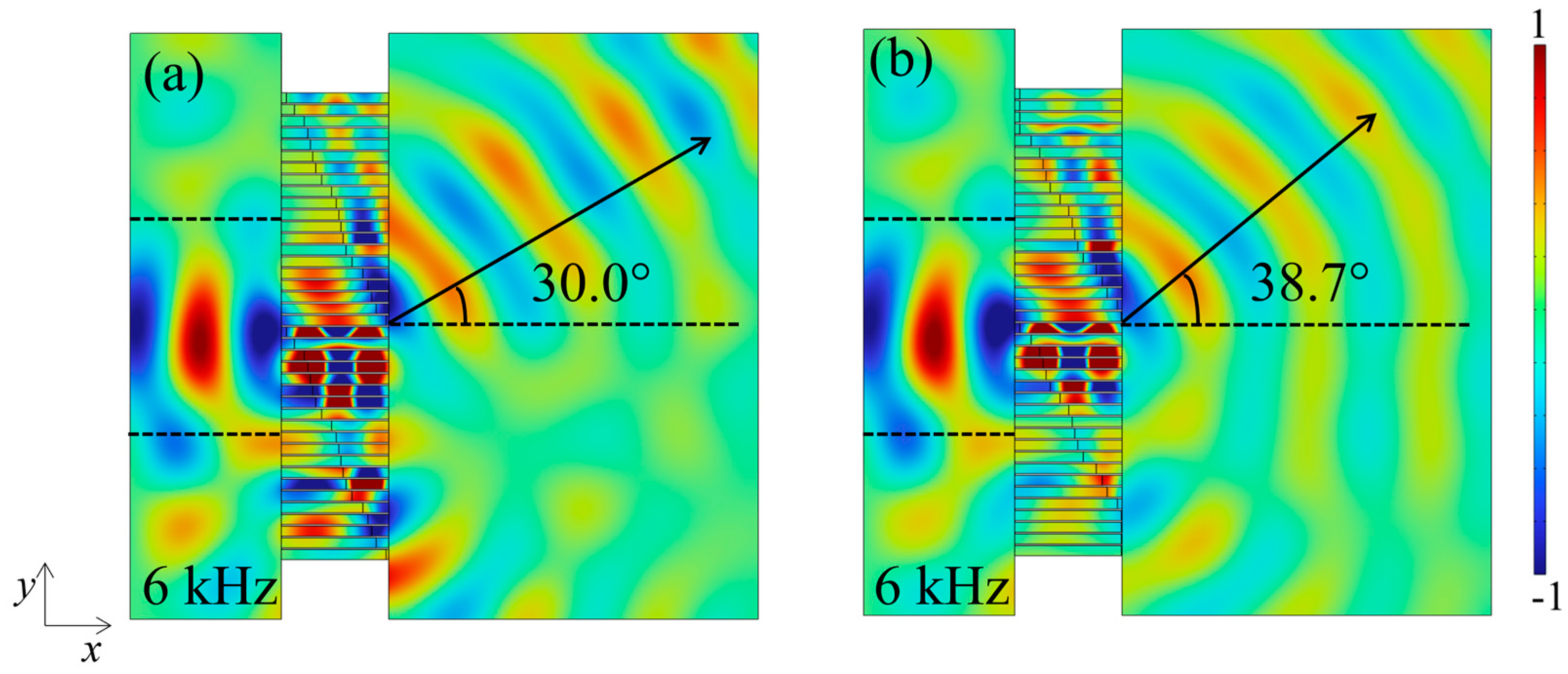
Firstly, the abnormal transmission of passively modulated metasurfaces was realized by changing p. Two different abnormal refraction angles, θt =30° and 38.7°, with operating frequency f = 6 kHz were designed as the targets. The g values for sub-cells 1 and 2 were assumed as 100 and 0, respectively, and the designed values of p were set to match the requirement of phase shift ranging from 0 to 2π. The p-values of the Rith adaptive cell units (Ri = 1 – 40) for different refraction angles in the case of f = 6 kHz are listed in Table A1 (θt = 30°, 38.7°). Full-wave simulations were performed, as shown in Figure 4a,b, from which it can be seen that the vertically incident Gaussian beam can be deflected on demand via the metasurface, realizing the abnormal transmission of the flexural waves. Obviously, the propagation of the transmitted wave matches very well with the theoretical design route.
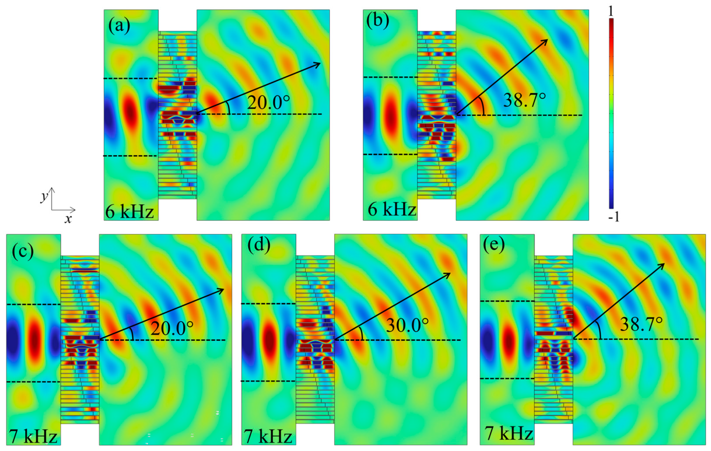
Then, regarding the active modulation of flexural waves, the geometrical parameters of the unit cells were fixed, and abnormal transmission was achieved by varying the g from the negative proportional feedback control strategy applied in the sub-cells. The target angles for transmitted waves are assumed to be 20° and 38.7° when the incident frequency is 6 kHz, and at 7 kHz, these angles are assumed to be 20°, 30°, and 38.7°, respectively. Additionally, the used values of g for the active modulation are provided in Table A2, and the active tunability performance is shown in Figure 5. The simulated angles and target angles basically coincide with each other, which proves the effectiveness and reliability of the active metasurface based on the piezoelectrical effects and negative proportional feedback control technique. Meanwhile, the angles we designed are coincident at different operating frequencies, which suggests the reproducibility of the study. Moreover, it can be observed in Figure 4 and Figure 5 that the main energy of the beam is concentrated in the designed deflection route, but there is still a small amount of energy appearing outside the designed angle, which belongs to the higher-order diffraction [51].
3.3. Realization of Focus Functionality
In this subsection, the focusing functionality of flexural waves via the passively modulated and actively modulated metasurface is detailed separately. For a positively incident flexural wave, the phase distribution along the x-axis is calculated using Equation (17) within different operating frequencies and focusing point locations. The phase distribution is symmetrically distributed about the y-axis, and thus only 20 adaptive unit cells at one side of the y-axis need to be calculated.
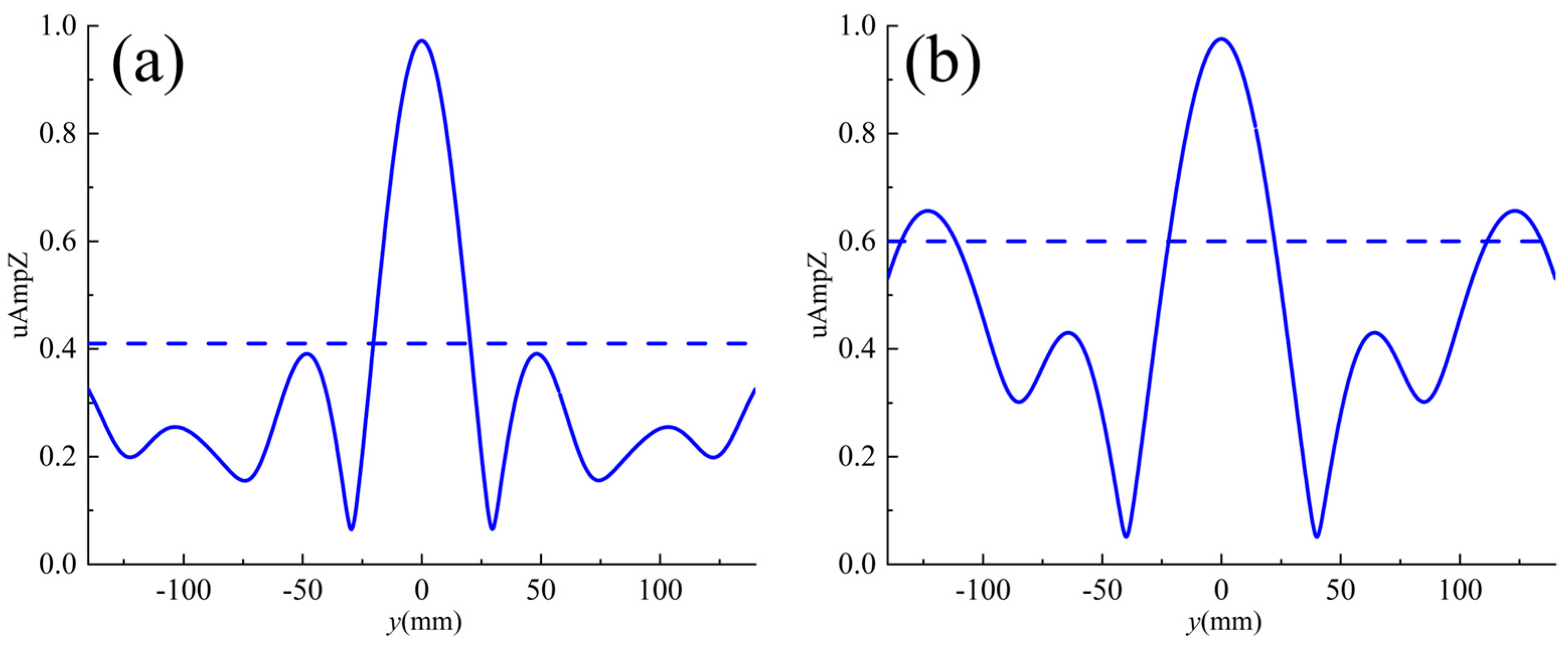
In the FEM simulation, a unit displacement along the -z direction is applied to the left side of the metasurface for the excitation of the flexural wave. We designed passively modulated metasurfaces, which are expected to realize two focal points, (100 mm, 0) and (120 mm, 0), with different focal lengths at a functional frequency of 6 kHz by varying the p and their design values, as shown in Table A1. Figure 6a,b show the numerically calculated out-of-plane displacement plots (z-direction) with the designed focal points (100 mm, 0) and (120 mm, 0) marked with black dashed crosses. It can be clearly seen that the flexural wave is incident vertically on the left side, and the transmitted wave on the right side produces a focusing phenomenon, with a clear focusing phenomenon at the position of the design focal point. To further demonstrate the flexural wave focusing effect obtained with our designed metasurface, the normalized displacement amplitude on the straight line x = x0 where the focal point is located was calculated. Figure 7a,b show the normalized displacement amplitude on the line of x = x0 where the design focus is located, in which the blue solid line is the displacement amplitude at x = x0 and the horizontal blue dashed line denotes the displacement amplitude of the incident wave. From Figure 7, it can be seen that the vibration amplitude at the focal point of the design target is several times larger than the displacement amplitude of the incident wave, and the highest point of the amplitude is at y = 0 mm.
Apart from passive adjustment, an actively metasurface was also designed to achieve the focusing of flexural waves. In this case, different focuses at different operating frequencies were required without changing the geometry of the metasurface. Table A3 presents the design values of g used in the sub-cells for achieving active wave focusing. From Figure 8a,b, it can be seen that the displacements of transmitted wave fields are concentrated in the positions (80 mm, 0) and (120 mm, 0), which is in accordance with the design focal points at 6 kHz. Similarly, at another frequency of 7 kHz, three sets of focal points, (80 mm, 0), (100 mm, 0), and (120 mm, 0), were selected, and the verified performance is shown in Figure 8c–e. Figure 9a–e correspond sequentially to the normalized displacement amplitude on the line x = x0, where the focus is located in Figure 8a–e. As shown in Figure 9, the displacement amplitude at the focusing point far exceeds that of the surrounding region.
3.4. Transforming Guided Wave
In addition to the functions described above, the metasurface can also transform circular waves into plane waves. The transformation of the guided wave was investigated using a focused metasurface model (80 mm, 0) with a displacement in the -z direction applied at coordinates (x,y) = (−80 mm, 0) to excite the circular wave. Figure 10 shows the out-of-plane amplitude plot (z-direction) of a circular wave converted to a plane wave at operating frequencies of (a) f = 6 kHz and (b) 7 kHz. From Figure 10, it can be seen that the circular wave formed by the point source excitation as the incident applied on the left side can be successfully transformed into a plane wave when propagating through the transmitted field, completing the waveform transformation as designed. Numerical simulation results demonstrate that the metasurface not only achieves flexural wave focusing but also transforms circular waves into plane waves.
4. Conclusions
In the present study, a tunable metasurface consisting of adaptive unit cells attached with piezoelectrical actuators and sensors was achieved by applying the negative proportional feedback control strategy. The flexural motion of the metasurface was derived based on the equivalent parameters of the adaptive unit cells. Employing the TMM, the analytical model was established to predict the transmittance and the phase shift of flexural waves propagating through the metasurface, and the validity was verified by comparing the results to those from FEM simulations. Based on the generalized Snell’s law, a metasurface with 40 adaptive unit cells was designed. The passively modulated metasurface was constructed by changing the proportion of the adaptive unit cell occupied by sub-cells, and abnormal modulation flexural waves were achieved at 6 kHz. With the fixed geometrical parameters of the passively modulated metasurface, different phase gradients were generated by adjusting the negative proportional feedback system control gain. Full-wave simulations were performed in finite elements, and the metasurface achieved functions such as the abnormal transmission of multiple angles and the planar lensing of multiple positions at different operating frequencies. A comparison of the theoretical design and finite element simulations shows that this study is reproducible and reliable, which proves the feasibility of the design structure and method. The introduction of a negative proportional positive feedback control strategy provides an active method for adjusting the phase gradient to modulate flexural waves.
Author Contributions
Conceptualization, B.L. and J.L.; methodology, B.L. and J.L.; software, B.L. and J.L.; validation, B.L., J.L. and W.L.; formal analysis, B.L. and J.L.; investigation, J.L., W.L. and Q.M.; resources, B.L. and J.L.; data curation, B.L. and J.L.; writing—original draft preparation, B.L. and J.L.; writing—review and editing, B.L. and J.L.; visualization, B.L., J.L., W.L. and Q.M.; supervision, J.L.; project administration, J.L.; funding acquisition, J.L. All authors have read and agreed to the published version of the manuscript.
Funding
This research was funded by the National Natural Science Foundation of China, grant number 52365009, the Natural Science Foundation of Hainan Province, grant number 122MS004, and the Fundamental Research Funds for the Central Universities, grant number 3072022JC2601.
Institutional Review Board Statement
Not applicable.
Informed Consent Statement
Not applicable.
Data Availability Statement
The data presented in this study are available on request from the corresponding author due to privacy reasons.
Conflicts of Interest
The authors declare no conflicts of interest.
Appendix A
The following three tables show the p and g with values for the adaptive unit cells at different frequencies. Among them, Table A1 reflects the passively modulated metasurfaces to regulate the flexural wave by changing the geometrical structure, and Table A2 and Table A3 reflect the use of control gain to regulate the flexural wave with fixed metasurface geometrical structure.

Table A1.
The p of the Rith adaptive unit cell for abnormal refraction and focusing in passive modulation.
Table A1.
The p of the Rith adaptive unit cell for abnormal refraction and focusing in passive modulation.
| Ri | The p of the Adaptive Unit Cell at 6 kHz | |||||
|---|---|---|---|---|---|---|
| Abnormal Transmittance | Focusing | |||||
| θt = 30° | θt = 38.7° | x0 = 100 mm | x0 = 120 mm | |||
| 1 | 0.047 | 0.047 | 0.047 | 0.047 | ||
| 2 | 0.122 | 0.153 | 0.055 | 0.055 | ||
| 3 | 0.213 | 0.233 | 0.069 | 0.064 | ||
| 4 | 0.247 | 0.265 | 0.102 | 0.091 | ||
| 5 | 0.27 | 0.292 | 0.169 | 0.141 | ||
| 6 | 0.292 | 0.33 | 0.216 | 0.197 | ||
| 7 | 0.32 | 0.423 | 0.242 | 0.234 | ||
| 8 | 0.375 | 0.503 | 0.263 | 0.25 | ||
| 9 | 0.467 | 0.536 | 0.285 | 0.27 | ||
| 10 | 0.511 | 0.559 | 0.313 | 0.291 | ||
| 11 | 0.536 | 0.588 | 0.366 | 0.319 | ||
| 12 | 0.555 | 0.638 | 0.473 | 0.375 | ||
| 13 | 0.575 | 0.759 | 0.522 | 0.477 | ||
| 14 | 0.602 | 0.816 | 0.55 | 0.52 | ||
| 15 | 0.658 | 0.861 | 0.578 | 0.548 | ||
| 16 | 0.759 | 0.956 | 0.627 | 0.573 | ||
| 17 | 0.806 | 0.994 | 0.764 | 0.613 | ||
| 18 | 0.841 | 0.994 | 0.828 | 0.736 | ||
| 19 | 0.883 | 0.994 | 0.895 | 0.813 | ||
| 20 | 0.975 | 0.994 | 0.992 | 0.866 | ||
| 21 | 0.047 | 0.047 | ||||
| 22 | 0.122 | 0.047 | ||||
| 23 | 0.213 | 0.047 | ||||
| 24 | 0.247 | 0.047 | ||||
| 25 | 0.27 | 0.153 | ||||
| 26 | 0.292 | 0.233 | ||||
| 27 | 0.32 | 0.265 | ||||
| 28 | 0.375 | 0.292 | ||||
| 29 | 0.467 | 0.33 | ||||
| 30 | 0.511 | 0.423 | ||||
| 31 | 0.536 | 0.503 | ||||
| 32 | 0.555 | 0.536 | ||||
| 33 | 0.575 | 0.559 | ||||
| 34 | 0.602 | 0.588 | ||||
| 35 | 0.658 | 0.638 | ||||
| 36 | 0.759 | 0.759 | ||||
| 37 | 0.806 | 0.816 | ||||
| 38 | 0.841 | 0.861 | ||||
| 39 | 0.883 | 0.956 | ||||
| 40 | 0.975 | 0.994 | ||||
Table A2.
The g of the Rith adaptive unit cell with abnormal refraction during active modulation.
| Ri | The g of the Adaptive Unit Cell | |||||||||
|---|---|---|---|---|---|---|---|---|---|---|
| 6 kHz | 7 kHz | |||||||||
| θt = 20° | θt = 38.7° | θt = 20° | θt = 30° | θt = 38.7° | ||||||
| Sub-Cell1 | Sub-Cell2 | Sub-Cell1 | Sub-Cell2 | Sub-Cell1 | Sub-Cell2 | Sub-Cell1 | Sub-Cell2 | Sub-Cell1 | Sub-Cell2 | |
| 1 | 100 | 16.805 | 0 | 2.999 | 100 | 7.749 | 100 | 8.731 | 100 | 9.572 |
| 2 | 100 | 14.507 | 0 | 5.8 | 100 | 5.342 | 100 | 3.81 | 100 | 8.58 |
| 3 | 100 | 10.645 | 0 | 2.069 | 100 | 1.786 | 100 | 13.6 | 100 | 6.251 |
| 4 | 100 | 11.585 | 0 | 0.705 | 100 | 1.867 | 100 | 4.515 | 100 | 8.263 |
| 5 | 100 | 13.758 | 0 | 2.363 | 100 | 2.75 | 100 | 6.301 | 0.6 | 0 |
| 6 | 100 | 16.46 | 0 | 4.478 | 100 | 3.865 | 100 | 8.533 | 16.84 | 0 |
| 7 | 100 | 18.877 | 0 | 6.772 | 100 | 4.602 | 100 | 10.546 | 53.001 | 0 |
| 8 | 100 | 18.225 | 0 | 7.986 | 100 | 3.091 | 100 | 10.038 | 54.47 | 0 |
| 9 | 100 | 12.318 | 0 | 6.826 | 0 | 9.636 | 100 | 5.223 | 22.518 | 0 |
| 10 | 100 | 12.594 | 0 | 9.37 | 0 | 10.811 | 100 | 5.484 | 32.928 | 0 |
| 11 | 100 | 16.023 | 0 | 14.891 | 0 | 14.472 | 100 | 8.344 | 60.358 | 0 |
| 12 | 100 | 21.612 | 0 | 23.931 | 0 | 20.047 | 100 | 13.037 | 100 | 0.456 |
| 13 | 100 | 28.629 | 100 | 8.643 | 0 | 27.227 | 100 | 19.006 | 100 | 4.62 |
| 14 | 100 | 36.432 | 100 | 13.586 | 0 | 36.009 | 100 | 25.756 | 100 | 1.162 |
| 15 | 100 | 37.548 | 100 | 15.148 | 0 | 42.483 | 100 | 26.901 | 100 | 10.512 |
| 16 | 100 | 21.838 | 9.43 | 100 | 0 | 40.168 | 100 | 13.775 | 100 | 1.579 |
| 17 | 100 | 23.974 | 27.056 | 100 | 0 | 59.865 | 100 | 15.926 | 100 | 3.479 |
| 18 | 100 | 36.205 | 51.797 | 100 | 1.533 | 100 | 100 | 27.188 | 100 | 12.509 |
| 19 | 100 | 55.872 | 82.227 | 100 | 8.473 | 100 | 100 | 46.716 | 100 | 30.409 |
| 20 | 100 | 0 | 0 | 0 | 12.369 | 100 | 100 | 0 | 100 | 0 |
| 21 | 100 | 16.805 | 0 | 0 | 100 | 7.749 | 100 | 8.731 | 100 | 4.123 |
| 22 | 100 | 14.507 | 0 | 0.884 | 100 | 5.342 | 100 | 3.81 | 100 | 2.966 |
| 23 | 100 | 10.645 | 0 | 0.035 | 100 | 1.786 | 100 | 13.6 | 100 | 0.695 |
| 24 | 100 | 11.585 | 0 | 1.857 | 100 | 1.867 | 100 | 4.515 | 100 | 1.945 |
| 25 | 100 | 13.758 | 0 | 4.743 | 100 | 2.75 | 100 | 6.301 | 100 | 4.264 |
| 26 | 100 | 16.46 | 0 | 8.502 | 100 | 3.865 | 100 | 8.533 | 100 | 7.227 |
| 27 | 100 | 18.877 | 0 | 12.894 | 100 | 4.602 | 100 | 10.546 | 100 | 10.274 |
| 28 | 100 | 18.225 | 0 | 16.395 | 100 | 3.091 | 100 | 10.038 | 100 | 11.102 |
| 29 | 100 | 12.318 | 0 | 17.327 | 0 | 9.636 | 100 | 5.223 | 100 | 7.587 |
| 30 | 100 | 12.594 | 0 | 24.902 | 0 | 10.811 | 100 | 5.484 | 100 | 9.73 |
| 31 | 100 | 16.023 | 0 | 39.7 | 0 | 14.472 | 100 | 8.344 | 100 | 15.647 |
| 32 | 100 | 21.612 | 0 | 65.535 | 0 | 20.047 | 100 | 13.037 | 100 | 25.399 |
| 33 | 100 | 28.629 | 100 | 27.918 | 0 | 27.227 | 100 | 19.006 | 100 | 39.729 |
| 34 | 100 | 36.432 | 100 | 44.143 | 0 | 36.009 | 100 | 25.756 | 100 | 60.514 |
| 35 | 100 | 37.548 | 100 | 60.131 | 0 | 42.483 | 100 | 26.901 | 100 | 82.342 |
| 36 | 100 | 21.838 | 100 | 64.353 | 0 | 40.168 | 100 | 13.775 | 21.271 | 100 |
| 37 | 100 | 23.974 | 63.58 | 0 | 0 | 59.865 | 100 | 15.926 | 100 | 59.331 |
| 38 | 100 | 36.205 | 4.688 | 0 | 1.533 | 100 | 100 | 27.188 | 100 | 35.139 |
| 39 | 100 | 55.872 | 24.714 | 0 | 8.473 | 100 | 100 | 46.716 | 100 | 8.848 |
| 40 | 100 | 0 | 1.95 | 0 | 12.369 | 100 | 100 | 0 | 80.731 | 0 |
Table A3.
The g of the Rith adaptive unit cell with focusing during active modulation.
| Ri | The g of the Rith Adaptive Unit Cell | |||||||||
|---|---|---|---|---|---|---|---|---|---|---|
| 6 kHz | 7 kHz | |||||||||
| x0 = 80 mm | x0 = 120 mm | x0 = 80 mm | x0 = 100 mm | x0 = 120 mm | ||||||
| Sub-Cell1 | Sub-Cell2 | Sub-Cell1 | Sub-Cell2 | Sub-Cell1 | Sub-Cell2 | Sub-Cell1 | Sub-Cell2 | Sub-Cell1 | Sub-Cell1 | |
| 1 | 0 | 1.435 | 0 | 3.533 | 0 | 1.73 | 0 | 1.93 | 0 | 3.534 |
| 2 | 0 | 1.497 | 0 | 3.527 | 0 | 1.816 | 0 | 1.958 | 0 | 3.529 |
| 3 | 0 | 1.674 | 0 | 3.508 | 0 | 1.962 | 0 | 2.077 | 0 | 3.509 |
| 4 | 0 | 1.485 | 0 | 2.984 | 0 | 1.746 | 0 | 1.736 | 0 | 2.985 |
| 5 | 0 | 0.192 | 0 | 1.254 | 0 | 0.525 | 0 | 0.167 | 0 | 1.25 |
| 6 | 0 | 0.06 | 0 | 0.559 | 0 | 0.311 | 0 | 0.065 | 0 | 0.56 |
| 7 | 0 | 1.038 | 0 | 0.97 | 0 | 1.127 | 0 | 0.662 | 0 | 0.971 |
| 8 | 0 | 2.752 | 0 | 3.002 | 0 | 5.623 | 0 | 2.328 | 0 | 1.946 |
| 9 | 0 | 1.599 | 0 | 3.283 | 0 | 4.663 | 0 | 4.612 | 0 | 3.285 |
| 10 | 0 | 4.53 | 0 | 4.819 | 0 | 3.176 | 0 | 7.419 | 0 | 4.82 |
| 11 | 0 | 6.835 | 0 | 5.322 | 0 | 4.997 | 0 | 9.412 | 0 | 5.324 |
| 12 | 0 | 5.714 | 0 | 3.5 | 0 | 3.515 | 0 | 7.637 | 0 | 2.414 |
| 13 | 0 | 10.698 | 2.94 | 0 | 0 | 7.347 | 0 | 12.01 | 2.947 | 0 |
| 14 | 0 | 21.957 | 18.275 | 0 | 0 | 16.2 | 0 | 22.068 | 18.285 | 0 |
| 15 | 0 | 42.822 | 39.794 | 0 | 0 | 32.079 | 0 | 39.881 | 39.808 | 0 |
| 16 | 0 | 83.017 | 51.791 | 0 | 0 | 60.175 | 0 | 71.127 | 51.808 | 0 |
| 17 | 10.033 | 100 | 16.464 | 0 | 1.457 | 100 | 83.942 | 0 | 16.474 | 0 |
| 18 | 34.214 | 100 | 19.949 | 0 | 21.692 | 100 | 89.628 | 0 | 19.959 | 0 |
| 19 | 66.646 | 100 | 22.789 | 0 | 48.817 | 100 | 93.326 | 0 | 22.8 | 0 |
| 20 | 98.763 | 100 | 17.278 | 0 | 76.565 | 100 | 74.579 | 0 | 17.288 | 0 |
References
- Yi, K.; Collet, M.; Ichchou, M.; Li, L. Flexural waves focusing through shunted piezoelectric patches. Smart Mater. Struct. 2016, 25, 075007. [Google Scholar] [CrossRef]
- Cao, L.; Yang, Z.; Xu, Y.; Fan, S.-W.; Zhu, Y.; Chen, Z.; Li, Y.; Assouar, B. Flexural wave absorption by lossy gradient elastic metasurface. J. Mech. Phys. Solids 2020, 143, 104052. [Google Scholar] [CrossRef]
- Shen, Y.; Xu, Y.; Liu, F.; Yang, Z. Metasurface-guided flexural waves and their manipulations. Int. J. Mech. Sci. 2023, 257, 108538. [Google Scholar] [CrossRef]
- Chen, A.-L.; Wang, Y.-S.; Wang, Y.-F.; Zhou, H.-T.; Yuan, S.-M. Design of Acoustic/Elastic Phase Gradient Metasurfaces: Principles, Functional Elements, Tunability, and Coding. Appl. Mech. Rev. 2022, 74, 020801. [Google Scholar] [CrossRef]
- Wang, W.; Iglesias, J.; Jin, Y.; Djafari-Rouhani, B.; Khelif, A. Experimental realization of a pillared metasurface for flexural wave focusing. APL Mater. 2021, 9, 051125. [Google Scholar] [CrossRef]
- Feng, L.; Liu, X.-P.; Lu, M.-H.; Chen, Y.-B.; Chen, Y.-F.; Mao, Y.-W.; Zi, J.; Zhu, Y.-Y.; Zhu, S.-N.; Ming, N.-B. Acoustic Backward-Wave Negative Refractions in the Second Band of a Sonic Crystal. Phys. Rev. Lett. 2006, 96, 014301. [Google Scholar] [CrossRef]
- Lu, Y.; Srivastava, A. Level Repulsion and Band Sorting in Phononic Crystals. J. Mech. Phys. Solids 2017, 111, 100–112. [Google Scholar] [CrossRef]
- Liu, Z.; Zhang, X.; Mao, Y.; Zhu, Y.Y.; Yang, Z.; Chan, C.T.; Sheng, P. Locally Resonant Sonic Materials. Science 2000, 289, 1734–1736. [Google Scholar] [CrossRef] [PubMed]
- Oh, J.H.; Kwon, Y.E.; Lee, H.J.; Kim, Y.Y. Elastic metamaterials for independent realization of negativity in density and stiffness. Sci. Rep. 2016, 6, 23630. [Google Scholar] [CrossRef] [PubMed]
- Reynolds, M.; Daley, S. An active viscoelastic metamaterial for isolation applications. Smart Mater. Struct. 2014, 23, 045030. [Google Scholar] [CrossRef]
- Sun, S.; He, Q.; Xiao, S.; Xu, Q.; Li, X.; Zhou, L. Gradient-index meta-surfaces as a bridge linking propagating waves and surface waves. Nat. Mater. 2012, 11, 426–431. [Google Scholar] [CrossRef]
- Yu, N.; Capasso, F. Flat optics with designer metasurfaces. Nat. Mater. 2014, 13, 139–150. [Google Scholar] [CrossRef]
- Zhang, J.; Kosugi, Y.; Otomo, A.; Nakano, Y.; Tanemura, T. Active metasurface modulator with electro-optic polymer using bimodal plasmonic resonance. Opt. Express 2017, 25, 30304–30311. [Google Scholar] [CrossRef]
- Qi, S.; Li, Y.; Assouar, B. Acoustic Focusing and Energy Confinement Based on Multilateral Metasurfaces. Phys. Rev. Appl. 2017, 7, 054006. [Google Scholar] [CrossRef]
- Xie, B.; Tang, K.; Cheng, H.; Liu, Z.; Chen, S.; Tian, J. Coding Acoustic Metasurfaces. Adv. Mater. 2017, 29, 1603507. [Google Scholar] [CrossRef] [PubMed]
- Liang, Z.; Li, J. Extreme Acoustic Metamaterial by Coiling Up Space. Phys. Rev. Lett. 2012, 108, 114301. [Google Scholar] [CrossRef] [PubMed]
- Fan, S.-W.; Zhao, S.-D.; Cao, L.; Zhu, Y.; Chen, A.-L.; Wang, Y.-F.; Donda, K.; Wang, Y.-S.; Assouar, B. Reconfigurable curved metasurface for acoustic cloaking and illusion. Phys. Rev. B 2020, 101, 024104. [Google Scholar] [CrossRef]
- Li, Y.; Liang, B.; Gu, Z.-M.; Zou, X.-Y.; Cheng, J.-C. Reflected wavefront manipulation based on ultrathin planar acoustic metasurfaces. Sci. Rep. 2013, 3, 2546. [Google Scholar] [CrossRef] [PubMed]
- Schwan, L.; Umnova, O.; Boutin, C. Sound absorption and reflection from a resonant metasurface: Homogenisation model with experimental validation. Wave Motion 2017, 72, 154–172. [Google Scholar] [CrossRef]
- Shen, Y.; Xu, Y.; Liu, F.; Wang, F.; Yang, Z. 3D-printed meta-slab for focusing flexural waves in broadband. Extrem. Mech. Lett. 2021, 48, 101410. [Google Scholar] [CrossRef]
- Zhu, H.; Semperlotti, F. Anomalous Refraction of Acoustic Guided Waves in Solids with Geometrically Tapered Metasurfaces. Phys. Rev. Lett. 2016, 117, 034302. [Google Scholar] [CrossRef]
- Zeng, L.; Zhang, J.; Liu, Y.; Zhao, Y.; Hu, N. Asymmetric transmission of elastic shear vertical waves in solids. Ultrasonics 2019, 96, 34–39. [Google Scholar] [CrossRef] [PubMed]
- Hu, Y.; Li, M.; Liu, H.; Li, B. Broadband manipulation of flexural waves based on phase-modulated elastic metasurfaces. Eng. Struct. 2023, 275, 115209. [Google Scholar] [CrossRef]
- Kim, M.S.; Lee, W.R.; Kim, Y.Y.; Oh, J.H. Transmodal elastic metasurface for broad angle total mode conversion. Appl. Phys. Lett. 2018, 112, 241905. [Google Scholar] [CrossRef]
- Tian, Z.; Yu, L. Elastic Phased Diffraction Gratings for Manipulation of Ultrasonic Guided Waves in Solids. Phys. Rev. Appl. 2019, 11, 024052. [Google Scholar] [CrossRef]
- Lee, H.; Lee, J.K.; Seung, H.M.; Kim, Y.Y. Mass-stiffness substructuring of an elastic metasurface for full transmission beam steering. J. Mech. Phys. Solids 2018, 112, 577–593. [Google Scholar] [CrossRef]
- Xu, Y.; Zhou, X.; Wang, W.; Wang, L.; Peng, F.; Li, B. On natural frequencies of non-uniform beams modulated by finite periodic cells. Phys. Lett. A 2016, 380, 3278–3283. [Google Scholar] [CrossRef]
- Cao, L.; Yang, Z.; Xu, Y. Steering elastic SH waves in an anomalous way by metasurface. J. Sound Vib. 2018, 418, 1–14. [Google Scholar] [CrossRef]
- Xu, Y.; Cao, L.; Peng, P.; Zhou, X.; Assouar, B.; Yang, Z. Beam splitting of flexural waves with a coding meta-slab. Appl. Phys. Express 2019, 12, 097002. [Google Scholar] [CrossRef]
- Zhu, H.; Walsh, T.F.; Semperlotti, F. Total-internal-reflection elastic metasurfaces: Design and application to structural vibration isolation. Appl. Phys. Lett. 2018, 113, 221903. [Google Scholar] [CrossRef]
- Liu, Y.; Liang, Z.; Liu, F.; Diba, O.; Lamb, A.; Li, J. Source Illusion Devices for Flexural Lamb Waves Using Elastic Metasurfaces. Phys. Rev. Lett. 2017, 119, 034301. [Google Scholar] [CrossRef]
- Cao, L.; Yang, Z.; Xu, Y.; Fan, S.-W.; Zhu, Y.; Chen, Z.; Vincent, B.; Assouar, B. Disordered Elastic Metasurfaces. Phys. Rev. Appl. 2020, 13, 014054. [Google Scholar] [CrossRef]
- Su, X.; Lu, Z.; Norris, A.N. Elastic metasurfaces for splitting SV- and P-waves in elastic solids. J. Appl. Phys. 2018, 123, 091701. [Google Scholar] [CrossRef]
- Lin, Z.; Xu, W.; Xuan, C.; Qi, W.; Wang, W. Modular elastic metasurfaces with mass oscillators for transmitted flexural wave manipulation. J. Phys. D Appl. Phys. 2021, 54, 255303. [Google Scholar] [CrossRef]
- Xu, W.; Zhang, M.; Lin, Z.; Liu, C.; Qi, W.; Wang, W. Anomalous refraction manipulation of Lamb waves using single-groove metasurfaces. Phys. Scr. 2019, 94, 105807. [Google Scholar] [CrossRef]
- Zhou, W.; Wang, S.; Wu, Q.; Xu, X.; Huang, X.; Huang, G.; Liu, Y.; Fan, Z. An inverse design paradigm of multi-functional elastic metasurface via data-driven machine learning. Mater. Des. 2023, 226, 111560. [Google Scholar] [CrossRef]
- Yuan, S.-M.; Chen, A.-L.; Du, X.-Y.; Zhang, H.-W.; Assouar, B.; Wang, Y.-S. Reconfigurable flexural waves manipulation by broadband elastic metasurface. Mech. Syst. Signal Process. 2022, 179, 109371. [Google Scholar] [CrossRef]
- Li, S.; Xu, J.; Tang, J. Tunable modulation of refracted lamb wave front facilitated by adaptive elastic metasurfaces. Appl. Phys. Lett. 2018, 112, 021903. [Google Scholar] [CrossRef]
- Shao, S.; Xia, R.; Li, Z. Tunable piezoelectric metasurface for manipulating multi-mode guided waves in plate. Eng. Struct. 2022, 270, 114917. [Google Scholar] [CrossRef]
- Ren, T.; Liu, C.; Li, F.; Zhang, C. Active tuning of the vibration band gap characteristics of periodic laminated composite metamaterial beams. J. Intell. Mater. Syst. Struct. 2020, 31, 843–859. [Google Scholar] [CrossRef]
- Liu, F.; Shi, P.; Chen, Z.; Shen, Y.; Xu, Y.; Yang, Z. Tunable reflection and broadband absorption of flexural waves by adaptive elastic metasurface with piezoelectric shunting circuits. Smart Mater. Struct. 2023, 32, 055018. [Google Scholar] [CrossRef]
- Yaw, Z.; Zhou, W.; Chen, Z.; Lim, C. Stiffness tuning of a functional-switchable active coding elastic metasurface. Int. J. Mech. Sci. 2021, 207, 106654. [Google Scholar] [CrossRef]
- Li, B.; Hu, Y.; Chen, J.; Su, G.; Liu, Y.; Zhao, M.; Li, Z. Efficient Asymmetric Transmission of Elastic Waves in Thin Plates with Lossless Metasurfaces. Phys. Rev. Appl. 2020, 14, 054029. [Google Scholar] [CrossRef]
- Xu, Y.; Cao, L.; Yang, Z. Deflecting incident flexural waves by nonresonant single-phase meta-slab with subunits of graded thicknesses. J. Sound Vib. 2019, 454, 51–62. [Google Scholar] [CrossRef]
- Qiu, H.; Chen, M.; Huan, Q.; Li, F. Steering and focusing of fundamental shear horizontal guided waves in plates by using multiple-strip metasurfaces. Europhys. Lett. 2019, 127, 46004. [Google Scholar] [CrossRef]
- Lin, Z.; Tol, S. Electroelastic metasurface with resonant piezoelectric shunts for tunable wavefront control. J. Phys. D Appl. Phys. 2023, 56, 164001. [Google Scholar] [CrossRef]
- Chen, Y.; Li, X.; Nassar, H.; Hu, G.-K.; Huang, G. A programmable metasurface for real time control of broadband elastic rays. Smart Mater. Struct. 2018, 27, 115011. [Google Scholar] [CrossRef]
- Wang, G.; Chen, S.; Wen, J. Low-frequency locally resonant band gaps induced by arrays of resonant shunts with Antoniou’s circuit: Experimental investigation on beams. Smart Mater. Struct. 2010, 20, 015026. [Google Scholar] [CrossRef]
- Zhang, H.; Wen, J.-H.; Chen, S.-B.; Wang, G.; Wen, X.-S. Flexural wave band-gaps in phononic metamaterial beam with hybrid shunting circuits. Chin. Phys. B 2015, 24, 036201. [Google Scholar] [CrossRef]
- Li, F.; Zhang, C.; Liu, C. Active tuning of vibration and wave propagation in elastic beams with periodically placed piezoelectric actuator/sensor pairs. J. Sound Vib. 2017, 393, 14–29. [Google Scholar] [CrossRef]
- Xu, Y.; Yang, Z.; Cao, L. Deflecting Rayleigh surface acoustic waves by a meta-ridge with a gradient phase shift. J. Phys. D Appl. Phys. 2018, 51, 175106. [Google Scholar] [CrossRef]
Figure 1.
(a) A 3D model of the adaptive unit cell with a negative proportional feedback control strategy. (b) A 2D model of the 3D adaptive unit cell in (a).
Figure 1.
(a) A 3D model of the adaptive unit cell with a negative proportional feedback control strategy. (b) A 2D model of the 3D adaptive unit cell in (a).
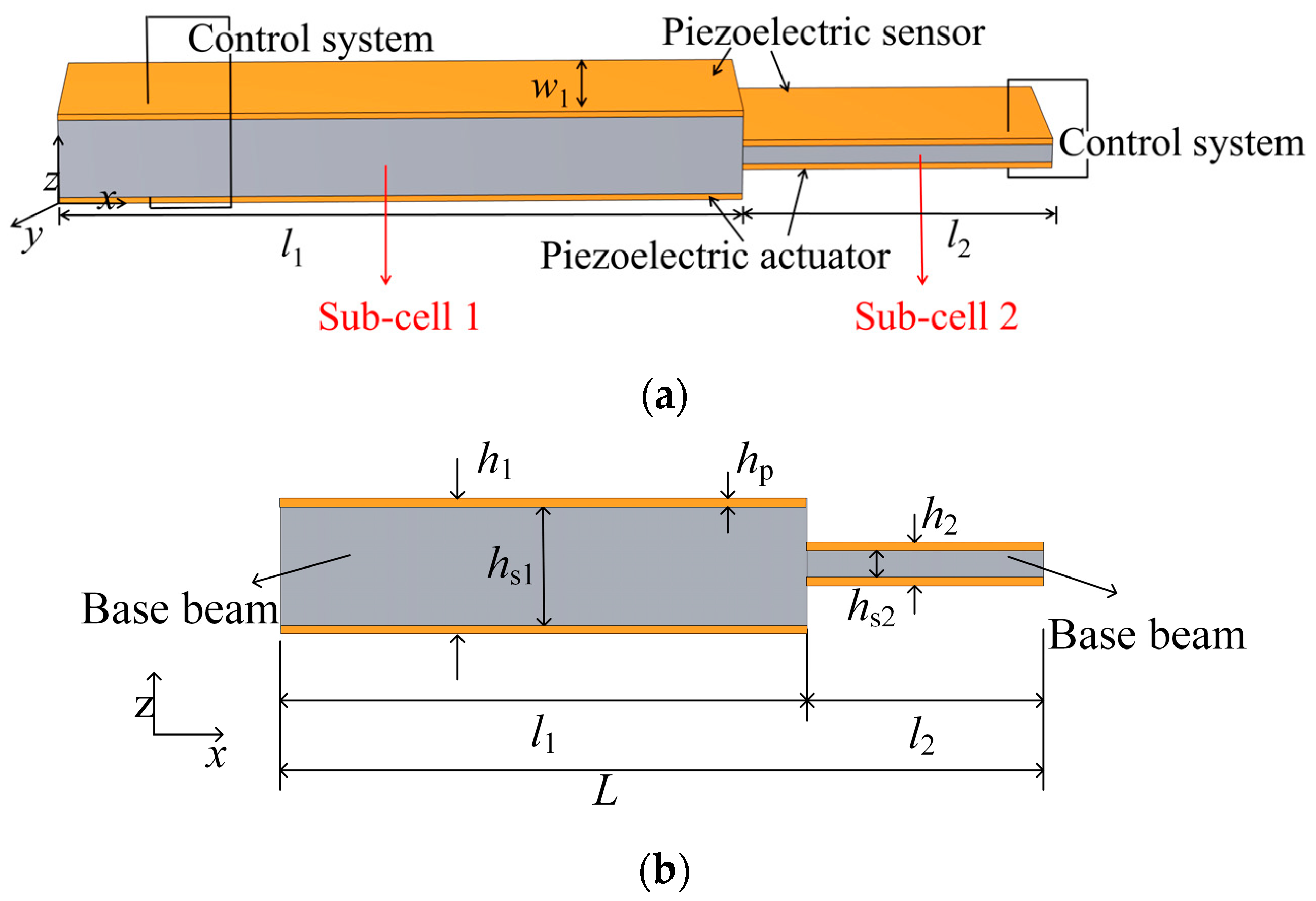
Figure 2.
The basic unit for deriving the transmission coefficient and the phase shift.
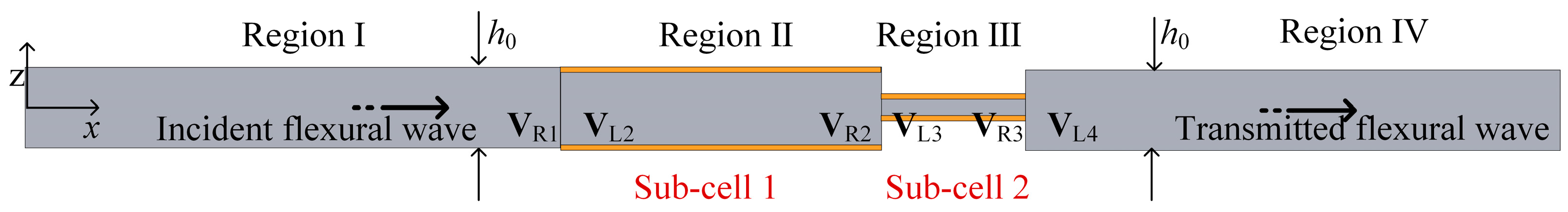
Figure 3.
(a) The phase velocity curve varying with g for f = 6 kHz. (b) The transmission coefficient and phase shift as g increases while p = 0.5. (c) The transmission coefficient and phase shift with respect to varying p at 6 kHz when g is 100 in sub-cell 1 and 0 in sub-cell 2.
Figure 3.
(a) The phase velocity curve varying with g for f = 6 kHz. (b) The transmission coefficient and phase shift as g increases while p = 0.5. (c) The transmission coefficient and phase shift with respect to varying p at 6 kHz when g is 100 in sub-cell 1 and 0 in sub-cell 2.
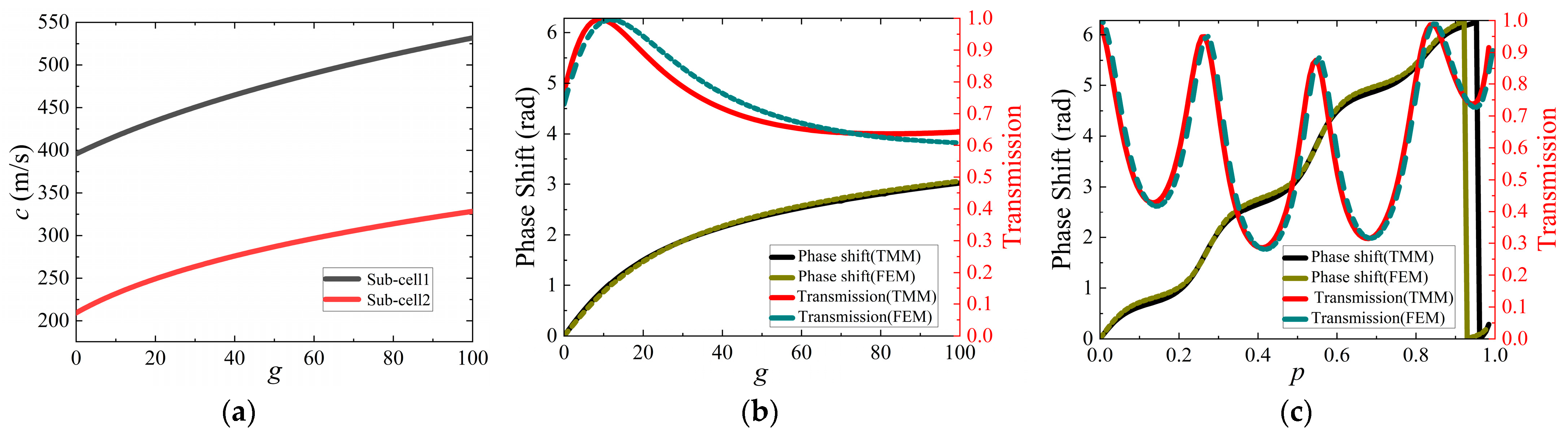
Figure 4.
The out-of-plane displacement diagrams (z-direction) for flexural wave propagation with passive modulation by changing p at f = 6 kHz: the design refraction angles are (a) 30° and (b) 38.7°.
Figure 4.
The out-of-plane displacement diagrams (z-direction) for flexural wave propagation with passive modulation by changing p at f = 6 kHz: the design refraction angles are (a) 30° and (b) 38.7°.

Figure 5.
The out-of-plane displacement diagrams (z-direction) for flexural wave propagation with active modulation by changing g at f = 6 and 7 kHz: the design refractive angles are (a) 20°, (b) 38.7°, (c) 20°, (d) 30°, and (e) 38.7°, respectively.
Figure 5.
The out-of-plane displacement diagrams (z-direction) for flexural wave propagation with active modulation by changing g at f = 6 and 7 kHz: the design refractive angles are (a) 20°, (b) 38.7°, (c) 20°, (d) 30°, and (e) 38.7°, respectively.

Figure 6.
The out-of-plane displacement diagrams (z-direction) for flexural wave propagation with passive modulation by changing p at f = 6 kHz. The design focal positions were (a) (100 mm, 0) and (b) (120 mm, 0).
Figure 6.
The out-of-plane displacement diagrams (z-direction) for flexural wave propagation with passive modulation by changing p at f = 6 kHz. The design focal positions were (a) (100 mm, 0) and (b) (120 mm, 0).
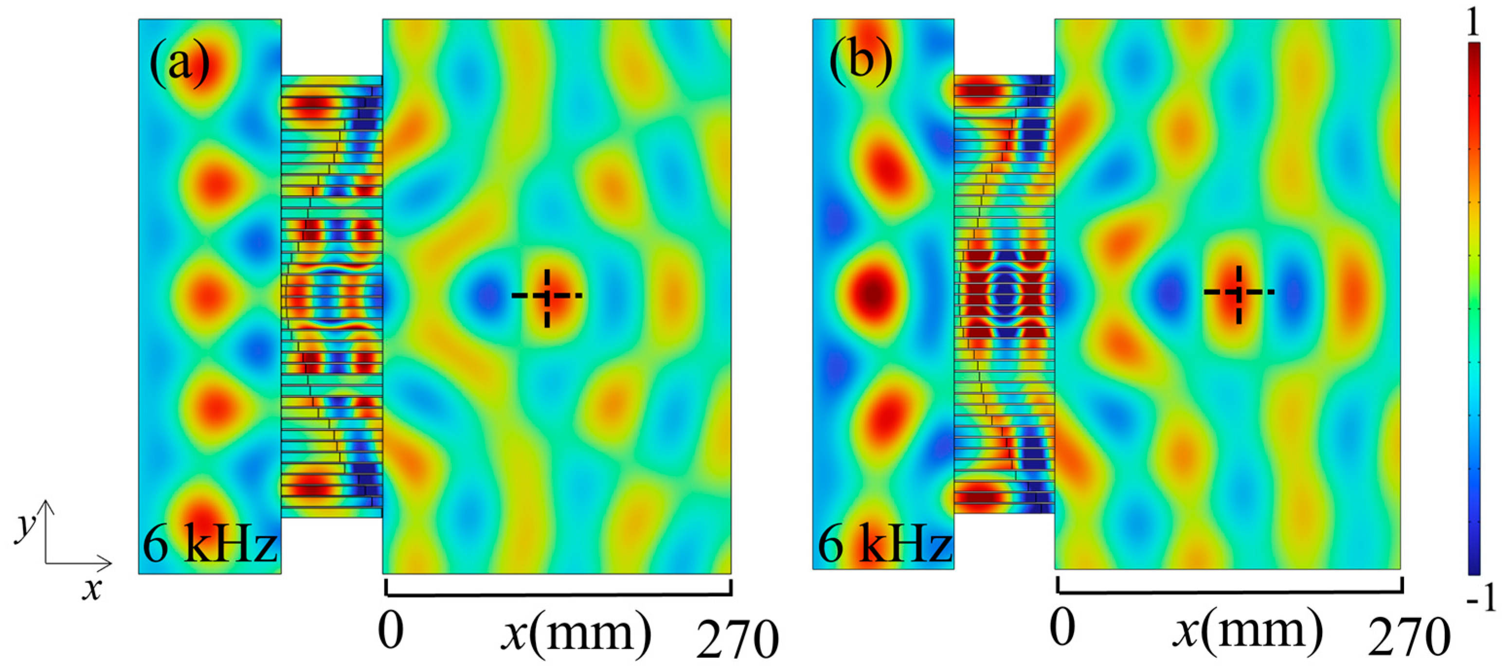
Figure 7.
The normalized amplitude (z-component) of the displacement field along the straight line (a) x0 = 100 mm and (b) x0 = 120 mm when performing focusing (the vertical coordinate is the displacement amplitude).
Figure 7.
The normalized amplitude (z-component) of the displacement field along the straight line (a) x0 = 100 mm and (b) x0 = 120 mm when performing focusing (the vertical coordinate is the displacement amplitude).

Figure 8.
The out-of-plane displacement diagrams (z-direction) for flexural wave propagation with active modulation by changing g at f = 6 and 7 kHz. The design focal positions were (a) (80 mm, 0), (b) (120 mm, 0) (c) (80 mm, 0), (d) (100 mm, 0), and (e) (100 mm, 0).
Figure 8.
The out-of-plane displacement diagrams (z-direction) for flexural wave propagation with active modulation by changing g at f = 6 and 7 kHz. The design focal positions were (a) (80 mm, 0), (b) (120 mm, 0) (c) (80 mm, 0), (d) (100 mm, 0), and (e) (100 mm, 0).
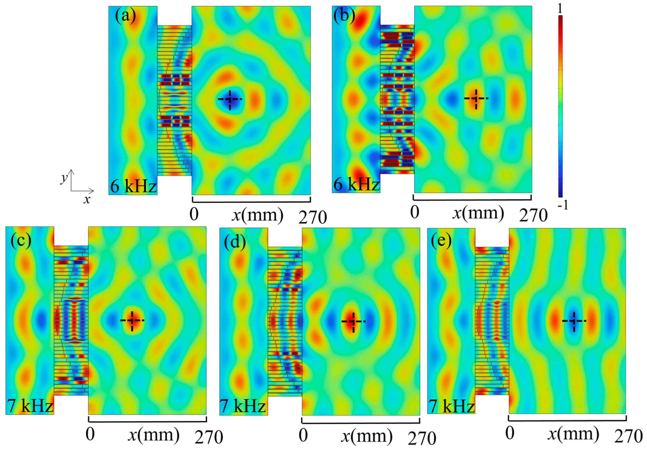
Figure 9.
The normalized amplitude (z-component) for Figure 8. Values along the straight line are (a) x0 = 100 mm, (b) x0 = 120 mm, (c) x0 = 80 mm, (d) x0 = 100 mm, and (e) x0 = 120 mm.
Figure 9.
The normalized amplitude (z-component) for Figure 8. Values along the straight line are (a) x0 = 100 mm, (b) x0 = 120 mm, (c) x0 = 80 mm, (d) x0 = 100 mm, and (e) x0 = 120 mm.
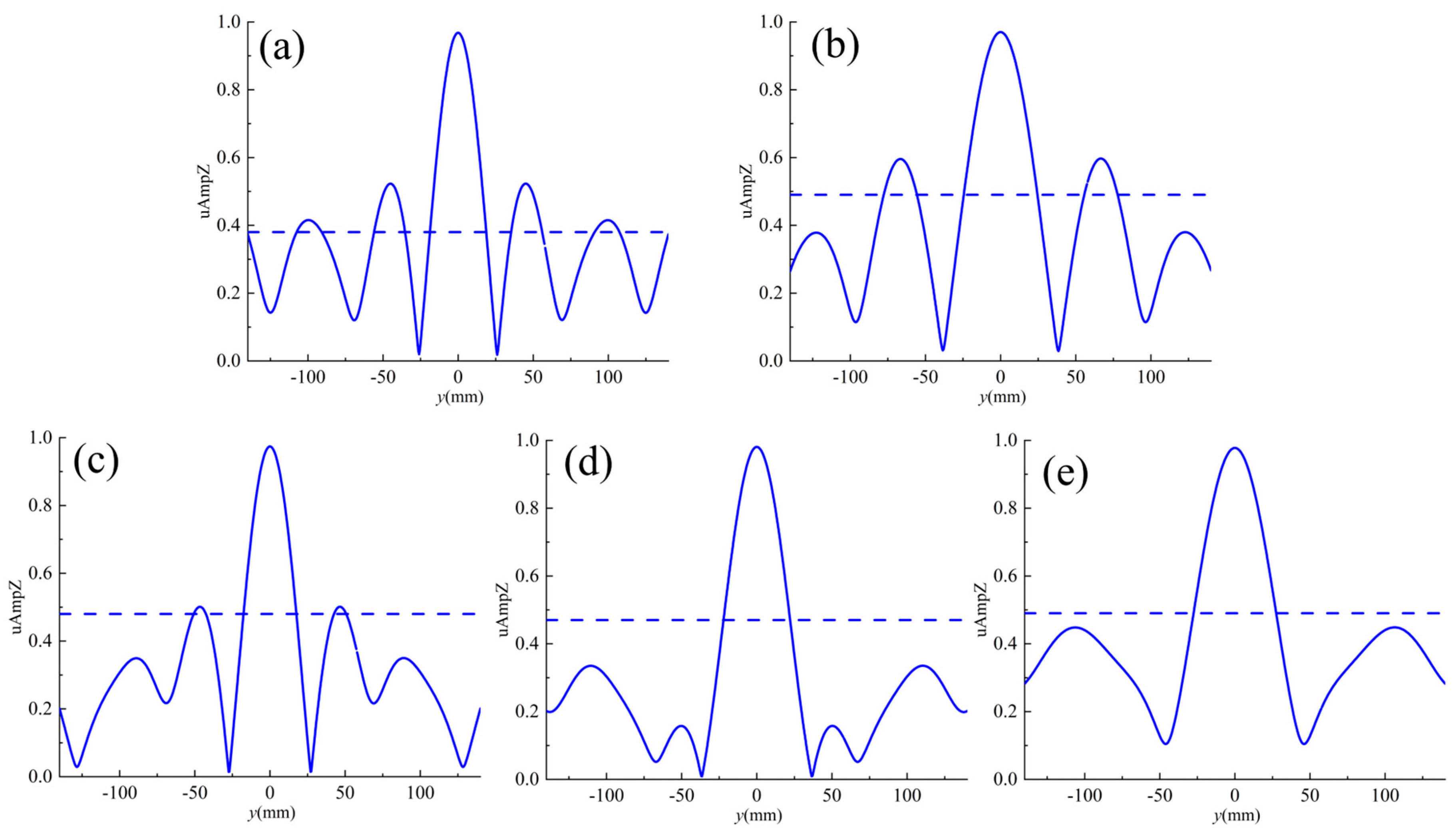
Figure 10.
The out-of-plane displacement diagrams of the transforming guided wave at (a) f = 6 kHz and (b) 7 kHz.
Figure 10.
The out-of-plane displacement diagrams of the transforming guided wave at (a) f = 6 kHz and (b) 7 kHz.
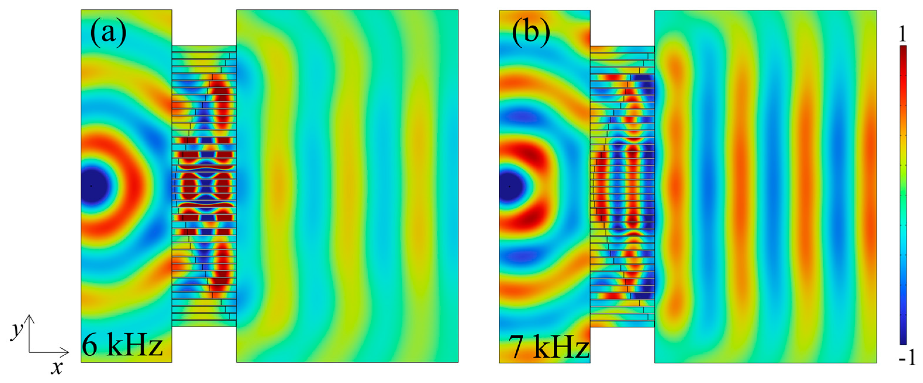
Table 1.
Geometry of the adaptive unit cell.
| h0 | h1 | h2 | hs1 | hs2 | hp | L | w1 |
|---|---|---|---|---|---|---|---|
| 3 mm | 3 mm | 1 mm | 2.6 mm | 0.6 mm | 0.2 mm | 64 mm | 5 mm |
Disclaimer/Publisher’s Note: The statements, opinions and data contained in all publications are solely those of the individual author(s) and contributor(s) and not of MDPI and/or the editor(s). MDPI and/or the editor(s) disclaim responsibility for any injury to people or property resulting from any ideas, methods, instructions or products referred to in the content. |
© 2024 by the authors. Licensee MDPI, Basel, Switzerland. This article is an open access article distributed under the terms and conditions of the Creative Commons Attribution (CC BY) license (https://creativecommons.org/licenses/by/4.0/).
Share and Cite
MDPI and ACS Style
Lin, B.; Li, J.; Lin, W.; Ma, Q. Active Tunable Elastic Metasurface for Abnormal Flexural Wave Transmission. Appl. Sci. 2024, 14, 2717. https://doi.org/10.3390/app14072717
AMA Style
Lin B, Li J, Lin W, Ma Q. Active Tunable Elastic Metasurface for Abnormal Flexural Wave Transmission. Applied Sciences. 2024; 14(7):2717. https://doi.org/10.3390/app14072717
Chicago/Turabian StyleLin, Bizun, Jingru Li, Wei Lin, and Qingfen Ma. 2024. "Active Tunable Elastic Metasurface for Abnormal Flexural Wave Transmission" Applied Sciences 14, no. 7: 2717. https://doi.org/10.3390/app14072717
Note that from the first issue of 2016, this journal uses article numbers instead of page numbers. See further details here.