
A Single-Phase Lightweight Double-Leaf Multi-Stage Acoustic Black Hole Model of Metamaterial

School of Mechanical and Electrical Engineering, Xi’an University of Architecture and Technology, Xi’an 710055, China
*
Author to whom correspondence should be addressed.
Appl. Sci. 2024, 14(7), 2875; https://doi.org/10.3390/app14072875
Submission received: 5 March 2024
/
Revised: 21 March 2024
/
Accepted: 27 March 2024
/
Published: 29 March 2024
(This article belongs to the Special Issue New Advances in Acoustic and Mechanical Metamaterials: Design and Applications)
Abstract
:In this paper, a novel single-phase double-leaf multi-stage acoustic black hole (SDM-ABH) is proposed. Compared with the traditional double-leaf ABH metamaterials, the unit cell consists of multiple sub-ABH structures arranged in a gradient periodically along the length direction. The energy band structure of the SDM-ABH metamaterial is calculated by the finite element method, and it is found that its weight decreases with the increase in the number of stages, but the bandgap ratio and attenuation both increase. By analysing the vibration modes at special points and the vibration displacement response of finite construction, it is revealed that strong attenuation at a low-frequency broadband is caused by the increase in the number of sub-ABHs that appear to have ABH effects due to the increase in the number of stages. In addition, the effect of structural parameters on the bandgap is investigated, and it is found that SDM-ABH metamaterials can be modulated at low frequencies by changing the truncation thickness and the power exponent of the sub-acoustic black hole, in which the increase in the truncation thickness t leads to the gradual weakening of the ABH effect of the sub-ABH until it disappears. The strong low-frequency attenuation properties of SDM-ABH metamaterials provide a method for a lightweight vibration damping design of metamaterials.
1. Introduction
Metamaterials are composed of periodically arranged artificial cells, which can effectively improve the coupling between unit cells and waves, thus controlling and dissipating low-frequency energy [1]. In vibration and noise reduction [2], energy recovery [3], and fluctuation regulation [4], metamaterials show a broad prospect. In recent years, designing novel lightweight unit cells to achieve low-frequency broadband is one of the current research hotspots of metamaterials in engineering applications [5].
Acoustic black hole (ABH) refers to the use of power-law variation in geometric thickness or material parameters of thin-walled structures, which can achieve the convergence effect on elastic waves and reduce the wave speed to 0 when the geometric thickness of the tip is 0 [6,7,8]. Krylov applied the ABH structure to beams and found that the ABH thickness variation can gather the elastic wave energy at the tip and achieve the vibration suppression of elastic waves [9,10]. O’Boy investigated the attenuation of elastic fluctuations in ABH plate structures and achieved a significant reduction in vibration amplitude by increasing the power exponent and adding a small amount of damping material [11]. Zhao embedded the ABH structure into a thin-walled structure and observed the attenuation of broadband vibrations in the high-frequency range above the cut-off frequency [12]. Conventional ABH structures can only achieve vibration attenuation at high frequencies above the cut-off frequency. Tang arranged the ABH structures periodically to form a one-dimensional ABH metamaterial, and based on the wavelet-decomposed energy method, he demonstrated the existence of a local resonance bandgap in the ABH metamaterial structure above the cut-off frequency caused by the ABH effect [13]. Subsequently, Tang proposed a double-leaf ABH metamaterial to increase structural stiffness, and coupling of the local resonance and the Bragg scattering effect achieved the broadening of the bandgap at mid-frequency and high-frequency [14].
To further reduce the bandgap of the ABH metamaterial structure, Gao proposed a composite double-leaf ABH metamaterial by introducing ethylene vinyl acetate material into the ABH unit-cell uniform beams, which opens up the bandgap in the low-frequency range of 179–317 Hz [15]. Lyu applied multi-materials to ABH metamaterial unit cells to open a band gap with a bandwidth of 96 Hz in a low-frequency range [16]. Deng attached a periodic local resonator to the ABH plate to construct ABH metamaterials, which can generate a bandgap of 48–52 Hz in the low-frequency range by controlling resonators [17]. Although ABH metamaterials achieve a low-frequency bandgap below the cut-off frequency, the bandgap width is narrow. Ji achieved low-frequency bandgap broadening by embedding multiple ABHs in a two-dimensional ABH metamaterial plate, with an in-bandgap attenuation effect of up to 50 dB [18]. Sheng attached several different ABH dynamic vibration absorbers to the Euler–Bernoulli beam, which achieved the broadband suppression of low-frequency vibration by combining with the mistuning effect, with an attenuation bandwidth percentage of 0.587 below 1000 Hz [19]. However, by attaching a number of ABHs to the structure, the width of the attenuation band and attenuation depends on the number of ABH structures. Sheng designed an ABH metamaterial based on 3D printing with simultaneous double power-law variations in geometric thickness and material to widen the low-frequency bandgap to 287 Hz [20]. He proposed to embed ABH cells into intercalated beams to form multiphase metamaterials, which form a wide frequency band gap below 400 Hz [21]. While the use of multi-material ABH metamaterials can widen the low-frequency bandgap, the increase in the number of combined interfaces makes it difficult to process and limits its application.
Unit cells of multi-stage metamaterials typically comprise several resonators, which can generate multiple bandgaps, reduce the bandgap width, and widen it [22]. Huang investigated the multi-stage spring-mass model and discovered that adjusting the structural parameters of the resonator can generate bandgaps in various frequency ranges [23]. Song proposed a two-dimensional multi-stage Hilbert fractal metamaterial. The unit cell internal resonator has similar properties that can stimulate multiple resonances, resulting in a bandgap broadened to 225–1175 Hz [24]. Li proposed a one-dimensional multi-stage metamaterial shaft that achieves low-frequency bandgap broadening while reducing weight compared to a single-stage metamaterial shaft [25]. Gorshkov conducted a study on three-dimensional discretised multi-stage metamaterial energy band structures. The results showed that increasing stages of the structure can result in an increase in the quantity of unit cell degrees of freedom, which in turn results in a wider band gap [26].
This paper proposes a single-phase double-leaf multi-stage acoustic black hole (SDM-ABH) metamaterial with low-frequency ultra-wide bandgap properties and light weight. The unit cell consists of multiple sub-ABH structures arranged in a multi-stage gradient arrangement. The structure of the paper is as follows: Part II investigates an SDM-ABH metamaterial model and a method for calculating the complex energy bands. Part III calculates the complex energy band structure, eigenmodes, and vibrational displacement response of SDM-ABH metamaterials. It also discusses the mechanism of the strong attenuation of the low-frequency broadband generation. Part IV investigates the effect of parameters of structure on the band gap mechanism. Part V discusses the effect of stages on the trap region. The paper concludes with a summary of the findings.
2. Materials and Methods
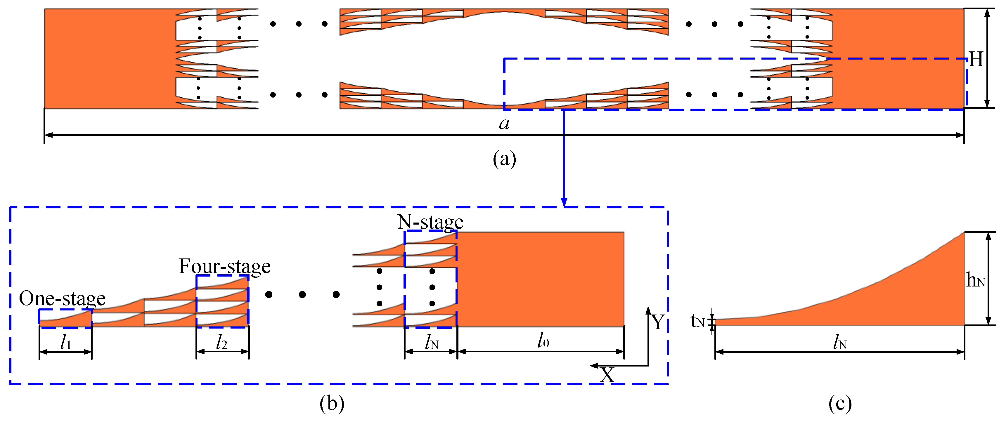
2.1. Structural Model
The unit cell of the SDM-ABH metamaterial presented in this paper is shown in Figure 1a, with the lattice constant and the height . The 1/4 structure of the single cell of the SDM-ABH metamaterial is shown in Figure 1b, in which the uniform beam region length is mm. The ABH region is composed of the N-stage ABH composite structure periodically arranged along the x-direction, and the Nth stage consists of N identical sub-ABHs arranged periodically along the y-direction, where the structural dimensions of the sub-ABHs are shown in Figure 1c, with length and truncated thickness . The variation in the thickness of the sub-ABHs satisfies the following relationship:
where the constant scale factor and the rational power exponent . The design and implementation of a functionally graded acoustic black hole based on metal additive manufacturing [20]. The SDM-ABH metamaterial also uses this manufacturing method, wherein the material is steel and the parameters are Young’s modulus , density , and Poisson’s ratio
2.2. Calculation of the Complex Energy Band
Complex energy bands can express the behaviour of evanescent waves that exist due to phenomena such as scattering and diffraction at the interface of metamaterials [27,28]. In this paper, the complex energy bands are calculated based on the partial differential equation module in the form of coefficients of Comsol 6.0 finite element software to explain the propagation behaviours of propagatable and evanescent waves [29,30]. The SDM-ABH metamaterial model proposed in this paper satisfies the isotropic, linear elastic, and homogeneous medium conditions and also satisfies the source term and undamped passive conditions, and therefore, the Bloch fluctuation equation is [31]:
In Equation (2), represents the material elasticity tensor, represents the mass density tensor, represents the position vector, represents the displacement vector, represents the double-point product, and represents the time variable. The partial differential modular control equation in coefficient form is [29]:
In Equation (3), represents the eigenvalue, represents the mass term, represents the damping term, represents the differential operator, represents the diffusion term, represents the conserved flux convective term, represents the conserved flux source term, represents the convective term, represents the absorbing term, represents the source term, and represents the eigenmode. Due to the periodicity of the metamaterial structures, by Bloch’s theorem of waves in structures, the outer boundaries of unit cells and wave fields are as follows:
In Equations (4) and (5), represents the wave vector, represents the unit cell lattice constant, represents the periodic function, and represents the eigenmode. Substituting Bloch theory Equations (4) and (5) into Equation (1) leads to [32]:
For a unit cell composed of isotropic materials, simple harmonic vibrations are considered to obtain [33]:
A partial differential module is used to solve for the mixed-mode energy band structure with wave numbers as eigenvalues, whose eigenvalues are taken as , and then , , , , and in Equation (3) are solved for the following, respectively:
In Equations (8)–(12), according to the steel material properties, is the first Lamey constant, which takes the value of 102 GPa, and is the second Lamey constant, which takes the value of 80 GPa. In the finite element analysis, the maximum mesh unit size is 0.0014, which is much smaller than one tenth of the elastic wave length, in order to ensure the correctness of the simulation. Sweeping ω in the range of 0–2000 Hz results in a complex wave vector k, which is referred to in this way as k(ω). The real wave vector and frequency represent the dispersion relationship of the real part of the complex energy band, and the negative wave vector and frequency represent the attenuation properties of evanescent wave (non-propagating) in the imaginary part of the complex energy band [34].
3. Calculation Results and Discussion
3.1. Complex Energy Band Structure and Vibration Modes
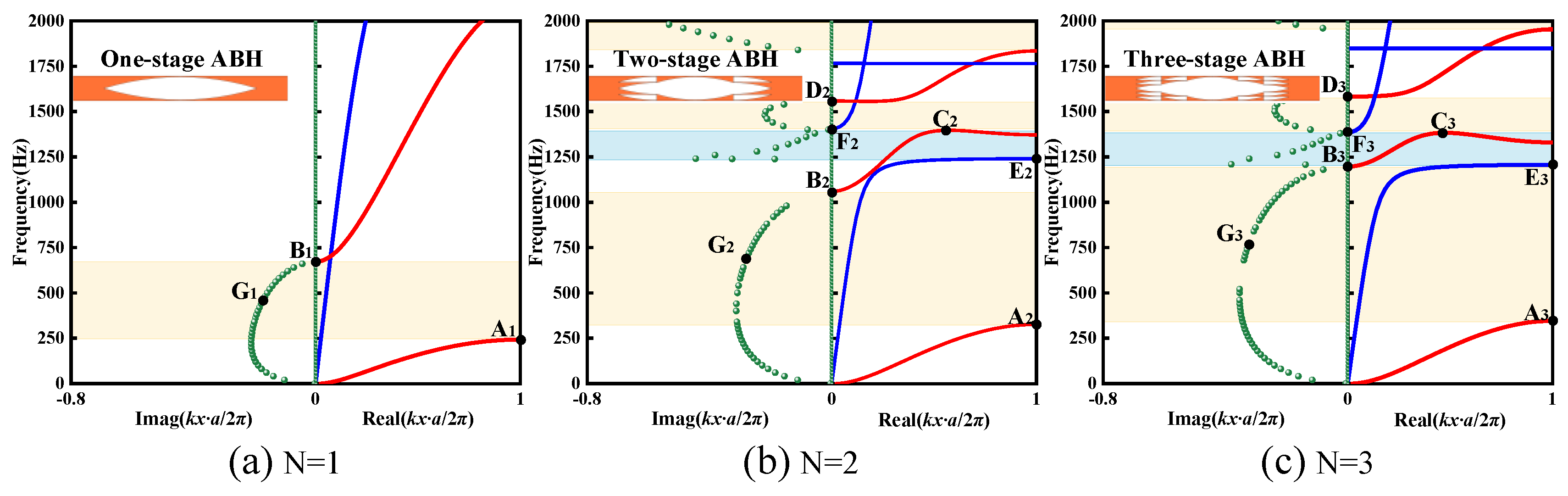
The partial differential equation module of the coefficient form of the finite element software is calculated. In theory, due to the complexity of the calculation, the material model satisfies the finite conditions such as the isotropy, linear elasticity, and homogeneity of media in order to simplify the calculation. However, these conditions are usually not satisfied for real materials. Therefore, the further influence of these conditions on material properties should be further analysed in practical engineering applications. The complex energy band structures of the SDM-ABH are shown in Figure 2a–c when N = 1, 2, and 3, respectively.
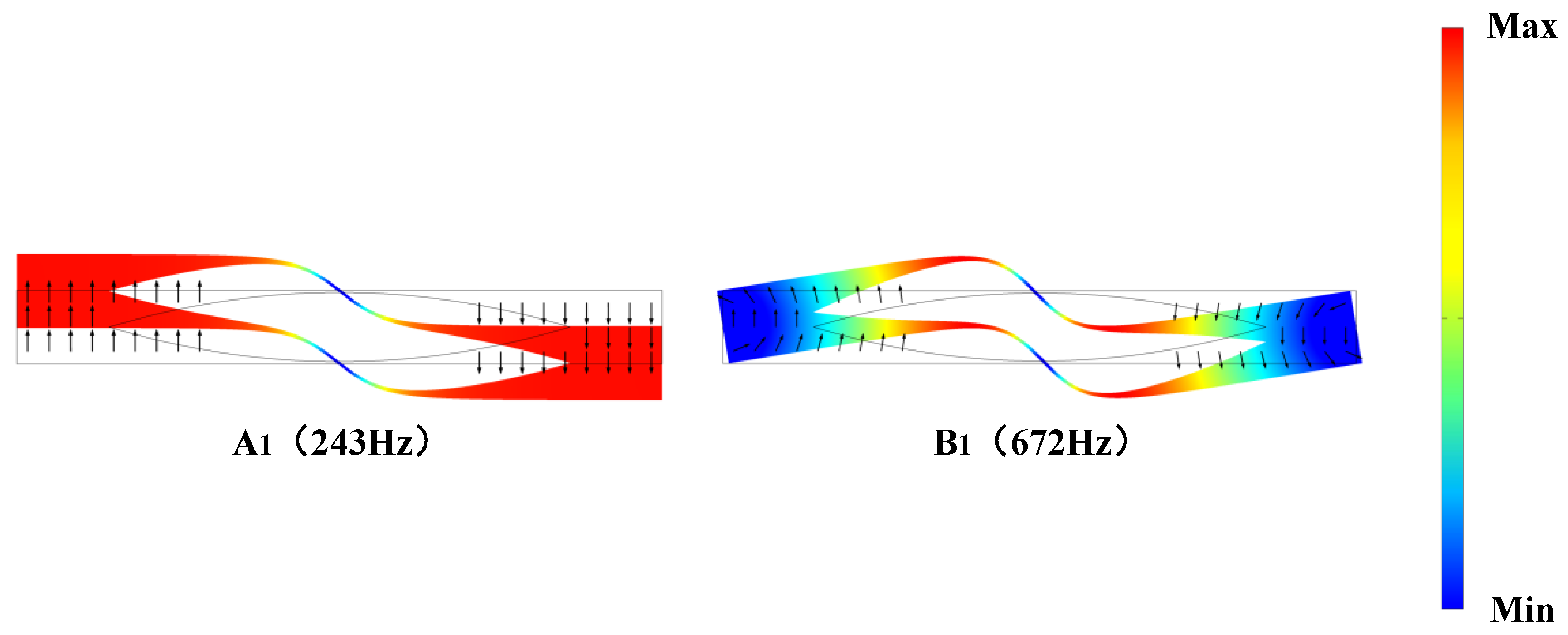
Observing the complex energy band structure of the SD1-ABH metamaterial in Figure 2a, it is found that there are three dispersion curves in the real part of the complex energy band in the range of 0–2000 Hz, and only one flexural wave bandgap (243 Hz–672 Hz) is generated, with a generalised width of [35], and the bandgap percentage is 21%. For studying the band gap formation mechanism of SD1-ABH metamaterials, the special point vibration modes of the real part of the curve in the complex energy band are calculated, as shown in Figure 3. Observing Figure 3, it is found that the vibrational modes at point A1 (243 Hz) of the initial frequency of the first flexural wave are concentrated in the uniform beams on two sides of the cell and the non-tip area of the first stage ABH, and the whole region presents local antisymmetric flexural vibration, and at this time, the first bandgap is opened. The vibrational modes at point B1 (672 Hz) at the cut-off frequency of the bandgap of the first flexural wave presents local torsional vibrational modes, and the Bloch wave in the periodic structure couples to the local resonance modes making the energy localised in the ABH mid-region, which hinders the propagation of the elastic wave; in addition, the two sides of the structure show torsional vibration modes with smaller displacements, which is due to the complex multiple elastic scattering phenomenon of the wave in the structure that starts to show between the periodic structures [36]. Observation of the imaginary part of the complex energy band in Figure 2a reveals the existence of an asymmetric semicircular arc with smooth frequency variation starting at 0 Hz, which is a typical feature of the coupling of local resonance and Bragg scattering [37]. Thus, the first flexural wave band gap of the SD1-ABH metamaterial is generated by the coupling of local resonance and Bragg scattering. In addition, there is a part of semicircular arc in the imaginary part of the complex energy band exists outside the bandgap, which belongs to the non-zero order diffraction wave. At the same time, the evanescent wave of swift to propagatable wave is realised at the cut-off frequency B1 point [29].
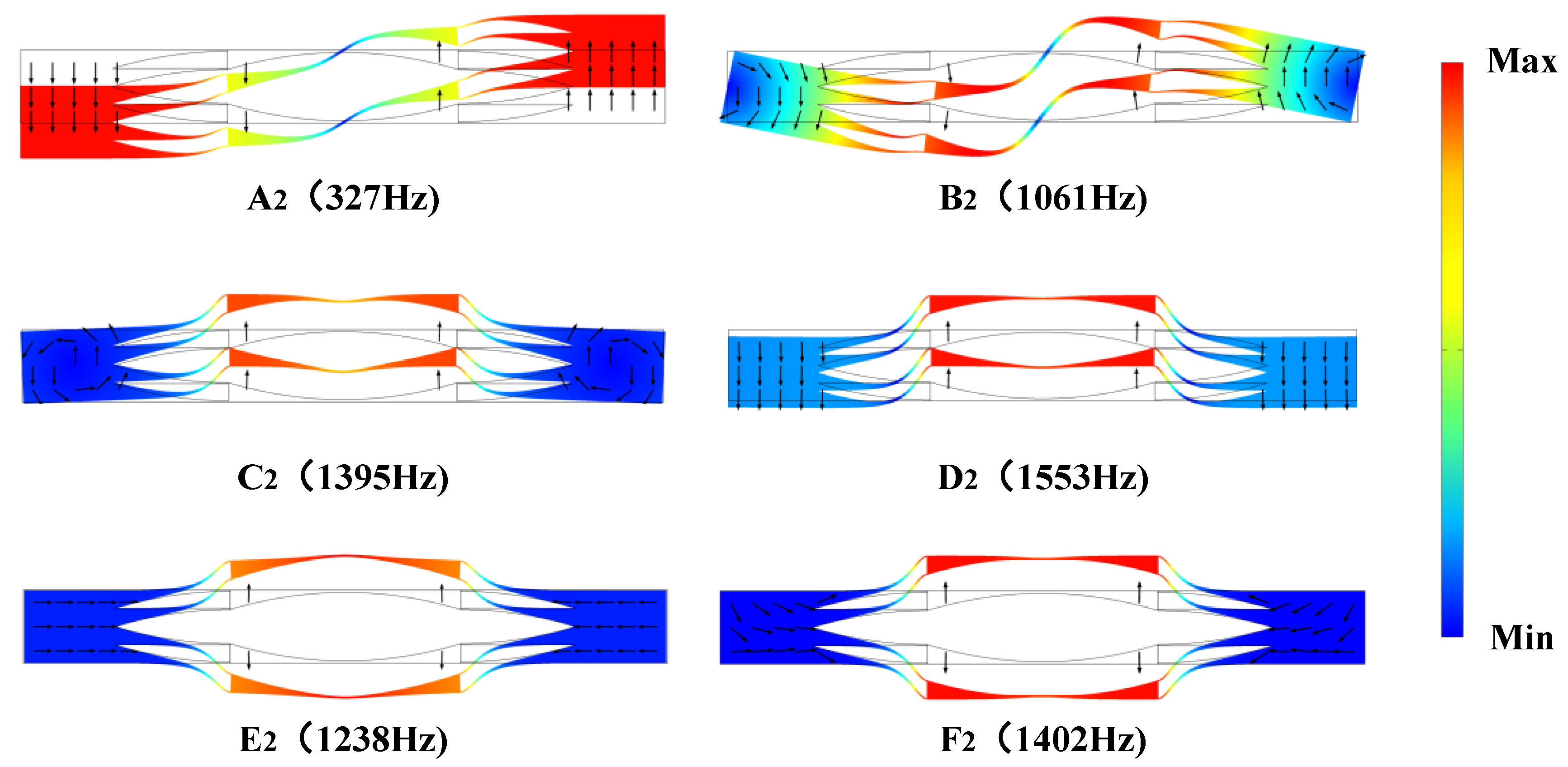
The structure is SD2-ABH metamaterial when N = 2, and the complex energy band structure is shown in Figure 2b. Observing the real part of the complex energy band in Figure 2b, it is found that there are six dispersion curves below 2000 Hz, forming three flexural bandgaps as well as one longitudinal bandgap. Among them are the following: the first flexural wave bandgap (327–1061 Hz), with a generalised width of the bandgap is ; the second flexural wave bandgap (1395–1553 Hz), with a generalised width of ; the third flexural wave bandgap (1832–2000 Hz), with a generalised width of ; and the first longitudinal wave bandgap (1238–1402 Hz), with a generalised width of . At this time, in the 0–2000 Hz range, the percentage of SD2-ABH metamaterials in the bandgap is increased to 60.9%, while their weights are 10% lighter than those of SD1-ABH metamaterials. For analysing the formation mechanism of the SD2-ABH metamaterial bandgap, the vibrational modes at special points of the real part of the curve in the complex energy band of Figure 2 are calculated, as shown in Figure 4. It is found that the vibrational modes at the point A2 (327 Hz), the initial frequency of the first flexural wave bandgap, also present local antisymmetric flexural modes, and it is found that the vibrational modes at the point B2 (1061 Hz) at the cut-off frequency are mainly concentrated in the non-tip region of the first-stage ABH, whereas all the sub-ABHs of the second-stage show energy aggregation, which at this time presents the coupling of local resonance modes and the ABH effect. Moreover, the torsional vibrational displacements of the two sides of the unit cell are larger, and the complex multiple elastic scattering phenomenon begins to intensify. Observing the imaginary part of the complex energy band in Figure 2b, it is found that the semicircular arc of the imaginary part corresponding to the first flexural wave bandgap still exhibits the typical shape characteristics of local resonance and Bragg scattering coupling [37]. Thus, the first flexural wave bandgap of the SD2-ABH metamaterials is generated by a complex coupling of ABH effect, local resonance, and Bragg scattering. The vibration modes of the initial frequency point C2 (1395 Hz) and the cut-off frequency point D2 (1553 Hz) of the second flexural wave bandgap are focused on the whole region of the first-stage ABH of the cell, which show the local in-phase vibration modes. In addition, the both unit cells of the C2 point also produce small torsional vibration, showing multiple elastic scattering phenomena, so the second flexural wave bandgap also indicates the typical properties of local resonance and Bragg scattering coupling [37]. For the longitudinal wave bandgap starting and stopping frequencies for the points E2 (1238 Hz) and F2 (1402 Hz), respectively, the vibrational modes are centrally distributed in the whole region of the first-stage ABH of the single cell due to the compression of the two sides of the single cell in the one-dimensional x-direction, which show local outward anti-phase vibration modes. Therefore, observing the imaginary part of the complex energy band in Figure 2b, the evanescent wave attenuation region corresponding to the first longitudinal wave bandgap shows a sharp tip shape, and the attenuation undergoes an abrupt change process, which is characteristic of the local resonance mechanism [38].
The structure is SD3-ABH metamaterial when N = 3, and the complex energy band structure is shown in Figure 2c. Observing the real part of the complex energy band in Figure 2c, there are three flexural wave bandgaps (346–1197 Hz, 1383–1584 Hz, and 1954–2000 Hz) and one longitudinal wave bandgap (1207–1386 Hz) in 0–2000 Hz. In this situation, the bandgap percentage increases to 63.7% and the weight is reduced by 13% compared with the SD1-ABH metamaterial. The vibration modes of special points in the real part curve of the complex energy band in Figure 2c are calculated, as shown in Figure 5. The vibration mode at the initial frequency A3 (346 Hz) of the first flexural bandgap also presents a local resonance mode. At the cut-off frequency point B3 (1197 Hz), the vibration mode is mainly distributed in the whole region of the second-stage ABH, and all the sub-ABHs of the third-stage show an ABH effect. Observing the imaginary part of the complex energy band in Figure 2c, the semicircular arc of the imaginary part corresponding to the first flexural band gap also appears smooth and asymmetric. Therefore, the first flexural wave band gap is also produced by the complex coupling of local resonance and Bragg scattering and shows an ABH effect. The initial frequency point C3 (1383 Hz) and the cut-off frequency point D3 (1584 Hz) of the second flexural band gap, the vibrational modes show a “swing” vibration pattern dominated by the ABH area of the first stage. And the imaginary part of the complex energy band of the second flexural band gap in Figure 2c is also smooth and asymmetric [37], and it is the coupling mechanism of the local resonance and the Bragg scattering. The E3 (1207 Hz) and F3 (1386 Hz) vibration modes at the starting and stopping frequency points of the first longitudinal wave bandgap show local inward inverted-phase vibration modes due to the stretching of the single cell in the one-dimensional x-direction, which are characteristic of the local resonance mechanism [39].
Further, by comparing the size of the semicircular arc of the imaginary part of the complex energy band in Figure 2a–c, it is found that the size of the semicircular arc of the imaginary part corresponding to the first flexural wave bandgap increases gradually with the increase in the number of stages N, indicating that the attenuation intensity of the first flexural wave bandgap increases gradually [40]. For investigating the attenuation enhancement mechanism of the elastic wave within the band gap, the evanescent modes at special points in the imaginary part of the complex energy bands of Figure 2a–c are computed, respectively, as shown in Figure 6. Observing the evanescent mode at point G1, the maximum vibrational displacement is located at the tip of the non-ABH, and no ABH effect occurs at this time. While for the evanescent mode at point G2, the maximum vibrational displacement of the second-stage ABHs is concentrated at the tips of multiple sub-ABHs, which generates multiple ABH effects. For the evanescent mode at point G3, vibrational aggregation exists at the tips of multiple sub-ABHs at the third-stage ABHs and at the tips of some of the second-stage ABHs, and the number of sub-ABHs producing the ABH effect is significantly increased. Therefore, for SDM-ABH metamaterials, as the number of stages increases, the number of sub-ABH structures exhibiting ABH effects increases, resulting in a substantial increase in the attenuation strength of the first flexural wave bandgap.
In this paper, the SDM-ABH metamaterial structures are compared with the previously structures, while the structures have similar lattice constants and the same material properties between them, as shown in Table 1. The comparison reveals that SD2-ABH and SD3-ABH metamaterials have ultra-wide first flexural wave bandgap with generalised widths of and , respectively, which are also superior to the other two structures of Table 1. This is of great significance for broadening the low-frequency damping.
3.2. Vibration Transmission and Vibration Displacement Field
The complex energy band structure is computed from the metamaterial with infinite periodic construction, and there is no propagatable wave in the bandgap. However, in practical applications, the metamaterial consists of finite periodic structure, and the propagatable wave in the bandgap is suppressed [41]. Considering the practical application, as in Figure 7a, a metamaterial consisting of 12 unit cells is used to apply flexural wave excitation along the y-direction and longitudinal wave excitation along the x-direction at the specified boundary on the left side, respectively, to pick up the displacement response on the rightmost side. Also, disregarding the influence of reflected waves on its results, a perfect matching layer is added on each side to better characterise the attenuation of the propagatable waves. The displacement frequency response function is calculated as follows:
In Equation (13), and are the pickup displacement and excitation displacement, respectively. In addition, for the calculation of the displacement frequency response function, a dense meshing is used, and in order to ensure that the structure has the maximum degree of freedom, the maximum mesh unit size is set to 0.0252, which is also much smaller than one tenth of the elastic wave length. The frequency response functions of the flexural and longitudinal waves of the finite-period construction at N = 1, 2, and 3 were calculated using the displacement transfer rate, as shown in Figure 7b–d, respectively. Observing Figure 7, it is found that the suppressed range of propagable waves in the finite- period structure is basically consistent with the band gap in the complex energy band structure in Figure 2. Further observation of Figure 7 reveals that the width of the first flexural wave bandgap of the three structures increases dramatically with the increase in the number of stages. And the maximum attenuation within the bandgap increases to 1.4 and 1.6 times more than that of the SD1-ABH metamaterials (89 dB), respectively, due to the increase in the number of sub-ABHs presenting an ABH effect.
The vibrational displacement field within the band gap of the first flexural wave of the first period in Figure 7a is calculated when N = 1, 2, and 3, as shown in Figure 8a–c, respectively. As can be observed in Figure 8, it is found that the vibrational displacement of the flexural wave at the frequency within the bandgap attenuation from the excitation value of 1 m to 0.443 m, 0.341 m, and 0.295 m occurs, respectively, when N = 1, 2, and 3. In Figure 8b, the SD2-ABH metamaterial undergoes a mutation at the tip of the second-stage ABH due to the ABH effect displacement attenuation. In Figure 8c, the SD3-ABH metamaterial undergoes a mutation at the tip of the third-stage ABH hole and at the tip of the second-stage ABH due to the ABH effect displacement attenuation.
4. Discussion of Geometric Parameter on Complex Band Structure
4.1. Effect of Truncated Thickness t on Band Gap
The truncated thickness t is an important structural parameter for acoustic black holes. Keeping other parameters constant, the effect of t on the first flexural wave bandgap characteristics of an SD2-ABH metamaterial is investigated, as shown in Figure 9. Observing Figure 9, it is found that the first flexural wave band gap initial frequency increases gradually with the increase in t, which is caused by the increase in structural stiffness because of the increase in t. The cut-off frequency of the first flexural wave band gap firstly increases and then decreases with the increase in t, and the maximum value is when the truncated thickness t = 2 mm. The band structure diagram in the real part of the complex energy band and the vibrational modes at the cut-off frequency of SD2-ABH metamaterials with different truncation thicknesses are calculated, respectively, as shown in Figure 10. Observing the vibration modes at the cut-off frequency of the first bending band gap in Figure 10, it is found that when t < 2 mm, the effect of ABH in the structure gradually decreases with the increase in t, and thus, the cut-off frequency moves to the high frequency. When t ≥ 2 mm, the ABH effect disappears, and the vibration modes change to the local resonance of the whole region of the first-stage ABH. Because of the increase in truncation thickness t, the resonance mass of the whole region of the first-stage ABH increases, and the cut-off frequency decreases. As a result, the first flexural wave band gap bandwidth firstly increases and secondly decreases with the truncation thickness t.
The effect of truncation thickness t on the first flexural wave bandgap characteristics of SD3-ABH metamaterials is shown in Figure 11. Figure 11 reveals that the same variation trend as that of the SD2-ABH metamaterial is presented. The special point vibrational modal analysis of the real part of the complex energy band is further calculated as shown in Figure 12. Observing Figure 12, it is found that for SD3-ABH metamaterials, the stiffness increases with the increase in t, leading to a gradual increase in the initial frequency of the first flexural bandgap; the vibrational modes at the cut-off frequency of the first flexural bandgap change from the coupling of the local resonance and the ABH effect to the local resonance modes in the overall region of the first-stage ABH in the same way.
4.2. Effect of Power Exponent on Bandgap
When N = 2 and 3, other parameters are kept constant, and the variation in the first flexural bandgap with power exponent m is shown in Figure 13a and Figure 13b, respectively. Observing Figure 13, it is found that the beginning and stopping frequencies of the first flexural bandgap of both single-phase double-leaf two-stage and three-stage ABH metamaterials decrease with the increase in power exponent m. This is due to the decrease in the local resonance stiffness with the increase in m. The cut-off frequencies of the first bandgap of both structures move faster to the lower frequencies with the increase in m. This is because the enhancement of the power exponent increases the ABH effect which is coupled with the local resonance and moves further to the lower frequency.
5. Interface Frequency Response
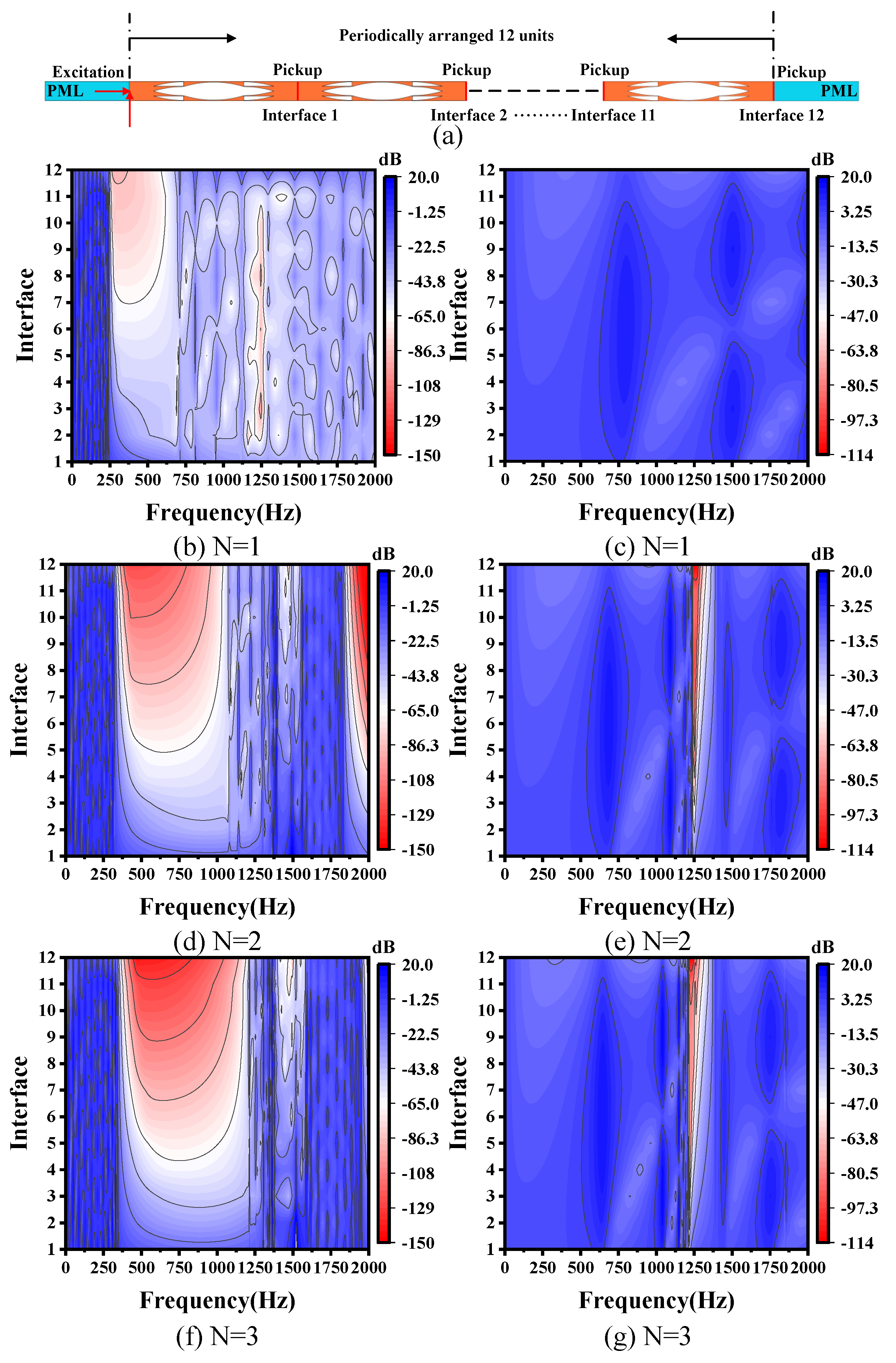
The trapped wave regions of flexural and longitudinal waves through different interfaces of SDM-ABH metamaterials consisting of 12 periods are calculated when N = 1, 2, and 3, as Figure 14 shows. Figure 14b,d,f represent the frequency response of the flexural wave interface at different numbers of stages, and it is observed that the SDM-ABH metamaterials can form an obvious flexural wave trapping region with the increase in the number of stages; at the same time, the flexural wave trapping effect can be achieved by reducing the number of unit cells and increasing the number of stages. In addition, Figure 14c,e,f represent the longitudinal wave interface frequency response at different stages, and it is found that the SD1-ABH metamaterials do not produce longitudinal wave trap region below 2000 Hz, but the SD2-ABH and SD3-ABH metamaterials can produce a longitudinal trap region below 2000 Hz, and the trap region moves to lower frequencies with the increase in the number of stages.
6. Conclusions
In this paper, the finite element method is applied to calculate the complex energy band structure and the vibrational modes of the special points in the real part of the complex energy band of single-phase double-leaf multi-stage acoustic black hole (SDM-ABH) metamaterials, to explore the mechanism of the generation of the low-frequency wide bandgap, and then the reasons for the enhancement of the low-frequency bandgap attenuation are revealed by the vibrational modes. Finally, vibrational transmission, and vibrational displacement fields of the special points in the imaginary part of the complex energy band, and the effects of the structural parameters on the characteristics of the bandgap, as well as the effects of the number of stages on the trapped region, are discussed.
(1) The finite element method is applied to calculate the complex energy band structure of SDM-ABH metamaterials, and it is found that in the range below 2000 HZ, compared with the conventional double-leaf acoustic black hole metamaterials (with a bandgap share of 21%), the single-phase double-leaf two-grade acoustic black hole (SD2-ABH) metamaterials can widen the bandgap percentage to 60.9% with a mass reduction of 10%, and single-phase double-leaf three-grade acoustic black hole (SD3-ABH) metamaterials widen the bandgap percentage to 63.7% with a mass reduction of 13%. And the maximum attenuation in the first flexural wave bandgap of SD2-ABH and SD3-ABH increases to 1.4 and 1.6 times, respectively, compared with the conventional double-leaf acoustic black hole metamaterials.
(2) By calculating the vibrational modes at special points in the real part of the complex energy band, it is found that an increase in the amount of stages causes an increase in the amount of sub-ABH structures in which the ABH effect occurs, although the mass decreases, which results in a significant increase in the width and attenuation of the first flexural bandgap. Moreover, an increase in the number of stages causes the emergence of the second flexural and longitudinal wave bandgaps. Further, the vibrational modes at special points and the vibrational displacement fields at special frequencies in the imaginary part of the complex energy band indicate that the phenomena of displacement aggregation and displacement mutation have occurred at several sub-ABHs of the SDM-ABH metamaterial.
(3) In addition, the effects of the ABH truncation thickness t and power exponent m on the band gap of the first flexural wave are investigated. With the increase in the truncation thickness t, the ABH effect of the sub-ABHs is gradually weakened, resulting in the first flexural wave cut-off frequency moving faster to high frequencies, and the ABH effect disappears when t > 2 mm, resulting in the first flexural wave cut-off frequency moving to low frequencies. In addition, as the power exponent m increases, the ABH effect of the sub-ABHs increases and the local resonance stiffness decreases, resulting in the first flexural wave bandgap moving to lower frequencies. Finally, the interfacial frequency response was calculated, and it is found that the trapping effect of SDM-ABH metamaterial on elastic waves gradually increased with the increase in the number of stages.
This study extends the study of ABH structures to the field of multi-stage metamaterials. Through this study, we can obtain a low-frequency as well as wide bandgap with strong attenuation and lightweight, making it potentially useful for lightweight vibration and noise reduction applications. Meanwhile, the single-phase multi-stage acoustic black hole structure provides some relevant guidance for the subsequent reduction in ABH truncated reflections.
Author Contributions
Conceptualization, methodology, software, validation, writing—original draft preparation, formal analysis, L.L. and S.J., Writing—review and editing, L.L., J.B., K.S., H.H. and L.Z., Supervision, funding acquisition, L.L. All authors have read and agreed to the published version of the manuscript.
Funding
This research was funded by the Natural Science Foundation of China under Grant No. 51405368, and the Natural Science Foundation of China Shaanxi Province under Grant No. 2017JM5024.
Institutional Review Board Statement
Not applicable.
Informed Consent Statement
Not applicable.
Data Availability Statement
The raw data supporting the conclusions of this article will be made available by the authors on request.
Conflicts of Interest
The authors declare no conflicts of interest.
References
- Yu, X.L.; Zhou, J. Mechanical metamaterials: Architected materials and unexplored properties. Mater. China 2019, 38, 14–21. [Google Scholar]
- Fang, X.; Wen, J.; Cheng, L.; Yu, D.; Zhang, H.; Gumbsch, P. Programmable gear-based mechanical metamaterials. Nat. Mater. 2022, 21, 869–876. [Google Scholar] [CrossRef] [PubMed]
- Yuan, M.; Cao, Z.; Luo, J.; Pang, Z. Helix structure for low frequency acoustic energy harvesting. Rev. Sci. Instrum. 2018, 89, 055002. [Google Scholar] [CrossRef]
- Li, L.; Su, K.; Liu, H.; Yang, Q.; Li, L.; Xie, M. Elastic metasurface for flexural wave refraction based on acoustic black hole. J. Appl. Phys. 2023, 133, 105103. [Google Scholar] [CrossRef]
- Yin, J.F.; Cai, L.; Fang, X.; Xiao, Y.; Yang, H.B.; Zhang, H.J.; Zhong, J.; Zhao, H.G.; Yu, D.L.; Wen, J.H. Review on research progress of mechanical metamaterials and their applications in vibration and noise control. Adv. Mech. 2022, 52, 508–586. [Google Scholar]
- Mironov, M. Propagation of a flexural wave in a plate whose thickness decreases smoothly to zero in a finite interval. Sov. Phys. Acoust. 1988, 34, 318–319. [Google Scholar]
- Krylov, V.; Tilman, F. Acoustic ‘black holes’ for flexural waves as effective vibration dampers. J. Sound Vib. 2003, 274, 605–619. [Google Scholar] [CrossRef]
- O’Boy, D.J.; Bowyer, E.P.; Krylov, V.V. Point mobility of a cylindrical plate incorporating a tapered hole of power-law profile. J. Acoust. Soc. Am. 2011, 129, 3475–3482. [Google Scholar] [CrossRef] [PubMed]
- Krylov, V.V. On the velocities of localized vibration modes in immersed solid wedges. J. Acoust. Soc. Am. 1998, 103, 767–770. [Google Scholar] [CrossRef]
- Krylov, V.V. New type of vibration dampers utilising the effect of acoustic ‘black holes’. Acta Acust. United Acust. 2004, 90, 830–837. [Google Scholar]
- O’Boy, D.J.; Krylov, V.V.; Kralovic, V. Damping of flexural vibrations in rectangular plates using the acoustic black hole effect. J. Sound Vib. 2010, 329, 4672–4688. [Google Scholar] [CrossRef]
- Zhao, L.; Semperlotti, F. Embedded acoustic black holes for semi-passive broadband vibration attenuation in thin-walled structures. J. Sound Vib. 2017, 388, 42–52. [Google Scholar] [CrossRef]
- Tang, L.; Cheng, L. Broadband locally resonant band gaps in periodic beam structures with embedded acoustic black holes. J. Appl. Phys. 2017, 121, 194901. [Google Scholar] [CrossRef]
- Tang, L.; Cheng, L. Ultrawide band gaps in beams with double-leaf acoustic black hole indentations. J. Acoust. Soc. Am. 2017, 142, 2802–2807. [Google Scholar] [CrossRef] [PubMed]
- Gao, N.; Wei, Z.; Zhang, R.; Hou, H. Low-frequency elastic wave attenuation in a composite acoustic black hole beam. Appl. Acoust. 2019, 154, 68–76. [Google Scholar] [CrossRef]
- Lyu, X.; Ding, Q.; Yang, T. Merging phononic crystals and acoustic black holes. Appl. Math. Mech. 2020, 41, 279–288. [Google Scholar] [CrossRef]
- Deng, J.; Guasch, O.; Maxit, L.; Gao, N. A metamaterial consisting of an acoustic black hole plate with local resonators for broadband vibration reduction. J. Sound Vib. 2022, 526, 116803. [Google Scholar] [CrossRef]
- Ji, H.; Han, B.; Cheng, L.; Inman, D.J.; Qiu, J. Frequency attenuation band with low vibration transmission in a finite-size plate strip embedded with 2D acoustic black holes. Mech. Syst. Signal Process. 2022, 163, 108149. [Google Scholar] [CrossRef]
- Sheng, H.; He, M.X.; Ding, Q. Vibration suppression by mistuning acoustic black hole dynamic vibration absorbers. J. Sound Vib. 2023, 542, 117370. [Google Scholar] [CrossRef]
- Sheng, H.; He, M.X.; Lyu, X.F.; Ding, Q. Ultra-low frequency broadband gap optimization of 1D periodic structure with dual power-law acoustic black holes. J. Intell. Mater. Syst. Struct. 2022, 33, 532–546. [Google Scholar] [CrossRef]
- He, C.; Lim, K.M.; Zhang, F. A novel periodic beam with multilayer acoustic black holes for deep sub-wavelength vibration attenuation. Acta Mech. 2023, 234, 2585–2598. [Google Scholar] [CrossRef]
- Huang, H.H.; Sun, C.T.; Huang, G.L. On the negative effective mass density in acoustic metamaterials. Int. J. Eng. Sci. 2009, 47, 610–617. [Google Scholar] [CrossRef]
- Huang, G.L.; Sun, C.T. Band Gaps in a Multiresonator Acoustic Metamaterial. J. Vib. Acoust. 2010, 031003. [Google Scholar] [CrossRef]
- Song, G.Y.; Cheng, Q.; Huang, B.; Dong, H.Y.; Cui, T.J. Broadband fractal acoustic metamaterials for low-frequency sound attenuation. Appl. Phys. Lett. 2016, 109, 131901. [Google Scholar] [CrossRef]
- Li, L.; Lv, R.; Cai, A.; Xie, M.; Chen, Y.; Huang, G. Low-frequency vibration suppression of a multi-layered elastic metamaterial shaft with discretized scatters. J. Phys. D Appl. Phys. 2018, 52, 055105. [Google Scholar] [CrossRef]
- Gorshkov, V.; Sareh, P.; Navadeh, N.; Tereshchuk, V.; Fallah, A.S. Multi-resonator metamaterials as multi-band metastructures. Mater. Des. 2021, 202, 109522. [Google Scholar] [CrossRef]
- Zhang, X.; Liu, Z.; Mei, J.; Liu, Y. Acoustic band gaps for a two-dimensional periodic array of solid cylinders in viscous liquid. J. Phys. Condens. Matter 2003, 15, 8207. [Google Scholar] [CrossRef]
- Oudich, M.; Badreddine Assouar, M. Complex band structures and evanescent Bloch waves in two-dimensional finite phononic plate. J. Appl. Phys. 2012, 112, 104509. [Google Scholar] [CrossRef]
- Laude, V.; Achaoui, Y.; Benchabane, S.; Khelif, A. Evanescent Bloch waves and the complex band structure of phononic crystals. Phys. Rev. B 2009, 80, 092301. [Google Scholar] [CrossRef]
- Bavencoffe, M.; Morvan, B.; Izbicki, J.L.; Hladky-Hennion, A.C. Characterization of evanescent ultrasonic waves in a band gap of a 1D phononic crystal. In Proceedings of the 2009 IEEE International Ultrasonics Symposium, Rome, Italy, 20–23 September 2009; pp. 1024–1027. [Google Scholar]
- Achaoui, Y.; Khelif, A.; Benchabane, S.; Robert, L.; Laude, V. Experimental observation of locally-resonant and Bragg band gaps for surface guided waves in a phononic crystal of pillars. Phys. Rev. B 2011, 83, 104201. [Google Scholar] [CrossRef]
- Zhou, X.Z.; Wang, Y.S.; Zhang, C. Effects of material parameters on elastic band gaps of two-dimensional solid phononic crystals. J. Appl. Phys. 2009, 106, 014903. [Google Scholar] [CrossRef]
- Yan, Z.Z.; Wang, Y.S. Wavelet-based method for calculating elastic band gaps of two-dimensional phononic crystals. Phys. Rev. B 2006, 74, 224303. [Google Scholar] [CrossRef]
- Veres, I.A.; Berer, T.; Matsuda, O. Complex band structures of two dimensional phononic crystals: Analysis by the finite element method. J. Appl. Phys. 2013, 114, 083519. [Google Scholar] [CrossRef]
- Fang, X.; Wen, J.; Bonello, B.; Yin, J.; Yu, D. Ultra-low and ultra-broad-band nonlinear acoustic metamaterials. Nat. Commun. 2017, 8, 1288. [Google Scholar] [CrossRef] [PubMed]
- Ho, K.M.; Cheng, C.K.; Yang, Z.; Zhang, X.X.; Sheng, P. Broadband locally resonant sonic shields. Appl. Phys. Lett. 2003, 83, 5566–5568. [Google Scholar] [CrossRef]
- Xiao, Y.; Mace, B.R.; Wen, J.; Wen, X. Formation and coupling of band gaps in a locally resonant elastic system comprising a string with attached resonators. Phys. Lett. A 2011, 375, 1485–1491. [Google Scholar] [CrossRef]
- Yu, D.; Liu, Y.; Wang, G.; Cai, L.; Qiu, J. Low frequency torsional vibration gaps in the shaft with locally resonant structures. Phys. Lett. A 2006, 348, 410–415. [Google Scholar] [CrossRef]
- Robillard, J.F.; Bucay, J.; Deymier, P.A.; Shelke, A.; Muralidharan, K.; Merheb, B.; Vasseur, J.O.; Sukhovich, A.; Page, J.H. Resolution limit of a phononic crystal superlens. Phys. Rev. B 2011, 83, 224301. [Google Scholar] [CrossRef]
- Wang, Y.F.; Wang, Y.S.; Laude, V. Wave propagation in two-dimensional viscoelastic metamaterials. Phys. Rev. B 2015, 92, 104110. [Google Scholar] [CrossRef]
- Wen, J.H.; Cai, L.; Yu, D.L.; Xiao, Y.; Zhao, H.G.; Yin, J.F.; Yang, H.B. Fundamental Theories and Applications of Acoustic Metamaterials; Science Press: Beijing, China, 2018. [Google Scholar]
Figure 1.
(a) SDM-ABH unit cell. (b) Enlarged view of 1/4 unit cell. (c) Sub-ABH.

Figure 2.
Complex energy band structure. (a) N = 1, i.e., single-phase double-leaf one-stage acoustic black hole (SD1-ABH) metamaterial. (b) N = 2, i.e., single-phase double-leaf two-stage acoustic black hole (SD2-ABH) metamaterial. (c) N = 3, i.e., single-phase double-leaf three-stage acoustic black hole (SD3-ABH) metamaterial. Red represents flexural wave dispersion curves and blue represents longitudinal wave dispersion curves.

Figure 3.
Vibration modal diagrams of special points in the real part of the complex energy band of SD1-ABH metamaterial, where the direction and length of each arrow indicate the direction and magnitude of the displacement of the medium at the starting point of the arrow, respectively.
Figure 3.
Vibration modal diagrams of special points in the real part of the complex energy band of SD1-ABH metamaterial, where the direction and length of each arrow indicate the direction and magnitude of the displacement of the medium at the starting point of the arrow, respectively.

Figure 4.
Vibration modal diagrams of special points in the real part of the complex energy band of SD2-ABH metamaterial, where the direction and length of each arrow indicate the direction and magnitude of the displacement of the medium at the starting point of the arrow, respectively.
Figure 4.
Vibration modal diagrams of special points in the real part of the complex energy band of SD2-ABH metamaterial, where the direction and length of each arrow indicate the direction and magnitude of the displacement of the medium at the starting point of the arrow, respectively.

Figure 5.
Vibration modal diagrams of special points in the real part of the complex energy band of SD3-ABH metamaterial, where the direction and length of each arrow indicate the direction and magnitude of the displacement of the medium at the starting point of the arrow, respectively.
Figure 5.
Vibration modal diagrams of special points in the real part of the complex energy band of SD3-ABH metamaterial, where the direction and length of each arrow indicate the direction and magnitude of the displacement of the medium at the starting point of the arrow, respectively.

Figure 6.
Evanescent mode diagrams of special points in the imaginary part of the complex energy band of the SDM-ABH metamaterial. (a) SD1-ABH metamaterial evanescent mode. (b) SD2-ABH metamaterial evanescent mode; (c) SD3-ABH metamaterial evanescent mode.
Figure 6.
Evanescent mode diagrams of special points in the imaginary part of the complex energy band of the SDM-ABH metamaterial. (a) SD1-ABH metamaterial evanescent mode. (b) SD2-ABH metamaterial evanescent mode; (c) SD3-ABH metamaterial evanescent mode.

Figure 7.
The process and results of vibration transmission: (a) Schematic diagram of vibration transmission of metamaterials composed of 12 unit cells; (b) N = 1 finite-period SD1-ABH metamaterial vibration transmission results; (c) N = 2 finite-period SD2-ABH metamaterial vibration transmission results; (d) N = 3 finite-period SD3-ABH metamaterial vibration transmission results. Red colour represents the flexural wave frequency response function and blue colour represents the longitudinal wave frequency response function.

Figure 8.
Vibration displacement field of the first period of the finite period construction: (a) represents the vibration displacement field at the frequency of 273 Hz in Figure 7b; (b) represents the vibration displacement field at the frequency of 411 Hz in Figure 7c; (c) represents the vibration displacement field at the frequency of 476 Hz in Figure 7d.

Figure 9.
Effect of truncation thickness t on the bandgap of the first flexural wave of an SD2-ABH metamaterial. Symbols indicate band gap boundaries and red coloured lines between symbols indicate band gap widths.
Figure 9.
Effect of truncation thickness t on the bandgap of the first flexural wave of an SD2-ABH metamaterial. Symbols indicate band gap boundaries and red coloured lines between symbols indicate band gap widths.

Figure 10.
Vibration modes of the real part of the complex energy band with different truncation thicknesses as well as special points.
Figure 10.
Vibration modes of the real part of the complex energy band with different truncation thicknesses as well as special points.

Figure 11.
Effect of truncation thickness t on the bandgap of the first flexural wave of an SD3-ABH metamaterial. Symbols indicate band gap boundaries and red coloured lines between symbols indicate band gap widths.
Figure 11.
Effect of truncation thickness t on the bandgap of the first flexural wave of an SD3-ABH metamaterial. Symbols indicate band gap boundaries and red coloured lines between symbols indicate band gap widths.

Figure 12.
Vibration modes of the real part of the complex energy band with different truncation thicknesses as well as special points.
Figure 12.
Vibration modes of the real part of the complex energy band with different truncation thicknesses as well as special points.

Figure 13.
Effect of power exponent m on the bandgap of the first flexural wave: (a) SD2-ABH metamaterial; (b) SD3-ABH metamaterial. Symbols indicate band gap boundaries and red coloured lines between symbols indicate band gap widths.
Figure 13.
Effect of power exponent m on the bandgap of the first flexural wave: (a) SD2-ABH metamaterial; (b) SD3-ABH metamaterial. Symbols indicate band gap boundaries and red coloured lines between symbols indicate band gap widths.

Figure 14.
Frequency response analysis of metamaterial interfaces consisting of 12 unit cells: (a) schematic diagram of the computational analysis of interfacial response of different cells; (b,d,f) represent the flexural wave trapping regions of different interfaces at N = 1, 2, and 3; (c,e,g) represent the longitudinal wave trapping regions of different interfaces at N = 1, 2, and 3. The red colour represents the trapped wave region.


Disclaimer/Publisher’s Note: The statements, opinions and data contained in all publications are solely those of the individual author(s) and contributor(s) and not of MDPI and/or the editor(s). MDPI and/or the editor(s) disclaim responsibility for any injury to people or property resulting from any ideas, methods, instructions or products referred to in the content. |
© 2024 by the authors. Licensee MDPI, Basel, Switzerland. This article is an open access article distributed under the terms and conditions of the Creative Commons Attribution (CC BY) license (https://creativecommons.org/licenses/by/4.0/).
Share and Cite
MDPI and ACS Style
Li, L.; Jiang, S.; Bai, J.; Su, K.; Hu, H.; Zhang, L. A Single-Phase Lightweight Double-Leaf Multi-Stage Acoustic Black Hole Model of Metamaterial. Appl. Sci. 2024, 14, 2875. https://doi.org/10.3390/app14072875
AMA Style
Li L, Jiang S, Bai J, Su K, Hu H, Zhang L. A Single-Phase Lightweight Double-Leaf Multi-Stage Acoustic Black Hole Model of Metamaterial. Applied Sciences. 2024; 14(7):2875. https://doi.org/10.3390/app14072875
Chicago/Turabian StyleLi, Lixia, Shanhe Jiang, Jin Bai, Kun Su, Haiteng Hu, and Lei Zhang. 2024. "A Single-Phase Lightweight Double-Leaf Multi-Stage Acoustic Black Hole Model of Metamaterial" Applied Sciences 14, no. 7: 2875. https://doi.org/10.3390/app14072875
Note that from the first issue of 2016, this journal uses article numbers instead of page numbers. See further details here.