
The Use of Ashes in Surface Metal Matrix Composites Produced by Friction Stir Processing


1
Department of Materials Engineering, Faculty of Production Engineering and Materials Technology, Czestochowa University of Technology, 19 Armii Krajowej Ave., 42-200 Czestochowa, Poland
2
Department of Technology and Automation, Faculty of Mechanical Engineering and Computer Science, Czestochowa University of Technology, 21 Armii Krajowej Ave., 42-200 Czestochowa, Poland
3
Faculty of Environmental and Energy Engineering, Silesian University of Technology, 18 Konarskiego Ave., 44-100 Gliwice, Poland
*
Author to whom correspondence should be addressed.
Appl. Sci. 2024, 14(9), 3544; https://doi.org/10.3390/app14093544
Submission received: 18 March 2024
/
Revised: 9 April 2024
/
Accepted: 20 April 2024
/
Published: 23 April 2024
(This article belongs to the Special Issue Mechanical and Electrical Properties of Composite Materials)
Abstract
:The article presents an assessment of the possibility of using ashes from the combustion of coal and biomass as a reinforcing phase in metal matrix composites. The composite surface layer was produced by means of the FSP (friction stir processing) method, using an original hole solution with a shifted working zone of the pin. The composite matrix was AA7075 alloy. The obtained composite was subjected to microscopic observations, tribological tests, and hardness measurements. The microscopic examinations revealed favorable changes in the microstructure, in particular, strong refinement of the grains, uniform distribution of the reinforcing phase, and good bonding of the particles of this phase with the matrix material. Changes in the microstructure resulted in a significant increase in the hardness (from 36 to 41% depending on the type of reinforcing phase) and wear resistance (from 24.1 to 32.9%), despite partial dissolution of the intermetallic phases. It was found that the effect of strengthening the matrix and the uniformity of the distribution of the reinforcing phase depend on the physicochemical properties of the used powders, especially on the shape and size of the particles. The research shows that the use of ashes as a reinforcing phase in composites is fully justified.
1. Introduction
Aluminum alloys are modern engineering materials used in many industries. The application potential of aluminum alloys results primarily from their low density and good strength properties. The density of aluminum is 2.7 g/cm3, which is only 34% of the density of iron. The strength-to-density ratio makes aluminum alloys an effective replacement for steel in industries such as transportation, aviation, and automobile production. High corrosion resistance, and good thermal and electrical conductivity, in addition to full recyclability, complement the characteristics of aluminum alloys and emphasize their versatility. Aluminum alloys are most commonly used in the aviation and automotive industries, but these materials are present in virtually every industry. What limits the application potential of these alloys is primarily their low hardness and resistance to abrasive wear. Therefore, various actions are taken to improve these properties. One such solution is to modify the surface layer. Inducing specific changes in the microstructure of the surface layer allows enhancement of its mechanical and tribological properties while maintaining a ductile core, which is particularly important in many applications. That is why surface engineering solutions enjoy unflagging interest. In addition to coating technology, concentrated heat sources are increasingly employed to melt the surface layer and induce rapid crystallization in the material [1,2,3].
A relatively new solution is modification of the surface layer using the modern FSP method. FSP technology was developed by R.S. Mishra et al. [4,5], although the essence of this method comes from the FSW technology developed in the early 1990s by W.M. Thomas from the Welding Institute (TWI) in Cambridge, UK [6], and is based on the same principles as FSP. The difference between FSW and FSP technology lies in the purpose of these methods. FSW technology is used to join materials [7,8,9,10,11], while FSP technology is used to modify the surface layer of materials [12,13,14,15,16]. In both technologies, the source of heat is the friction of a special tool against the surface of the modified material and the strong plastic deformation of the material [17]. The dimensions of the pin and shoulder, as well as their shape and surface profile, determine the amount of heat generated, the mixing efficiency, and material flow intensity, and, consequently, also determine the microstructural effects of the processing and the resulting properties of the surface layer, including the material hardness and wear resistance. When designing and constructing a tool, it should be remembered that as much as 80–90% of the heat generated when the tool rubs against the material surface is generated by the shoulder, and only 10–20% of this heat is generated as a result of the friction of the remaining surfaces of the tool against the material [18]. During processing, the melting point of the modified material is not exceeded, and all changes in the microstructure and properties of the material occur during one short technological operation, which makes the FSP method a unique technology in many respects. One of the significant advantages of FSP is the ability to produce composite surface layers. The first information about the use of the FSP method for the production of composites appeared in the works of the creators of this method [19]. The results presented by the authors of the paper initiated a new important trend and direction in the development of the FSP method and paved the way for further methodological solutions enabling the production of a wide range of composite surface layers with various chemical compositions and purposes [20,21,22,23,24].
To date, a number of solutions have been developed to effectively introduce the reinforcing phase into the metal matrix. The most popular solution is the groove method [25,26,27,28,29], but the chamber method [30,31,32] or, for example, the DFSP (direct friction stir processing) method [33,34] is also becoming progressively more popular. Each of these methods allows the introduction of the reinforcing material into the plasticized matrix material and the creation of a composite microstructure in it. Composite layers are also successfully produced in aluminum alloys in this way. SiC, Al2O3, and ZrO2 particles, but also, e.g., carbon nanotubes, are most often used as the reinforcing phase. The research results presented in the world literature, including the results of the authors’ own research, prove that in this way beneficial changes can be induced in the microstructure and properties of aluminum alloys [35,36,37,38]. In analyzing the literature data, it can also be noticed that attempts are being made to use waste materials as a reinforcing phase in the design of composites. Replacing typical reinforcing materials with waste materials not only allows effective waste management, but also contributes to reducing the total costs of composite production, and is also a pro-ecological activity, consistent with global trends in replacing materials and natural raw materials with waste. Therefore, such action is justified not only economically, but also ecologically.
The literature data indicate that attempts have already been made to use industrial waste or by-products generated in production processes to produce composites [39,40,41,42,43,44,45,46,47]. For this purpose, e.g., dust from power plants, rice husks rich in silicon, particles from snail shells, walnut powder, and ash obtained from peanut shells have been used.
Patil et al. [40] found, for example, that the use of fly ash for the production of metal matrix composites results in a significant increase in the hardness of the alloy, although this effect depends on the final share of this phase in the composite. The authors observed the greatest increase in hardness was with a 4% share of the reinforcing phase, while the introduction of a larger amount of the reinforcing phase (6 and 8%) was not as effective in increasing the hardness value due to the agglomeration of the micropowder and weak interfacial bonding.
Srivastava et al. [44] used eggshell to produce a surface composite based on AZ31B magnesium alloy. They used two types of reinforcement in the composite, namely, Si3N4 particles, which constituted the primary reinforcement, and chicken eggshell powder (ESP), which constituted the secondary reinforcement. In this way, an AZ31B/Si3N4/ESP composite was produced. The authors concluded that waste chicken eggshells provide a useful reinforcement to improve the mechanical and tribological properties of the magnesium alloy.
Dinaharan and Akinlabi [39] also obtained promising results. The authors used fly ash to produce composites based on the AA6061 aluminum alloy, AZ31 magnesium alloy, and copper. The composites were synthesized by means of friction stir processing. A uniform distribution of fly ash particles in the metal matrix was observed, which, according to the authors, is a result of the effective stirring action of the rotating tool. FSP treatment also caused refinement of the reinforcement phase particles, but it should be emphasized that the crushed remains of these particles also mixed well with the plasticized matrix material and formed a composite. A consequence of introducing the reinforcing phase into the composite matrix was an increase in the hardness of the material. An improvement in hardness was observed in all the composite samples.
The authors of work [45] produced a composite layer in the 7075-T651 aluminum alloy by means of the FSP method. They used fly ash from industrial waste mixed with silicon carbide particles. The main goal of the work was to improve the hardness and wear resistance of the alloy’s surface layer. The authors found that both the share of the reinforcing phase and the quantitative relationship between SiC and fly ash have the greatest impact on the wear rate and the microhardness of the composites. They also found that the uniformity of the SiC/fly ash reinforcement dispersion is the most important factor in improving the hardness and wear resistance of the composites.
Fly ash was also utilized by Prakasam et al. [46] to produce composites by means of the high-temperature vacuum stir casting technique. Metal matrix composites made of AA7075 aluminum alloy with 0 wt%, 6 wt%, and 12 wt% fly ash reinforcement were analyzed. The authors found that an increase in the fly ash content leads to a rise in the hardness of the composite. This hardness in the case of the composite containing 12 wt% fly ash was up to 28% higher than the hardness of the material not reinforced with fly ash. Also in the case of the tribological test, it was found that the composite containing the highest amount of fly ash had the best tribological properties.
The mechanical and wear properties of AA7075-T6 reinforced with SiC and aloe vera ash, fabricated using friction stir processing, were analyzed by Tyagi et al. [47]. To more precisely examine the behavior of the samples during wear tests, the authors used different loads, i.e., 20 N, 30 N, and 40 N. The tests revealed that the lowest resistance was observed in the non-composite sample, while the wear of the composite samples grew with the increment in the applied load. The authors noted the highest wear resistance of the samples in the case of the load of 20 N, which they explained by the formation of an oxide tribolayer that acted as a solid lubricant. The authors also found a lower coefficient of friction for the composite samples than for the aluminum alloy samples.
The examples discussed above demonstrate that waste materials have enormous potential, which, unfortunately, is not fully exploited.
The work attempts to use ashes from the combustion of fossil fuels and biomass as a reinforcing phase in metal matrix composites. The main emphasis in the research was placed on assessing the size and nature of changes in the microstructure and their impact on selected properties of the studied material, i.e., the hardness and wear resistance. The properties of the composite are a consequence not only of the properties of the components constituting the composite and their volume fractions, but also of changes occurring directly in the microstructure of the material.
2. Materials and Methods
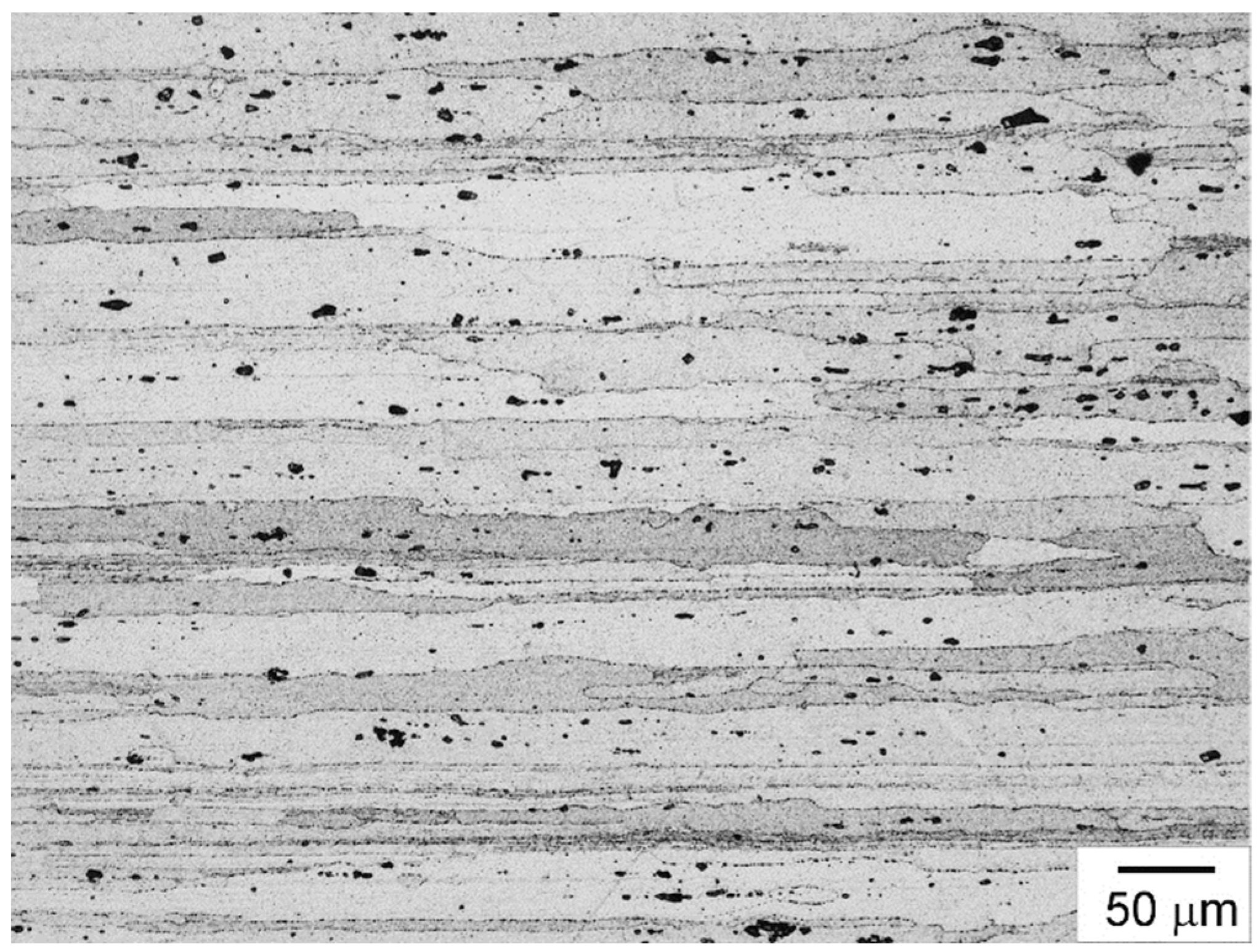
The matrix of the designed composite was the AA7075 aluminum alloy (Al-5.5Zn-2.4Mg-1.6Cu-0.20Cr) in the T6 condition (an alloy treated with a supersaturated solution and artificially aged). The samples had the shape of cuboids with the dimensions 100 × 70 × 15 mm (length × width × sample thickness). The chemical composition of the alloy is presented in Table 1, and an example microstructure is shown in Figure 1.
Microstructural investigations were carried out on cross sections perpendicular to the tool traverse direction. The metallographic specimens were etched with Keller’s reagent (2 mL HF + 3 mL HCl + 5 mL HNO3 + 190 mL distilled water). Microscopic examinations were performed using a Keyence VHX-7000 light microscope (Keyence Ltd., Osaka, Japan). The aluminum alloy had a typical rolling microstructure with highly elongated grains typical of rolled material, which reflected the rolling direction and gave it a banded feature. The average length of the grains of the α primary solution in the analyzed alloy was approximately 290 µm. Moreover, numerous precipitates of intermetallic phases were found in the alloy. These precipitates were located both inside the grains and at the grain boundaries of the solid solution. Identification of the chemical composition of the precipitates was carried out using an Oxford Instruments EDS microanalyzer (Oxford Instruments Plc., Abingdon, UK). These studies showed that the AA7075 alloy contains precipitates rich in Al, Zn, and Cu, but also precipitates containing Al, Fe, and Cu and less numerous phases rich in Al, Si, and Zn and Al, Zn, and Mg. Studies of the phases occurring in the AA7075 aluminum alloy were presented in a previous work [16].
Two ashes obtained in the process of coal and biomass combustion were used as the reinforcing phase. In the case of the ashes marked as A-1, the share of coal and biomass in the fuel was 70–90% in the case of coal and 10–30% in the case of biomass, respectively. These shares in the case of the second ash (marked as A-2) were as follows: 90–95% in the case of coal and 5–10% in the case of biomass. The chemical composition of the ashes is presented in Table 2. The chemical composition was determined by X-ray fluorescence spectroscopy.
SiC powder was also used to produce the composite. Technical SiC powder was utilized with an average particle size of approximately 20 µm and a polyhedral shape. The composite reinforced with SiC particles was the reference material in this work.
Important parameters characterizing each material used as a reinforcing phase in a composite are its physicochemical properties, especially the size, shape, and geometry of the surface. These properties result from the employed production technology, but also from the origin of the material. Too complex a shape and a highly developed geometric structure of the surface make it difficult to distribute the reinforcing phase in the composite matrix and to achieve an even distribution of such a phase in the matrix. In such a case, the risk of unfavorable clusters and agglomerates occurring in the composite also increases as a result of the mutual adhesion of neighboring particles with surface irregularities. The occurrence of agglomerates is often accompanied by material discontinuities. These discontinuities are usually located inside the agglomerates due to the inability or limited ability of the plasticized matrix to penetrate such a place. Therefore, in the process of designing composites and selecting the reinforcing phase, its physicochemical properties are also assessed. Such an analysis was also carried out as part of this work, and sample results of these studies are presented in Figure 2. The microstructure and morphology of the ashes were examined by scanning electron microscopy using a JEOL JSM-6610LV microscope (JEOL Ltd., Tokyo, Japan). The microscopic examinations revealed significant differences in the shape and morphology of the used powders. Two types of particles were found in the A-1 powder, namely, particles with a spheroidal shape and a small degree of surface development, but also particles with a polyhedral shape and dimensions clearly larger than the dominant spheroidal particles (Figure 2a,b). Powder A-2 was dominated by particles of an irregular shape and a complex geometric surface structure (Figure 2c,d). Nevertheless, particles of a more regular polyhedral shape with clearly marked cleavage planes were less numerous. A common feature of both the analyzed powders was the very large particle size dispersion. For the A-1 powder, the particle size ranged from tenths of a micrometer to over 100 µm, with particles ranging from 2 to 5 µm predominating. In turn, in the case of powder A-2, the particle size ranged from tenths of a micrometer to even 150 µm, with the dominant fraction being particles ranging from 1 µm to 7 µm.
Significant differences in the particle morphology occurring within a given type of powder may indicate the different chemical composition of these particles. To verify this, EDS analysis was carried out. Examples of the results of these studies are presented in Figure 3 and Figure 4 and summarized in Table 3 and Table 4.
Analyzing the EDS results of the A-1 powder, it can be noticed that the differences in the shape and morphology of the particles found during microscopic examination were also reflected in differences in their chemical composition. In the case of smaller particles characterized by a polyhedral shape, the EDS analysis revealed the presence of silicon and oxygen, which proves that these particles are silica. This statement is also confirmed by the characteristic shape of the particles, very often observed in the case of SiO2. A more complex chemical composition was found for the dominant spheroidal particles. In addition to silicon and oxygen, these particles also contained aluminum, and in smaller amounts, Ti, Fe, Na, K, Ca, and Mg.
Significant differences in the chemical composition of individual particles were also noted in the case of powder A-2. It was found that the particles characterized by a small specific surface and a polyhedral shape with visible cleavage planes are silica, while the particles with a less regular shape and a larger specific surface are unburnt organic material rich in carbon. The presence of SiO2 in the analyzed preparation is beneficial as silica is a hard material, thus its presence in the composite should result in an increase in the hardness and wear resistance of the composite layer. A relatively high carbon content in the analyzed powder indicates an insufficient amount of air in the combustion chamber. The presence of carbon may be a problem during FSP because gaseous products may be formed under high-temperature conditions, the presence of which may in turn lead to the formation of material discontinuities in the composite matrix. On the other hand, the occurrence of processes leading to the formation of aluminum carbide cannot be ruled out. Unlike gaseous products, the presence of the hard and highly dispersive aluminum carbide may have a beneficial effect on the properties of the material as well as the course of dynamic recrystallization in the material.
The differences in the shape, morphology, and chemical composition of the particles contained in a given ash found during microscopic and EDS tests result primarily from the use of two different materials in the combustion process, namely, a fossil fuel, i.e., coal, and a product of plant origin, i.e., biomass. The combustion process itself also influenced the chemical composition and morphology of the particles. This is particularly visible in the case of ash A-2, in which the presence of an unburned organic substance rich in carbon, with a less regular shape and a larger specific particle surface area, typical for this phase, was found. Differences in the chemical composition may also be caused by various types of impurities present in the ashes, including sand particles or rock fragments.
When using ashes, one should be prepared for the fact that the properties of the composite may fluctuate within a certain range and this risk should have already been taken into account at the stage of designing the composite. It is also worth noting that in the case of FSP treatment, the reinforcing phase also affects the properties of the composite by influencing the course and kinetics of dynamic recrystallization, and thus the degree of grain refinement. The particles can act as recrystallization nuclei and facilitate the recrystallization of the material, but they can also lead to slower recrystallization and inhibition of grain growth, contributing to a greater degree of grain refinement in the material. Therefore, when assessing the reinforcing phase used, not only the chemical composition of this phase, but also the particle size, should be taken into account.
3. Methodology of Composite Production
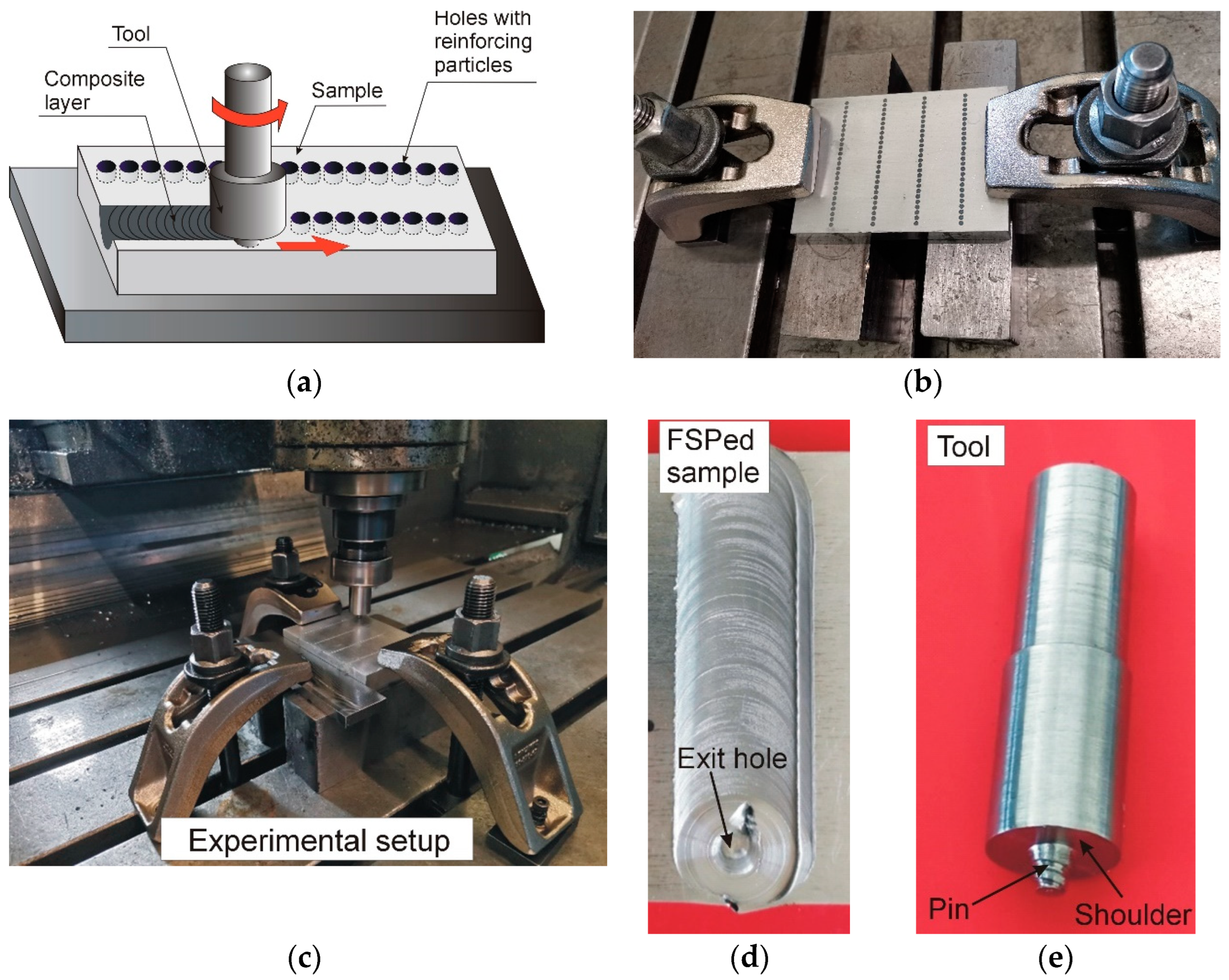
The composite surface layer was produced by means of the FSP method. An original solution was used to introduce the reinforcing phase into the metal matrix, namely the hole method with a shifted working zone of the tool [35]. In the hole method, the reinforcing material is placed in cylindrical chambers hollowed out in the sample surface. Such chambers act as reservoirs from which the reinforcing material is directed to the plasticized matrix using a tool. A diagram of the hole method is shown in Figure 5a, and Figure 5b–e present the subsequent stages of friction stir processing using the hole method, the tool utilized in the FSP method, and the macroscopic effect of processing with a characteristic “exit hole” at the end of the band.
The introduction of the reinforcing phase requires prior plasticization of the matrix. This is achieved thanks to the heat generated by the friction of the tool against the material being modified and as a result of intense plastic deformation. The heat generated during FSP causes a local increase in the temperature of the material up to approximately 80% of its melting temperature, which is sufficient to plasticize it. The plasticized material then behaves like a high-density fluid [48]. As a result of the combined effect of heat and strong plastic deformation of the material, significant microstructural changes occur in the material, the scope and nature of which result from the processing parameters, dimensions and geometry of the tool, properties of the processed material, and the cooling used.
FSP machining was performed with a 3-axis CNC milling machine (AVIA FNE 50, AVIA S.A., Warsaw, Poland). A cylindrical tool with a shoulder diameter of 18 mm, equipped with a 5 mm long cone-shaped pin and a threaded side surface was employed (Figure 5e). The rotational speed of the tool was 400 rpm and the traverse speed was 30 mm/min. The shoulder tilt angle was fixed at 2°. The tool was made of hot work tool steel X37CrMoV5-1 (H11). The chambers hollowed out in the sample had a diameter of 2 mm and a depth of 4.6 mm. The thickness of the wall separating the individual chambers was 0.25 mm. Two-stage FSP treatment was carried out.
In the first phase of processing, the tool travel axis was at distance ΔL = 2.5 mm from the axis of the chambers, while in the second phase of processing, the tool moved centrally along the line of the chambers. The value of ΔL, which is a measure of the displacement of the tool pin in relation to the chamber lines, was determined experimentally during tests preceding the actual processing. By moving the working zone of the tool, direct contact of the tool pin with the modifying material at the stage of its penetration into the material was limited, and the risk of powder escaping outside the modified zone was minimized to a greater extent than in the case of the standard hole method. It is worth noting that by limiting contact with the hard reinforcing phase, the wear of the pin is reduced, and thus the risk of contamination of the modified sample with wear products is reduced and the frequency of replacing the tool with a new one is reduced as well. Contact with the reinforcing phase occurs, of course, at a later stage of processing, but the abrasive effect of the reinforcing phase on the pin is already buffered by the matrix plasticized in the meantime. The second pass of the tool was performed to obtain a more even distribution of the reinforcing phase in the composite matrix. For comparison purposes, a composite reinforced with SiC particles, one of the most frequently used reinforcing materials in composites, was also made. The manufactured composites were subjected to comparative microstructural tests, and hardness and wear-resistance measurements.
4. Results and Discussion
4.1. Microscopic Examinations
The transformations occurring in the material during FSP treatment are initiated and stimulated by the combined effect of heat and plastic deformation to which the material is subjected. The effect of friction stir processing is the presence of characteristic zones in the modified material, differentiated both in terms of structure and microstructure, and their location in the surface layer of the material. They are the stirring zone (SZ), the thermomechanically affected zone (TMAZ), and the heat-affected zone (HAZ) adjacent to the base material BM. The material located in the stirring zone is subject to the strongest plastic deformation and the highest temperature during friction stir processing. A characteristic feature of the stirring zone is the presence of very fine equiaxed grains, which proves that the microstructure of the material was formed under conditions of dynamic recrystallization. This effect was also noted in the samples examined in this study (Figure 6a).
It should be noted, however, that the grain size was not the same throughout the stirring zone. This is because the thermal effect generated directly at the surface, i.e., under the tool shoulder, is different than that generated in the lower parts of the pin working zone. Therefore, when assessing the degree of refinement, the average grain size, or even more often, the grain size range is given. In the case of the analyzed samples, the grain size in the stirring zone ranged from 1 to 4 µm, regardless of the reinforcing phase used. The identical degree of grain refinement in these samples indicates that despite the use of different reinforcing materials, the course and kinetics of dynamic recrystallization were similar in all the composites. Dynamic recrystallization (DRX) is the main mechanism responsible for grain refinement in friction stir processed metals and metal alloys, and similar to static recrystallization (SRX), it may involve the formation and growth of recrystallization nuclei. However, unlike static recrystallization, in the case of DRX, the processes of the nucleation and growth of nuclei occur during plastic deformation of the material, and not after plastic deformation. The type and kinetics of dynamic recrystallization are influenced by many factors, which can be generally divided into factors resulting from the type of material used (e.g., initial grain size, stacking fault energy of the modified material, the presence of second phase particles and their size) and factors resulting from the employed processing parameters (e.g., temperature and strain rate, degree of material deformation, material cooling intensity, pin shape, number of tool passes). As part of this work, all the samples were processed using analogous parameters and cooling conditions; the only difference resulted from the use of different reinforcing materials. The particles of the reinforcing phase may constitute recrystallization nuclei during recrystallization and facilitate recrystallization or lead to slower recrystallization and inhibition of the grain growth of the material. The latter situation occurs when particles are located on the boundaries of newly formed grains, which leads to blockage of the movement of grain boundaries and recrystallization fronts, and thus to the limitation of grain growth. This is the so-called Zener effect. The key parameter determining the actual role of particles and their impact on the kinetics of recrystallization and grain boundary migration is primarily the particle size, which, as should be emphasized, may change during processing with the progressive deformation of the material or the number of repetitions of FSP treatment. The reinforcing phases used in this work were characterized by a predominant share of small-sized particles, the presence of which in the material favored the formation of a fine-grained microstructure. It is worth noting here that high grain refinement is one of the main goals of FSP treatment, and the obtained degree of grain refinement is the effect of heat acting on the material or the amount of plastic deformation of the material. As indicated by the research results of Xie et al. [49,50] regarding the production of composites via deformation-driven metallurgy, due to the strong plastic deformation of the material and dynamic recrystallization, not only can strong refinement of the matrix grains be achieved, but also uniform dispersion of the reinforcing phase in the composite. Multiple FSP passes also allow greater grain refinement and, at the same time, improve the uniformity of the distribution of the reinforcing phase. Each subsequent pass of the tool leads to the re-occurrence of dynamic recrystallization of the material and a more thorough mixing of the material, which results in an increase in the degree of grain refinement and higher homogeneity of the composite microstructure. An additional improvement in the uniformity of the distribution of the reinforcing phase can also be achieved by changing the direction of mixing the material with each subsequent pass of the tool [51]. The hole solution with the shifted working zone of the pin used in this work is a two-stage solution, thanks to which it is possible to obtain better microstructural effects than in the case of single-stage processing. Multiple processing is particularly recommended when producing particle-reinforced composites that tend to form clusters and agglomerates. It is also worth adding that the degree of grain refinement may also be influenced by additional cooling during processing. This is currently an important trend in FSP and a very promising direction of research [52].
Taking into account the main goal of the work, special attention was paid to the assessment of the composite microstructure in the context of the reinforcing phase introduced into the matrix. Examples of microstructures of the obtained composites are shown in Figure 7. The microscopic examinations revealed that as a result of FSP treatment, a composite layer with a thickness of approximately 4 mm to 5 mm was created. The thickness of the composite layer usually corresponds to the length of the pin of the tool employed in the processing, although the dimensions of this layer are also influenced by other processing parameters. The microscopic examinations also disclosed that the particles of the reinforcing phase were located primarily in the stirring zone. In the zone adjacent to the stirring zone, i.e., in the thermomechanically affected zone, there were also particles of the reinforcing phase, but their number was much smaller. A characteristic feature of the TMAZ zone was the presence of grains with an elongated shape reflecting the direction of flow of the plasticized material. It is worth explaining here that in the thermomechanically affected zone, the material also undergoes plastic deformation, but dynamic recrystallization does not occur or its scope is limited, which results in the formation of a microstructure that is at most partially recrystallized.
In none of the analyzed samples were particle clusters or agglomerates found in the stirring zone, which proves the correct selection of the FSP parameters. The uniformity of particle distribution in the matrix is an extremely important criterion for assessing the microstructure of the composite, determining its properties and behavior during operation. Nonetheless, when comparatively assessing the microstructures presented in Figure 7, it can be seen that the most uniform distribution of the reinforcing phase in the matrix was obtained in the case of SiC powder. This effect is caused primarily by the greater uniformity of this powder in terms of the shape and size of the particles constituting it, which causes individual particles in the plasticized matrix to behave in a very similar and, therefore, more predictable way. In the case of the powders consisting of particles that differ significantly in morphology and size, the particles with a smaller diameter and smaller specific surface area are more susceptible to movement in the plasticized matrix than larger particles with a less regular shape and a more extensive geometric surface structure.
Another important criterion for evaluating a composite is the particle–matrix interface. If the particles of the reinforcing phase are isolated from the matrix or the contact of the reinforcing phase with the matrix is limited, it is not possible to fully exploit the benefits resulting from the introduction of the reinforcing phase into the matrix, and what is more, such particles are easily chipped, e.g., during the operation of the composite in abrasive wear conditions. The conducted investigations revealed that despite their very diverse shapes and sizes, the particles bonded well with the matrix. It is worth mentioning here that no liquid phase is formed during FSP treatment, thus potential problems with wetting the surface of the reinforcing phase by the liquid metal matrix do not occur at all. In this way, one of the factors limiting the contact of the reinforcing phase with the matrix is eliminated. This is a significant advantage of the FSP method.
One of the effects of FSP treatment was a reduction in the number of precipitates of intermetallic phases, numerous in the starting material, combined with a more even redistribution of the remaining, not yet dissolved precipitates. Intermetallic phases have a significant impact on the properties of the aluminum alloy; hence, their reduction may result in deterioration of the mechanical properties of the material. This issue is analyzed later in this study.
4.2. Hardness Measurement
The key parameter verifying the correctness of the selection of the processing parameters and indicating the extent to which the friction modification and the reinforcing phase introduced into the matrix affect the material properties is hardness. This is a basic parameter in assessing the utility value of surface layers and the effectiveness of methods employed to modify these surfaces. Therefore, great importance was attached to the hardness measurement results. Hardness measurements were made on cross-sectional surfaces in the central part of the stirring zone. The tests were conducted using a Shimatzu hardness tester (Shimatzu Corp., Kyoto, Japan) with a load of 980.7 mN. All the produced samples were tested. The results of hardness measurement as a function of distance from the surface are shown in Figure 8.
The hardness increased in all the samples, regardless of the type of reinforcement used. Despite the dissolution of some of the intermetallic phases found during the microscopic examination, no sample had a hardness lower than that of the initial aluminum alloy. In the case of the composite reinforced with the A-1 powder, the growth in hardness was approximately 41%, while in the case of the A-2 powder, the composite achieved an average value of HV0.1 = 132, which was approximately 36% higher than the hardness of the starting material. In the case of the material reinforced with SiC particles, the rise in hardness was the highest and exceeded 43%. The change in the hardness of the material after FSP was primarily a consequence of introducing the hard particles of the reinforcing phase into the matrix and the strong refinement of the grains caused by the dynamic recrystallization of the material. According to the Hall–Petch relationship, as the degree of grain refinement grows, the hardness of metals and their alloys increases [53,54]. This is because, as a result of reducing the grain size, the number of grain boundaries rises, which constitute a barrier to dislocations and act as pinning points, inhibiting their further propagation. This mechanism is the basis of so-called edge amplification or Hall–Petch amplification. However, it is worth noting here that an equally important factor influencing the course of dynamic recrystallization and its kinetics is the presence of second-phase particles. The role these particles play depends on their size. Large particles can constitute recrystallization nuclei and facilitate recrystallization of the material, while small particles lead to slower recrystallization and the inhibition of grain growth, thus contributing to a greater degree of grain refinement in the material. The powders used in the study were characterized by a very large variation in particle size, but it should be noted that small particles predominated, their dimensions usually not exceeding a few micrometers. Such particles, located on the boundaries of newly formed grains, block the movement of grain boundaries and recrystallization fronts, and thus limit grain growth. Moreover, as a result of the mechanical interaction of the tool with the reinforcing phase, it cannot be ruled out that additional refinement of the particles of this phase may occur, resulting in an increment in the number of smaller particles. The effect of additional refinement of the reinforcing phase during FSP was, among others, noted by the authors of this work during the FSP of a cast composite based on an aluminum alloy reinforced with SiC particles [55]. Large differences in the particle size and shape among the powders used in the research conducted in this study make it difficult to draw clear conclusions about the occurrence of the refinement effect of the reinforcing phase.
A comparative assessment of the hardness measurement results reveals that in the case of the SiC and A-1 particles, a decrease in hardness occurred at a depth of approximately 5 mm from the surface, which is almost a millimeter greater than in the case of the A-2 powder. This fact can be explained primarily by the differences in the shape and morphology of the powders used. Powder A-2 was characterized by a more complex shape and geometric surface structure, which made it difficult to distribute the particles throughout the volume of the plasticized composite matrix. It is also worth noting that in the case of the composite reinforced with the A-1 particles, the hardness level was comparable to the hardness of the material reinforced with SiC particles. The hardness of the composite reinforced with the A-2 particles was approximately 7% lower than the hardness of the reference sample.
4.3. Wear Resistance Tests
Abrasive wear resistance, next to hardness measurement, is one of the basic parameters verifying the effectiveness of the conducted surface treatment. As part of this work, wear resistance tests were performed by means of a T01-M tester (ITEE, Radom, Poland) employing the pin-on-disc method. The tests were carried out under dry friction conditions at the temperature of 23 °C. All the samples after FSP friction modification, as well as the aluminum alloy in its initial state, were subjected to tribological tests. The research was of a comparative nature to illustrate both the differences in the wear resistance of the composites depending on the reinforcing phase used and also the changes in the tribological properties of the material caused by FSP treatment. During the tests, the linear wear of the tested sample was recorded. The test samples had the form of a cylinder with a diameter of 4 mm and a height of 15 mm and were cut from the central part of the band, perpendicular to its surface. The counter sample was made of bearing steel EN 100Cr6 [56] (E52100 according to AISI). The rotational speed of the counter sample was 150 rpm, and the test duration was 90 min. The load during the test was constant and amounted to 20 N. The selection of the tribological test parameters was based on previous experiments conducted with the AA7075 aluminum alloy and composites manufactured using the FSP method. The samples for the tribological tests were subjected to preparatory processing consisting of grinding a thin surface layer with a thickness of approximately 20 µm. Initial microscopic examinations showed that the geometric structure of individual samples differs, which could affect the accuracy of the tribological tests. During the microscopic examinations, it was found that the maximum depth of furrows and grooves formed on the surface of the samples as a result of FSP treatment does not exceed approximately 20 µm; therefore, it was decided to remove the surface layer of this thickness before the tribological tests. The tribological tester was utilized to remove the surface layer. The abrasion process was completed when the tester’s measurement system registered a linear loss of the assumed value, i.e., 20 µm. In this way, uniform starting conditions were achieved and potential measurement errors resulting from differences in the surface geometry of individual samples were eliminated.
The results of the tribological test are presented in the figures in the form of the “linear sample loss-test duration” characteristic (Figure 9). Taking into account the previous hardness measurement results, improvement in the wear resistance of the aluminum alloy was expected after the introduction of the reinforcing phase. This was also the obtained effect. All the analyzed samples were characterized by higher wear resistance than the starting material. The improvement in wear resistance was primarily a consequence of the presence of the hard reinforcing phase in the composite matrix, but also of strong grain refinement in the stirring zone. As follows from the Archard wear model [57], the rate of material wear is inversely proportional to the hardness of the material, and the hardness, in turn, depends on the microstructure, including the degree of grain refinement.
The analysis of the influence of the type of reinforcing phase on the wear resistance revealed that the sample reinforced with SiC particles had the lowest linear loss, while the sample reinforced with the A-1 particles also exhibited only slightly lower resistance, while the highest linear loss was recorded in the case of the sample reinforced with the A-2 particles. Nonetheless, it should be emphasized that the wear resistance of the sample reinforced with the A-2 particles was still much higher than that of the AA7075 aluminum alloy, which proves the advisability of using this material as a reinforcing phase in composites.
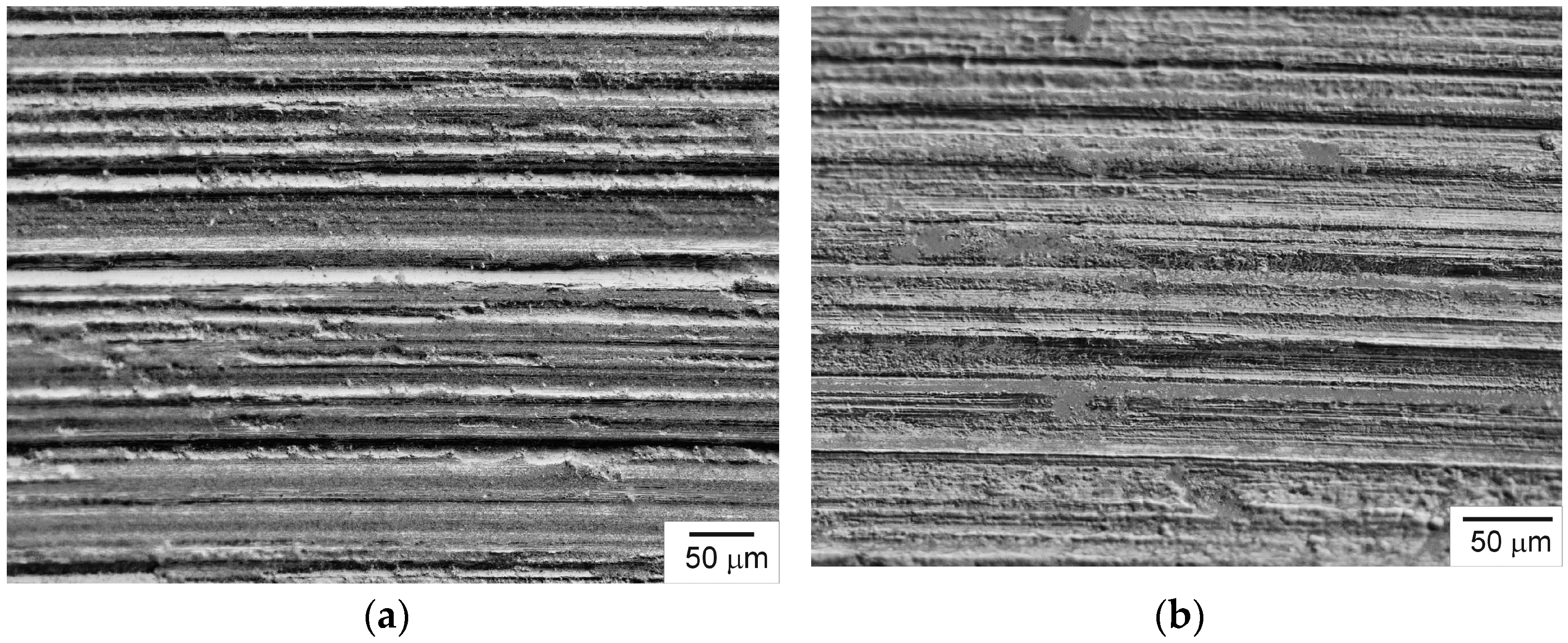
In order to identify the wear mechanism, microscopic examinations of the sample surfaces were carried out after the tribological tests. All the samples were found to have characteristic scratches and grooves resulting from micro-cutting and micro-plowing, the presence of which indicates the abrasive wear mechanism of the samples. Examples of worn composite surfaces are shown in Figure 10. The main cause of scratches and grooves was the presence of particles of the reinforcing phase in the contact area, and also irregularities on the surface of the steel counter-sample.
5. Conclusions
The basic criteria for assessing the suitability of reinforcing phases were the changes observed in the material microstructure and composite properties. Despite the differences in the shape, size, and morphology of the reinforcing phases used, a composite surface layer was obtained in all researched material variants, and the FSP treatment was accompanied by favorable changes in the matrix, expressed in strong grain refinement, a more uniform distribution of intermetallic phases, and the disappearance of the rolling microstructure.
The average grain size in the starting material was 290 µm, while in the stirring zone of the friction stir processed material, it ranged from 1 to 4 µm, regardless of the reinforcing phase used.
A side effect of FSP treatment was a reduction in the share of intermetallic phases owing to their partial dissolution in the solid solution. However, reducing the content of intermetallic phases did not lower the hardness or resistance of the material to abrasive wear. As the studies showed, the effects of dissolving the phases in the solid solution were effectively compensated for by the introduction of the reinforcing phase into the matrix, strong grain refinement, and more even redistribution of the remaining, not yet dissolved, precipitates.
Changes in the microstructure caused by FSP treatment and the introduction of a reinforcing phase resulted in a significant rise in hardness and abrasive wear resistance compared to the properties of the AA7075 aluminum alloy. The average hardness of the material reinforced with the A-1 phase was HV0.1 = 137, and the material reinforced with the A-2 phase was HV0.1 = 132, which corresponded to growth in the hardness of the material after FSP treatment and the introduction of the reinforcing phase by 41% and 36%, respectively.
The linear loss of the sample reinforced with the A-1 phase in the tribological test was 118.5 µm, and the sample containing the A-2 phase was 134 µm. This loss in the case of the initial aluminum alloy was 176.6 μm; therefore, it was higher by 49% and 32%, respectively, compared to the linear loss recorded for the composite samples reinforced with phases A-1 and A-2. The abrasive wear resistance, expressed by the size of the registered linear losses of the samples, was therefore 32.9% higher in the case of the composite reinforced with the A-1 phase than that of the abrasion resistance of the AA7075 aluminum alloy and by 24.1% in the case of the A-2 reinforcing phase.
The conducted research has shown that the reinforcing phases investigated in this work in the form of ash from the combustion of fossil fuels and biomass can constitute a valuable component in the production of metal matrix surface composites. Nonetheless, when deciding to use them, one should take into account the risk of the high variability of the chemical composition and morphology of these materials depending on the type of raw material used or the parameters of the technological process.
Author Contributions
Conceptualization, J.I.; methodology, J.I. and K.K.; material research, J.I., K.K. and M.S.; writing, J.I., K.K. and M.S.; review and editing, J.I., K.K. and M.S.; supervision, J.I. All authors have read and agreed to the published version of the manuscript.
Funding
This research received no external funding.
Institutional Review Board Statement
Not applicable.
Informed Consent Statement
Not applicable.
Data Availability Statement
The raw data supporting the conclusions of this article will be made available by the authors on request.
Conflicts of Interest
The authors declare no conflicts of interest.
References
- Chen, R.; Wang, H.; Li, J.; He, B.; Shao, W.; Zhang, S. Effect of laser remelting and heat treatment on microstructure and wear resistance of 2A97 Al-Li alloy. Surf. Interfaces 2022, 33, 102197. [Google Scholar] [CrossRef]
- Benedetti, A.; Cabeza, M.; Castro, G.; Feijoo, I.; Mosquera, R.; Merino, P. Surface modification of 7075-T6 aluminium alloy by laser melting. Surf. Interface Anal. 2012, 44, 977–981. [Google Scholar] [CrossRef]
- Luo, G.; Xiao, H.; Li, S.; Wang, C.; Zhu, Q.; Song, L. Quasi-continuous-wave laser surface melting of aluminium alloy: Precipitate morphology, solute segregation and corrosion resistance. Corros. Sci. 2019, 152, 109–119. [Google Scholar] [CrossRef]
- Mishra, R.S.; Mahoney, M.W. Friction stir processing: A new grain refinement technique to achieve high strain rate superplasticity in commercial alloys. Mater. Sci. Forum 2001, 357–359, 507–514. [Google Scholar] [CrossRef]
- Mishra, R.S.; Ma, Z.Y. Friction stir welding and processing. Mater. Sci. Eng. R Rep. 2005, 50, 1–78. [Google Scholar] [CrossRef]
- Thomas, W.M.; Nicholas, E.D.; Needham, J.C.; Murch, M.G.; Templesmith, P.; Dawes, C.J. International Patent Application. No. PCT/GB92/02203 and GB Patent Application No. 9125978.8, December 1991. [Google Scholar]
- Ahmed, M.M.Z.; El-Sayed Seleman, M.M.; Fydrych, D.; Çam, G. Friction Stir Welding of aluminum in the aerospace industry: The current progress and state-of-the-art review. Materials 2023, 16, 2971. [Google Scholar] [CrossRef] [PubMed]
- Kosturek, R.; Torzewski, J.; Joska, Z.; Wachowski, M.; Śnieżek, L. The influence of tool rotation speed on the low-cycle fatigue behavior of AA2519-T62 friction stir welded butt joints. Eng. Fail. Anal. 2022, 142, 106756. [Google Scholar] [CrossRef]
- Khalaf, H.I.; Al-Sabur, R.; Demiral, M.; Tomków, J.; Łabanowski, J.; Abdullah, M.E.; Derazkola, H.A. The effects of pin profile on HDPE thermomechanical phenomena during FSW. Polymers 2022, 14, 4632. [Google Scholar] [CrossRef] [PubMed]
- Janeczek, A.; Tomków, J.; Fydrych, D. The influence of tool shape and process parameters on the mechanical properties of aw-3004 aluminium alloy friction stir welded joints. Materials 2021, 14, 3244. [Google Scholar] [CrossRef] [PubMed]
- Kosturek, R.; Torzewski, J.; Wachowski, M.; Śnieżek, L. Effect of welding parameters on mechanical properties and microstructure of friction stir welded AA7075-T651 aluminum alloy butt joints. Materials 2022, 15, 5950. [Google Scholar] [CrossRef] [PubMed]
- Nasiri, Z.; Sarkari Khorrami, M.; Mirzadeh, H.; Emamy, M. Enhanced mechanical properties of as-cast Mg-Al-Ca magnesium alloys by friction stir processing. Mater. Lett. 2021, 296, 129880. [Google Scholar] [CrossRef]
- Patel, V.; Li, W.Y.; Andersson, J.; Li, N. Enhancing grain refinement and corrosion behavior in AZ31B magnesium alloy via stationary shoulder friction stir processing. J. Mater. Res. Technol. 2022, 17, 3150–3156. [Google Scholar] [CrossRef]
- Iwaszko, J.; Kudła, K. Microstructure, hardness, and wear resistance of AZ91 magnesium alloy produced by friction stir processing with air-cooling. Int. J. Adv. Manuf. Technol. 2021, 116, 1309–1323. [Google Scholar] [CrossRef]
- Asl, H.G.; Celik-Uzuner, S.; Uzuner, U.; Sert, Y.; Küçükömeroğlu, T. The effect of friction stir process on the mechanical, tribological, and biocompatibility properties of AZ31B magnesium alloy as a biomaterial: A pilot study. Proc. Inst. Mech. Eng. H J. Eng. Med. 2022, 236, 1720–1731. [Google Scholar]
- Iwaszko, J.; Kudła, K. Evolution of Microstructure and properties of air-cooled friction-stir-processed 7075 aluminum alloy. Materials 2022, 15, 2633. [Google Scholar] [CrossRef]
- Meng, X.; Huang, Y.; Cao, J.; Shen, J.; dos Santos, J.F. Recent progress on control strategies for inherent issues in friction stir welding. Prog. Mater. Sci. 2021, 115, 100706. [Google Scholar] [CrossRef]
- Choudhary, A.K.; Jain, R. Fundamentals of friction stir welding, its application, and advancements. In Welding Technology; Springer Nature: Cham, Switzerland, 2021; pp. 41–90. [Google Scholar]
- Mishra, R.S.; Ma, Z.Y.; Charit, I. Friction stir processing: A novel technique for fabrication of surface composite. Mater. Sci. Eng. A 2003, 341, 307–310. [Google Scholar] [CrossRef]
- Mirzadeh, H. Surface metal-matrix composites based on AZ91 magnesium alloy via friction stir processing: A review. Int. J. Miner. Metall. Mater. 2023, 30, 1278–1296. [Google Scholar] [CrossRef]
- Sudhakar, M.; Srinivasa, C.H.; Rao, K.; Saheb, M. Production of surface composites by friction stir processing. A review. Mater. Today Proc. 2018, 5, 929–935. [Google Scholar] [CrossRef]
- Wu, B.; Ibrahim, M.Z.; Raja, S.; Yusof, F.; Abdul Razak, B.B.; Bin Muhamad, M.R.; Huang, R.; Zhang, Y.; Badruddin, I.A.; Hussien, M.; et al. The influence of reinforcement particles friction stir processing on microstructure, mechanical properties, tribological and corrosion behaviors: A review. J. Mater. Res. Technol. 2022, 20, 1940–1975. [Google Scholar] [CrossRef]
- Teo, G.S.; Liew, K.W.; Kok, C.K. A study on friction stir processing parameters of recycled AA 6063/TiO2 surface composites for better tribological performance. Metals 2022, 12, 973. [Google Scholar] [CrossRef]
- Sharma, V.; Tripathi, P. Approaches to measure volume fraction of surface composites fabricated by friction stir processing: A review. Measurement 2022, 193, 110941. [Google Scholar] [CrossRef]
- Heidarzadeh, A.; Taghizadeh, B.; Mohammadzadeh, A. In-situ formation of Zn oxide particles in CuZn matrix during friction stir processing. J. Adhes. Sci. Technol. 2021, 35, 1006–1013. [Google Scholar] [CrossRef]
- Bagheri, B.; Abbasi, M. Development of AZ91/SiC surface composite by FSP: Effect of vibration and process parameters on microstructure and mechanical characteristics. Adv. Manuf. 2020, 8, 82–96. [Google Scholar] [CrossRef]
- Velmurugan, T.; Subramanian, R.; Suganya Priyadharshini, G.; Raghu, R. Experimental investigation of microstructure, mechanical and wear characteristics of Cu-Ni/ZrC composites synthesized through friction stir processing. Arch. Metall. Mater. 2020, 65, 565–574. [Google Scholar] [CrossRef]
- Sanusi, K.O.; Akinlabi, E.T. Experimental investigation of magnesium alloy processed by friction stir process using stainless steel powder as matrix composite. Mater. Today Proc. 2018, 5, 18468–18474. [Google Scholar] [CrossRef]
- Heidarzadeha, A.; Pouraliakbarb, H.; Mahdavic, S.; Jandaghi, M.R. Ceramic nanoparticles addition in pure copper plate: FSP approach, microstructure evolution and texture study using EBSD. Ceram. Int. 2018, 44, 3128–3133. [Google Scholar] [CrossRef]
- Pol, N.; Verma, G.; Pandey, R.P.; Shanmugasundaram, T. Fabrication of AA7005/TiB2-B4C surface composite by friction stir processing: Evaluation of ballistic behavior. Def. Technol. 2019, 15, 363–368. [Google Scholar] [CrossRef]
- Wang, T.; Gwalani, B.; Shukla, S.; Frank, M.; Mishra, R.S. Development of in situ composites via reactive friction stir processing of Ti-B4C system. Compos. B Eng. 2019, 172, 54–60. [Google Scholar] [CrossRef]
- Liang, J.; Li, H.; Qi, L.; Tian, W.; Li, X.; Chao, X.; Wei, J. Fabrication and mechanical properties of CNTs/Mg composites prepared by combining friction stir processing and ultrasonic assisted extrusion. J. Alloys Compd. 2017, 728, 282–288. [Google Scholar] [CrossRef]
- Huang, Y.; Wang, T.; Guo, W.; Wan, L.; Lv, S. Microstructure and surface mechanical property of AZ31 Mg/SiCp surface composite fabricated by Direct Friction Stir Processing. Mater. Des. 2014, 59, 274–278. [Google Scholar] [CrossRef]
- Almazrouee, A.I.; Al-Fadhalah, K.J.; Alhajeri, S.N. A new approach to direct friction stir processing for fabricating surface composites. Crystals 2021, 11, 638. [Google Scholar] [CrossRef]
- Iwaszko, J.; Kudła, K.; Fila, K. Technological aspects of friction stir processing of AlZn5.5MgCu aluminum alloy. Bull. Pol. Acad. Sci. Tech. Sci. 2018, 66, 713–719. [Google Scholar]
- Ayvaz, S.I.; Arslan, D.; Ayvaz, M. Investigation of mechanical and tribological behavior of SiC and B4C reinforced Al-Zn-Mg-Si-Cu alloy matrix surface composites fabricated via friction stir processing. Mater. Today Commun. 2022, 31, 103419. [Google Scholar] [CrossRef]
- Bharti, S.; Ghetiya, N.D.; Patel, K.M.; Dutta, V. Investigating the influence of singlepass and double-pass friction stir processing on mechanical and wear behaviour of AA5083/Al2O3 surface. IOP Conf. Ser. Mater. Sci. Eng. 2021, 1136, 012071. [Google Scholar] [CrossRef]
- Abbass, M.K.; Baheer, N.A. Effect of SiC particles on microstructure and wear behavior of AA6061-T6 aluminum alloy surface composite fabricated by friction stir processing. IOP Conf. Ser. Mater. Sci. Eng. 2020, 671, 012159. [Google Scholar] [CrossRef]
- Dinaharan, I.; Akinlabi, E.T. Low cost metal matrix composites based on aluminum, magnesium and copper reinforced with fly ash prepared using friction stir processing. Compos. Commun. 2018, 9, 22–26. [Google Scholar] [CrossRef]
- Patil, N.A.; Zhongyan, N.; Pedapati, S.R.; Mamat, O.B. Investigation on effect of fly ash volume percentage on microstructure and microhardness of AA7075-fly ash surface composites via FSP. In Advances in Manufacturing Engineering: Selected Articles from ICMMPE; Springer: Singapore, 2020; pp. 399–410. [Google Scholar]
- Kumar, H.; Prasad, R.; Kumar, P.; Tewari, S.P.; Singh, J.K. Mechanical and tribological characterization of industrial wastes reinforced aluminum alloy composites fabricated via friction stir processing. J. Alloys Compd. 2020, 831, 154832. [Google Scholar] [CrossRef]
- Dinaharan, I.; Kalaiselvan, K.; Murugan, N. Influence of rice husk ash particles on microstructure and tensile behavior of AA6061 aluminum matrix composites produced using friction stir processing. Compos. Commun. 2017, 3, 42–46. [Google Scholar] [CrossRef]
- Kolli, M.; Dasari, S.N.; Potluri, N.S.; Ramprasad, A.V.S. Influence of rock dust reinforcement on mechanical properties of Al composite using friction stir processing. Aust. J. Mech. Eng. 2023, 21, 329–338. [Google Scholar] [CrossRef]
- Srivastava, A.K.; Dwivedi, S.; Nag, A.; Kumar, D.; Dixit, A.R.; Hloch, S. Microstructural, mechanical and tribological performance of a magnesium alloy AZ31B/Si3N4/eggshell surface composite produced by solid-state multi-pass friction stir processing. Mater. Chem. Phys. 2023, 301, 127694. [Google Scholar] [CrossRef]
- Patil, N.A.; Pedapati, S.R.; Mamat, O.B.; Lubis, A.M.H.S. Effect of SiC/Fly ash reinforcement on surface properties of aluminum 7075 hybrid composites. Coatings 2020, 10, 541. [Google Scholar] [CrossRef]
- Prakasam, S.; Kannakumar, K.; Mohanraj, D.; Karthi, M.; Sakthi, S.; Nanthakumar, S. Investigation on the metallurgical and welding characteristics of AA7075/Fly ash composites. Mater. Today Proc. 2024; in press. [Google Scholar] [CrossRef]
- Tyagi, L.; Butola, R.; Jha, A.K. Mechanical and tribological properties of AA7075-T6 metal matrix composite reinforced with ceramic particles and aloevera ash via friction stir processing. Mater. Res. Express 2020, 7, 066526. [Google Scholar] [CrossRef]
- Gałczyński, T.; Luty, G. Technologie łączenia struktur lotniczych; część 2; Zgrzewanie tarciowe liniowe z przemieszaniem (FSW-Friction Stir Welding). Proj. Konstr. Inż. 2018, 11, 134. [Google Scholar]
- Xie, Y.; Meng, X.; Li, Y.; Mao, D.; Wan, L.; Huang, Y. Insight into ultra-refined grains of aluminum matrix composites via deformation-driven metallurgy. Compos. Commun. 2021, 26, 100776. [Google Scholar] [CrossRef]
- Xie, Y.; Meng, X.; Chang, Y.; Mao, D.; Yang, Y.; Xu, Y.; Wan, L.; Huang, Y. Ameliorating strength-ductility efficiency of graphene nanoplatelet-reinforced aluminum composites via deformation-driven metallurgy. Compos. Sci. Technol. 2022, 219, 109225. [Google Scholar] [CrossRef]
- Adiga, K.; Herbert, M.A.; Rao, S.S.; Shettigar, A. Applications of reinforcement particles in the fabrication of aluminium metal matrix composites by friction stir processing—A review. Manuf. Rev. 2022, 9, 26. [Google Scholar] [CrossRef]
- Iwaszko, J. New Trends in Friction Stir Processing: Rapid Cooling—A Review. Trans. Indian Inst. Met. 2022, 75, 1681–1693. [Google Scholar] [CrossRef]
- Taha, A.S.; Hammad, F.H. Application of the Hall-Petch relation to microhardness measurements on Al, Cu, Al-MD 105, and Al-Cu alloys. Phys. Status Solidi A 1990, 119, 455–462. [Google Scholar] [CrossRef]
- Thangaraju, S.; Heilmaier, M.; Murty, B.S.; Vadlamani, S.S. On the estimation of true Hall-Petch constants and their role on the superposition law exponent in Al alloys. Adv. Eng. Mater. 2012, 14, 892–897. [Google Scholar] [CrossRef]
- Iwaszko, J.; Kudła, K. Effect of friction stir processing (FSP) on microstructure and hardness of AlMg10/SiC composite. Bull. Pol. Acad. Sci. Tech. Sci. 2019, 67, 185–192. [Google Scholar] [CrossRef]
- International Standard ISO 683-17; Heat-Treated Steels, Alloy Steels and Free-Cutting Steels—Part 17: Ball and Roller Bearing Steels. ISO: Geneva, Switzerland, 2014.
- Archard, J.F. Contact and rubbing of flat surface. J. Appl. Phys. 1953, 24, 981–988. [Google Scholar] [CrossRef]
Figure 1.
Microstructure of AA7075 alloy. Etched, light microscopy.

Figure 2.
Morphology of A-1 powder (a,b), morphology of A-2 powder (c,d), morphology of SiC powder (e,f). SEM.
Figure 2.
Morphology of A-1 powder (a,b), morphology of A-2 powder (c,d), morphology of SiC powder (e,f). SEM.

Figure 3.
Microstructure of A-1 powder with marked places subjected to EDS analysis (a), example EDS spectrum (microarea No. 5) (b).
Figure 3.
Microstructure of A-1 powder with marked places subjected to EDS analysis (a), example EDS spectrum (microarea No. 5) (b).
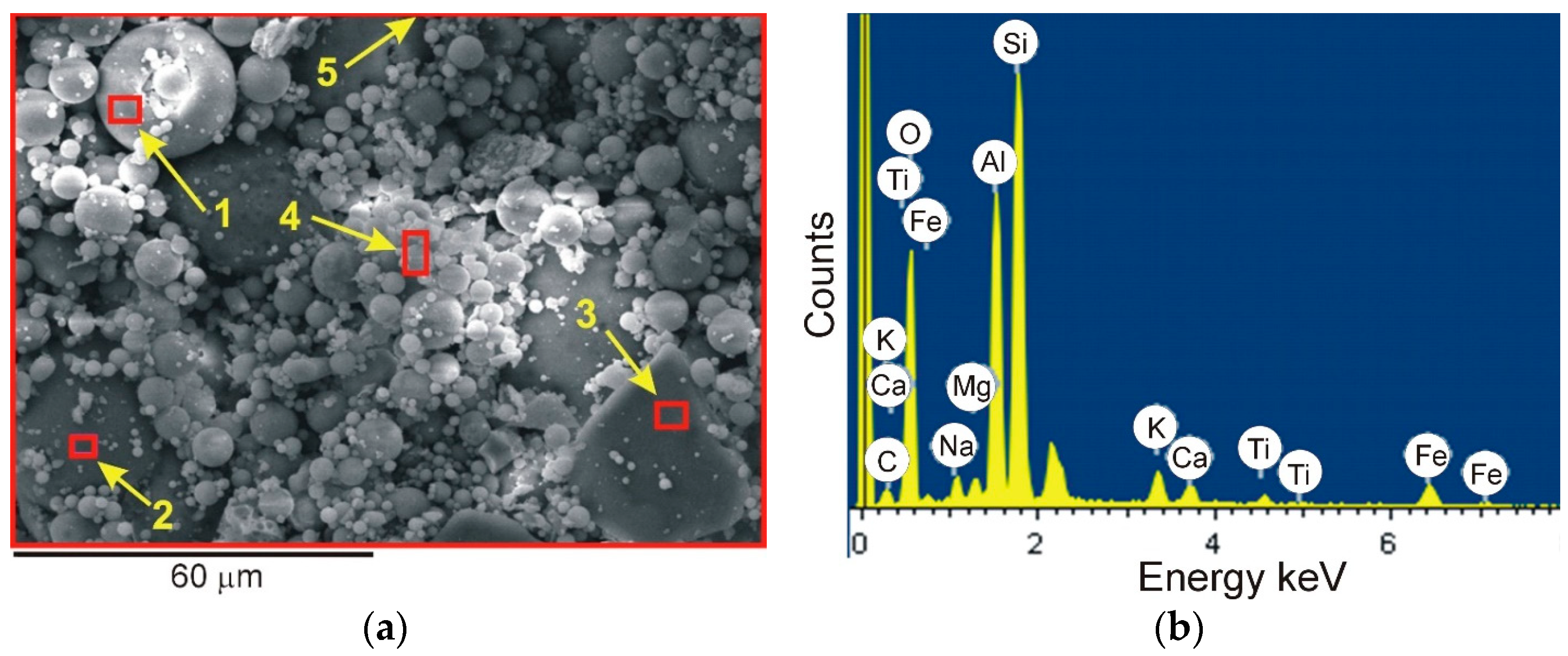
Figure 4.
Microstructure of A-2 powder with marked places subjected to EDS analysis (a), example EDS spectrum (microarea No. 4) (b).
Figure 4.
Microstructure of A-2 powder with marked places subjected to EDS analysis (a), example EDS spectrum (microarea No. 4) (b).
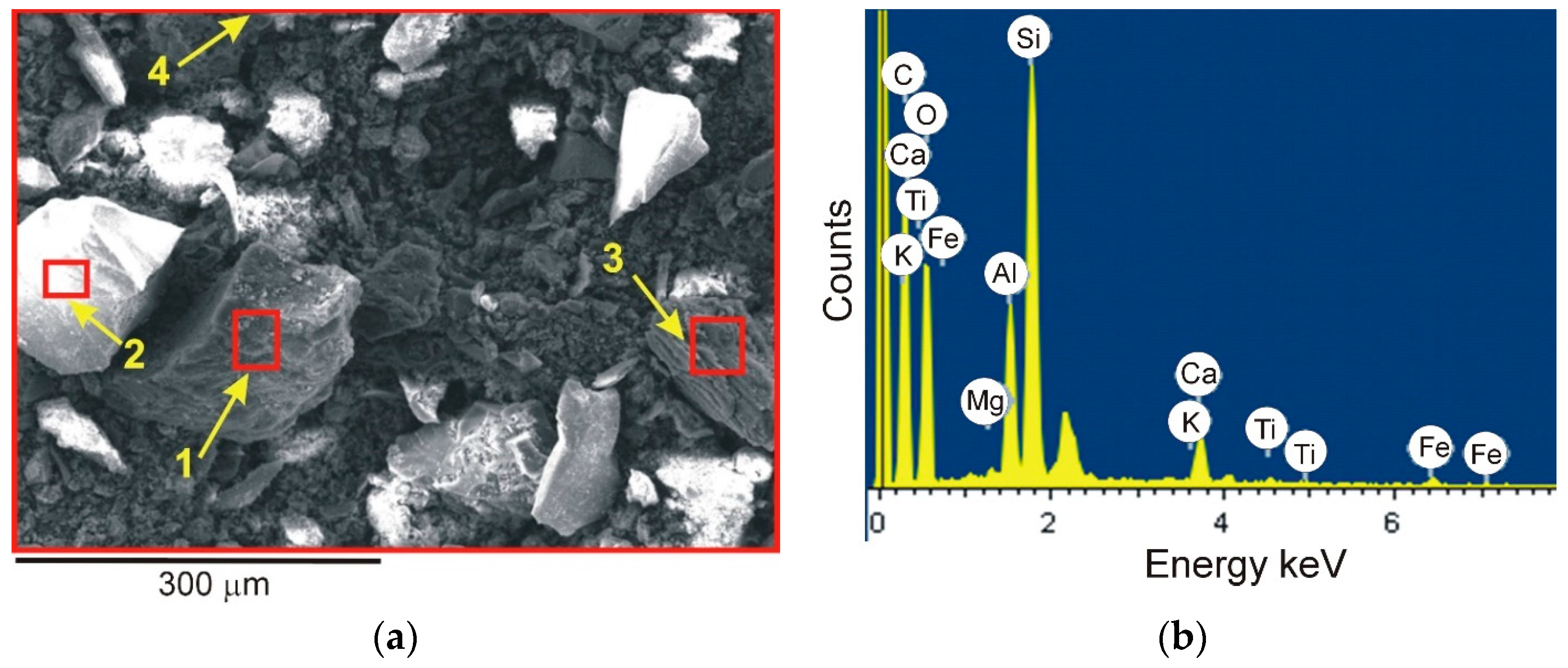
Figure 5.
Scheme of FSP hole method (a), sample after filling chambers with reinforcing phase (b), execution of FSP treatment (c), macroscopic effect of FSP treatment (d), tool (e).
Figure 5.
Scheme of FSP hole method (a), sample after filling chambers with reinforcing phase (b), execution of FSP treatment (c), macroscopic effect of FSP treatment (d), tool (e).

Figure 6.
Microstructure of stirring zone (a) and thermomechanically affected zone (b). Etched, light microscopy.
Figure 6.
Microstructure of stirring zone (a) and thermomechanically affected zone (b). Etched, light microscopy.
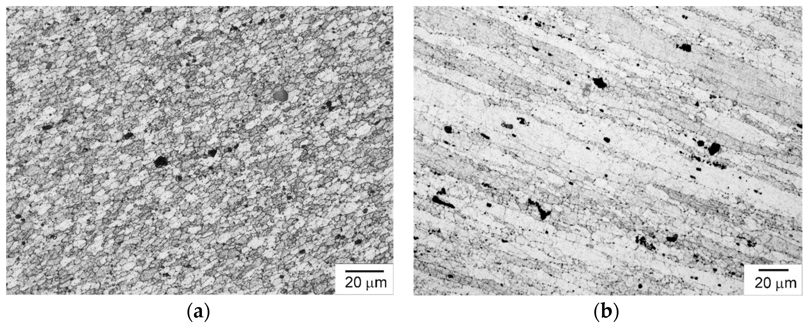
Figure 7.
Microstructure of composite reinforced with A-1 particles (a,b), A-2 particles (c,d), and SiC particles (e,f). Stirring zone (a,c,e), boundary of stirring zone, and thermomechanically affected zone (b,d,f). Etched, light microscopy.
Figure 7.
Microstructure of composite reinforced with A-1 particles (a,b), A-2 particles (c,d), and SiC particles (e,f). Stirring zone (a,c,e), boundary of stirring zone, and thermomechanically affected zone (b,d,f). Etched, light microscopy.
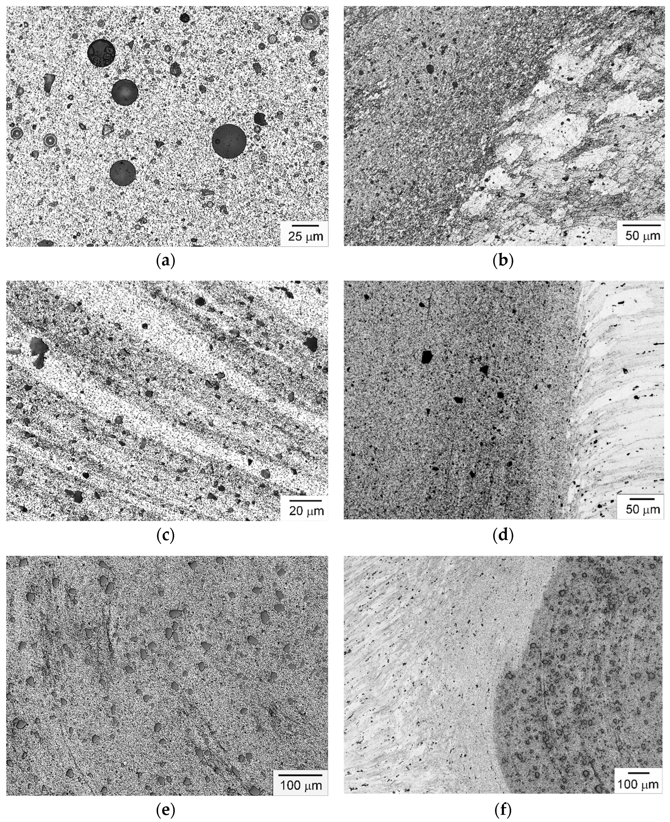
Figure 8.
Hardness measurement results.
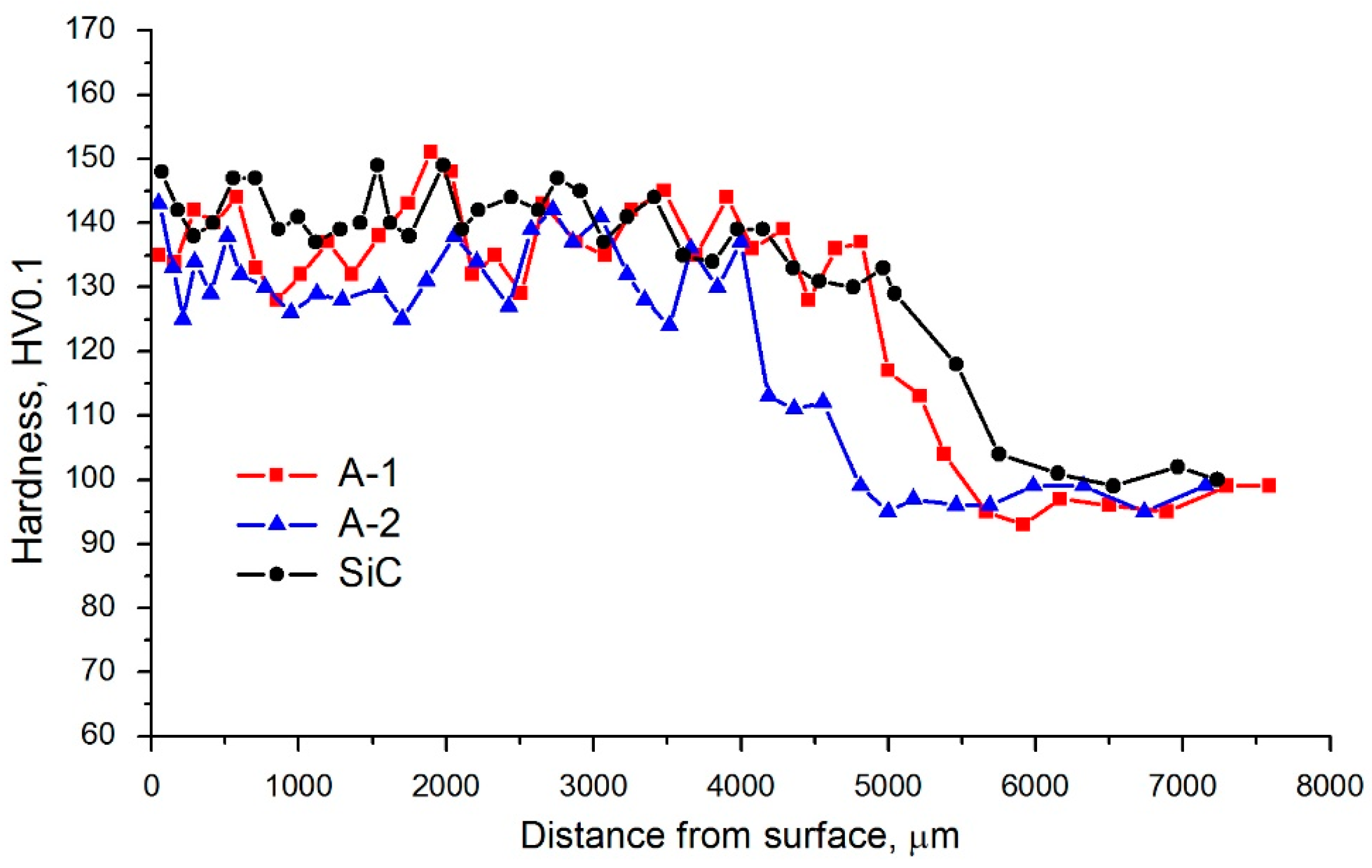
Figure 9.
Results of tribological tests.

Figure 10.
Worn surface of composite with A-1 reinforcing phase (a), and A-2 reinforcing phase A-2 (b). Light microscopy.
Figure 10.
Worn surface of composite with A-1 reinforcing phase (a), and A-2 reinforcing phase A-2 (b). Light microscopy.


Table 1.
Chemical composition of AA7075 aluminum alloy.
| Alloy | Element Content, wt% | ||||||||
|---|---|---|---|---|---|---|---|---|---|
| 7075 | Zn | Fe | Cu | Mn | Mg | Cr | Si | Ti | Al |
| 5.5 | 0.3 | 1.6 | 0.15 | 2.4 | 0.2 | 0.2 | 0.1 | 89.55 | |
Table 2.
Chemical composition of ashes.
| Ash | Element Content, wt% | ||||||||||
|---|---|---|---|---|---|---|---|---|---|---|---|
| SiO2 | Al2O3 | P2O5 | CaO | Fe2O3 | K2O | Na2O | MgO | TiO2 | SO3 | Other | |
| A-1 | 50.76 | 29.50 | 0.30 | 2.72 | 7.62 | 3.12 | 1.73 | 1.52 | 1.30 | 0.83 | 0.67 |
| A-2 | 60.47 | 17.89 | 2.22 | 6.74 | 3.65 | 0.88 | 0.88 | 1 | 0.75 | - | - |
Table 3.
Results of EDS analysis of A-1 powder.
| No. | Element Content, wt% | |||||||||
|---|---|---|---|---|---|---|---|---|---|---|
| C | O | Si | Al | Ca | Mg | Ti | Fe | Na | K | |
| 1 | - | 44.92 | 22.88 | 24.21 | - | - | 2.75 | 1.41 | 1.26 | 2.57 |
| 2 | - | 38.75 | 26.11 | 21.55 | - | 1.15 | 1.97 | 2.89 | 2.77 | 4.82 |
| 3 | - | 48.18 | 48.23 | 1.73 | - | - | - | - | 0.66 | 1.20 |
| 4 | - | 44.64 | 24.26 | 15.43 | 0.73 | 1.64 | 0.79 | 7.12 | 2.30 | 3.09 |
| 5 | 8.31 | 40.98 | 22.57 | 15.05 | 1.48 | 1.02 | 1.02 | 5.28 | 1.75 | 2.55 |
Table 4.
Results of EDS analysis of A-2 powder.
| No. | Element Content, wt% | |||||||||
|---|---|---|---|---|---|---|---|---|---|---|
| C | O | Si | Al | Ca | Mg | Ti | Fe | Na | K | |
| 1 | 67.40 | 23.89 | 2.47 | 2.78 | 1.83 | 0.29 | 0.53 | 0.81 | - | - |
| 2 | 13.27 | 44.16 | 42.25 | - | 0.31 | - | - | - | - | - |
| 3 | 81.61 | 13.33 | 2.30 | 1.45 | 0.71 | - | - | 0.33 | 0.28 | - |
| 4 | 45.41 | 34.84 | 10.81 | 4.63 | 2.43 | 0.21 | 0.37 | 1.15 | - | 0.16 |
Disclaimer/Publisher’s Note: The statements, opinions and data contained in all publications are solely those of the individual author(s) and contributor(s) and not of MDPI and/or the editor(s). MDPI and/or the editor(s) disclaim responsibility for any injury to people or property resulting from any ideas, methods, instructions or products referred to in the content. |
© 2024 by the authors. Licensee MDPI, Basel, Switzerland. This article is an open access article distributed under the terms and conditions of the Creative Commons Attribution (CC BY) license (https://creativecommons.org/licenses/by/4.0/).
Share and Cite
MDPI and ACS Style
Iwaszko, J.; Kudła, K.; Sajdak, M. The Use of Ashes in Surface Metal Matrix Composites Produced by Friction Stir Processing. Appl. Sci. 2024, 14, 3544. https://doi.org/10.3390/app14093544
AMA Style
Iwaszko J, Kudła K, Sajdak M. The Use of Ashes in Surface Metal Matrix Composites Produced by Friction Stir Processing. Applied Sciences. 2024; 14(9):3544. https://doi.org/10.3390/app14093544
Chicago/Turabian StyleIwaszko, Józef, Krzysztof Kudła, and Marcin Sajdak. 2024. "The Use of Ashes in Surface Metal Matrix Composites Produced by Friction Stir Processing" Applied Sciences 14, no. 9: 3544. https://doi.org/10.3390/app14093544
Note that from the first issue of 2016, this journal uses article numbers instead of page numbers. See further details here.