
Research and Design of the RF Cavity for an 11 MeV Superconducting Cyclotron

1
School of Physical Science and Technology, ShanghaiTech University, Shanghai 201210, China
2
Shanghai Institute of Applied Physics, Chinese Academy of Sciences, Shanghai 201800, China
*
Author to whom correspondence should be addressed.
Appl. Sci. 2024, 14(9), 3549; https://doi.org/10.3390/app14093549
Submission received: 29 March 2024
/
Revised: 19 April 2024
/
Accepted: 19 April 2024
/
Published: 23 April 2024
(This article belongs to the Special Issue Advances in Particle Acceleration: Novel Techniques, Instruments and Applications)
Abstract
:Featured Application
The focus of this paper is on the design of the RF (Radio Frequency) resonant cavities required for small modular superconducting cyclotrons. The design of these RF cavities aims to match the smaller extraction radius of superconducting cyclotrons and make easier of installation and maintenance. To this purpose, one has to adopt a design that allows for easy assembly and disassembly with the magnet system that has been adopted. Through the study of the circuitry of such RF cavities, along with calculations of electromagnetic fields and methods of frequency tuning, we provide a set of solutions that can serve as a reference for the design of smaller superconducting accelerators in the future. This not only helps in advancing the technology of superconducting cyclotrons but also can provide a method reference for related technical fields.
Abstract
In contrast to the room temperature cyclotron, the superconducting cyclotron’s high operational magnetic field and small extraction radius lead to a magnet design with a reduced radius. This limits the space available for the RF cavity in the 11 MeV superconducting cyclotron, necessitating a more compact RF cavity design. By using the transmission line theory, the complex structure of the quarter-wavelength coaxial cavity can be represented as a microwave circuit. Through relevant theoretical analytical formulas, equivalent circuit parameters can be derived. The resonant frequency of the RF cavity is then determined using the equivalent circuit method. The optimization of the RF cavity structure was achieved by creating a numerical model and conducting finite element numerical calculations on the high-frequency resonant system. The comparative results between the equivalent circuit and numerical calculations indicate that the frequency error remains within 0.1%, validating the compact RF cavity design. A multiple linear regression analysis facilitates the prediction of resonance frequency across various parameter variables. By analyzing the fitting formula, RF cavity machining error requirements are established, ensuring a prediction error within 1%, thus meeting engineering design criteria.
1. Introduction
Cyclotrons are pivotal tools for the production of medical radioisotopes due to their lower construction and operational costs compared to reactors [1,2,3]. With the growing prominence of positron emission tomography (PET) in biomedical imaging, the demand for positron-emitting isotopes has surged. Notably, 11C and 18F stand out as the most effective PET isotopes, characterized by their short half-lives of 20 and 108 min, respectively. Currently, the predominant method of producing 11C and 18F involves the use of low-energy cyclotrons (with energies below 15 MeV). A prevailing trend in the development of these cyclotrons is the emphasis on creating more compact, lightweight, and cost-efficient models [4,5,6]. Furthermore, there is a growing preference for cyclotrons that can operate in smaller settings and produce isotopes in proximity to patients. This approach aims to mitigate transportation challenges, minimize isotope activity loss, substantially reduce production costs, decrease the demand for associated infrastructure, and curtail expenses related to subsequent auxiliary equipment [7].
In the overall design of the cyclotron, a modularized assembly approach is adopted, allowing for the independent design of its key systems, including the particle source system, magnet system, and RF system [8,9]. During the preliminary design phase, it is essential to determine the specific parameters for each system and finalize the design of each independent module. Assembly is then carried out upon the completion of the research and design for each system. This modular design strategy not only curtails the research costs but also offers flexibility during maintenance, enabling the replacement of only the malfunctioning system. Such an approach enhances the development efficiency of the cyclotron, simplifies its debugging process, and reduces both operational and maintenance expenses.
For low-energy superconducting cyclotrons, the heightened magnetic field necessitates a reduced magnet radius for particle acceleration, leading to a diminished radial dimension for the RF cavity situated between the upper and lower magnets. Employing a conventional quarter-wavelength coaxial cavity would result in a length that significantly surpasses the radius of both the magnet and the vacuum chamber. This underscores the need for research into a more compact RF cavity design. To address the impedance matching challenge, an SIR (Stepped Impedance Resonator) structure is introduced. This resonator comprises a combination of two or more transmission lines, each with distinct characteristic impedances. The design permits an adjustment of the impedance ratio based on the radial size requirement, facilitating the resonator’s miniaturization. Furthermore, the quarter-wavelength coaxial SIR structure employed in this design is straightforward and amenable to fabrication [10].
The RF cavity is a pivotal component of the cyclotron primarily responsible for harnessing the accelerating electric field produced by high-frequency power coupling to propel charged particles. The RF cavity’s performance is intricately tied to its structural dimensions. Precise modeling and simulations are imperative to ascertain the design dimensions that align with the desired frequency. Cyclotron RF cavities, given their intricate structures, are typically analyzed and designed through both numerical and equivalent circuit calculations. For numerical evaluations, the common numerical method of high-frequency electromagnetic field calculation is the Finite Element Method (FEM), so the Finite Element Method is predominantly employed in the article [11]. For complex cavities, a unified computer modeling and calculation method can be used, which greatly simplifies the process and difficulty of resonant cavity analysis. At the same time, it can also be compared and verified with the equivalent circuit method. The equivalent circuit calculation leans on transmission line theory, which translates a complex coaxial cavity into multiple transmission lines, effectively rendering the resonant cavity as a standard microwave circuit model. This model streamlines the assessment of how each segment’s structural parameters influence the cavity’s characteristic parameters and offers a more direct route to design parameters. During this analytical process, pertinent circuit parameters are extracted, with the RF cavity’s resonant frequency ascertained using the equivalent circuit [12,13]. Both methodologies are concurrently employed in the design phase, with their results juxtaposed to bolster the precision and credibility of the resonant cavity analytical calculations.
2. Miniaturization of RF Cavity for an 11 MeV Superconducting Cyclotron
2.1. Structure of the Cyclotron’s RF Cavity Using the Stepped Impedance Resonator (SIR) Approach
Figure 1 illustrates the design of a quarter-wavelength coaxial cavity of a classical cyclotron. The short-circuit (S.C.) end is located at the Stem’s end, while the open-circuit (O.C.) end is at the Dee’s head, where the Dee is the accelerating electrode, and the Stem is the component that supports and fixes the Dee, and senses and balances the electric capacity of the Dee during resonance. This entire cavity can be conceptualized as an SIR structure, composed of two transmission line sections with distinct characteristic impedances. The characteristic impedances at the short-circuit and open-circuit ends of the transmission line are Z1 and Z2, respectively. Their electrical lengths are represented by θ1 and θ2, where θ = βl. In this equation, β stands for the propagation constant, and l signifies the length of the transmission line. For simplicity in analysis, the characteristic impedances Z1 and Z2 of the structure are assumed to be uniformly distributed [10,14,15].
Figure 1 can be regarded as the basic structure of the SIR, which includes an open-circuit end, a short-circuit end, and a step-junction surface. Here, O.C. denotes the open-circuit end, S.C. represents the short-circuit end, Zleft is the input impedance on the left side of the reference surface, and Zright is the input impedance on the right side of the reference surface. According to the input impedance formula [16]:
where Z0 is the characteristic impedance of the transmission line and ZL is the characteristic impedance of the end load. The left and right input impedances can be calculated by selecting the step junction surface as the input reference surface. When the step junction discontinuity and the edge capacitance effect at the open-circuit end are neglected, the total susceptance at the reference surface is zero, and the impedance ratio RZ0 is calculated as:
The resonance conditions of the structure depend on θ1, θ2, and the impedance ratio RZ0. Before the introduction of the SIR structure, the resonance condition of a typical quarter-wavelength coaxial cavity depended only on the length of the transmission line, which had one less degree of design freedom compared to the SIR structure.
After normalizing the total length L of the cavity, L obtains a minimal value of Ln at 0 < RZ0 < 1:
According to this formula, the impedance ratio RZ0 critically affects the length of the normalized resonator. Thus, theoretically, a smaller impedance ratio can be utilized to reduce the cavity’s length. The design strategy involves increasing the transmission line’s transverse dimension to compensate for a reduction in its longitudinal dimension. This adjustment aligns with the design needs of a superconducting cyclotron that requires a smaller radial dimension. Consequently, cavity miniaturization can be achieved by optimizing the shape and structural parameters of the RF cavity’s Dee and Stem.
2.2. Effects of Discontinuity
The above results are achieved by neglecting discontinuities in the structure shown in Figure 1. In order to obtain a more accurate resonant frequency formulation, transmission line discontinuities, including open-end capacitance and step junction effects, must be considered. The open-end capacitance can be directly replaced by an additional length of transmission line during the actual design process. The step junction effects are mainly the discontinuity capacitance generated by the step junction in the transmission line [10]. The reason for this is that the connection of two transmission lines with different characteristic impedances excites higher TM modes due to impedance discontinuities, but these higher TM modes are cut off, and the resulting effect can be replaced by an equivalent capacitance. In the calculation, this equivalent capacitance can be obtained either by numerical analysis of the electromagnetic field distribution at the step junction surface or by using the theoretical formulas in the conclusions of existing studies [12,13]. After considering the above discontinuities, a more accurate expression for the resonant frequency can be further derived.
The step junction surface is selected as the reference surface, and the input admittance at the open-circuit end (YO.C), at the short-circuit end (YS.C), and the admittance due to the impedance discontinuity (YS) are, respectively:
where ω is the angular resonant frequency and Cd is the step capacitance. The resonance condition can be obtained according to the susceptance method as:
Therefore, the SIR resonance condition, which accounts for the discontinuity capacitance of the transmission line step junction, can be obtained from the derivation as follows:
where RZ is the impedance ratio after considering the effects of discontinuity.
According to the above equation, the resonant frequency of the cavity can be calculated after determining the characteristic impedance of the different transmission lines and the step junction capacitance.
The above calculations are mainly for the division of the cavity into two transmission lines. When the cavity structure is more complex or to achieve greater accuracy, it becomes necessary to perform a more detailed equivalence of the cavity. This analysis includes determining the location of the step junction surface and dividing the cavity into multiple segments of transmission lines, each with different characteristic impedances. Subsequently, all these equivalent transmission lines are integrated, ultimately yielding the equivalent circuits of the complex cavity. As a result, the transcendental equations, including the cavity’s resonant frequency derived from an equivalent circuit model with a more intricate structure, will be more elaborate. However, the computational methods and principles remain consistent with the previously described approach.
3. Equivalent Circuit of the RF Cavity
3.1. Equivalent Circuit Model of RF Cavity
According to the principle of equivalent transmission line, the waveguide-based RF cavity of the cyclotron can be decomposed and equated into multiple transmission lines. In this way, the boundary-value problem of the three-dimensional electromagnetic field can be simplified into the boundary-value problem of the two-dimensional Helmholtz equation, which is satisfied by the transverse-mode function and the problem of the one-dimensional coupled transmission line equation, which is satisfied by the mode voltages and the mode currents. Since only the longitudinal component of the propagation constant of the TEM mode exists in the coaxial cavity of the cyclotron, the longitudinal propagation constant is equal to the propagation constant k0 of a plane wave in free space, and the transverse component is zero [12,13].
The 11 MeV superconducting cyclotron RF cavity can be viewed as consisting of the inner wall of the cavity, the Stem, the Dee, and the Dummy Dee, excluding the frequency tuning structure and so on. One side of the Stem is connected to the end of the chamber’s inner wall, and the other side is connected to the Dee. The Dee and the Dummy Dee act as the accelerating electrodes, which are electrically connected to each other.
According to the transmission line theory, the cavity wall and Stem can be equated to a section of the transmission line, and the main mode of the transmission line is the TEM mode. Similarly, the cavity wall and Dee can be equated to a section of the transmission line. Due to the characteristics of the TEM mode, when propagating inside the coaxial cable, the phase constants of the two different segments are equal to the phase constants of the free space [17].
According to the above theory, the equivalent of the Stem and the cavity wall can be divided into three segments: a rectangular coaxial segment, a transitional coaxial segment, and a round coaxial segment. As a result, the RF cavity can be equated to four coaxial transmission line segments. Because the difference in characteristic impedance across transmission lines produces discontinuities and consequently higher modes, it can be replaced by the equivalent capacitance Cd. In addition, the distributed capacitance Ca between Dee and Dummy Dee needs to be considered. The equivalent circuit of the cavity is shown in Figure 2.
The microwave equivalent circuit of the RF cavity can be expressed using the coaxial transmission line with distributed parameters and the lumped parameter capacitance based on the preceding theory. According to the transverse resonance method, it is known that the sum of the total susceptance at any reference plane of the equivalent circuit at resonance is zero. As a result, a transcendental equation containing the resonant frequency can be obtained, and the resonant frequency of the cavity can be obtained by solving this transcendental equation using the iterative method after the relevant circuit parameters of the microwave equivalent circuit have been determined [18].
For the convenience of calculation, the contact surface between the rectangular coaxial transmission line and the transitional coaxial transmission line is selected as the reference surface. The input admittance is then calculated according to [16],
where Yin is the input admittance, and Y0 and YL are the characteristic admittance and load admittance of the transmission line, respectively. Thus, for a two-segment transmission line, when the load end is the short-circuit end, its input admittance is [19],
where Y1 and Y2 are the characteristic admittance of transmission line 1 and transmission line 2, respectively. When the load end is the open-circuit end, its input admittance is,
where Y3 and Y4 are the characteristic admittance of transmission line 3 and transmission line 4, respectively.
3.2. Determination of Equivalent Circuit Parameters
After selecting the reference surface, the transmission line model can be divided into four segments: the Dee segment, the rectangular coaxial transmission line, the transitional coaxial transmission line, and the round coaxial transmission line. Using the input admittance formula and taking into account the step junction capacitance and the Dee–Dummy Dee local capacitance, a transcendental equation including the resonance frequency can be derived. For calculating the resonant frequency, the characteristic impedance, total step junction capacitance, and local capacitance of each section of the equivalent transmission line must be determined. The characteristic impedance of each part of the coaxial transmission line can be calculated using the following formula, which includes the round coaxial transmission line (Zc0), the rectangular coaxial transmission line (Zr0) [20], and the transition coaxial transmission line (Zcr):
Where an approximate method is used to calculate the characteristic impedance of the transition coaxial transmission line. The characteristic impedances of the coaxial transmission line with rectangular and circular inner conductors are obtained numerically and analytically, respectively. Then, the ratio of the average value of the two to the minimum value between them is taken as the approximation coefficient of Zcr.
where D and d are the diameters of the outer and inner conductors of the round coaxial transmission line, respectively. In addition, η0 = (μ0/ε0)1/2 = 376.73 Ω, εr is the relative dielectric constant, w and t are the length and width of the inner conductor of the rectangular coaxial transmission line, a and b are the length and width of the outer conductor of the rectangular coaxial transmission line, and nac is the approximation coefficient of Zcr.
The step capacitance distribution per unit length can be obtained by utilizing the step capacitance formula as [21]:
where α = A/B, where A is the minimum clearance distance between the inner and outer conductors and B is the maximum clearance distance between the inner and outer conductors. Therefore, the distributed capacitance due to discontinuities in the vertical (Cv) and horizontal (Ch) directions can be calculated separately:
where m is the length of the inner conductor in the vertical direction and n is the width of the inner conductor in the horizontal direction.
For the Dee–Dummy Dee local capacitance part of the calculation, which can be approximated as a plate capacitor, an approximation can be obtained by using the plate capacitance calculation equation.
4. Design and Simulation of the RF Cavity
4.1. Design of the RF Cavity
In a particle accelerator, the RF cavity can generate a sinusoidal electric field with a desired resonant frequency. There are two types of RF cavities in cyclotrons: the half-wavelength resonator (HWR) and quarter-wavelength resonator (QWR). The resonance frequencies of HWR and QWR depend mainly on the length of the resonator, and QWR is more compact than HWR for the same resonance frequency. The design of the RF cavity depends on various parameters such as the resonant frequency, Dee number, extraction radius, and number of accelerated harmonics. The RF cavity of a classical cyclotron uses a quarter-wavelength resonant cavity [22,23].
Table 1 outlines the technical parameters of the 11 MeV cyclotron’s RF cavity. A classical cyclotron is used, with a nonhomogeneous magnetic pole gap height. The design of high-frequency cavities is challenging due to the small overall size of the superconducting cyclotron used to accommodate the cavity. The design of the RF cavity is mainly based on the classical 180° Dee, and the inner conductor part of the cavity mainly consists of the Dee, Stem, and Dummy Dee. A quarter-wavelength coaxial line resonant cavity was utilized. The main part of the cavity consists of an external rectangular box and an internal resonator.
4.2. Structural Analysis of the RF Cavities
Varied geometries for RF cavities result in cavities with varied characteristic parameters. In general, it is necessary to consider the parametric margin of the cavity at the beginning of the design to ensure the flexible design of related structures (including tuning capacitors, shorting plates, couplers, and others). In addition, the compact design requires that the overall dimensions and losses be minimized while maintaining the main design requirements. Therefore, the results of the different shapes of resonant cavities are compared under this design premise.
According to the previous analysis, it can be known that after changing the shape of the cavity, the equivalent characteristic impedance of the structural part in which it is located will be changed, and thus different characteristic parameters of the resonant cavity will be obtained. Referring to the design of the RF cavity of the KIRAMS-13 cyclotron [24,25], the rectangular inner conductor of the Stem was replaced by a cylindrical inner conductor.
As shown in Figure 3, the radius of the conductor inside the cylindrical Stem should not be too large in order to prevent the connection between the Dee and the Stem from creating additional impedance discontinuities. The calculation ensures that the length of the Stem’s inner conductor remains constant while only the diameter changes. From Figure 4, the maximum resonant frequency of the RF cavity with the circular Stem structure does not exceed 46 MHz, while the resonant frequency of the RF cavity with the rectangular Stem structure can easily reach 46 MHz for the same length. In addition, when the resonant frequency of the RF cavity with the rectangular Stem structure is 45.321 MHz, the resonant frequency of the RF cavity with the circular Stem structure under the equivalent radius is 44.952 MHz. Because the characteristic impedance of a circular Stem is greater than that of a rectangular Stem, the resonance frequency of the cavity is reduced while the length remains constant. According to the calculation formula for the characteristic impedance of the circular coaxial transmission line whose filling medium is air, Zc = 138 lg(D/d) Ω, where d is the diameter of the inner conductor and D is the diameter of the outer conductor. When the diameter of the circular Stem increases, the radius ratio of the circular coaxial line decreases, the characteristic impedance becomes smaller, and the resonant frequency of the cavity increases. Therefore, the designed target resonant frequency value can be achieved when the diameter of the circular Stem inner conductor is adequate. However, increasing the diameter leads to an increase in the impedance discontinuity at the connection between the Dee and the Stem inner conductor, resulting in an increase in the step capacitance, which leads to a decrease in the resonant frequency of the RF cavity. It is calculated that the RF cavity resonant frequency decreases from 45.224 MHz to 42.001 MHz when the step capacitance is increased from 1 pF to 10 pF. However, when the step capacitance is increased from 10 pF to 100 pF, the RF cavity resonant frequency decreases rapidly to 26.145 MHz. In addition, the increase in the diameter of the conductor inside the circular Stem increases the step junction surface loss and the RF cavity surface loss. After comprehensive consideration, a rectangular Stem is used to connect to the Dee, making the step capacitance at the contact surface as small as possible.
In addition, since the RF cavity utilizes a classical 180° Dee, tip effects need to be avoided at the edges, and therefore the corners of the Dee are suitably chamfered. From Figure 5, it can be observed that the size of the Dee’s edge fillet radius has a limited effect on the resonant frequency of the RF cavity. In addition, the electric field strength at the edge of the Dee can be significantly reduced by increasing the radius of the edge fillet. Therefore, it is sufficient to ensure that the size of the Dee’s edge fillet radius meets the requirement of the maximum electric field strength during design.
4.3. Optimized Design of the RF Cavity
The RF cavity designed in this paper is partially placed in the magnet system, and this part of the RF cavity structure should not be changed significantly after the size is determined. The other part of the RF cavity (mainly the round coaxial resonator part in the back half of the cavity structure) is placed outside the magnet system so that the relevant structure parameters can be adjusted according to the design requirement.
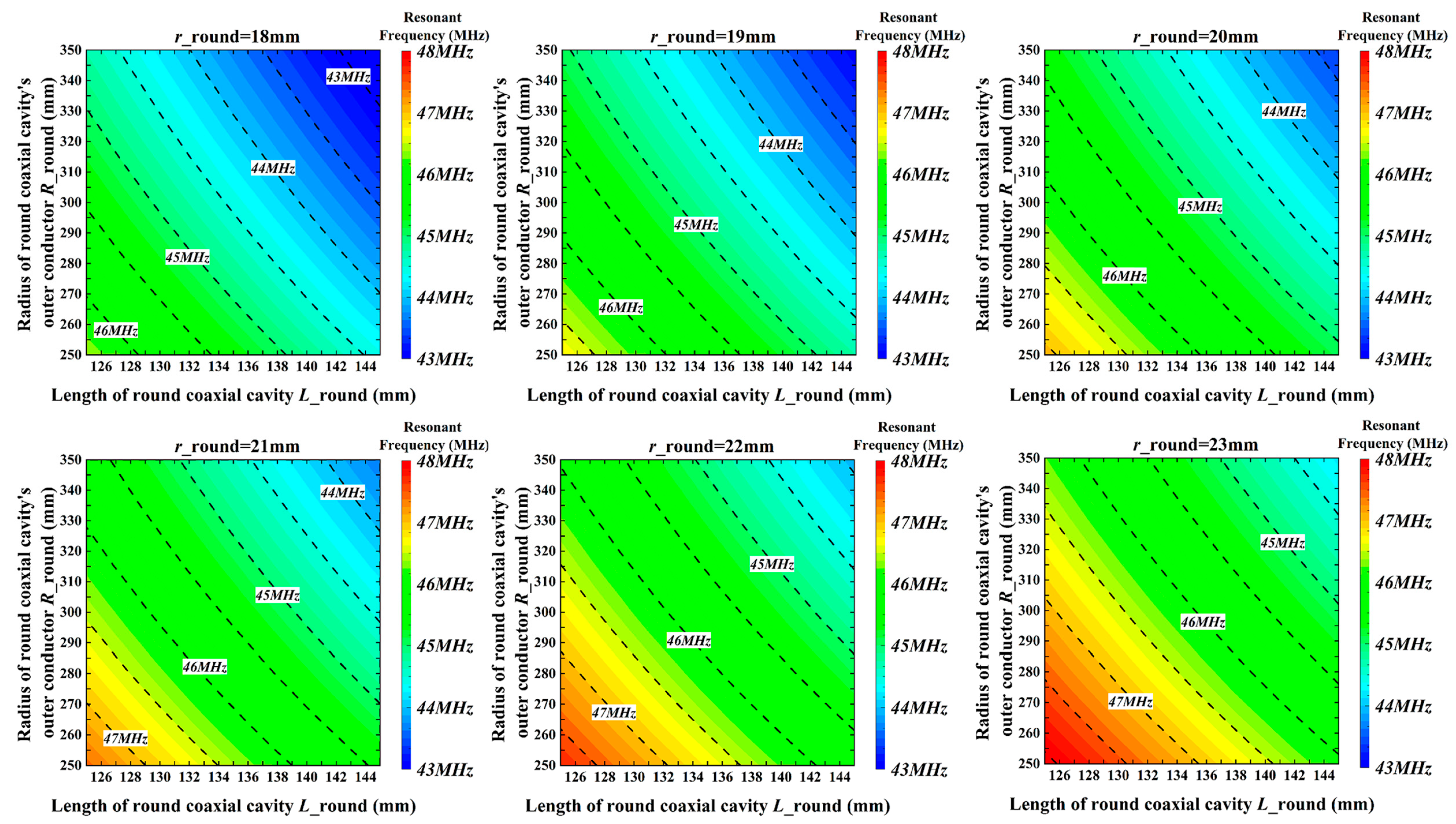
The main structural parameters that can be adjusted in the round coaxial resonant cavity part are the inner conductor radius ric, the outer conductor radius roc, and the length L. The effect of these three structural factors on the resonant frequency of the cavity computed using 3D electromagnetic field numerical simulation software is shown in Figure 6. The RF cavity resonant frequency is smaller when ric is larger, roc is smaller, and L is shorter. When ric is certain, roc is roughly inversely proportional to L at the same resonant frequency. Therefore, it should be avoided that the length L of the round coaxial resonator is too short, which leads to a sharp increase in the radius roc of the outer conductor of the round coaxial resonator.
In order to further determine the selection of each structural parameter of the round coaxial resonator, the effect of these parameters on the unloaded quality factor Q0 of the cavity is calculated. Figure 7 shows the effect of roc and L on the magnitude of the unloaded quality factor of the RF cavity for ric = 20 mm. It can be determined that the larger roc and L are, the larger the Q0 value of the RF cavity is, and different Q0 values can be taken at the same resonant frequency.
The equivalent circuit method is used to find the L corresponding to different roc at ric = 20 mm and the same resonant frequency, and the surface area size of the round coaxial cavity corresponding to each set of data and the unloaded quality factor are calculated by using 3D electromagnetic field simulation software. According to Figure 8, it is observed that at the same resonant frequency, the smaller L is, the larger the surface area of the cavity, and the larger the unloaded quality factor Q0. The surface area of the round coaxial resonator is related to the vacuum degree of the cavity; thus, the cavity design needs to follow the principle of minimizing the surface area of the cavity. This requirement works in the opposite way to the selection of the quality factor. Furthermore, it is established that L is inversely related to roc. In summary, choosing a smaller L will result in a larger Q0 but also lead to an overly large roc and surface area of the cavity. Conversely, selecting a larger L, although it minimizes the surface area of the cavity as much as possible and achieves a smaller roc, necessitates a reduction in the Q0 of the cavity. Consequently, the above influencing factors are considered in the actual design, and an appropriate value is chosen as a compromise based on demand.
4.4. Numerical Calculation of Electromagnetic Fields of the RF Cavity
The SIR structure is introduced to realize the miniaturized design of the RF cavity, and the 3D electromagnetic field numerical simulation software is used to compute the electromagnetic field distribution and resonant frequency of the RF cavity. After determining the boundary conditions of the cavity, the calculation results can be obtained by using the eigenmode solution method.
Since the RF cavity can be viewed as consisting of several segments of transmission lines with different characteristic impedances and a normalized resonator length of 0.42, the impedance ratio can be calculated to be 0.117. However, the characteristic impedance of the Dee and Stem is actually a variable, especially in the Dee region, where the characteristic impedance can be viewed as a function. So, shortening the quarter-wavelength resonator to the desired size is not purely dependent on the contribution of the discontinuity alone, and its impedance ratio RZ will fluctuate compared to the theoretically calculated value 0.117.
From Figure 9, it can be seen that the electric field is mainly distributed at the Dee, which is called the capacitive region, while the magnetic field is mainly distributed at the Stem, which is called the inductive region. Where the electric field is the strongest at the edge of the Dee near the center area, here the magnetic field is the weakest, and where the magnetic field is the strongest at the end of the Stem, here the electric field is the weakest. The distribution of the electromagnetic field in the cavity can also be used as a reference for the design of subsequent water-cooled structures.
5. Calculation and Verification of the RF Cavity for 11 MeV Superconducting Cyclotrons
5.1. Calculation and Verification of the RF Cavity with Different Structural Parameters
After determining all the circuit parameters, the transcendental equation is substituted and the resonance frequency of the circuit is calculated by the iterative method and also utilizing the numerical simulation software to calculate the resonance frequency of the RF cavity. The results obtained by the two calculation methods are compared and verified, and the errors between them are within the acceptable range. At the same time, the influence trend of the structural parameters of the RF cavity on the resonant frequency is determined.
The effect of the structural parameters of the round coaxial resonator on the resonant frequency of the cavity is shown in Figure 10, where it can be seen that the longer the length, the larger the radius of the outer conductor, and the smaller the radius of the inner conductor, the smaller the resonant frequency of the RF cavity. At the same time, it can be seen that the numerical calculation results and the equivalent circuit calculation results are consistent and show good correlation; only the change in the radius of the inner conductor of the round coaxial will produce a relatively large error; the maximum error reaches about 2.7%. The main reason is that changing the radius of the inner conductor of a round coaxial resonator results in a change in the dimensions of the transition coaxial resonator part. When the dimensions of the rectangular part of the transition coaxial and the dimensions of the round part are similar, the error in the results of the characteristic impedance of the transition coaxial calculated by using the empirical formula is small. However, when there is a large difference between the dimensions of the rectangular part and the round part, the results obtained from the empirical formula tend to produce certain errors, which can eventually result in the generation of resonant frequency calculation errors. This has been taken into account in the design when modeling based on the target frequency, so that the error at the target frequency is small, about 0.1%.
The effects of changing the dimensions of some structure parameters of the transition coaxial transmission line and the rectangular coaxial transmission line on the resonance frequency can be observed in Figure 11 and Figure 12. It can be seen that the results of the numerical simulation calculations are in good agreement with the results of the equivalent circuit model. When the transition coaxial length is longer and the outer conductor radius is larger, the resonant frequency of the cavity is smaller. For the rectangular coaxial transmission line, the longer the length and the lower the height, the lower the resonant frequency of the RF cavity. The overall maximum error is around 1% and the error at the target frequency is about 0.13%.
5.2. Analysis of the RF Cavity Based on Multiple Linear Regression Models
The 11 MeV superconducting cyclotron adopts a modular design, and according to the foregoing, it is known that the only parameters available for extensive changes after the preliminary design is completed are the structural parameters of the round coaxial resonant cavity, including the inner conductor radius ric, the outer conductor inner radius roc, and the cavity length L. The effect of each of these three parameters on the resonant frequency of the RF cavity is shown in Figure 10. In order to determine the relationship between these three structural parameters and the cavity resonance frequency, and to obtain the importance of the influence of these three variables on the cavity resonance frequency, a multiple linear regression model can be introduced.
In multiple regression, the main goal is to relate the dependent variable y to more than one independent or predictor variable. Multiple linear regression analysis provides a good fit and prediction of the relationship between multiple sets of independent variables and the corresponding dependent variables. It also reduces the possibility of overfitting that occurs in simple linear regression analysis. The general multiple linear regression model equation is [26]:
where is the estimated value of observation Y; , , … denote k regression coefficients; X1, X2, …, Xk represent k explanatory variables; and ε is a random error term that explains the variation in the observation Y caused by the random variable, where E(ε) = 0 and V(ε) = σ2 and ε~N(0, σ2). In this paper, there are three main structural parameter variables (k = 3), where Y is the RF cavity resonance frequency f, X1 corresponds to ric, X2 corresponds to roc, and X3 corresponds to L.
In order to assess the effectiveness of the regression model in predicting the observation Y, the Root Mean Square Error (RMSE) and the Goodness of Fit, R2, were chosen to test and assess the effectiveness and accuracy of the model. Where RMSE is used to assess the deviation between actual and predicted values and R2 is used to measure the degree of fit of the regression model, the respective expressions are [27]:
where yi is the true value, is the predicted value, and is the sample mean.
Table 2 shows the results after fitting the data obtained by numerical calculation and equivalent circuit calculation using the multiple linear regression analysis method, including RMSE, R2, and regression equations, where the smaller the RMSE and the closer the R2 is to 1, the better the model’s predictive accuracy. The regression equation shows that ric and L have a significant impact on the resonance frequency. Conversely, roc’s effect is less pronounced. If ric increases significantly, widening the magnet yoke opening becomes necessary. Thus, changes to ric are kept within the rectangular cavity’s height limits. By adjusting ric and L, the resonant frequency of the RF cavity can vary widely. Altering roc leads to a narrower frequency adjustment. Therefore, in further cavity design and optimization, the cavity resonant frequency can be roughly adjusted by adjusting the length of the round coaxial cavity L. After determining the resonant frequency adjustment range, the regression equation can be used to accurately calculate the available range for moving the short-circuit end. In addition, the resonant frequency fine-tuning structure design of the RF cavity can refer to the influence of the outer conductor inner radius roc on the resonant frequency.
Figure 13 shows the effects of the round cavity length L on the resonant frequency when ric = 20 mm and roc = 240 mm. It illustrates a high degree of fit between numerical simulation and equivalent circuit calculations. The errors in the prediction results at the target frequency for both models do not surpass 1%. They remain under 0.3%, satisfying the engineering design’s predictive needs.
6. Conclusions
The miniaturization of the resonator is achieved by introducing SIR into the RF cavity of a cyclotron, and the equivalent circuit method is used to simplify and equate the complex RF cavity so as to realize further analysis. The computational results show that the error of the equivalent circuit method and the numerical simulation calculation method can be up to 0.1% at the target frequency. In addition, multiple linear regression analysis can be used to predict the resonance frequency under multiple parameters, and the error of the results is basically kept within 1%. Therefore, a combination of the two methods can greatly simplify the design process and ease the design of the RF cavity of the cyclotron, save computational time, and be suitable for engineering applications.
Author Contributions
Conceptualization, W.-S.W. and Z.-F.H.; methodology, Y.W.; software, Y.W.; validation, Z.-F.H. and W.-S.W.; formal analysis, Z.-F.H., Y.W. and H.-F.Y.; investigation, P.-P.Z., Y.W. and Z.-F.H.; resources, Z.-F.H.; data curation, Y.W., H.-F.Y. and P.-P.Z.; writing—original draft preparation, Y.W.; writing—review and editing, Z.-F.H.; visualization, Y.W. and H.-F.Y.; supervision, W.-S.W. and Z.-F.H.; project administration, Z.-F.H.; funding acquisition, W.-S.W. and Z.-F.H. All authors have read and agreed to the published version of the manuscript.
Funding
This research was supported by the Major Development Project of the Shanghai Institute of Applied Physics, Chinese Academy of Sciences under Grant Y951011031.
Institutional Review Board Statement
Not applicable.
Informed Consent Statement
Not applicable.
Data Availability Statement
The data that support the findings of this study are available from the corresponding author upon reasonable request.
Acknowledgments
The authors would like to thank colleagues Weng-Zhuang Lv of the Shanghai Institute of Applied Physics for their help with the article.
Conflicts of Interest
The authors declare no conflicts of interest.
References
- Qaim, S.M. The present and future of medical radionuclide production. Radiochim. Acta 2012, 100, 635–651. [Google Scholar] [CrossRef]
- Qaim, S.M.; Spahn, I. Development of novel radionuclides for medical applications. Label. Compd. Radiopharm. 2018, 61, 126–140. [Google Scholar] [CrossRef] [PubMed]
- Schmor, P.W.; Vancouver, B.C. Review of cyclotrons for the production of radioactive isotopes for medical and industrial applications. Rev. Accel. Sci. Technol. 2011, 4, 103–116. [Google Scholar] [CrossRef]
- Qaim, S.M. Nuclear data for medical radionuclides. J. Radioanal. Nucl. Chem. 2015, 305, 233–245. [Google Scholar] [CrossRef]
- Synowiecki, M.A.; Perk, L.R.; Nijsen, J.F.W. Production of novel diagnostic radionuclides in small medical cyclotrons. EJNMMI Radiopharm. Chem. 2018, 3, 3. [Google Scholar] [CrossRef] [PubMed]
- McQuade, P.; Rowland, D.J.; Lewis, J.S.; Welch, M.J. Positron-emitting isotopes produced on biomedical cyclotrons. Curr. Med. Chem. 2005, 12, 807–818. [Google Scholar] [CrossRef] [PubMed]
- Gavela, D.; Calero, J.; García-Tabarés, L.; Guirao, A.; Obradors-Campos, D.; Oliver, C.; Pérez, J.M. Calculation and design of a RF cavity for a novel compact superconducting cyclotron for radioisotope production (AMIT). In Proceedings of the International Particle Accelerator Conference (6th), Richmond, VA, USA, 3–8 May 2015; pp. 3055–3057. [Google Scholar]
- Smirnov, V.; Vorozhtsov, S. Modern compact accelerators of cyclotron type for medical applications. Phys. Part. Nucl. 2016, 47, 863–883. [Google Scholar] [CrossRef]
- Munilla, J. Compact accelerators for radioisotope production: The AMIT project. In Proceedings of the Academia-Industry Event on Superconductivity for Accelerators for Medical Applications, Madrid, Spain, 24–25 November 2016. [Google Scholar]
- Makimoto, M.; Yamashita, S. Quarter-Wavelength-Type SIR. In Microwave Resonators and Filters for Wireless Communication: Theory, Design and Application; Springer Series in Advanced Microelectronics; Springer: Berlin/Heidelberg, Germany, 2001; Volume 4, pp. 19–39. [Google Scholar]
- RF Module Users Guide, COMSOL 5.3; COMSOL AB: Stockholm, Sweden, 2018; pp. 77–172.
- Dong, T.L.; Zhan, L.M.; Hong, Y.M.; Fan, M.W. Cyclotron cavity analysis based on field circuit model. Nucl. Instrum. Methods Phys. Res. Sect. A Accel. Spectrometers Detect. Assoc. Equip. 2003, 513, 631–634. [Google Scholar] [CrossRef]
- Zhan, L.M.; Hong, Y.M.; Dong, T.L. Application of two-dimensional boundary element method to resonant frequency problem of accelerator cavity. At. Energy Sci. 2004, 38, 10. [Google Scholar]
- Benedicto, J.; Aouidad, M.H.; Rius, E.; Favennec, J.F.; Annaig, M.G.; Manchec, A. Analytical modeling of three-section coaxial stepped impedance resonators for the design of compact Tx bandpass filters. IEEE Trans. Microw. Theory Tech. 2022, 70, 4140–4155. [Google Scholar] [CrossRef]
- Benedicto, J.; Rius, E.; Bonizec, A.; Favennec, J.F.; Bernal, A.B.; Annaig, M.G. Quarter-Wavelength and Open-End Half-Wavelength Four-Section Coaxial Stepped Impedance Resonators for High-Power Space Bandpass Filters. IEEE Trans. Microw. Theory Tech. 2023. [Google Scholar] [CrossRef]
- Pozar, D.M. Transmission Line Theory. In Microwave Engineering; Wiley: Hoboken, NJ, USA, 2011; pp. 48–95. [Google Scholar]
- Srivastava, G.P.; Gupta, V.L. Microwave Transmission Lines. In Microwave Devices and Circuit Design; Prentice-Hall of India Private Limited: New Delhi, India, 2006; pp. 62–101. [Google Scholar]
- Wang, X.; Deslandes, D.; Feng, W.; Chen, H.; Che, W. Coupling analysis of adjacent substrate-integrated waveguides based on the equivalent transmission line model. IEEE Trans. Microw. Theory Tech. 2020, 68, 1347–1354. [Google Scholar] [CrossRef]
- Mohamadian, M.; Afarideh, H.; Ghergherehchi, M. Accurate electromagnetic simulation and design of cyclotron cavity. IEEE Trans. Nucl. Sci. 2016, 64, 809–815. [Google Scholar] [CrossRef]
- Wadell, B.C. Physical Transmission Lines. In Transmission Line Design Handbook; Artech House Microwave Library: Norwood, MA, USA, 1991; pp. 45–177. [Google Scholar]
- Genderen, W.V.; Van Der Heide, J.A.; Bräutigam, W. Calculation of cyclotron rf systems. Nucl. Instrum. Methods Phys. Res. Sect. A Accel. Spectrometers Detect. Assoc. Equip. 1987, 258, 161–169. [Google Scholar] [CrossRef]
- Lee, J.; Ghergherehchi, M.; Shin, S.W.; Kim, H.; Ha, D.; Namgoong, H.; Song, H.S.; Chai, J.S. Design of 83.2 MHz RF cavity for SKKUCY-10 cyclotron. Nucl. Instrum. Methods Phys. Res. Sect. A Accel. Spectrometers Detect. Assoc. Equip. 2019, 939, 66–73. [Google Scholar] [CrossRef]
- Shin, S.; Lee, J.; Lee, B.N.; Ha, D.; Namgoong, H.; Chai, J. Development of the RF cavity for the SKKUCY-9 compact cyclotron. Nucl. Instrum. Methods Phys. Res. Sect. A Accel. Spectrometers Detect. Assoc. Equip. 2015, 795, 276–283. [Google Scholar] [CrossRef]
- Jung, I.S.; An, D.H.; Chai, J.S.; Chang, H.S.; Hong, B.H.; Hur, M.G.; Kang, J.; Kim, S.W.; Kim, Y.S.; Chong, S.P.; et al. Design of KIRAMS-13 RF system for regional cyclotron center. In Proceedings of the 2004 Autumn Meeting of the KNS, Yongpyong, Republic of Korea, 28–29 October 2004; pp. 353–355. [Google Scholar]
- Kim, Y.S.; An, D.H.; Chai, J.S.; Chang, H.S.; Hong, B.H.; Hong, S.S.; Hur, M.G.; Hwang, W.T.; Jung, I.S.; Kang, J.S. New Design of the KIRAMS-13 cyclotron for regional cyclotron center. In Proceedings of the 3rd Asian Particle Accelerator Conference, Gyenogiu, Republic of Korea, 22–26 May 2004; pp. 338–340. [Google Scholar]
- Korkmaz, M. A study over the formulation of the parameters 5 or less independent variables of multiple linear regression. J. Funct. Spaces 2019, 2019, 1526920. [Google Scholar] [CrossRef]
- Chicco, D.; Warrens, M.J.; Jurman, G. The coefficient of determination R-squared is more informative than SMAPE, MAE, MAPE, MSE and RMSE in regression analysis evaluation. PeerJ Comput. Sci. 2021, 7, e623. [Google Scholar] [CrossRef] [PubMed]
Figure 1.
The electrical parameters of the cyclotron Dee’s SIR structure.
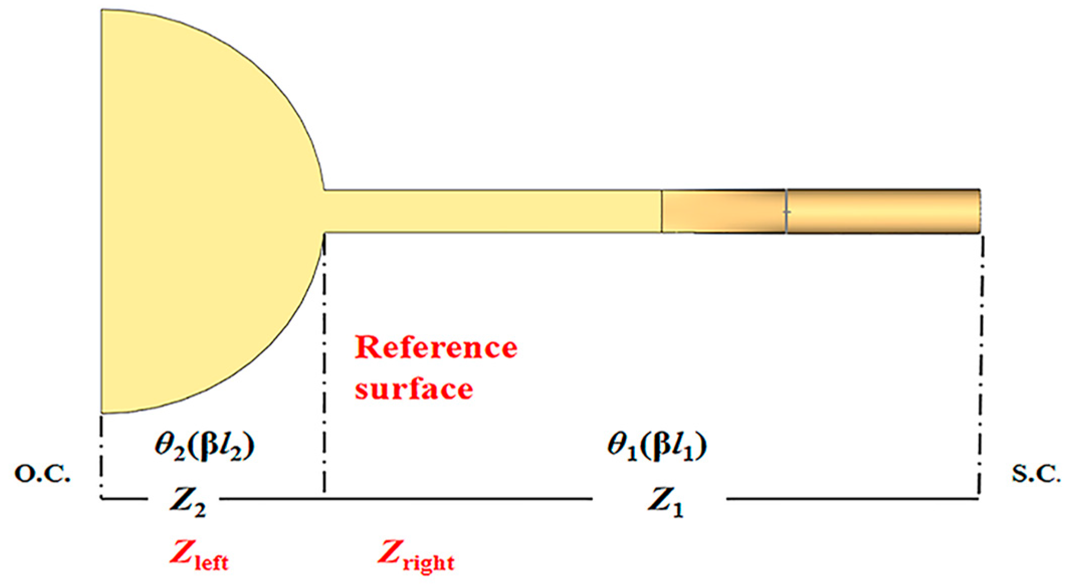
Figure 2.
The equivalent circuit of an 11 MeV superconducting cyclotron’s RF cavity.
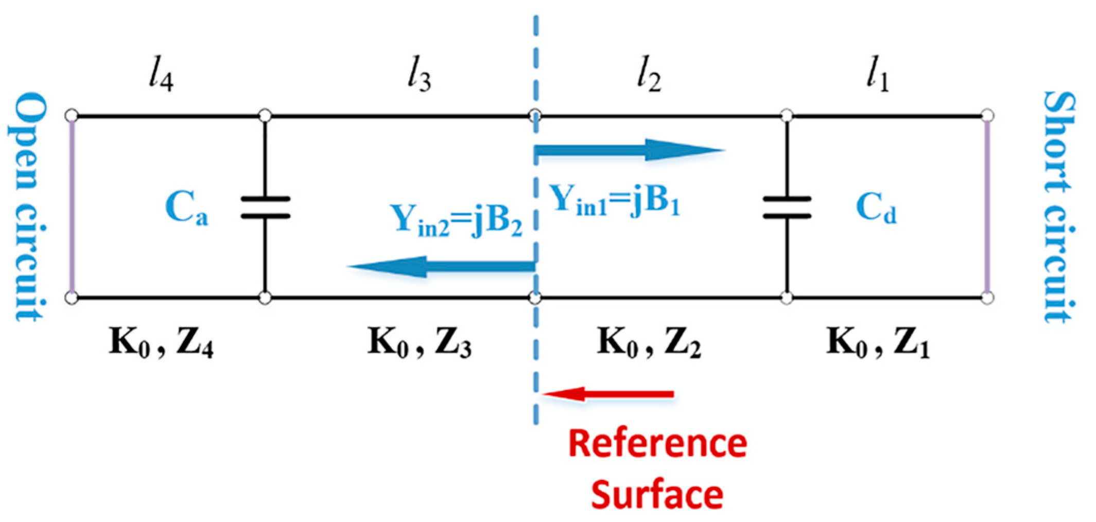
Figure 3.
The RF cavity with different shapes of Dee and Stem structures: (a) rectangular Stem and (b) cylindrical Stem.
Figure 3.
The RF cavity with different shapes of Dee and Stem structures: (a) rectangular Stem and (b) cylindrical Stem.
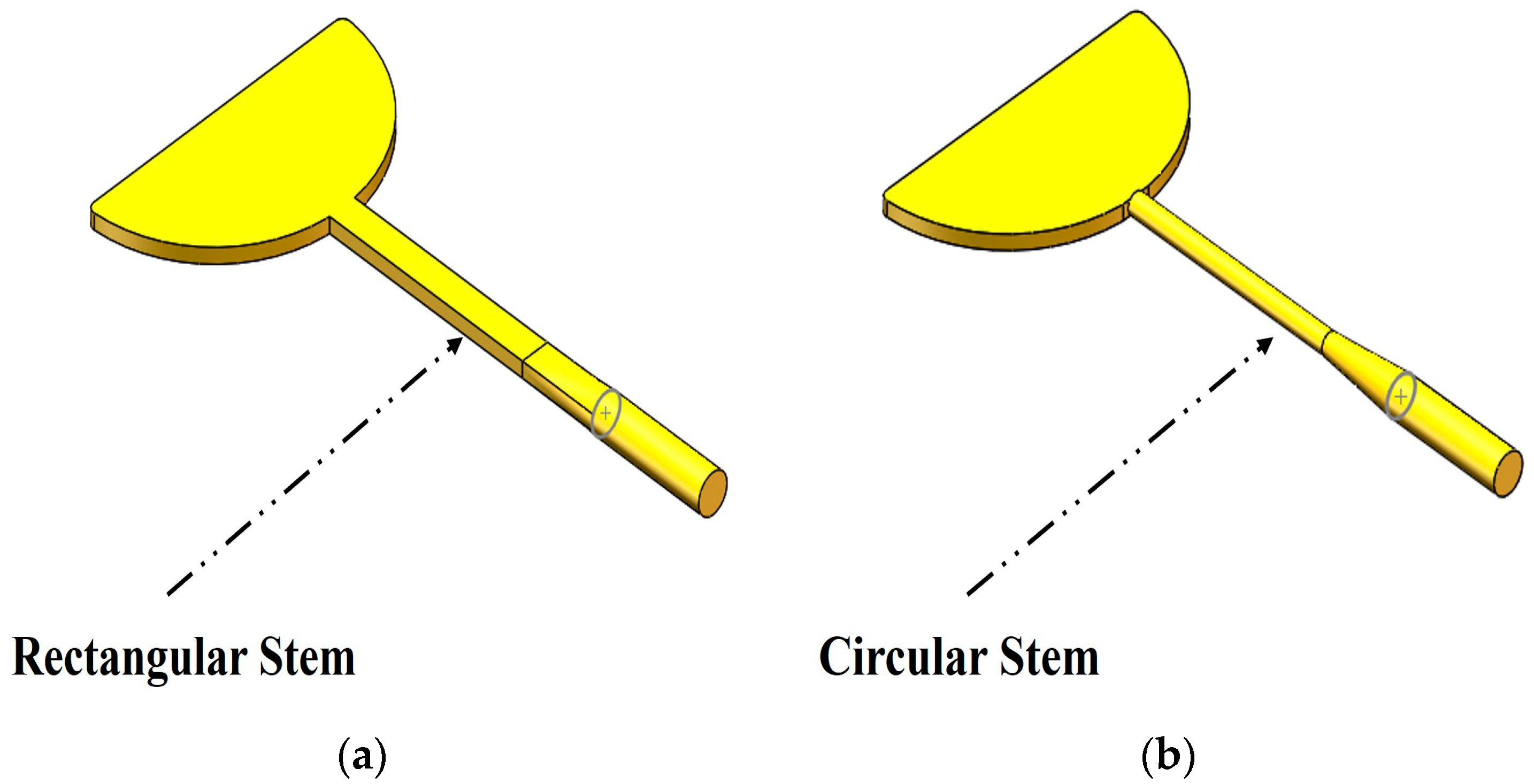
Figure 4.
Circular Stem diameter versus resonant frequency.
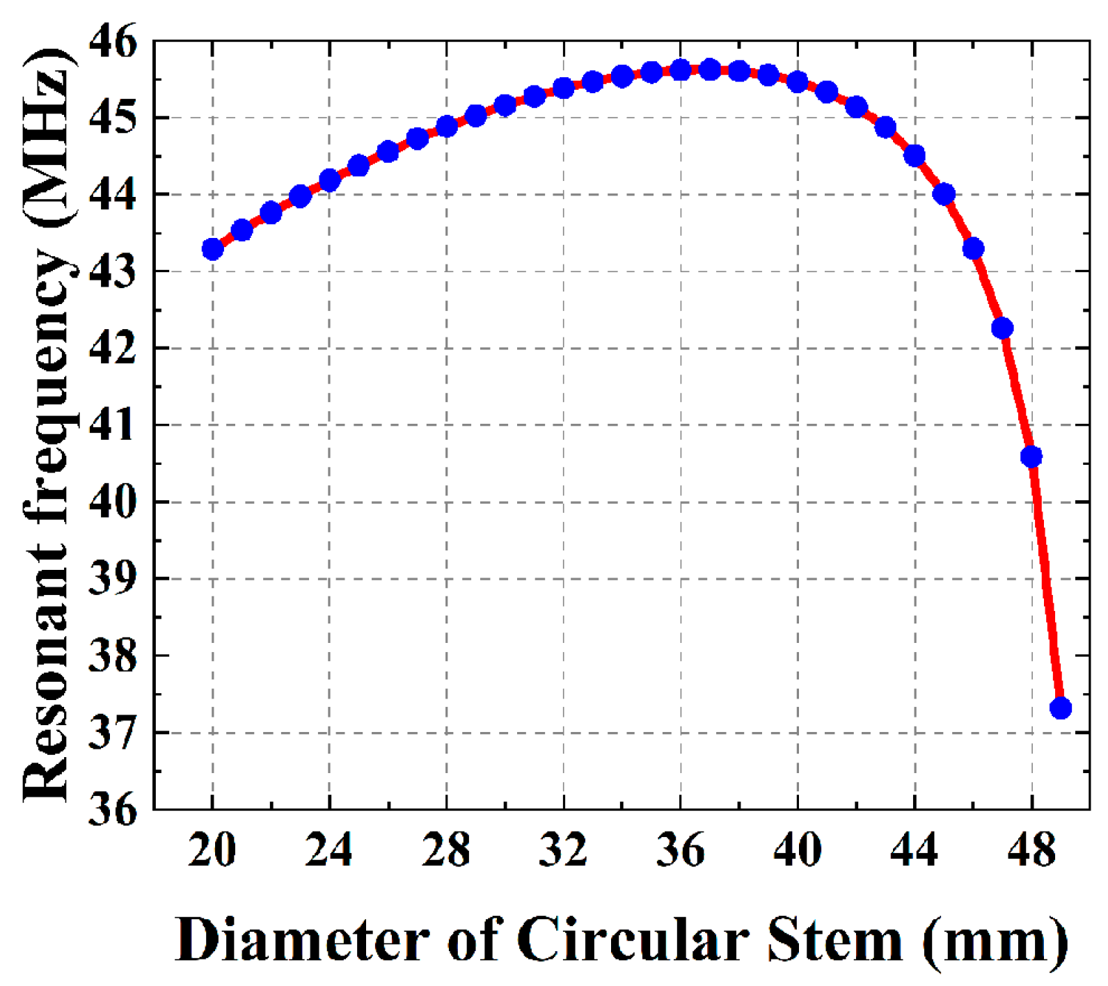
Figure 5.
Chamfer radius at the edge of Dee versus resonant frequency.

Figure 6.
Influence of each parameter of a round coaxial resonator on the resonant frequency of the RF cavity.
Figure 6.
Influence of each parameter of a round coaxial resonator on the resonant frequency of the RF cavity.

Figure 7.
Influence of each parameter of the round coaxial resonator on the unloaded quality factor of the RF cavity.
Figure 7.
Influence of each parameter of the round coaxial resonator on the unloaded quality factor of the RF cavity.
Figure 8.
Effects of different round coaxial resonator lengths on the surface area of the round coaxial resonator and unloaded quality factor at the same resonant frequency.
Figure 8.
Effects of different round coaxial resonator lengths on the surface area of the round coaxial resonator and unloaded quality factor at the same resonant frequency.
Figure 9.
Field distribution of the RF cavity: (a) electric field and (b) magnetic field.

Figure 10.
Round coaxial line parameters versus resonant frequency of cavity. (a) Line length, (b) radius of line outer conductor, (c) radius of line inner conductor radius.
Figure 10.
Round coaxial line parameters versus resonant frequency of cavity. (a) Line length, (b) radius of line outer conductor, (c) radius of line inner conductor radius.
Figure 11.
Impact of transition coaxial line parameters on the resonant frequency of the cavity. (a) Line length and (b) radius of line outer conductor.
Figure 11.
Impact of transition coaxial line parameters on the resonant frequency of the cavity. (a) Line length and (b) radius of line outer conductor.
Figure 12.
Impact of rectangular coaxial line parameters on the resonant frequency of cavity. (a) Line length and (b) line height.
Figure 12.
Impact of rectangular coaxial line parameters on the resonant frequency of cavity. (a) Line length and (b) line height.
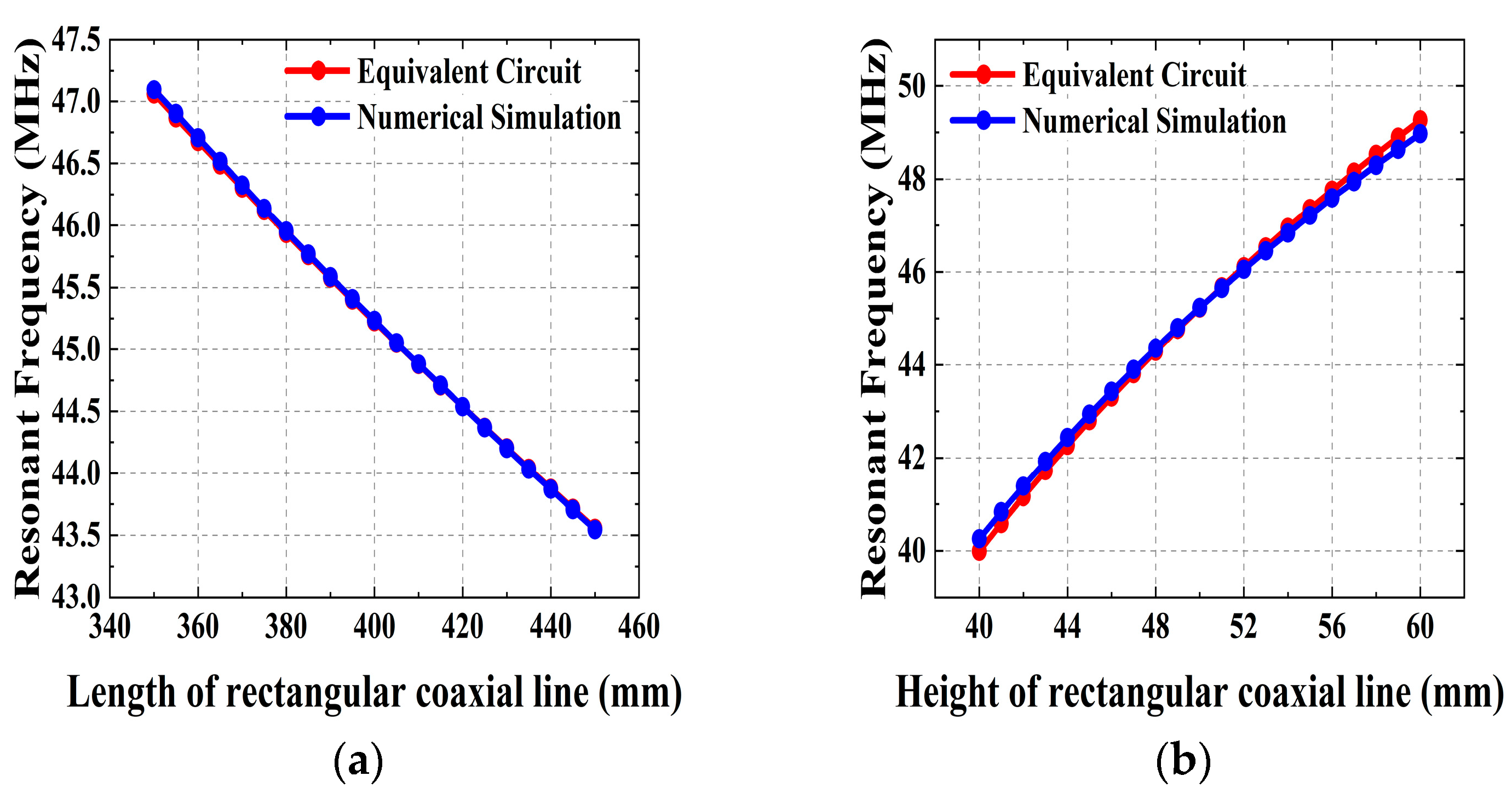
Figure 13.
Performance of the RF cavity resonant frequency prediction based on multiple linear regression models.
Figure 13.
Performance of the RF cavity resonant frequency prediction based on multiple linear regression models.


Table 1.
Conceptual design parameters for an 11 MeV superconducting cyclotron’s RF cavity.
| Cyclotron Parameters | Value |
|---|---|
| Energy | 11 MeV |
| Resonant Frequency | 45.026 MHz |
| Harmonic No. | 1 |
| Extraction Radius | 161 mm |
| Dee Voltage | 30 kV |
| Coupling Type | Inductive |
Table 2.
Performance of the RF cavity resonant frequency prediction based on multiple linear regression models.
Table 2.
Performance of the RF cavity resonant frequency prediction based on multiple linear regression models.
| Method | RMSE | R2 | Regression Equation |
|---|---|---|---|
| Numerical simulation | 0.040 | 0.998 | f = 57.573 + 0.3172 × ric − 0.0174 × roc − 0.1005 × L |
| Equivalent circuit | 0.052 | 0.998 | f = 56.856 + 0.3995 × ric − 0.0183 × roc − 0.1054 × L |
Disclaimer/Publisher’s Note: The statements, opinions and data contained in all publications are solely those of the individual author(s) and contributor(s) and not of MDPI and/or the editor(s). MDPI and/or the editor(s) disclaim responsibility for any injury to people or property resulting from any ideas, methods, instructions or products referred to in the content. |
© 2024 by the authors. Licensee MDPI, Basel, Switzerland. This article is an open access article distributed under the terms and conditions of the Creative Commons Attribution (CC BY) license (https://creativecommons.org/licenses/by/4.0/).
Share and Cite
MDPI and ACS Style
Wu, Y.; He, Z.-F.; Wan, W.-S.; Zheng, P.-P.; Yu, H.-F. Research and Design of the RF Cavity for an 11 MeV Superconducting Cyclotron. Appl. Sci. 2024, 14, 3549. https://doi.org/10.3390/app14093549
AMA Style
Wu Y, He Z-F, Wan W-S, Zheng P-P, Yu H-F. Research and Design of the RF Cavity for an 11 MeV Superconducting Cyclotron. Applied Sciences. 2024; 14(9):3549. https://doi.org/10.3390/app14093549
Chicago/Turabian StyleWu, Yue, Zi-Feng He, Wei-Shi Wan, Pan-Pan Zheng, and Hua-Fei Yu. 2024. "Research and Design of the RF Cavity for an 11 MeV Superconducting Cyclotron" Applied Sciences 14, no. 9: 3549. https://doi.org/10.3390/app14093549
Note that from the first issue of 2016, this journal uses article numbers instead of page numbers. See further details here.