Review

Enhancing Deposit Exploitation Efficiency Utilizing Small-Diameter Radial Boreholes via Hydraulic Drilling Nozzles for Optimal Resource Recovery

by
Przemyslaw Toczek
* and
Rafal Wisniowski
Drilling and Geoengineering Department, Drilling, Oil and Gas Faculty, AGH University of Krakow, 30-059 Krakow, Poland
*
Author to whom correspondence should be addressed.
Appl. Sci. 2024, 14(9), 3552; https://doi.org/10.3390/app14093552
Submission received: 9 January 2024 / Revised: 12 April 2024 / Accepted: 19 April 2024 / Published: 23 April 2024
(This article belongs to the Section Energy Science and Technology)

Abstract

:
The exploration and development of new hydrocarbon deposits is facing increasing challenges as the global shift to renewable energy sources, such as shallow geothermal deposits, wind farms, and photovoltaics, reduces the dependence on hydrocarbons. To navigate this evolving landscape, it becomes crucial to find solutions that optimize the energy extraction efficiency while maximizing the use of hydrocarbon deposits. This requires exploring opportunities in existing fields and wells, including those slated for decommissioning. This article discusses the potential for extracting resources from seemingly depleted fields, where some 60–70% of the resources remain unrecoverable due to low reservoir energy. Meeting this challenge requires the implementation of secondary and tertiary EOR methods that involve the introduction of external energy to increase reservoir pressure and enhance resource recovery. One of the proposed innovative tertiary methods involves reaming the reservoir using multiple small-diameter radial boreholes generated by a hydraulic drilling nozzle. This strategy is designed to intensify the contact between the production hole and the reservoir layer, resulting in increased or commenced production in certain cases. The described method proves to be a practical application in hydrocarbon deposits, offering the dual benefits of mitigating environmental pollution by eliminating the need for drilling new boreholes and providing a cost-effective means of accessing resources in decommissioned deposits with insufficient reservoir energy for self-exploitation. Another article points out the design variation of a hydraulic drilling nozzle tailored specifically for reaming a reservoir layer. Taking the above into account, this article provides very practical information for future projects in which paths should be sought for the design and development of hydraulic wellheads, among other things, in order to intensify the production from hydrocarbon deposits.

1. Introduction

The diversification of oil supplies and potential price increases in the global market call for a reassessment of enhanced oil recovery (EOR) methods to increase production. As such, there is an urgent need to explore and implement solutions focused on creating new technologies or applying existing ones, deepening our understanding of the underlying phenomena, and generally enhancing knowledge and practices related to field production. Escalating global expenses associated with making hydrocarbon deposits accessible are compelling companies to invest in innovative technologies [1]. However, each new method presents unique challenges in terms of design, decision-making, and execution, requiring thorough consideration before application. This involves economic and logistical comparisons with conventional drilling methods [2]. The overarching objective of these endeavors is to decrease the well-drilling costs while maximizing the exploitation of existing deposits. Given the increasing importance of supporting the decision-making process, there is a critical need to minimize the risk associated with investments, especially concerning technologies like directional drilling or hydraulic fracturing. This is crucial to avoiding ill-considered decisions and ensuring a sensible approach to technological progress in the oil industry.
The search for innovative solutions to enhance extraction has given rise to the development of radial borehole drilling, executed from a base hole using the high-pressure jet energy of hydraulic radial drilling nozzles. The unique characteristics of this technology, specifically, the capability to achieve an exceptionally short radius of curvature, of approximately 30 cm, and the remarkable increase in the angle of curvature of the hole (100–250°/30 m), have led to the classification term URRS (Ultrashort-Radius Radial System) [3,4,5]. Radial drilling finds application in both existing and new production as well as exploration wells [1,6,7]. In this context, “radial drilling” does not solely refer to a small radius of curvature but emphasizes the ability to drill in various directions at the same level. Typically, two to four small-diameter boreholes are drilled, depending on the deposit structure, layer characteristics, and production requirements. The exceptionally small radius of curvature and the correspondingly compact dimensions of the drilling set necessitate the application of unconventional drilling techniques. Various methods were considered, but hydraulic radial drilling, utilizing a high-pressure liquid jet expelled from the nozzles of the rotary head, emerged as the most effective. This approach enables a remarkably high concentration of fluid energy per unit area of rock, thereby facilitating hydraulic radial drilling.

2. Development of the Radial Drilling Technology

Radial drilling represents an unconventional technique employing a small-diameter steel conduit, such as a capillary or a coiled tubing, to bore a hole with a diameter ranging from 50 to 60 mm and a length of up to 200 m. This process utilizes a high-energy fluid stream propelled through a nozzle at elevated pressures [6,8,9]. Economically, the radial drilling technology proves effective for drilling horizontal channels extending up to 900 m from an existing vertical borehole. It becomes particularly valuable when other tertiary methods prove ineffective or to enhance the efficiency of existing Enhanced Oil Recovery (EOR) methods [6,10,11,12]. The concept of processing materials with a high-pressure water jet dates back to the 1960s, with applications ranging from cutting metals, rocks in mining, and ceramics, to cutting plastics in shipbuilding and the automotive industry. These techniques vary in water pressure, incorporating abrasive agents to aid the process. As high-pressure technology advanced, covering more industries, attempts were made in the late 1960s to introduce this technique into the oil industry. However, technological limitations and capabilities at that time temporarily hindered its development. In subsequent years, scientific studies by Maurer and others contributed to the refinement of this drilling technique. Dickinson [3] introduced a borehole drilling system with a 0.1 m diameter and lengths ranging from 30.48 to 60.96 m, utilizing a hydroturbine and achieving drilling speeds of 30.5–60.9 mm/s. Dickinson [13] employed a 0.032 m diameter coiled tubing, resulting in boreholes ranging from 0.87 to 52.2 m in length after passing through a casing window, resulting in a tenfold increase in oil production. Presently, the successful drilling of multiple radial wells from the main well using a drum-wound conductor [14] demonstrates their contribution to increased reservoir production and improved reservoir ratios, while minimizing damage to the near-wellbore zone. The expense associated with drilling and reaching a depth of 2500 m using conventional methods, such as rotary methods with bottom and top drives, surpasses EUR 7–8 million. Notably, standard-diameter directional drilling accounts for at least 40% of this cost. For planned new wells, a pivotal challenge in the decision-making process lies in selecting the spatial trajectory for the horizontal part. The efficacy of applying the directional drilling technology hinges on the accuracy of the design and execution of the assumed well trajectory [15,16]. Considering the anisotropy of reservoirs’ physical properties, opting for an optimal trajectory is crucial to ensuring an efficient inflow of hydrocarbons. The radial wells proposed in this article, drilled with a rotary hydraulic nozzle, offer a solution that enables the intensification of production and enhances the connection between the well and the reservoir. Conversely, when dealing with wells exhibiting low or zero productivity, a decision must be made regarding either decommissioning them or undertaking costly intensification procedures. Hydraulic radial boreholes will help develop the production from reservoirs without drilling new horizontal wells in the reservoir zone.
The solution to the challenges outlined and the growing demand lies in a technology that enables the drilling of multiple small-diameter radial lateral wells from an existing drilled and cased well [17]. With the cost of radial drillings (four boreholes) from a single production zone, covering a range of up to 200 m from the main vertical hole, being less than EUR 600,000, this technology facilitates the acquisition of valuable reservoir data. This, in turn, mitigates the risk of erroneous decisions and unnecessary financial losses amounting to millions of euros. The proposed technology not only provides a cost-effective approach but also allows for the redevelopment of old and decommissioned deposits with a depletion rate of 30–40%. When combining radial drilling with hydraulic fracturing in low-permeability deposits, there is a potential to significantly increase the volume of extractable resources from the reservoir layer [7]. Particularly in favorable lithological conditions, radially reaming the production seam up to 200 m from the main well enables the inflow of reservoir fluid that was previously inaccessible due to insufficient reservoir energy. The hydraulic rotary head described in this article, utilizing the energy of the jet for drilling small-diameter boreholes, facilitates precise decision-making regarding the reconstruction, intensification treatments, or the decommissioning of the well. In instances where lithological conditions are favorable, the drilled wells can enhance the inflow of reservoir fluid to such an extent that expensive intensification treatments may not be necessary.

3. Stages of Drilling a Radial Borehole

The hydraulic radial drilling technique for drilling small-diameter boreholes necessitates a departure from traditional methods of transmitting mechanical energy to the drill bit. This departure includes implementing mechanisms such as rotating drill pipes, torque from a downhole motor, or impact energy generated either mechanically or indirectly through a hydraulic medium. By harnessing the energy of the flowing jet from the nozzles, this method allows for the utilization of hydraulic energy, a direct application that was not previously employed, to hydro-turbine hard rock. The same principle applies when abrasive particles are introduced into the direct excavating fluid, enhancing the impact force on the hydroprobing rock surface. Maurer, in his study, provided an example of developing drilling head solutions using the rock hydro-sanding method [18]. The measure of the energy required to drill a unit volume of rock during the drilling process is termed specific drilling energy. In the case of hydraulic radial drilling, it is more common to refer to the energy used to create a fracture in the rock [18]. This is calculated by dividing the energy by the product of the depth and width of the fracture and the velocity during the fracture-cutting process. In contrast, classical drilling discusses the total specific energy of drilling (TSE), expressed as the sum of the energy of rotational motion, the progressive motion of the drill pipe, and the hydraulic energy necessary to drill a unit volume of rock during the drilling process [2,19,20].
Based on analyses of production data from a specific deposit, as well as on geophysical, petrophysical, and other pertinent analyses, the parameters for reaming the deposit are determined. This includes selecting the appropriate levels within the deposit to be reamed and determining the length and number of radial boreholes to be drilled. These decisions are informed by a comprehensive understanding of the deposit’s characteristics, ensuring that the radial drilling process is tailored to optimize production and reservoir performance. In order to search for a novel solution, the literature was reviewed in terms of requirements and limitations regarding this technology. The main assumptions are compacted in the Figure 1.
The process of drilling a single radial borehole involves the following sequential steps [21,22]:
  • Pulling out the production equipment: the first step is to retrieve the production equipment from the well, along with any existing downhole equipment.
  • Cleaning the borehole: the borehole is then cleaned to prepare it for the subsequent drilling process.
  • Determining the correct depth and orienting the deflector outlet: The correct depth is determined, and the deflector outlet is oriented using appropriate tools, such as a gyroscope. This operation can be performed after fastening the anchor.
  • Casing: Casings are installed on the borehole. A radial borehole drilling set enables drilling a window in the casing for further drilling behind them and includes components such as a deflector, an anchor, and other elements (control section).
  • Fastening the anchor: the anchor is securely fastened in place.
  • Fastening the window cutting tool: a tool for making a window in the casing pipe is attached to the capillary.
  • Making a window in the casing: using the window cutting tool, a window is created in the casing.
  • Pulling out the tool: the window cutting tool is then removed from the well.
  • Arming the capillary: The capillary is equipped with a flexible high-pressure elastic hose with a nozzle and is inserted into the deflector. Drilling is initiated to the specified length using the drilling set.
  • Retracting the drilling set: the drilling set is retracted from the hole while simultaneously flushing the borehole to remove the drill cuttings.
  • Pulling out the drilling set: The drilling set is completely removed from the well. The anchor is unhooked, and if necessary, the orientation of the deflector is changed for drilling another window and borehole.
  • Completing the operation: the final step involves pulling out the entire downhole set and securing the production equipment back into the well.
This detailed sequence outlines the systematic process involved in drilling a single radial well, ensuring precision and efficiency throughout each step of the operation.

4. Cavitation Jet Drilling

Drilling into rock using a continuous fluid stream becomes feasible when surpassing a threshold pressure, which, especially for hard rocks like granite and basalt, can often exceed 200 MPa, representing the rock’s compressive strength limit. However, the high threshold pressure poses challenges due to issues with the seals employed in high-pressure equipment, limiting the applicability of such methods. To circumvent these challenges, solutions involving a jet with pulsating pressure are often utilized, employing devices like jet cannons to momentarily increase the pressure to high values. An alternative approach involves drilling using a continuous cavitation jet, which incorporates gas bubbles. These bubbles contribute to an increase in the backpressure acting on the rock. The pressure induced by a continuous fluid stream can be mathematically expressed by the following equation of the pressure of stagnation P0 in a fluid stream, which can be written using Bernoulli’s equation, describing the relationship between the fluid’s pressure, density, and velocity:
P 0 = P + 1 2 ρ v 2
where
  • P 0 —pressure of stagnation;
  • P —static pressure;
  • ρ—liquid density;
  • v—jet velocity.
This equation demonstrates how the pressure of stagnation ( P 0 ) is composed of the sum of the static pressure ( P ) and the dynamic pressure term, 1 2 ρ v 2 , which is dependent on the density ( ρ ) and the velocity (v) of the fluid jet.
Conn [23] showed that for isothermal compression, the build-up pressure pi produced by the cavitation flux is expressed by Equation (2):
p i = p s 6.35 e x p 2 3 α
where
  • p i —build-up pressure produced by the cavitation flux;
  • p s —saturation vapor pressure;
  • α—parameter influencing the cavitation process (the gas content of the liquid, expressed as the ratio of the partial pressure of the gas to the stagnation pressure at the beginning of bubble destruction).
Conn and Rudy [23] assumed that the angle α varies from 1/6 to 1/10, as shown in Figure 2. In this case, backpressure and stagnation pressure are related by Equation (3). Johnson [24] concluded that stagnation pressures as high as 1380–2700 MPa are produced by cavitating fluxes.
p i = 8 ÷ 124 p s
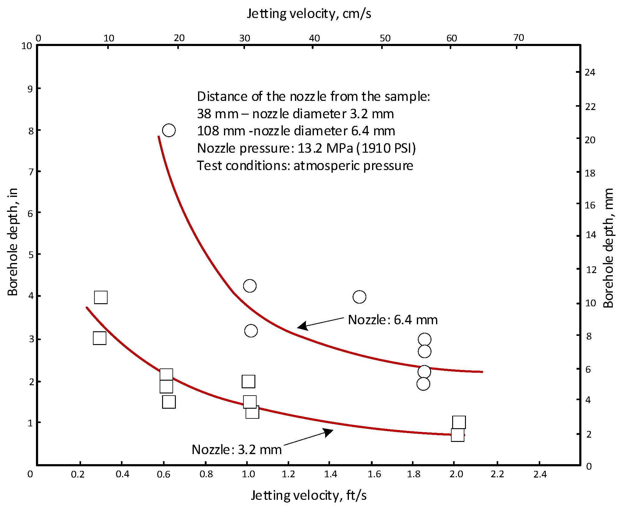
Tests were conducted in hydronautics [25] on coal samples subjected to liquid jet drilling. The tests were carried out at a pressure of 13.2 MPa with a jet diameter of 6.4 mm and a 15 cm/s rate of penetration, as illustrated in Figure 3. Under these conditions, a cutting gap of 6–20 cm in diameter was achieved. The results presented in Table 1 reveal variations in specific energy based on different parameters. Specifically, the specific energy decreased as the rate of penetration (ROP) increased and increased with a larger nozzle diameter. The collected data indicate that the lowest specific energy value was observed when using the smallest nozzle, measuring 1.8 mm, coupled with a maximum ROP of 91.4 cm/s. These findings suggest that there exists an optimal combination of nozzle diameter and rate of penetration speed, resulting in minimized specific energy requirements for the hydraulic drilling of coal samples using a cavitation jet. This information is valuable for optimizing the process and enhancing the efficiency of radial drilling in coal utilizing this technology.
As mentioned earlier, a cavitation jet allows for drilling through rock at lower pressures generated by pumps, even in hard rock, compared to a continuous jet. However, it is important to note that the specific energy required to cut a fracture using a cavitation jet, as discussed by [18], is higher than that needed with a continuous jet. For instance, a continuous jet with a diameter of 0.58 mm, operating at 69 MPa, with ambient pressure equal to the atmospheric pressure, requires 63 J/cm2 to drill into Berea sandstone [26].
In contrast, when using a 6.4 mm diameter cavitation jet drilling at the same ambient pressure, the energy requirement increases significantly to 1390 J/cm2, as shown in Table 1. Part of the increased energy requirement can be attributed to the fact that the cavitation jet produces a fracture with a larger gap of 87 mm, compared to 20 mm, when the jet diameter is larger (6.4 mm versus 0.58 mm). This emphasizes the trade-off between the advantages of reduced pump pressure and the higher specific energy needed when employing a cavitation jet for rock drilling, particularly with large-diameter jets.
Table 1. Data for cavitation hydraulic jet drilling [27].
Test Conditions,
MPa
Jetting Velocity,
cm/s
Width of the Crack,
cm
Length of the Crack,
cm
Stream Power,
kW
Specific Energy per Unit of Crack Volume,
J/cm2
Berea
Sandstone
ATM *9.50.875.4871.81390
3.459.452.303.1871.82390
6.909.451.672.9571.82580
13.809.451.273.0271.82520
20.709.451.431.9171.83980
Indiana
Limestone
ATM *9.451.430.4071.819,000
3.459.451.590.3371.823,000
6.909.451.190.3371.823,000
20.709.451.190.4171.816,200
* ATM means atmospheric pressure.
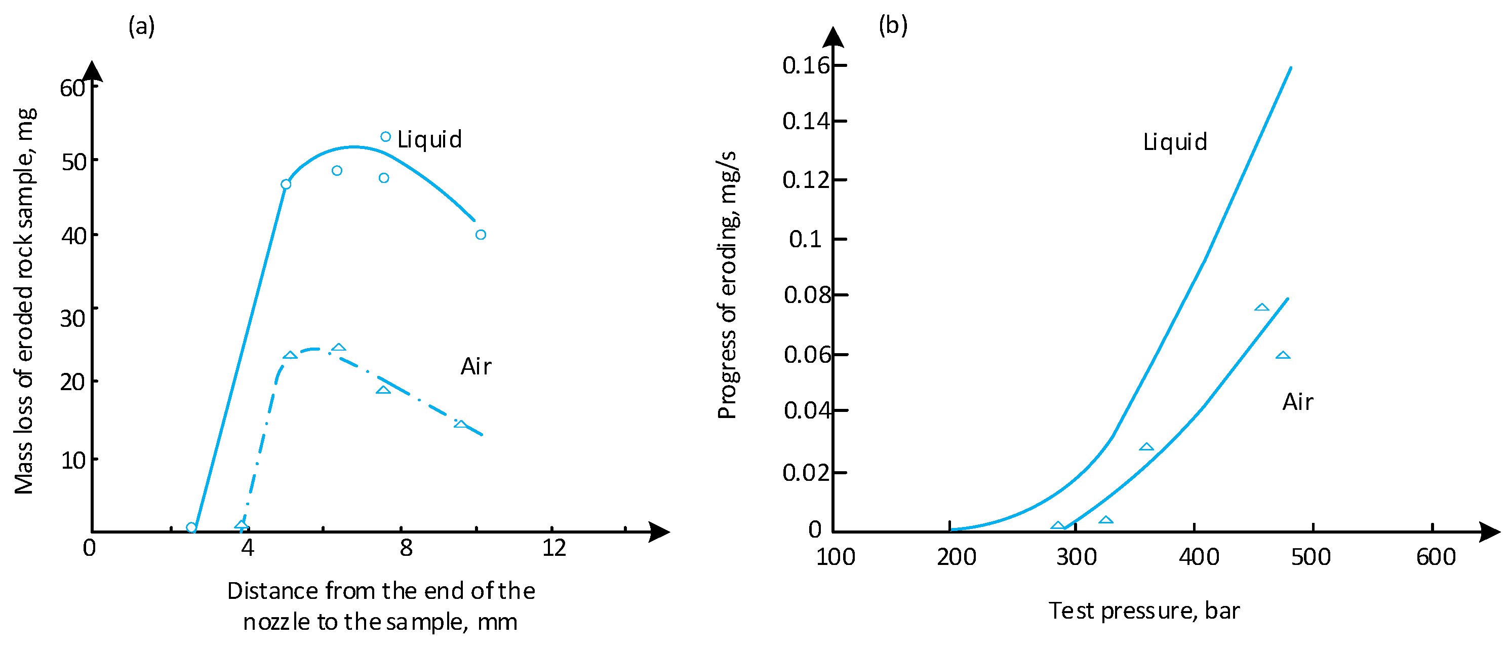
The distance of the nozzle from the rock formation is a crucial factor influencing the quality of the work performed by cavitation jets (Figure 4a,b) [28]. Tests were conducted with cavitation jets operating both submerged and in the air. The results illustrated in Figure 4a indicate that submerged cavitation jets removed approximately twice as much material as cavitation jets operating in the air.
For a cavitation jet submerged in liquid, the optimal distance from the target was determined to be 7.7 cm. In contrast, for a jet operating at atmospheric pressure, the optimum distance was slightly reduced to 6.5 cm. This information emphasizes the significance of the distance between the nozzle and the target in influencing the efficiency of cavitation jet operations.
It is worth noting that the focus of this article is on conducting a study of hydraulic radial drilling using a continuous high-pressure jet, providing valuable insights into the dynamics of the process.

5. Drilling Nozzles Using a Continuous High-Pressure Liquid Stream

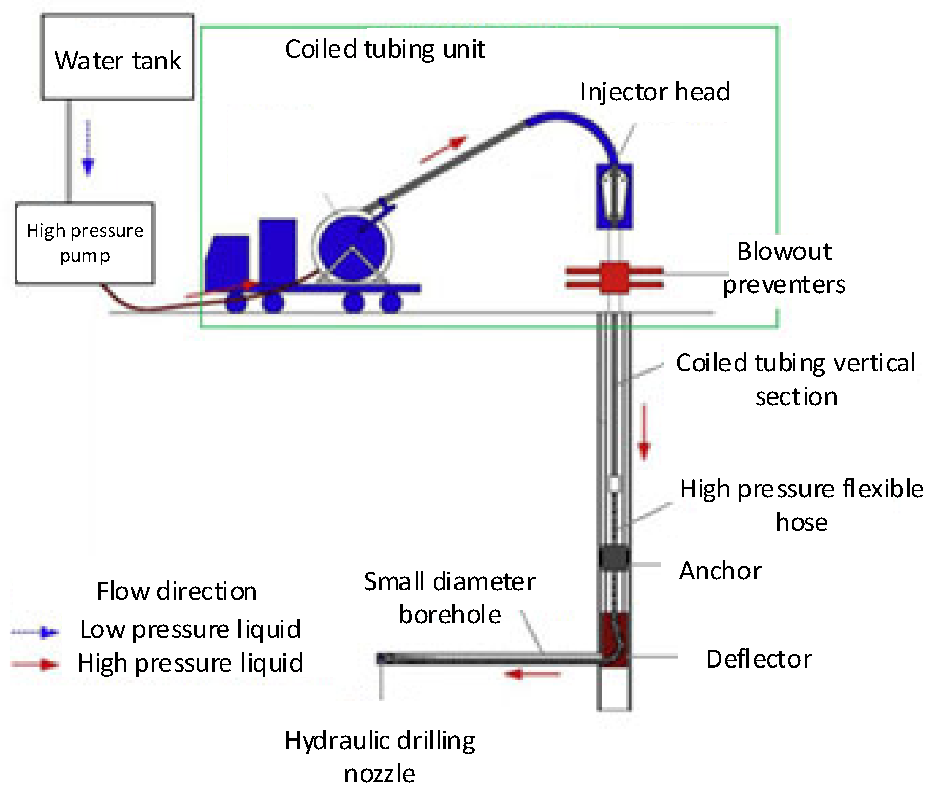
Currently, the jet nozzle drilling technology is widely employed for cutting, hydraulic jet drilling, or pipeline cleaning due to its capability to concentrate energy effectively in the jet [29]. The general equipment and tool scheme for creating radial holes using a high-energy liquid jet flowing through a nozzle at high pressure is depicted in Figure 5. This solution is commonly encountered in various forms and is extensively documented in numerous publications and some patents [4,8,9,11,21,30,31,32]. While individual solutions may vary in technical details, the fundamental approach to drilling radial boreholes remains rooted in hydraulic jet drilling techniques.
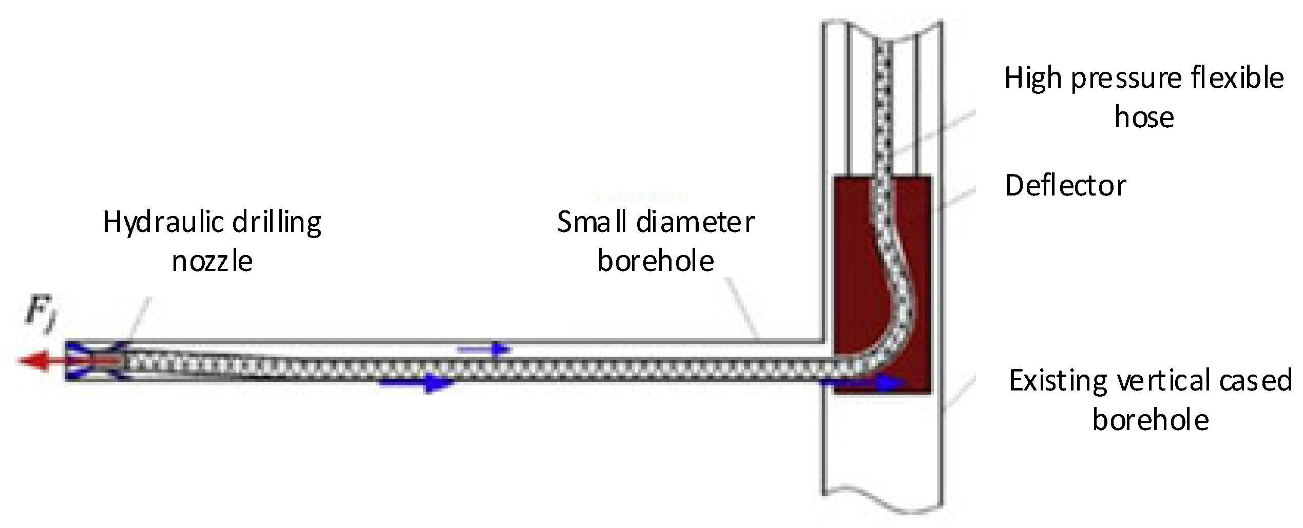
In the process of drilling such radial boreholes, the sections are typically horizontal, ranging in length from 100 to 300 m, with diameters falling between 40 and 60 mm. The considerable variation in the horizontal section lengths is attributed to specific requirements for the drainage zone length. The varying diameter of the radial boreholes is due to the nature of hydraulic radial drilling using a rotary nozzle, the structure of the wellbore medium, and various technological factors and parameters related to the reservoir rock. Figure 6 shows an enlarged diagram illustrating the nozzle going through the deflector.
Summers conducted fracture-cutting tests in six different types of rocks [33], employing 0.58 mm diameter jets operating at pressures as high as 172 MPa. The results showed that the depth of the fracture in these rocks experienced a decrease ranging from 60% to 80% when the penetration rate was increased within the range from 4.6 to 152 m/min, as illustrated in Figure 7.
Labus [34] conducted a series of fracture-cutting tests involving a 0.5 mm diameter water jet moved across Indiana limestone at ROP ranging from 10.1 to 40.64 cm/s, as presented in Table 2 and Table 3. These tests were executed at pressures as high as 1100 MPa. The data obtained from these experiments revealed that both the cracks-cutting specific energy and the specific energy decreased as the jet pressure decreased. This observation suggests that jets exhibit greater efficiency at lower pressures [34,35,36].
Additionally, when the ROP was increased from 10 to 40 cm/s, the cracks became narrower (0.2 cm versus 0.31 cm) and slightly shallower. These findings underscore the influence of jet pressure and ROP on the efficiency and dimensions of the cracks formed during the fracture-cutting process.
An increased rate of penetration has a significant effect on reducing the specific energy of fracture cutting, particularly at higher pressures [26,30,36]. For example, at pressures ranging from 1000 to 1100 MPa, the specific energy (specific drilling energy) of slot cutting decreased from 7240 to 1660 J/cm2 when the ROP was increased from 10 to 40 cm/s. This represents a substantial 77% reduction in power requirements for the slot-cutting tool in this rock. Similarly, at pressures of 200–300 MPa, the specific energy of the slot-cutting tool decreased from 1400 to 300 J/cm2, resulting in a 79% reduction in power demand.
Under specific operating conditions (rock type, nozzle size, pressure drop), there exists an optimal tool rate of penetration that minimizes the specific energy of fracture cutting. This optimal rate corresponds to the speed at which the exposure factor of the fracture surface (ROP × fracture depth) is maximized. Figure 8 illustrates that at 4896 bar, the slot-cutting operation with a 0.5 mm diameter jet was optimized at the ROP of 40 cm/s. At 7655 bar, the optimum velocity exceeded 50 cm/s, as evident from the continuing increase in the curve at this rate of penetration. Labus observed that interference between the jet and the walls of the drilled borehole decreased the efficiency of hydraulic jet drilling.

6. Conclusions

To identify directions for searching for an original solution, the authors observed that the fundamental components of a radial borehole drilling system typically involve nozzles crafted from robust materials such as hard stainless steel, tungsten carbide, or ceramic. These nozzles feature an outlet hole or holes located in the head or face tool of the rotary drilling nozzle, with the direction coinciding with the axis of the nozzle body or inclined in the plane of the axis. The nozzle itself can rotate relative to the axis of the nozzle head body, and the flexible hose coupling provides control over the direction of radial borehole propagation.
To explore an original solution, it is crucial to consider various factors and components that directly and indirectly influence the quality of continuous hydraulic jet drilling. Based on the observations above, the following conclusions were drawn:
  • The jet exhibits high-velocity vortex motion in the bottom zone from the frontal outlet hole(s) of the nozzle. This motion allows for an erosive action, ensuring the contact of the jet with the rock surface.
  • Backward outlet holes either allow for or assist the advance of the high-pressure flexible hose tool during hole propagation. Depending on their angle, they may also contribute to widening the excavated borehole.
  • The swirling stream of fluid from the reverse openings not only aids in the advance of the flexible hose but also facilitates the cuttings transport to the main wellbore.
  • The swirling motion of the outlet jet(s) can be optimized by changing the angle of the nozzle back holes, possibly spiraling through the housing wall and separating the front segment of the rotating nozzle.
  • The ROP (Fp) is determined by the equation Fp = Fs (jet force) − Fd (pressure force acting on the nozzle face) − Ft (frictional force of the nozzle drill head, flexible hose, friction and bending of the elastic hose in the deflector knee). This force is limited by the increasing length of the hose with the head in the horizontal borehole. Equilibrium is reached when the frictional forces are equal to the jet force in the nozzle, defining the maximum end length of the borehole.
  • The circumferential component forces of the vortex streams induce torsional moments from both the forward and the reverse vortex streams. Balancing these moments is critical to prevent excessive torsional stresses in the high-pressure flexible hose that could lead to buckling and vibration of the whole system. The angles and diameters of the front and rear nozzle outlets, as well as the potential bearing of the front of the rotating nozzle, affect the balance of these moments.
  • The introduction of an internal arrangement of inclined vanes, discs, or rotors to achieve a rotating fluid stream in the nozzle also affects the torsional stresses in both the flexible high-pressure hose and the nozzle, and this must be taken into account.
  • Optimal distance between the backward outlets and the facetool of the nozzle is crucial to maintain pressure balance in the rotary drilling nozzle.
  • When introducing a new solution that combines elements from known solutions, new functions or improvements to existing activities/functions should be meticulously identified. In addition, consideration should be given to reducing or enhancing the disadvantages associated with the new solution.
These considerations highlight the complexity of hydraulic jet drilling systems and the need for a careful design to optimize the performance and ensure stability during hydraulic radial drilling.
In the design solutions for equipment dedicated to hydraulic radial drilling of small-diameter boreholes, drilling nozzles stand out as a key area of interest. These nozzles can be simplified into a system comprising several components of the drill head (sometimes referred to under modified names) and the functions inherent to the designed system.
These functions include:
  • Hydraulic pressure: 70 MPa.
  • Jet speed: 300 m/s.
  • Distance of the nozzle outlet holes from the excavated rock sample.
  • Efficiency of adding an abrasive mass.
  • Type of abrasive material.
  • Shape of the abrasive grains.
  • Size and hardness of the abrasive materials.
  • Length and diameter of the nozzle.
  • Diameter of the nozzle outlet hole.
  • Rate of penetration, calculated as the difference between the force of the streams directed toward the back of the nozzle and that of liquid streams flowing out of the face of the nozzle.
Each of these parameters plays a crucial role in the effectiveness and efficiency of the hydraulic radial drilling process, particularly in the context of small-diameter hole applications such as drainage. The optimization of these factors contributes to the overall performance and success of the hydraulic radial drilling equipment.

Author Contributions

Conceptualization, P.T. and R.W.; methodology, P.T. and R.W.; software, P.T.; validation, R.W. and P.T.; investigation, and P.T.; resources, P.T.; data curation P.T.; writing—original draft preparation, P.T.; writing—review and editing, P.T.; visualization, P.T.; supervision, R.W. All authors have read and agreed to the published version of the manuscript.

Funding

This research received no external funding. The APC was funding from the subvention of the Department of Drilling and Geoengineering [16.16.190.779].

Conflicts of Interest

The authors declare no conflict of interest.

References

  1. Cinelli, S.D.; Kamel, A.H. Novel Technique to Drill Horizontal Laterals Revitalizes Aging Field. In Proceedings of the SPE/IADC Drilling Conference, Amsterdam, The Netherlands, 5–7 March 2013. [Google Scholar] [CrossRef]
  2. Jeffryes, B.P. Schlumberger Oilfield Research, Novel Drilling Techniques, Chapter 9.5. In Advanced Drilling and Well Technology; SPE: Willis, TX, USA, 2009. [Google Scholar]
  3. Dickinson Ben, W.O.; Dickinson, R.W. Horizontal Radial Drilling System. In Proceedings of the SPE California Regional Meeting, Bakersfield, CA, USA, 27–29 March 1985. [Google Scholar] [CrossRef]
  4. Toma, P.; Reitman, V.; Coffin, P.; Dickinson, W. Long and Ultrashort Turning Radius of Horizontal Wells Predictions of Future Production Based on Today’s Experience. In Proceedings of the 13th World Petroleum Congress, Buenos Aires, Argentina, 20–25 October 1991. [Google Scholar]
  5. Dongjun, M.A.; Li, G.; Huang, Z.; Niu, J.; Hou, C.; Liu, M.; Li, J. A Model of Calculating the Circulating Pressure Loss in Coiled Tubing Ultrashort Radius Radial Drilling. Pet. Explor. Dev. 2012, 39, 528–533. [Google Scholar] [CrossRef]
  6. Yonghe, L.; Chunjie, W.; Lianhai, S.; Weiyi, G. Application and Development of Drilling and Completion of the Ultrashort-radius Radial Well by High Pressure Jet Flow Techniques. In Proceedings of the SPE International Oil and Gas Conference and Exhibition in China, Beijing, China, 7–10 November 2000. [Google Scholar]
  7. Yan, C.; Ren, X.; Cheng, Y.; Deng, F.; Zhang, J.; Li, Q. An Experimental Study on the Hydraulic Fracturing of Radial Horizontal Wells. Geomech. Eng. 2019, 17, 535–541. [Google Scholar] [CrossRef]
  8. Dickinson Ben, W.O.; Anderson, R.R.; Dickinson, R.W. The Ultrashort-Radius Radial System. SPE Drill. Eng. 1989, 4, 247–254. [Google Scholar] [CrossRef]
  9. Salem Ragab, A.M. Improving well Productivity in an Egyptian Oil Feld Using Radial Drilling Technique. J. Pet. Gas Eng. 2013, 4, 103–117. [Google Scholar] [CrossRef]
  10. Abdel-Ghany, M.A.; Siso, S.; Hassan, M.A.; Pastura, P.; Cherri, R. New Technology Application, Radial Drilling Petrobel, First Well In Egypt. In Proceedings of the 10th Offshore Mediterranean Conference and Exhibition, Ravenna, Italy, 23–25 March 2011. [Google Scholar]
  11. Kamel, A.H. A Cost Effective Frackless Solution for Production Enhancement in Marginal Fields. In Proceedings of the SPE Eastern Regional Meeting, Canton, OH, USA, 13–15 September 2016. [Google Scholar] [CrossRef]
  12. Huang, Z.; Huang, Z.; Wu, L.; Su, Y.; Hong, C. Trajectory Measurement of Radial Jet Drilling Wells: Improved Tool and Data Processing. J. Energy Resour. Technol. 2020, 142, 032902. [Google Scholar] [CrossRef]
  13. Dickinson Ben, W.O.; Dykstra, H.; Nees, J.M.; Dickinson, E. The Ultrashort Radius Radial System Applied to Thermal Recovery of Heavy Oil. In Proceedings of the SPE Western Regional Meeting, Bakersfield, CA, USA, 30 March–1 April 1992. [Google Scholar] [CrossRef]
  14. Retalic, I.; Laird, A.; MacLeod, A.; Senergy, L.E.A. Coiled-Tubing Drilling, Chapter 9.4. In Advanced Drilling and Well Technology; SPE: Willis, TX, USA, 2009. [Google Scholar]
  15. Wiśniowski, R. Wybrane Aspekty Projektowania Konstrukcji Otworów Kierunkowych z Wykorzystaniem Technik Numerycznych; Uczelnianie Wydawnictwa Naukowo Dydaktyczne AGH: Kraków, Poland, 2002. [Google Scholar]
  16. Wiśniowski, R.; Stryczek, S. Wybrane Aspekty Projektowania Trajektorii Osi Otworów Kierunkowych Wierconych z Podziemnych Wyrobisk Górniczych, Zeszyty Naukowe Politechniki Śląskiej, Seria Górnictwo z.279, Nr kol. 1764, Gliwice. 2007. Available online: https://delibra.bg.polsl.pl/Content/74362/BCPS-83468_2007_Wybrane-aspekty-proj.pdf (accessed on 8 January 2024).
  17. Wiśniowski, R.; Teper, W.; Zwierzyński, A.J.; Złotkowski, A.; Toczek, P. Sposób Powierzchniowego Odmetanowania Formacji Geologicznej Zawierającej Złoże Węgla Kamiennego, Akademia Górniczo—Hutnicza w Krakowie, Opis zgłoszeniowy wynalazku PL 436375 A1, Opubl. 2022-06-20, Zgłosz. nr P.436375 z dn. 2020-12-17, Biuletyn Urzędu Patentowego, ISSN 0137-8015, nr 25, s. 15, Kraków. 2022. Available online: http://patenty.bg.agh.edu.pl/pelneteksty/PL436375A1.pdf (accessed on 8 January 2024).
  18. Maurer, W.C. Advanced Drilling Techniques; Petroleum Publishing Co.: Tulsa, OK, USA, 1980. [Google Scholar]
  19. Wiśniowski, R.; Knez, D.; Hytroś, Ł. Drillability and Mechanical Specific Energy Analysis on the Example of Drilling in The Pomeranian Basin. AGH Drill. Oil Gas 2015, 32, 201–209. [Google Scholar] [CrossRef]
  20. Toczek, P.; Wisniowski, R.; Stryczek, S.; Ziaja, J.; Mazur, C. Total Specific Energy (TSE) as a New Indicator of Drilling Efficiency. AGH Drill. Oil Gas 2017, 34, 715–729. Available online: https://journals.bg.agh.edu.pl/DRILLING/2017.34.3/drill.2017.34.3.715.pdf (accessed on 8 January 2024).
  21. Kamel, A.H. Radial Jet Drilling: A Technical Review. In Proceedings of the SPE Middle East Oil & Gas Show and Conference, Manama, Bahrain, 6–9 March 2017. [Google Scholar] [CrossRef]
  22. Gang, B.; Gensheng, L.; Zhonghou, S.; Huang, Z.; Dongjun, M.; Liangbin, D. Experimental Research on the Technology of Hydra-Jet Sidetracking of Radial Micro-borehole. J. Eng. Sci. Technol. Rev. 2013, 6, 137–142. [Google Scholar] [CrossRef]
  23. Conn, A.F.; Rudy, S.L. Parameters for a Ship Hull Cleaning System Using the Cavitating Water Jet Method; National Technical Information Service, TR-7510-1 Final Rpt.; Maritime Administration: Washington, DC, USA, 1975.
  24. Johnson, V.E. Process for Drilling by a Cavitating Fluid Jet. U.S. Patent 3528704, 15 September 1970. [Google Scholar]
  25. Conn, A.F.; Rudy, S.L. Cutting Coal with The Cavijet Cavitating Water Jet Method. In Proceedings of the 3rd International Symposium Jet Cutting Technology, Chicago, IL, USA, 11–13 May 1976. [Google Scholar]
  26. Conn, A.F.; Radtke, R.P. CAVIJET Augmented Deep-Hole Drilling Bits. J. Pressure Vessel Technol. 1978, 100, 52–59. [Google Scholar] [CrossRef]
  27. Lichtarowicz, A. Experiments with Cavitating Jets. In Proceedings of the 2nd International Symposium on Jet Cutting Technology; British Hydromechanics Research Association: Cambridge, UK, 1974. [Google Scholar]
  28. Minghui, W.; Chenghuai, W.; Yanxi, Z. Numerical Simulation and Experimental Study on Flow of Polymer Aqueos Solution in Porous Jet Nozzle. Adv. Polym. Technol. 2020, 2020, 7580460. [Google Scholar] [CrossRef]
  29. Landers, C. Method of and Apparatus for Horizontal Drilling. U.S. Patent 6125949A, 3 October 2000. [Google Scholar]
  30. McLeod, R.D.; Dwight, N.L. Lateral Jet Drilling System. U.S. Patent 6189629B1, 20 February 2001. [Google Scholar]
  31. Peters, J.N. Method and Apparatus for Lateral Well Drilling Utilizing an Abrasive Fluid Stream Discharged from Rotating Nozzle. U.S. Patent 0173544A1, 9 July 2009. [Google Scholar]
  32. Chi, H.; Li, G.; Huang, Z.; Tian, S.; Song, X. Maximum Drillable Length of the Radial Horizontal Micro—Hole Drilled with Multiple High-Pressure Water Jets. J. Nat. Gas Sci. Eng. 2013, 26, 1042–1049. [Google Scholar] [CrossRef]
  33. Summers, D.A. Water Jet Cutting Related to Jet and Rock Properties. In Proceedings of the 14th U.S. Symposium on Rock Mechanics (USRMS), University Park, PA, USA, 11–14 June 1972. [Google Scholar]
  34. Labus, T.J. Energy Requirements of Rock Penetration by Water Jets. In Proceedings of the 3rd International Symposium on Jet Cutting Technology, Paper No. E3, Chicago, IL, USA, 11–13 May 1976. [Google Scholar]
  35. Labus, T.J. Cutting and Drilling of Composites Using High Pressure Water Jets. In Proceedings of the Fourth International Symposium on Jet Cutting Technology, Canterbury, UK, 12–14 April 1978. [Google Scholar]
  36. Labus, T.J. High-Pressure Water Jet Applications in Drilling Operations, In High-Pressure Science and Technology; Timmerhaus, K.D., Barber, M.S., Eds.; Springer: Boston, Ma, USA, 1979. [Google Scholar] [CrossRef]
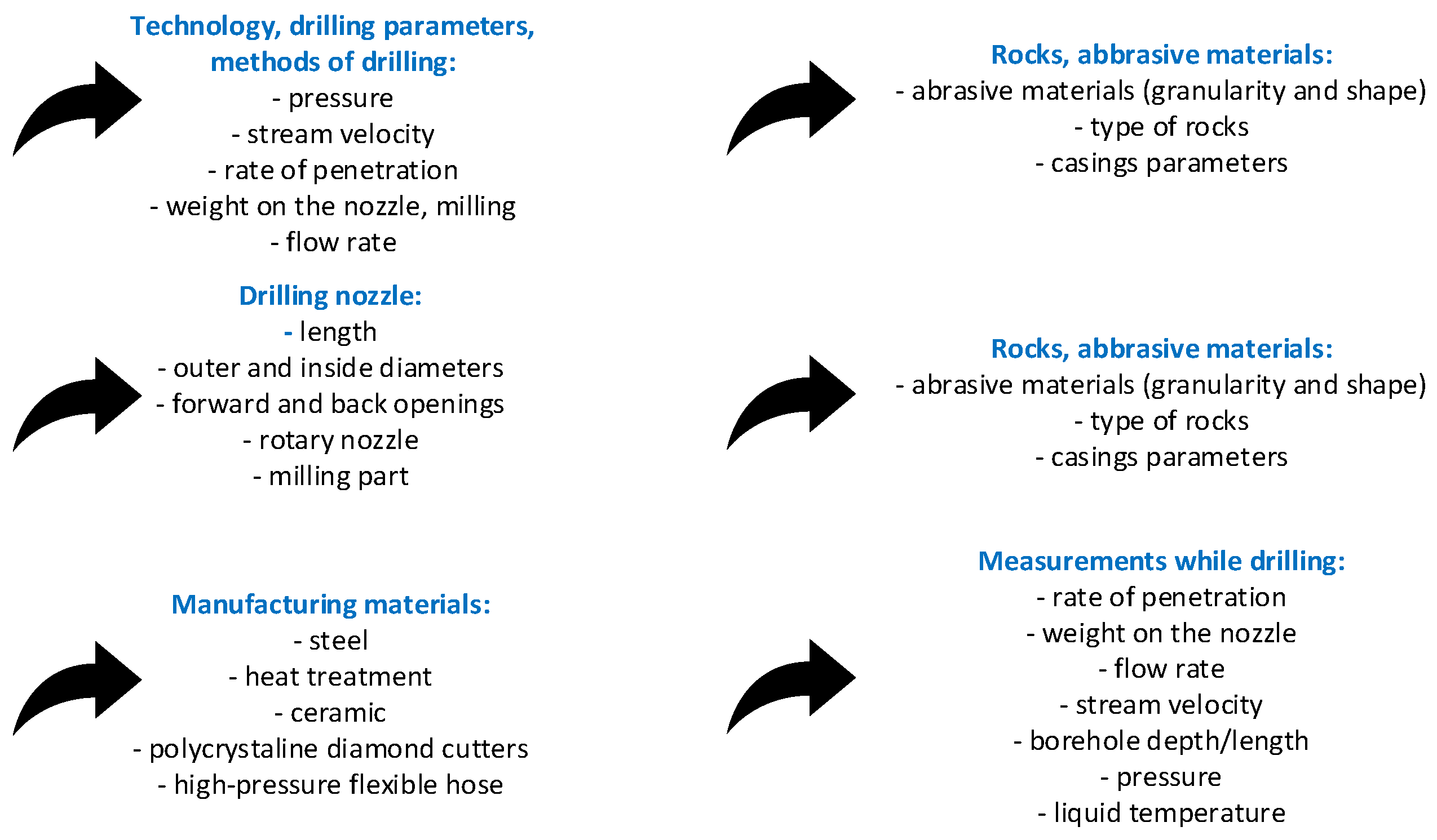
Figure 1. The main components of a drilling nozzle taken into account during the literature review.
Applsci 14 03552 g001
Figure 2. Cavitation build-up pressure [23].
Applsci 14 03552 g002
Figure 3. Data for coal hydraulic drilling test using a cavitation jet.
Applsci 14 03552 g003
Figure 4. (a) The effect of the distance of the nozzle from the surface to be worked on the eroding process by a cavitation jet, (b) the rate of cavitation erosion.
Applsci 14 03552 g004
Figure 5. Scheme of drilling radial boreholes with an ultrashort angle of curvature [33].
Applsci 14 03552 g005
Figure 6. Equipment of borehole hydraulic jest drilling techniques [33].
Applsci 14 03552 g006
Figure 7. Results for jet fracture cutting in various rocks [33].
Applsci 14 03552 g007
Figure 8. Drilling velocity extremes for different jet pressures depending on the exposure factor for Indiana sandstone.
Applsci 14 03552 g008
Table 2. Influence of the jet pressure value on the specific energy of slot cutting at a rate of penetration v = 10.1 cm/s for Indiana limestone [34].
Stream Pressure,
MPa
Jetting
Velocity,
m/s
Average Crack Depth,
cm
Average Crack Width,
cm
Stream Power,
kW
Specific Energy of Jet Drilling,
J/cm3
Specific Energy of Jet Drilling per Unit of Crack Volume,
J/cm2
1000–110010.14.200.3130766307240
900–100010.14.120.3125955706220
800–90010.14.600.3123044204950
700–80010.13.750.3119052405020
600–70010.13.640.3113860403750
500–60010.13.910.3111771002960
400–50010.13.300.317649102280
300–40010.13.320.315652201670
200–30010.12.680.313827601400
100–20010.11.670.31142620830
0–10010.11.110.3151490445
Table 3. Influence of the jet pressure value on the specific energy of slot cutting at a rate of penetration v = 40.64 cm/s for Indiana limestone [34].
Stream
Pressure,
MPa
Jetting Velocity,
m/s
Average Crack Depth,
cm
Average Crack Width,
cm
Stream Power,
kW
Specific Energy of Jet Drilling,
J/cm3
Specific Energy of Jet Drilling per Unit of Crack Volume,
J/cm2
1000–110040.644.280.2028951601660
900–1000No data available
800–90040.644.760.2022340001150
700–80040.643.330.2016437401210
600–70040.643.600.201403470960
500–60040.642.960.201063960880
400–50040.642.750.20833750740
300–40040.642.970.20571900470
200–30040.642.690.20331370300
100–200No data available
0–100No data available
Disclaimer/Publisher’s Note: The statements, opinions and data contained in all publications are solely those of the individual author(s) and contributor(s) and not of MDPI and/or the editor(s). MDPI and/or the editor(s) disclaim responsibility for any injury to people or property resulting from any ideas, methods, instructions or products referred to in the content.