

Steel Arch and Rock Bolt Support in Terms of the Gateroad Stability Maintaining behind the Longwall Face

1
Faculty of Civil Engineering and Resource Management, AGH University of Krakow, al. A. Mickiewicza 30, 30-059 Krakow, Poland
2
Faculty of Mechanical Engineering and Robotics, AGH University of Krakow, al. A. Mickiewicza 30, 30-059 Krakow, Poland
*
Author to whom correspondence should be addressed.
Appl. Sci. 2024, 14(9), 3594; https://doi.org/10.3390/app14093594
Submission received: 10 March 2024
/
Revised: 17 April 2024
/
Accepted: 22 April 2024
/
Published: 24 April 2024
(This article belongs to the Special Issue Advanced Research on Tunnel Slope Stability and Land Subsidence)
Abstract
:The longwall system is an extraction system commonly used in coal mining in many countries, including Poland. One of the methods for reducing extraction costs is the dual use of the gateroad. In the first instance, the gateroad serves as the tailgate, and during the exploitation of the second coal panel, it functions as the headgate. Such a situation requires maintenance of the roadway behind the longwall face, which is typically challenging, due to significant stress-related loads on the support and its substantial deformation. The support design for this kind of roadway should take into consideration the dual impact of exploitation pressure and the caved zone influence behind the longwall face. This article presents the results of in-situ research conducted on two roadways behind the longwall face. In both roadways, the effectiveness of specially designed steel arch frames and rock bolt patterns were examined to minimize roadway deformations and maintain their functionality. The research project was comprised of several stages. Initially, mining and laboratory studies were conducted to determine the geomechanical parameters of the rocks. Subsequently, excavation stability and functionality forecasts were performed based on the authors’ empirical indicators. Then, numerical analyses were carried out to design support schemes (steel arches and rock bolt) in both roadways. A fully automated monitoring system with programmed data loggers was designed to check the behaviour of a specific rock mass and the support elements. The load on the steel arch support was measured with the help of load cells, while the load on the rock bolt support was carried out with the help of measurement bolts. Behind the longwall face, the loads on the wooden cribs set from the goaf side were also monitored. Additionally, the measurement station was equipped with extensometers to monitor the movement of roof layers and stress meters to determine changes in rock mass stress. Laser scanning or traditional surveying methods were also used to verify the support schemes through roadway convergence measurements. The obtained results allowed us to draw conclusions regarding the optimization of support schemes and to give recommendations for the practical application of specific reinforcements in excavations maintained behind the longwall face.
1. Introduction
Underground extraction of mineral resources requires the application of practical methods for maintaining roadways. In many countries worldwide, including Poland, coal mining is a significant sector for both the economy and energy security, and the efficiency of methods of resource extraction determine the competitiveness of production. One of the factors influencing cost reduction is the technology for maintaining gateroads, which helps to ensure an appropriate cross-sectional area for ventilation, transport and haulage purposes, and thereby establish a safe working environment for the staff. Maintaining the stability of these roadways behind the longwall face requires the application of suitable support schemes that consider specific geological and mining conditions. In the context of international experiences, these technologies are relatively uncommon, which does not mean that the maintaining of roadways behind the longwall face is not used at all. One example is coal mines in China, where such solutions are increasingly encountered [1,2] and another example is Poland [3].
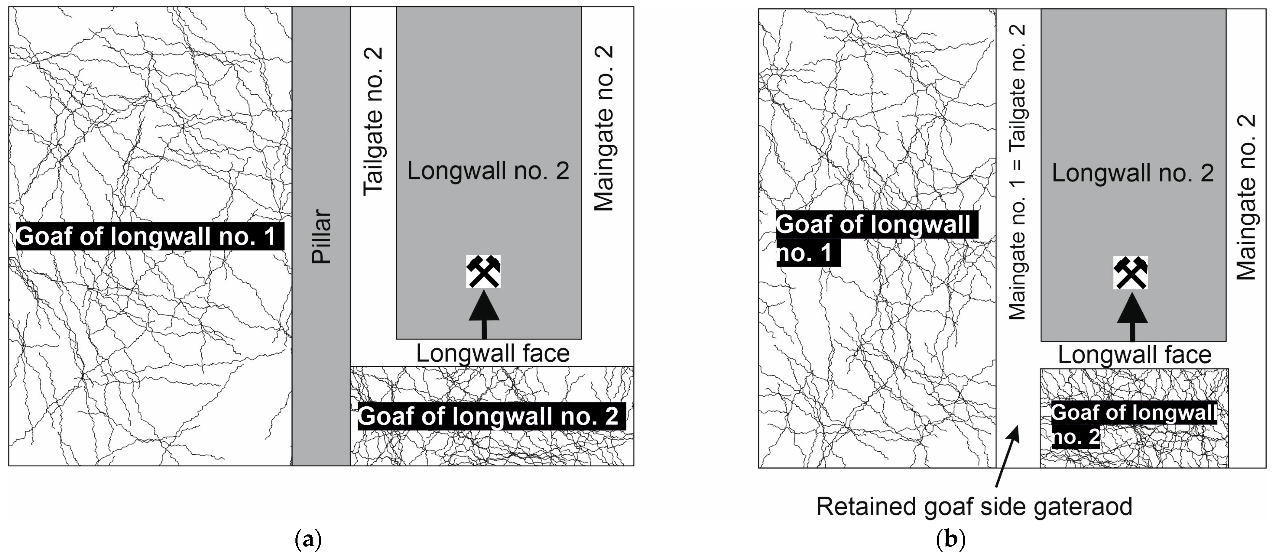
Maintaining roadways behind the longwall face in coal mines is mainly associated with ventilation requirements in high methane-risk environments, but it also aims to preserve transportation routes or facilitate reuse for adjacent longwalls [3,4,5] (Figure 1). There are even known cases where roadways are maintained in the mutually surrounding environment of goaf [6]. Protecting the roadway behind the longwall face is a challenging task. Mines have been seeking new technologies in this area for years or refining currently applied methods. Recent years have shown that two methods are commonly used for maintaining workings next to a longwall panel. In the first method, which is widely used in Australia and was used in England, the damage zone is moved from the new driven gate, leaving a pillar between the tailgate and new maingate (Figure 1a). To obtain an intact rock above the maingate, the pillar should be very wide, and especially have a great depth. But leaving a 4 ÷ 5 m pillar allows a new gate to be driven in the destressed zone, which is the practise in Poland. In the second method the same gateroad is used twice, so next to collapsing roof rocks next to a goaf [7]. Using this method, the former maingate for the second panel serves as a tailgate. To ensure stability in a maintained roadway, wooden or friction props are commonly used behind the longwall face, as well as steel hoisting joists and wooden cribs filled with aggregate or bags filled with binding material [8]. The line of cribs or concrete columns built along goaves is commonly referred to as “artificial protective pillar” [9].
The methods for maintaining roadways behind the longwall face are also based on experiences of working in various mines [10]. Therefore, maintaining roadways behind the longwall face is carried out based on an individual design relying on empirical relationships to estimate the load acting on the roadway support.
The most crucial aspect of the technology of maintaining roadways behind the longwall face is the design of appropriate support, taking into account reinforcements at different stages of the existence of the roadway. The applied support elements should ensure the stability of a roadway against stress concentration caused by advancing longwall face and the influence of goaf. Maintaining the gateroad behind the longwall face in an independent rockbolting support requires additional reinforcement with hydraulic props and a protective pillar of flexible concrete on the goaf side [11]. The rockbolting support scheme requires proper design, which has to take into consideration the entire lifecycle of the roadway [12,13,14,15]. Years of experience in Polish coal mines show that it is challenging to identify a universal support scheme. This is due to the considerable depth, usually 800 ÷ 1300 m, as well as the complex system of tectonic disturbances and the occurrence of numerous mining edges of higher mined coal seams. However, various steel arch and rock bolt support variants are vital in designing roadways. Modifying the steel arch and rock bolt support usually considers the spacing of steel frames, the load-bearing capacity of support elements and the contact between the rock mass and frames. In the case of rock bolts, modifications include the type, length, distribution, and method of rock bolt installation.
The maintenance of roadway stability behind the longwall face over the designated period is a subject that has undergone numerous numerical analyses [16,17], as well as field studies and physical modelling [18,19]. In international references, one can find measurement results of stress changes, considering the advancing longwall face [20], movements of the rock mass [21] or roadway convergence, both ahead and behind the longwall face [22]. However, comprehensive monitoring of the gateroad in natural conditions, encompassing observations of the rock mass and the performance of the steel arch and rock bolt support, has not yet been encountered in the relevant literature.
This article presents a comprehensive approach to designing and monitoring roadways maintained behind the longwall face. Initially, geomechanical studies were conducted, which were then used to develop numerical models and forecast the stability of excavations, based on empirical indicators developed by authors. The use of empirical indices allowed for the selection of appropriate support and its reinforcement and the assessment of challenges in maintaining roadways behind the longwall face. The numerical analysis aimed to estimate the extent of the fracture zone around the tested roadways, both ahead and behind the longwall face. These results were utilized to design the final support schemes. Subsequently, fully automated monitoring stations were designed in tested roadways, monitoring the steel arch, rock bolt support, and surrounding rock mass around the roadway, ahead and behind the longwall face. The test area comprised two main gates in two Polish hard coal mines. Both contained three sections of a specially designed support scheme. The originality of the project is worth noting, as publications describing measurement results from different support schemes operating under the same conditions are rare. The monitoring system was the first to be applied in Polish coal mines.
2. The Project of Roadways Maintained behind the Longwall Face
The most commonly used method for designing support systems for roadways relies on selecting support that can withstand the load of the fracture zone formed in the surrounding rock mass as a result of roadway excavation (Figure 2). To determine the size and shape of the fracture zone, well-established theories (for example Protodiakonov, Salustowicz, Cymbariewicz) are applied, utilizing the dimensions of excavations and the geomechanical parameters of the rock mass (σc, σt, E, ν, c, ϕ). However, it should be noted that these theories do not take into account situations where the roadway is maintained behind the longwall face. If it is necessary to use the roadway within the goaf, the design of its support system is typically based on practical experience from the mine. In this case, the support selection was based on the results of the numerical analysis. The use of specialized computer software Flac 7.0 employing the Finite Difference Method (FDM) allowed us to estimate the damage zone around the chosen roadways, both ahead and behind the longwall face, thereby considering the influence of the one-sided interaction of the goaf.
2.1. Identification of Mining and Geological Conditions
Two roadways located in two different coal mines, “Budryk” and “Pniowek”, were selected for tests in the southern part of the Upper Silesian Coal Basin in Poland. The roadways were named Bw-4 and PW-1 and served as maingates. In both roadways, the first boreholes were drilled to determine the geomechanical parameters. Penetrometer tests were conducted on each of these boreholes, and a series of laboratory tests on samples obtained from the drill cores were then performed. The results are summarized in Table 1. The thickness of the coal seam in both maingates was 2.5 m and 1.9 m, respectively. There was shale in the roof and on the floor of the coal seam and in the roof and on the floor of both roadways. Mudstone beds or sandstones were found at a distance of 2.5 ÷ 4.8 m from the roof
2.2. Numerical Models
The numerical model was a rectangular shield with dimensions of 100 m × 80 m in a plane strain. A Coulomb–Mohr elastic–plastic model was adopted for all layers. The model was built according to the geological profile, with rock bed properties shown in Table 1. Structural beam elements of the “liner” type were used to model the support system. A contact plane was assumed between the support elements and the rock mass, with parameters corresponding to the mechanical (cement bond) lining parameters. Structural “cable” elements were used to model the rock bolt support system, with load capacities according to technical specifications.
The Finite Difference Method (FDM) was applied to the calculations, and discretization was performed using FLAC 7.0 software. The computational grid was densified around the excavation to approximately 25 cm × 20 cm. Stress states were analysed, ahead and behind the longwall face, and the results were presented as maps, illustrating the distribution of vertical stresses in the rock mass and the range of plastic zones.
The analysis revealed that in Bw-4, the maximum values of vertical compressive stresses ahead of the longwall face occur in the coal sidewalls and reach a value of 45 MPa (Figure 3a). Additionally, areas of tensile stresses can be observed, particularly in the floor. The destressed zone in the roof extends to approximately 2 m and to approximately 3.5 m in the floor, but complete rock damage does not occur here. Figure 3b illustrates the extent of plastic zones (cracks) around Bw-4. Particular attention should be paid to indicators of plastic changes (interpreted here as cracking). Shear and volumetric changes are shown in red, while damage due to tension is in purple. High tensions occur only in the roadway’s floor. The fracture range includes the seam and the overlying clay shales up to 1.5 m above the sidewall.
For the next step, a goaf was modelled behind the longwall face, and separated from Bw-4 by a wooden crib, taking into account the stress state ahead of the longwall face. A wooden crib filled with aggregate with external dimensions of 1.2 × 1.2 m was designed at the sections of the steel arch support from the goaf side. It was assumed that the actual bearing capacity of this support would be no less than 8 MN.
The results of the calculations showed that maximum values of vertical compressive stresses occur in the coal sidewall behind the steel arch support and reach 42 MPa (Figure 4a), which is slightly lower than ahead of the longwall face. Stresses in the area of the wooden crib reach 48 MPa. The range of the plastic zone is significantly more comprehensive than ahead of the longwall face. This is because it extends up to 4 m above the sidewall and the wooden crib (Figure 4b). However, it should be noted that the rock bolt from the goaf side operates in unfractured rock mass.
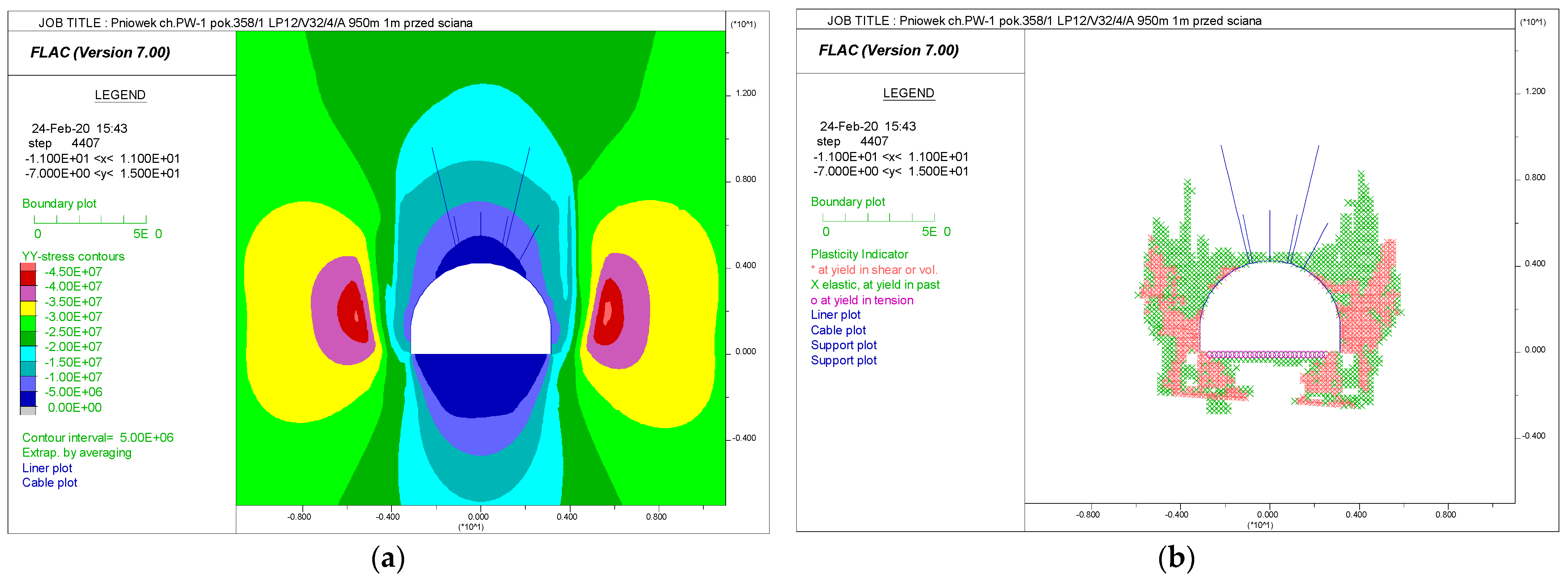
Numerical analysis of the PW-1 maingate stability showed that maximum values of vertical compressive stresses ahead of the longwall face occur in the coal sidewalls and reach 45 MPa (Figure 5a). The destressed zone in the roof extends to approximately 1.5 m and to approximately 3 m in the floor. Figure 4b illustrates the range of the plastic zone (cracks) around PW-1. According to the results, the range of fractures reached up to 5 m above the sidewall and approximately 2.7 m in the floor (Figure 5b). Therefore, the upper sections of the rock bolts operate in unfractured rock masses.
The PW-1 roadway model behind the longwall face was designed similarly to the Bw-4 roadway model. The maximum values of vertical compressive stresses occur again in the shale in the coal sidewall behind the support and reach 42 MPa (Figure 6a). Meanwhile, the stresses beneath the edge of the wooden crib reached 40 MPa. The range of the fracture zone behind the longwall face significantly increased, reaching a height of 7 m above the sidewall and the wooden crib (Figure 6b). In this kind of situation, two rock bolts operate in a fractured rock mass. The results caused a change of the rock bolts’ final arrangement in a rock mass.
3. Indices of Roadways Stability
The mining–geological conditions in gateroads are often diverse, significantly influencing rock mass stress and the designed support structure. Various indices are utilized to assess difficulties in maintaining the roadways. These indices consider various factors that characterize the rock mass and mining conditions [23,24,25].
One of them, which pertains to the roof lithology, is defined as the roof lithology index WL [26]. This index is calculated as the weighted average thickness of lithological layers overlying the roof of the designed excavation up to 10 m. The thickness of individual rock layers is multiplied by a reduction coefficient dependent on the rock type. The obtained result indicates which of the rock layers dominates in the roof of an excavation. Complementing this method is the crack rate n, determined as a ratio of the number of cracks to the number of rock layers over 10 m of an excavation roof. The parameters described above characterize the quality of the rock mass. So, the crack rate n provides information on discontinuities present in the roof, particularly their intensity and density. Considering a depth H at which the excavation is located relative to a critical depth Hkr, these indicators help to forecast a required reinforcement of the support structure to maintain excavation stability. Based on the above parameters, four variants of loading and deformation of the specific type of support structure in the subject excavation are distinguished (Table 2).
Determining the uniaxial compressive strength (UCS) of roof rocks and characterizing the fracture pattern under in situ conditions enabled the calculation of the crack rate n and the roof lithology index, WL (Table 3). These tests were conducted in two roadways: Bw-4 (at six locations) and PW-1 (at three locations), which were buried at a depth of 1050 m and 950 m, respectively. This significantly exceeded the critical depth. An IV-level forecast scenario was achieved based on the WL parameters. This indicates that to maintain the stability of the roadways, it is necessary to implement a steel arch support, made of high steel grade and hoisting joists (V-shape steel beams) bolted to the roof, with the help of high-bearing capacity cable strand bolts.
There is another method that evaluates the effectiveness of roadway support design for specific mining–geological conditions [27,28]. This two-stage assessment relates to the possibility of successfully designing a stable roadway. Firstly, the Roadway Design Efficiency index (RDE) is calculated, followed by the Roadway Functionality Maintenance index (RFM). The first one takes into account geological, geomechanical and mining factors, while the second one consider technical factors. This method, for given mining–geological conditions, indicates if the designed support can maintain the functionality of the roadway for the required period or not. A points-based classification was established based on the relationships used to determine these indicators (Table 3). The value of the Roadway Design Efficiency index (RDE) can reach 240 points and the Roadway Functionality Maintenance index (RFM) ranges from 5 to 100 points, and is divided into six classes, as shown in Table 4. The method was described in detail in [27].
Considering the technical conditions associated with the support’s characteristics, the RFM’s value was also determined (Table 5). The values of this index ranged from 48 to 53 points for PW-1, and from 56 to 60 points for Bw-4. Based on this, PW-1 achieved the IV class of effectiveness in maintaining the roadway, indicating difficulties in sustaining the roadway within the specified time. In contrast, Bw-4 was forecasted to have fewer difficulties maintaining the roadway obtaining Class III.
Another helpful indicator for predicting the stability of the roadway is the ERMF—Endoscopic Rock Mass Factor [29,30]. This index reflects the actual roof conditions. It is based on endoscopic tests in roof boreholes with the help of a camera. The observation of roof rock cracking allows the rock’s mass quality to be assessed. Three parameters determine the value of the ERMF factor: the number of cracks (ls), total separation (rr) and the range of intensive cracks (zis). Longer sections of fractured rock and large number of separations can reduce the quality. Six classes were designed according to the above parameters and the details are presented in Table 6. Among the listed parameters is the range of intensive cracks, which is crucial for the final result. The assessment provides a recommendation for the reinforcements of the support that are necessary to ensure the stability of a roadway. The general assumption is that the basic support in a roadway is a steel yielding support.
High-intensity crack zones were observed in the roof of Bw-4. The total separation largely determined the class, and hence the rock mass class was classified as I, II, or III (Table 6). Due to the various roof conditions in Bw-4, bolting between steel arches was recommended to ensure stability.
A significantly weaker rock mass class was determined for PW-1. Excavating the roadway directly under the seam edge, about 20 m above, resulted in a very extensive crack zone, reaching a height of over 10 m above the roadway. Intensive cracks were also observed up to 2 ÷ 3 m above the roof contour. The rock mass was severely damaged at the first two research stations, as the cumulative total separation reached almost 100 cm, with nearly 100 registered discontinuities. For all the tested stations, a rock mass of class V was determined. In this roadway type, which is classified as “weak” according to the ERMF classification, the steel arch support should be reinforced with two rows of hoisting joists fixed to the roof with the help of long cable strand bolts, preferably with pre-tensioning and Bullflex bags (Table 7).
4. Test Area in the Bw-4 and PW-1 Roadways
Based on the results obtained from the numerical analysis and stability indicators, three test sections were designed in both roadways, with various support schemes applied. The support scheme for the first test section was, in both roadways, designed according to practical mine experience in maintaining the roadways behind the longwall face. The following two test sections were designed utilizing new support elements—Titan cable strand bolts with pre-tensioning (Figure 7a)–and the ŁPi steel arch support with a groove in the roof arch, which blocked the lower yoke and guided the frame arch sliding under their loading (Figure 7b).
Bw-4 had to be maintained, for ventilation reasons, behind the longwall face. The designed reinforcements were intended to ensure a required cross-section for the roadway during abutment pressures, and then goaf influence along the coal sidewall. The support schemes in Bw-4 for each test section consisted of a ŁP11/V32/4 steel yielding arch support (on test section III, the modified ŁPi11/V32/4 type support with a groove was applied, L = 2.83 m—Figure 7b). The width of the roadway was 5.8 m, with a height of 4.025 m, and the frame spacing was 1 m. Additionally, the specific reinforcements on individual sections were as follows:
- Test section I—two rows of hoisting joists V32-type (32 kg/m) fixed to the roof (every 1 m) by IR-6 cable strand bolts with a total length of 9 m; 3 Bullflex bags with a length of 1.5 m filled with cementitious material (Figure 8a);
- Test section II—two rows of hoisting joists V32-type with a length of 1.4 m fixed to the roof (every 2 m) by IR-5 injection cable strand bolts with a total length of 7 m; three steel rock bolts with a length of 2.5 m in each span between the arches; and a total of 3 Bullflex bags (Figure 8b);
- Test section III—two rows of hoisting joists V32-type with a length of 1.4 m fixed to the roof (every 2 m) by IR-5 injection cable strand bolts with a total length of 7 m; a total of three steel rock bolts with a length of 2.5 m in each span between the arches, with the outermost ones built every second span, depending on the presence of a cable strand bolt in the row; additional hoisting joist from the longwall side; rock lining (Figure 8c).
A characteristic feature of the ŁPi11/V32/4-type support applied in test section III is the modified method of the construction of the take-up device on the roof arch while maintaining the geometry of the ŁP11-type support. During testing, it was observed that arches with this design exhibit uniform sliding on the clamps throughout the entire range of operation on the yielding characteristic.
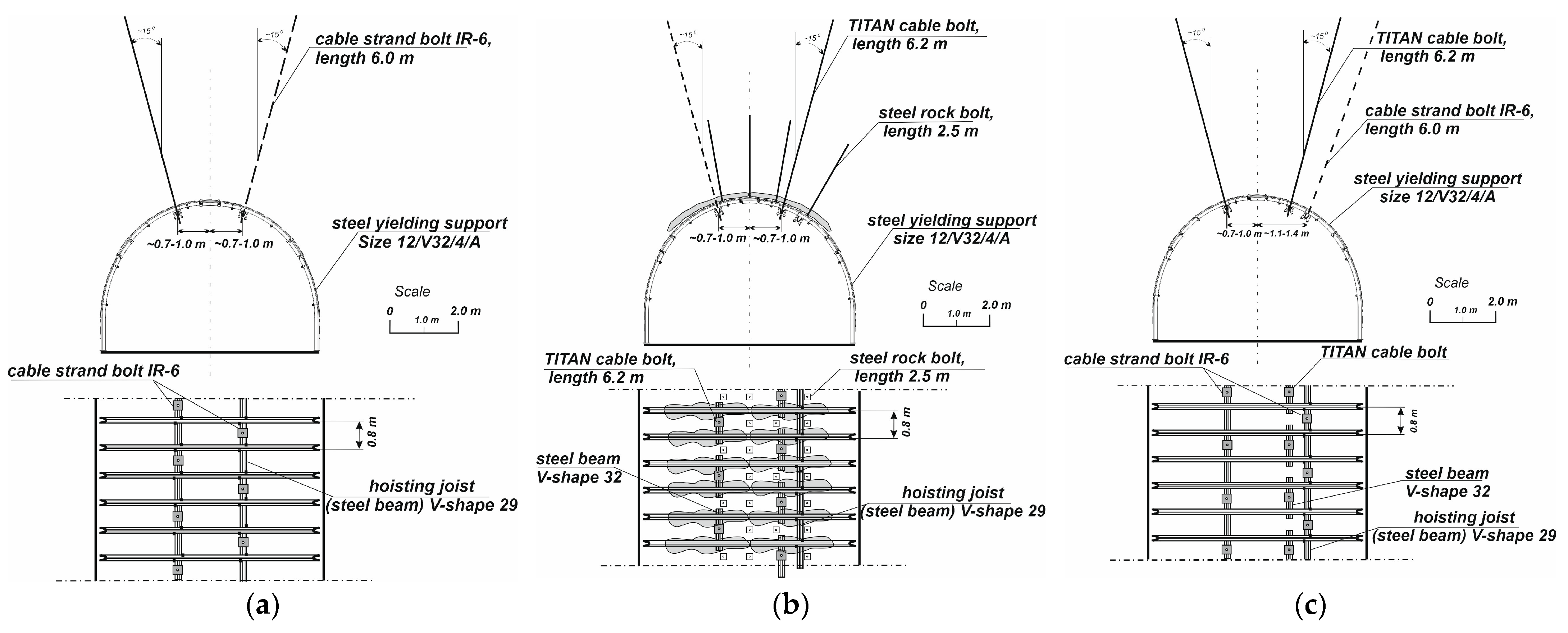
In PW-1, different support schemes were applied on three tested sections. In each case, the primary support consisted of ŁP12/V32/4/A-type steel yielding arch support with a width of 6.1 m and height of 4.225 m, which was built with a spacing of 0.8 m. The schemes for each section of the roadway were as follows:
- Test section I—two rows of V29-type (29 kg/m) hoisting joists fixed to the roof every second meter by IR-6 cable strand bolts with a total length of 6 m that were installed with the help of two resin cartridges; rock lining was used (Figure 9a);
- Test section II—V29-type hoisting joist from the goaf side directly fixed to the steel arch support; two rows of Titan cable bolts with a length of 6.2 m installed every second frame—additionally, the roof was bolted with three steel rock bolts with a length of 2.5 m, with the outermost bolts alternately used with Titan cable bolts with a length of 6.2 m; Bullflex bags were used on roof arches (Figure 9b);
- Test section III—two rows of V29-type hoisting joists fixed to the roof every second meter by IR-6 cable strand bolts with a total length of 6 m; 6.2 m Titan cable bolts were installed from the coal sidewall; rock lining was used (Figure 9c).
5. Monitoring Station
The automatic monitoring system applied in both roadways was the first of its kind in Polish coal mining, serving as a comprehensive stability control system for the roadway. The underlying assumption was that it would be able to automatically monitor rock movements and pressures on the support cyclically by data recording, and facilitating remote data retrieval.
The equipment for each measuring station consisted of (Figure 10):
- load cell sensor installed on the roof arch on specially profiled washers;
- MPBX-type extensometer with a length of 6 m and four measuring levels;
- rock bolt stressmeter with a length of 6 m and six measuring levels;
- load cell sensor installed on the wooden crib;
- two biaxial stressmeters installed in a coal sidewall (only in PW-1).
What was unusual in the implemented stressmeters was the method of installing the sensors. They were installed in the sidewalls at an angle of 90 degrees to each other and 45 degrees to the roadway axis, allowing for the determination of resultant changes in vertical and horizontal stresses in both directions, thus providing a triaxial stress state. The schematic diagram of a complete monitoring measuring station is presented in Figure 10.
The monitoring of stress changes around the excavation was conducted using the ACE 1375 biaxial stressmeter. The applied model was equipped with three vibrating wires set inside a cylinder made of durable steel, evenly spaced at intervals of 120 degrees. Changes in stress in the rock mass can cause deformation of the cylinder casing, resulting in a change in the built-in wires frequency, which activates the coil. This vibration frequency is recorded by a data logger, enabling stress calculations. For this purpose, a calibration card provided by the manufacturer is applied. The stressmeter installation in the borehole was carried out using injection techniques.
6. Results and Discussion
6.1. Monitoring of Bw-4 Roadway
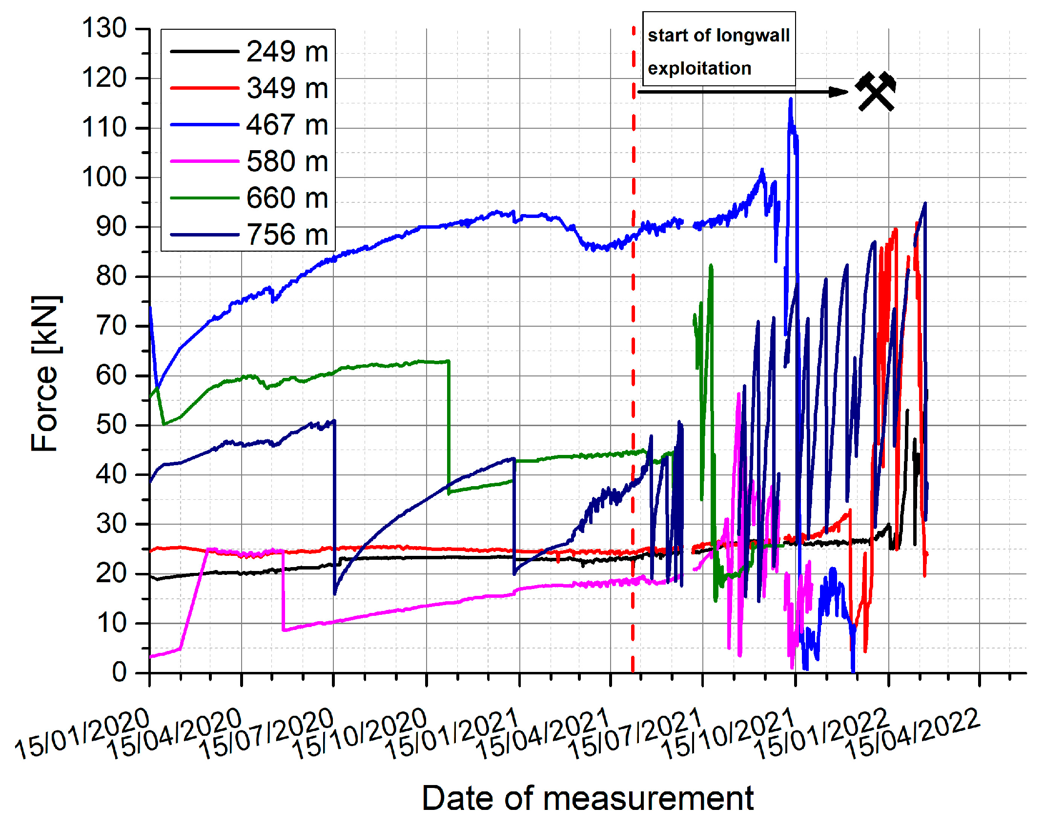
Monitoring of Bw-4 was conducted at six research stations—two for each tested support section (Figure 11). Based on the results analysis, it can be concluded that the first test section of the roadway (gauges installed at 249 m and 349 m of Bw-4) was, in the period before mining, stable. The maximum loads were 23.5 kN and 25.6 kN, consistent with the average load values of 22.3 kN and 24.7 kN. This was below the yielding value, which for the applied load cell was approximately 64 kN. During the longwall exploitation period, the frame maximum load values increased to 57.1 kN and 90.9 kN, respectively, indicating that it was yielding at the second station. Nevertheless, the average load values increased slightly to a maximum of 32 kN. From the curves presented in Figure 6, it can also be inferred that there was frame yielding, indicated by sudden drops in the recorded force. This situation occurred at 580, 660, and 758 m of the roadway ahead of the longwall face. However, when the longwall face passed the monitoring station, there was a sudden drop in force several times at every measurement station.
An interesting observation is that the loads on the wooden cribs (Figure 12) during the longwall exploitation were very low, ranging from 3 ÷ 15 kN. This indicates that the designed support systems successfully absorbed the loads from the rocks bending towards the goaf. This also applies to the load cell installed on base No. 4 on the second test section, for which the maximum value was 101.9 kN. This was also below the crib’s capacity, which was approximately 121 kN for the applied gauge. Unfortunately, the continuity of measurements was not maintained, due to some interruptions in electrical connectivity and the fact that the monitoring was conducted during the COVID-19 pandemic.
Even before the start of longwall exploitation, the cable strand bolts (Figure 13) were already transmitting high force values, reaching up to 175 kN. However, when subjected to abutment pressure, they were further loaded, reaching up to 235 kN. Consequently, in the case using 9 m strand bolts with significant deformability (the deformability of strand bolts is ca. 5%), the steel arch support was generally relieved. The yield of arches occurred only sporadically. The displacement chart of the roof rocks indicates that separation took place at test Section 1, while periodic compaction took place at Section 2 and Section 3 (Figure 14). So extendable strand bolts not fixed directly to the roof allowed for roof separation, but a roof bolted tightly by fully grouted bolts and cables and steel arches adjoined to the roof rocks, with the help of Bullflex bags, even lifted roof rocks a few centimetres upwards (this generally prevents arch slide). Then, the highest load was applied to cable bolts, while support frames were relieved.
Figure 15a–i present the results of Bw-4 cross-section scanning. The depicted graphs compare the shape of the excavation when the longwall both started (blue colour) and finished its run. The convergence of Bw-4 in test section I was minimal and mainly occurred on the longwall panel side. The width change averaged 50 ÷ 60 cm, the roof lowering was 10 ÷ 20 cm, and the average floor uplift was around 30 cm. Consequently, the cross-section decreased by approximately 21%. In test section II at chainage 500, the excavation contour was most deformed ahead of the longwall face, and the cross-section was the smallest. Local displacements were approximately 1.2 m in the roof, about 1.5 m on the right sidewall, about 0.2 m on the left sidewall, and there was a floor uplift of approximately 0.7 m. As a result, the excavation height was then around 2.0 ÷ 2.2 m, and the width decreased from 5.8 m to about 4 m. On average, the roadway cross-section decreased by approximately 36% behind the longwall face. The arch support contour in test section III also decreased from all directions behind the longwall face. The reduction in dimensions was from 0.5 to 1 m in the roof, from 0.7 to 1.1 m on the right sidewall, from 0.3 to 0.6 m on the left sidewall, and floor uplift was 0.9 ÷ 1.2 m. The highest roadway convergence at the third tested section of Bw-4 was obtained at chainage 650, where the cross-section decreased on average by about 32%.
It seems that the installation of very tight support frames, i.e., with tight lining, caused the load transfer from the roof and sidewalls to the floor and its considerable heaving. When comparing scanning results from tested sections II and III it is visible that a smoother shape of the roadway contour is evidenced in Section III. This was caused by another steel-yielding support yoke solution, which better allowed arch guidance, and sliding from one to another.
6.2. Monitoring of PW-1 Roadway
Monitoring of PW-1 was conducted at six measurement stations—namely two stations per roadway support test section. Based on the analysis of the results, it can be observed that on the first test section (gauges installed at chainage 225 and 280 m) after the roadway drivage, the steel arch support at 225 m had significantly more load than at 280 m (Figure 16). The maximum load at 225 m was 45 kN, while only 16 kN at 280 m. During longwall exploitation, the highest recorded force was approximately 72 kN, also at 280 m. A detailed interpretation of the results reveals the arch sliding phenomenon despite the relatively low load values. It suggests highly asymmetrical loads, especially on the sidewall arches, which were not monitored. Also, asymmetrical yielding can be interpreted from load cell values obtained at test section III (538 m and 605 m), where the maximum load reached as high as 71 kN, while only reaching 30 kN at the same time in the other cell. In the second test section the loads were the least, being no higher than 19 kN.
Notably, the load values recorded on the wooden cribs were significantly higher than those on the steel arch support (Figure 17). Only the crib located at 360 m recorded a load almost to the same extent as the steel arch support counterpart. In comparison, the loads on the wooden crib at 410 m (test section II) greatly exceeded the arch support loads (max. 170 kN) and approached its load-bearing capacity limit. In the second test section, bolting a larger roof area led to the redistribution of stresses on the sidewalls, including the wooden crib installed behind the longwall face, and simultaneously reduced the load on the support frames.
Measurements using measurement bolts illustrate the substantial loads carried by the bolt support (Figure 18), which were definitely higher at tested stations II and III. The maximum total load was reached at chainage 610 m—320 kN, and at chainage 362 m—272 kN and chainages 412 m and 542 m—230 ÷ 240 kN. This proves that the load of the damage zone in the roof was mainly carried by strand bolts.
Displacement measurements of the roof, initiated a few months after the roadway excavation, showed small values ranging from 6.6 cm ahead to 10.2 cm behind the longwall face, but only in the tested Section I (Figure 19), where strand bolts on resin cartridges were installed. The separation of roof rocks in tested sections II and III, where cable bolts where injected, was considerably smaller. Using Bullflex bags on the roof arches in Section II caused roof bed movements in both directions and a further decrease in the roof rock separation.
Due to technical reasons, stress change measurement, both ahead and behind the longwall face, was feasible only at one measurement base located in the second test section (Figure 20). The roof reinforcement, with the help of bolts and their stiffening, resulted in increasing horizontal pressures toward the developing goaf. The stress direction ahead of the longwall face was changing constantly, causing variations in the loading directions on the support (Figure 21). This was one of the reasons why the steel arch support experienced less load due to a reduction in vertical pressure. Additionally, stress changes ahead of the longwall face practically doubled the value of primary stresses. At a depth of approximately 900 m (σz = 22.5 MPa), the increase was around 20 MPa. Therefore, if the rock mass is not heavily cracked and relieved, and there is no significant rotation of stress direction, such a situation is possible. However, it is crucial to note that at a triaxial stress state, the higher stress is primarily carried by the rock mass itself. Hence it has minimal impact on the load of a frame support in a gateroad.
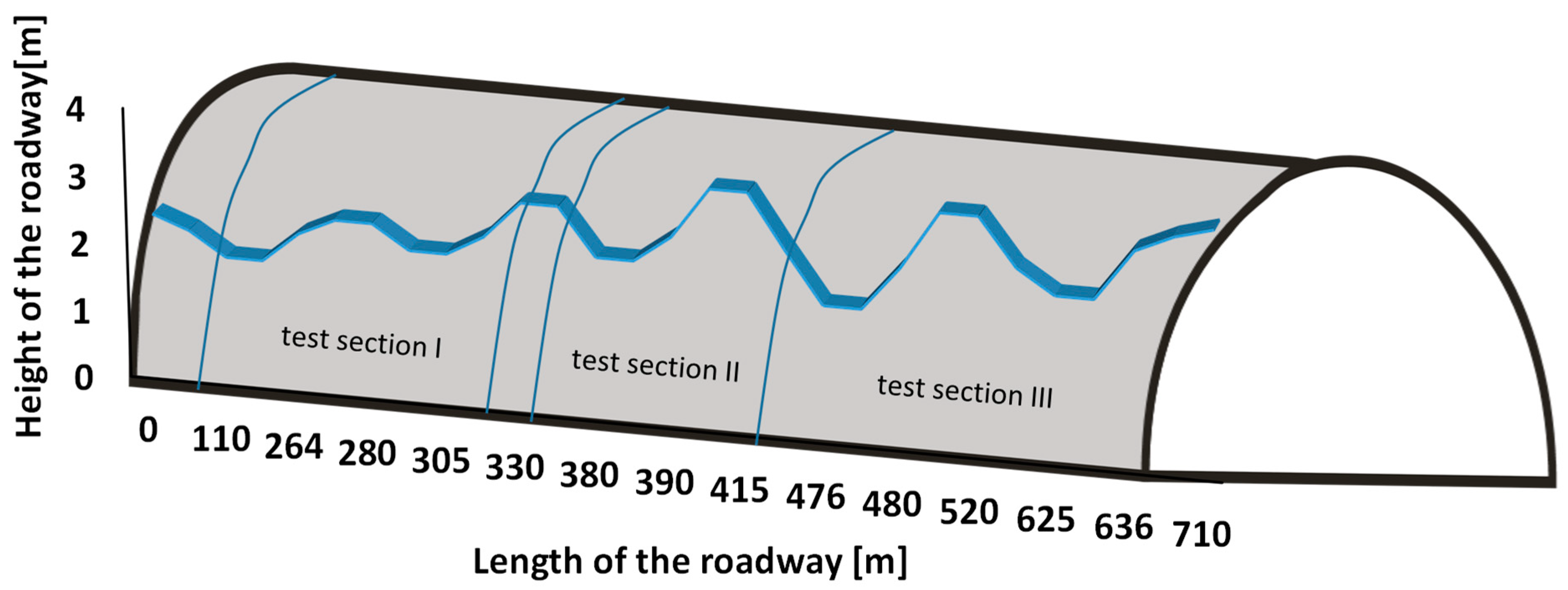
After the longwall panel operation, measurements of the roadway height were conducted. The results are presented in Figure 22, where test sections are indicated: test section I, where the basic support scheme used from the mine was applied; and test sections II and III, where new designed support schemes were checked. It can be observed that the most significant height changes in the roadway occurred in the first test section. In this particular section, after exploitation, the roadway height was only 1.8 m, with a weighted average of 1.99 m, while its initial height was 4.1 m. In the second and third test sections, where new support solutions were applied, the roadway dimensions were approximate: in Section II around 2.6 ÷ 2.8 m (in some places even 3.6 m), and in Section III around 2.6 ÷ 2.9 m (in some places even 3.5 m) was recorded. Despite high loads being recorded there during monitoring, the maximum height reduction of the roadway was 2.3 m at the second section, and 1.9 m at the third section. The use of grouted pre-tensioned Titan bolts effectively helped to maintain the roadway dimensions in difficult mining conditions. The average height of PW-1 y in Section II was 2.97 m, and was 2.71 m in Section III.
In general, the second and third experimental sections of PW-1 exhibited significantly better stability after the longwall exploitation, compared to the first section, where the strand bolts installed in two resin cartridges were used.
Based on the results of changes in the cross-sectional dimensions of both Bw-4 and PW-1, it can be observed that locally significant deformations occurred, reaching up to 2 m. In contrast, Liu et al. [31] showed deformation results of roadways maintained behind the longwall face, with maximum levels reaching only 0.328 m. However, the study was conducted using only one support scheme—steel-yielding support with roof rock bolts installed from the goaf side. In a different study, Xiao Ming et al. [32] demonstrated that the load on the rock bolt support directly behind the longwall face reached up to 500 kN while further away from the longwall face, this value dropped to around 300 kN. In this case, the research focused on rockbolting only, resulting in the recording of high load values. Of the two tested roadways, only one rock bolt was maximally loaded up to 320 kN in PW-1, while in Bw-4 it was a maximum of 235 kN. In both maingates, after these loads were obtained, long strand bolts were only installed on two resin cartridges. These values can be successfully transferred by cable strand bolts, commonly used in Polish mining. However, using fully grouted cable bolts does decrease the maximum bolt loads. Moreover, the additional use of pre-tensioning ensures the maintenance of a greater roadway height behind the longwall face, which was proved in PW-1.
7. Conclusions
Summarizing the conducted analyses and testing, the following conclusions can be formulated:
- A four-stage design of roadways support is essential if the gateroad has to be maintained behind the longwall face. This involves (1) evaluating rock mass quality, (2) assessing the effectiveness of design and roadway maintenance, (3) verifying designed support after its drivage by endoscopic research (ERMF index), and (4) carrying out rock-mass and support monitoring. Only monitoring can give feedback for the designed support scheme.
- Using pre-tensioned and Gifford-clamped fully grouted cable bolts enables the maintenance of roadway dimensions, even in very challenging roof conditions, as encountered in PW-1. The bolts compressing the roof rocks create a load-bearing roof rock beam, resulting in less roof sagging and ensuring higher roadway height, compared to areas without this bolting. Additionally, grouting both binds and strengthens fractured rock around the bolts.
- Implementing a steel yielding arch support with an innovative yoke solution improves the problem of arch sliding. Better arch adjacency and better guidance during their shear movements will improve the yield reaction. The sliding is more symmetrical, and the frame maintains an arched profile, even under abutment pressures. Using this solution prevents significant flattening of roof arches and disruption or blocking at the contact points between roof and sidewall arches.
- Evaluating the stability of roadways in the light of the applied support schemes indicates that the key to maintaining roadway dimensions at great depth is using short steel rock bolts and long cable strand bolts. This reinforcement creates a bolted load-bearing beam in the roof, transferring stresses to the sidewalls and then to the floor. The deeper the redistribution of the stress in the rock mass, the less deformation of the roadway contour is to be expected. If the stress is redistributed just on both sidewalls to a shallow depth, the deformations can be considerable (including floor heaving). The use of Bullflex bags on the roof arches can even cause plastic steel frame deformations, if its yield strength is too low when carrying a remarkable load.
- Using strand bolts, which are only installed at their end with the help of two resin cartridges, allows for separation of roof beds. Then the load on steel frames is significant and its yielding can be visible. The yield depends strictly on the load direction, which is usually not vertical. The roadway contour undergoes a less pronounced dimension reduction as a result.
- The research project demonstrated the effectiveness of using steel arch and rock bolt support. Bolting the roof creates a roof beam, which delays rock bed deflection and decreases the load on a roof arch of standing support. The way the roof layers lean on the support frame causes the rock bolts to reduce their load. The combination of two different types of support can effectively ensure the stability of roadways maintained behind the longwall face for a specified period.
- The presented research revealed the scientific and practical aspects of phenomena occurring near the advancing longwall face, both in the support and rock mass. Subsequent studies should also include measurements of rock mass stresses in the roadway’s roof and floor. These measurements should be taken at various distances from its contour. The results of such analyses can allow for the verification of numerical solutions, thereby optimizing the structural design of support in the gateroads, as the gateroads’ support design is one of the most challenging tasks of mine operations.
Author Contributions
Conceptualization, Ł.B., P.M. and Z.N.; Methodology, Ł.B., P.M. and Z.N.; Formal analysis, Ł.B. and P.M.; Investigation, Ł.B., P.M. and Z.N.; Resources, Ł.B.; Writing—original draft, Ł.B., P.M., Z.N. and K.M.; Writing—review & editing, K.M.; Visualization, Ł.B.; Supervision, P.M. and Z.N.; Project administration, K.M. All authors have read and agreed to the published version of the manuscript.
Funding
This research received no external funding.
Institutional Review Board Statement
Not applicable.
Informed Consent Statement
Not applicable.
Data Availability Statement
The data presented in this study are available in the article.
Conflicts of Interest
The authors declare no conflict of interest.
References
- Jiang, L.; Zhang, P.; Chen, L.; Hao, Z.; Sainoki, A.; Mitri, H.S.; Wang, Q. Numerical Approach for Goaf-Side Entry Layout and Yield Pillar Design in Fractured Ground Conditions. Rock Mech. Rock Eng. 2017, 50, 3049–3071. [Google Scholar] [CrossRef]
- Qian, D.; Zhang, N.; Shimada, H.; Wang, C.; Sasaoka, T.; Zhang, N. Stability of goaf-side entry driving in 800-m-deep island longwall coal face in underground coal mine. Arab. J. Geosci. 2016, 9, 82. [Google Scholar] [CrossRef]
- Prusek, S. Changes in cross-sectional area of gateroads in longwalls with roof caving, ventilated with “U” and “Y” systems. Arch. Min. Sci. 2015, 60, 549–564. [Google Scholar] [CrossRef]
- Qian, D.; Shimada, H.; Zhang, Z.; Sasaoka, T.; Matsui, K. Application of goaf-side roadway retained and new type ventilation system in deep longwall face. Mem. Fac. Eng. Kyushu Univ. 2015, 74, 99–116. [Google Scholar]
- Zhang, Z.; Zhang, N.; Shimada, H.; Sasaoka, T.; Wahyudi, S. Optimization of hard roof structure over retained goaf-side gateroad by pre-split blasting technology. Int. J. Rock Mech. Min. Sci. 2017, 100, 330–337. [Google Scholar] [CrossRef]
- Shao, L.; Huang, B.; Zhao, X. Secondary Gob-side Entry Retaining Technology with Double Side Roof Cutting and Pressure Relief in Thin Coal Seam. Int. J. Oil Gas Coal Eng. 2020, 8, 91. [Google Scholar] [CrossRef]
- Rak, Z. Good practices in maintaining the roadways in one-sided surroundings of caving goaf. Gospod. Surowcami Miner.—Miner. Resour. Manag. 2017, 101, 117–132. [Google Scholar]
- Chen, S.; Lv, Q.; Yuan, Y. Key Technologies and its Application of Gob-Side Entry Retaining by Roof Cutting in a Deep Mine. Arch. Min. Sci. 2022, 67, 55–77. [Google Scholar] [CrossRef]
- Masny, W.; Rajwa, S.; Prusek, S.; Łukawski, S.; Kocel, M. Utrzymanie chodnika przyścianowego za frontem ściany na dużych głębokościach—Analiza przypadku. Przegląd Górniczy 2016, 72, 1–11. (In Polish) [Google Scholar]
- Duży, S.; Gluch, P.; Michalik, G.; Ratajczak, A. Effectiveness of bolting for wall and heading crossings in light of the Knurów–Szczygłowice Coal Mine experience. Gospod. Surowcami Miner.—Miner. Resour. Manag. 2018, 103, 103–116. [Google Scholar] [CrossRef]
- Xie, S.R.; Pan, H.; Chen, D.D.; Zeng, J.C.; Song, H.Z.; Cheng, Q.; Xiao, H.B.; Yan, Z.Q.; Li, Y.H. Stability analysis of integral load-bearing structure of surrounding rock of gob-side entry retention with flexible concrete formwork. Tunn. Undergr. Space Technol. 2020, 103, 103492. [Google Scholar] [CrossRef]
- Liu, J.; He, M.; Wang, Y.; Huang, R.; Yang, J.; Tian, X.; Ming, C.; Guo, S. Stability Analysis and Monitoring Method for the Key Block Structure of the Basic Roof of Noncoal Pillar Mining with Automatically Formed Gob-Side Entry. Adv. Civ. Eng. 2019, 2019, 5347683. [Google Scholar] [CrossRef]
- Tian, X.; Wang, J.; Yu, G.; Wang, H.; Liu, P.; Pan, Z.; Wang, Y. Research and application of Gob-Side entry retaining with roof presplitting under residual coal pillar of upper coal seam. Energy Explor. Exploit. 2022, 40, 1494–1521. [Google Scholar] [CrossRef]
- Xie, S.; Wang, E.; Chen, D.; Li, H.; Jiang, Z.; Yang, H. Stability analysis and control technology of gob-side entry retaining with double roadways by filling with high-water material in gently inclined coal seam. Int. J. Coal Sci. Technol. 2022, 9, 52. [Google Scholar] [CrossRef]
- Zhang, Z.; Guan, W.; Chen, H. Numerical Study on the Effectiveness of the Grouting Cable Bolt in Deep Retained Goaf Side Gateroad. Geotech. Geol. Eng. 2020, 38, 4529–4543. [Google Scholar] [CrossRef]
- Fu, W. Study on Surrounding Rock Control of Gob-Side Entry Retaining in Inclined and Thick Longwall Face. Geotech. Geol. Eng. 2022, 40, 3477–3491. [Google Scholar] [CrossRef]
- Wu, R.; Zhang, P.; Kulatilake, P.H.S.W.; Luo, H.; He, Q. Stress and deformation analysis of gob-side pre-backfill driving procedure of longwall mining: A case study. Int. J. Coal Sci. Technol. 2021, 8, 1351–1370. [Google Scholar] [CrossRef]
- Guo, P.; Zhang, X.; Peng, Y.; He, M.; Ma, C.; Sun, D. Research on Deformation Characteristic and Stability Control of Surrounding Rock During Gob-Side Entry Retaining. Geotech. Geol. Eng. 2020, 38, 2887–2902. [Google Scholar] [CrossRef]
- Yang, G.; Yang, X.; Zhang, J.; He, M.; Hao, Z.; Yang, F.; Shao, J. Effect of Roof Cutting Technology on Broken Roof Rock Bulking and Abutment Stress Distribution: A Physical Model Test. Rock Mech. Rock Eng. 2024. [Google Scholar] [CrossRef]
- Waclawik, P.; Kukutsch, R.; Konicek, P.; Ptacek, J.; Kajzar, V.; Nemcik, J.; Stas, L.; Soucek, K.; Vavro, M. Stress State Monitoring in the Surroundings of the Roadway Ahead of Longwall Mining. Procedia Eng. 2017, 191, 560–567. [Google Scholar] [CrossRef]
- Guangchao, Z.; Chuanwei, Z.; Miao, C.; Guangzhe, T.; You, L.; Weihua, H.; Hongzhou, W.; Deshuai, Z. Ground response of entries driven adjacent to a retreating longwall panel. Int. J. Rock Mech. Min. Sci. 2021, 138, 104630. [Google Scholar] [CrossRef]
- Yu, Y.; Bai, J.; Wang, X.; Zhang, L. Control of the surrounding rock of a goaf-side entry driving heading mining face. Sustainability 2020, 12, 2623. [Google Scholar] [CrossRef]
- Iannacchione, A.; Prosser, L.; Esterhuizen, G.; Bajpayee, T. Methods for determining roof fall risk in underground mines. Min. Eng. 2007, 59, 47–53. [Google Scholar]
- Laubscher, H. A geomechanics classification system for the rating of rock mass in mine design. J. South Afr. Inst. Min. Metall. 1991, 28, A228. [Google Scholar] [CrossRef]
- Mark, C.; Molinda, G.M. Development and application of the coal mine roof rating (CMRR). In Proceedings of the International Workshop on Rock Mass Classification in Underground Mining; U.S. Department of Health and Human Services, Public Health Service, Centers for Disease Control and Prevention, National Institute for Occupational Safety and Health: Washington, DC, USA, 2007; pp. 95–110. [Google Scholar]
- Bednarek, Ł.; Majcherczyk, T. An analysis of rock mass characteristics which influence the choice of support. Geomech. Eng. 2020, 21, 31–377. [Google Scholar] [CrossRef]
- Małkowski, P.; Niedbalski, Z.; Majcherczyk, T. Roadway design efficiency indices for hard coal mines. Acta Geodyn. Geomater. 2016, 13, 201–211. [Google Scholar] [CrossRef]
- Niedbalski, Z.; Majcherczyk, T. Indicative assessment of design efficiency of mining roadways. J. Sustain. Min. 2018, 17, 131–138. [Google Scholar] [CrossRef]
- Majcherczyk, T.; Małkowski, P.; Niedbalski, Z. Describing Quality of Rocks around Underground Headings: Endoscopic Observations of Fractures. In Proceedings of the ISRM International Symposium—EUROCK, Brno, Czech Republic, 18–20 May 2005; p. ISRM-EUROCK-2005-058. [Google Scholar]
- Małkowski, P.; Niedbalski, Z.; Majcherczyk, T. Endoscopic method of rock mass quality evaluation—New experiences. In Proceedings of the 42nd U.S. Rock Mechanics—2nd U.S.-Canada Rock Mechanics Symposium 2008, San Francisco, CA, USA, 29 June–2 July 2008. [Google Scholar]
- Liu, H.; Zhang, B.; Li, X.; Liu, C.; Wang, C.; Wang, F.; Chen, D. Research on roof damage mechanism and control technology of gob-side entry retaining under close distance gob. Eng. Fail. Anal. 2022, 138, 106331. [Google Scholar] [CrossRef]
- Sun, X.-m.; Li, G.; Song, P.; Miao, C.; Zhao, C.; Li, Q.; Xia, X. Application Research on Gob-Side Entry Retaining Methods in No. 1200 Working Face in Zhongxing Mine. Geotech. Geol. Eng. 2019, 37, 185–200. [Google Scholar] [CrossRef]
Figure 1.
Longwall system with: (a) a pillar between gates, (b) no pillar between gates—the double use of the same gateroad.
Figure 1.
Longwall system with: (a) a pillar between gates, (b) no pillar between gates—the double use of the same gateroad.

Figure 2.
Rock mass displacement zones around the roadway: 1—collapse zone, 2—fracture zone, 3—continuous displacement zone.
Figure 2.
Rock mass displacement zones around the roadway: 1—collapse zone, 2—fracture zone, 3—continuous displacement zone.
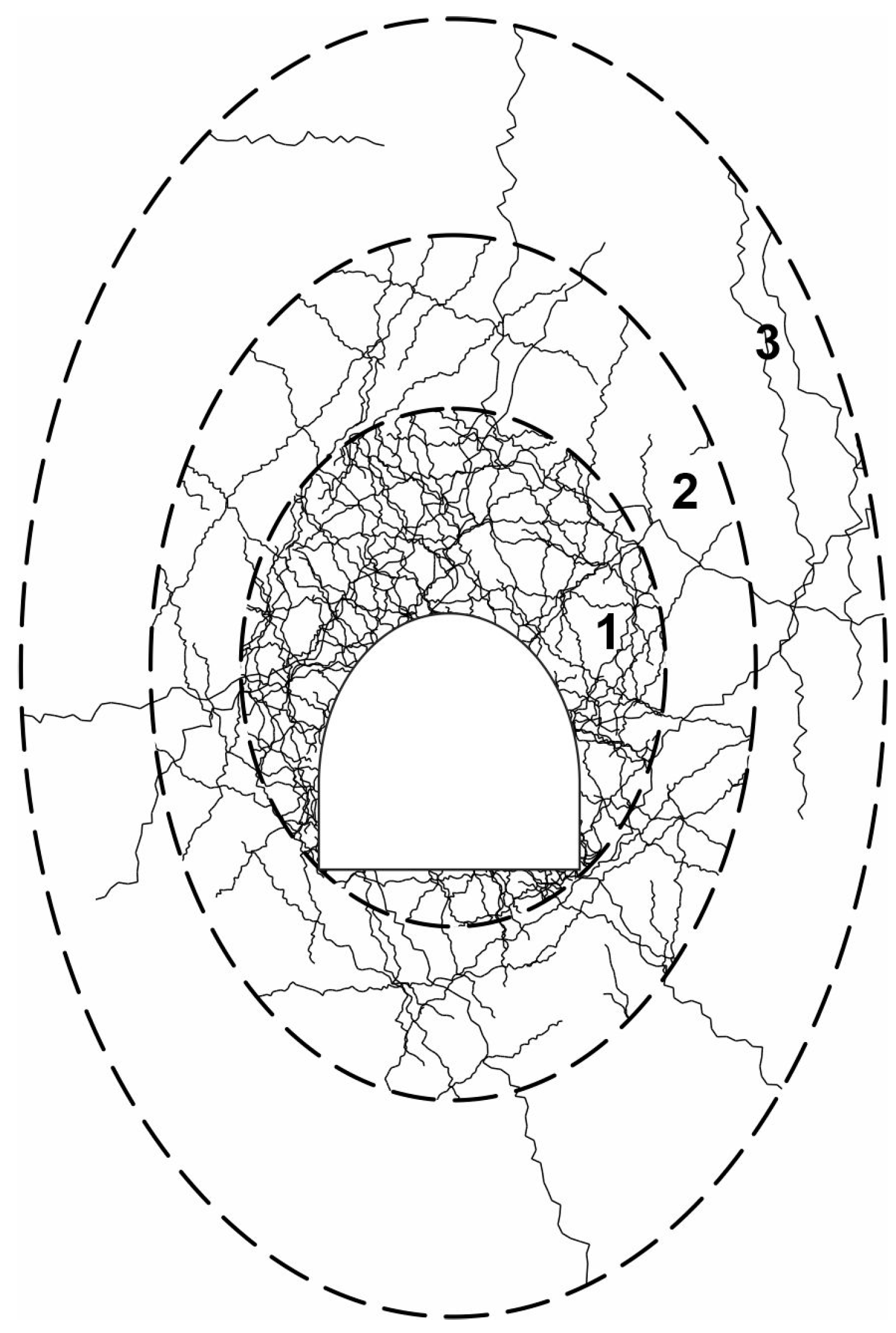
Figure 3.
Map of the vertical stresses indicating: (a) the range of fracture zone; (b) the Bw-4 roadway ahead of the longwall face.
Figure 3.
Map of the vertical stresses indicating: (a) the range of fracture zone; (b) the Bw-4 roadway ahead of the longwall face.

Figure 4.
Map of the vertical stresses: (a) the range of fracture zone; (b) the Bw-4 roadway behind the longwall face.
Figure 4.
Map of the vertical stresses: (a) the range of fracture zone; (b) the Bw-4 roadway behind the longwall face.
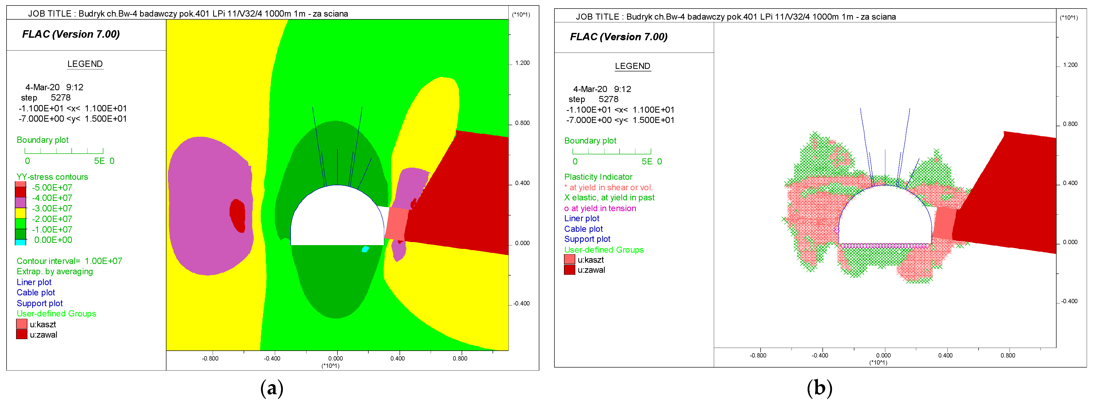
Figure 5.
Map of the vertical stresses (a) and the range of fracture zone (b) in PW-1 roadway ahead the longwall face.
Figure 5.
Map of the vertical stresses (a) and the range of fracture zone (b) in PW-1 roadway ahead the longwall face.

Figure 6.
Map of the vertical stresses: (a) the range of the fracture zone; (b) the PW-1 roadway behind the longwall face.
Figure 6.
Map of the vertical stresses: (a) the range of the fracture zone; (b) the PW-1 roadway behind the longwall face.
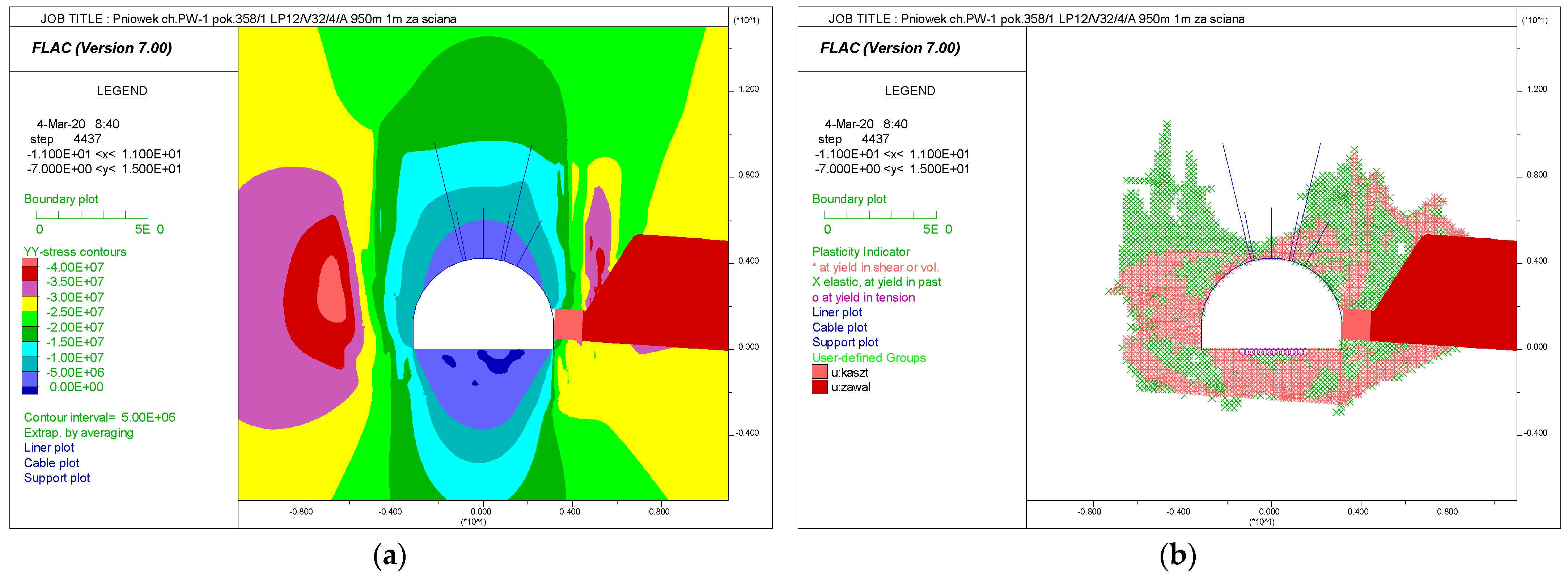
Figure 7.
New support elements: (a). Titan cable strand bolt (DSI Underground); (b). the ŁPi roof arch, with a groove blocking the lower yoke movement (on the right side—the zoom of element A), L—the lenght of the roof arch, R—the arch radius.
Figure 7.
New support elements: (a). Titan cable strand bolt (DSI Underground); (b). the ŁPi roof arch, with a groove blocking the lower yoke movement (on the right side—the zoom of element A), L—the lenght of the roof arch, R—the arch radius.
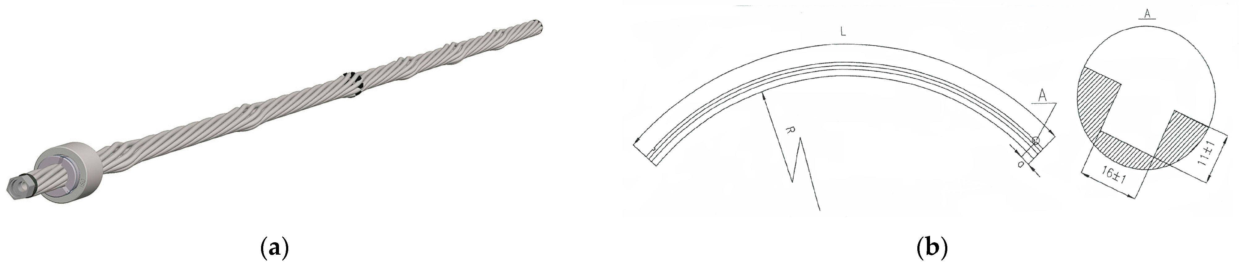
Figure 8.
Support schemes in Bw-4 roadway: (a) Test section I, (b) Test section II, (c) Test section III.
Figure 8.
Support schemes in Bw-4 roadway: (a) Test section I, (b) Test section II, (c) Test section III.
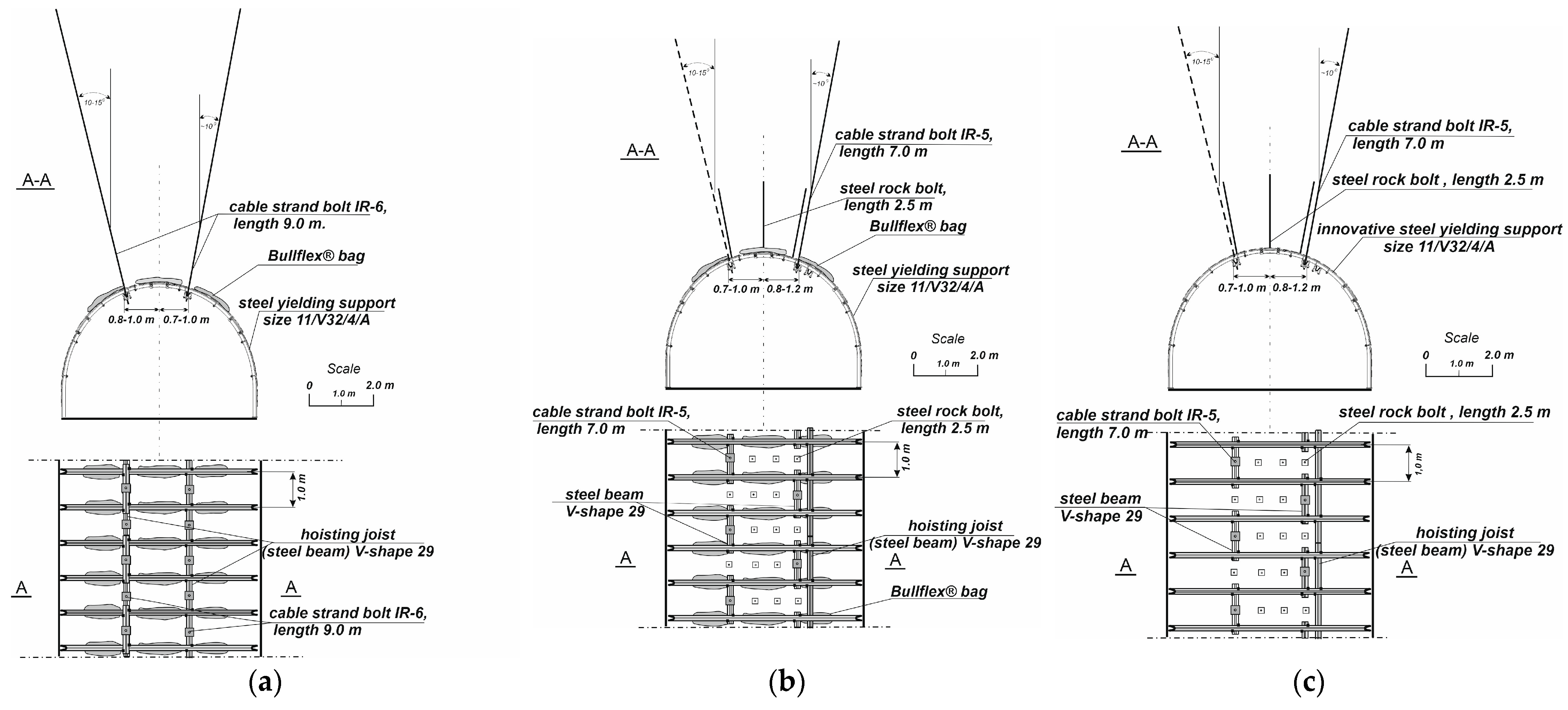
Figure 9.
Support schemes in PW-1 roadway: (a) Test section I, (b) Test section II, (c) Test section III.
Figure 9.
Support schemes in PW-1 roadway: (a) Test section I, (b) Test section II, (c) Test section III.

Figure 10.
Monitoring station scheme: u—roof beds separation, Pk—the bolt load, Q—the load on a sensor.
Figure 10.
Monitoring station scheme: u—roof beds separation, Pk—the bolt load, Q—the load on a sensor.
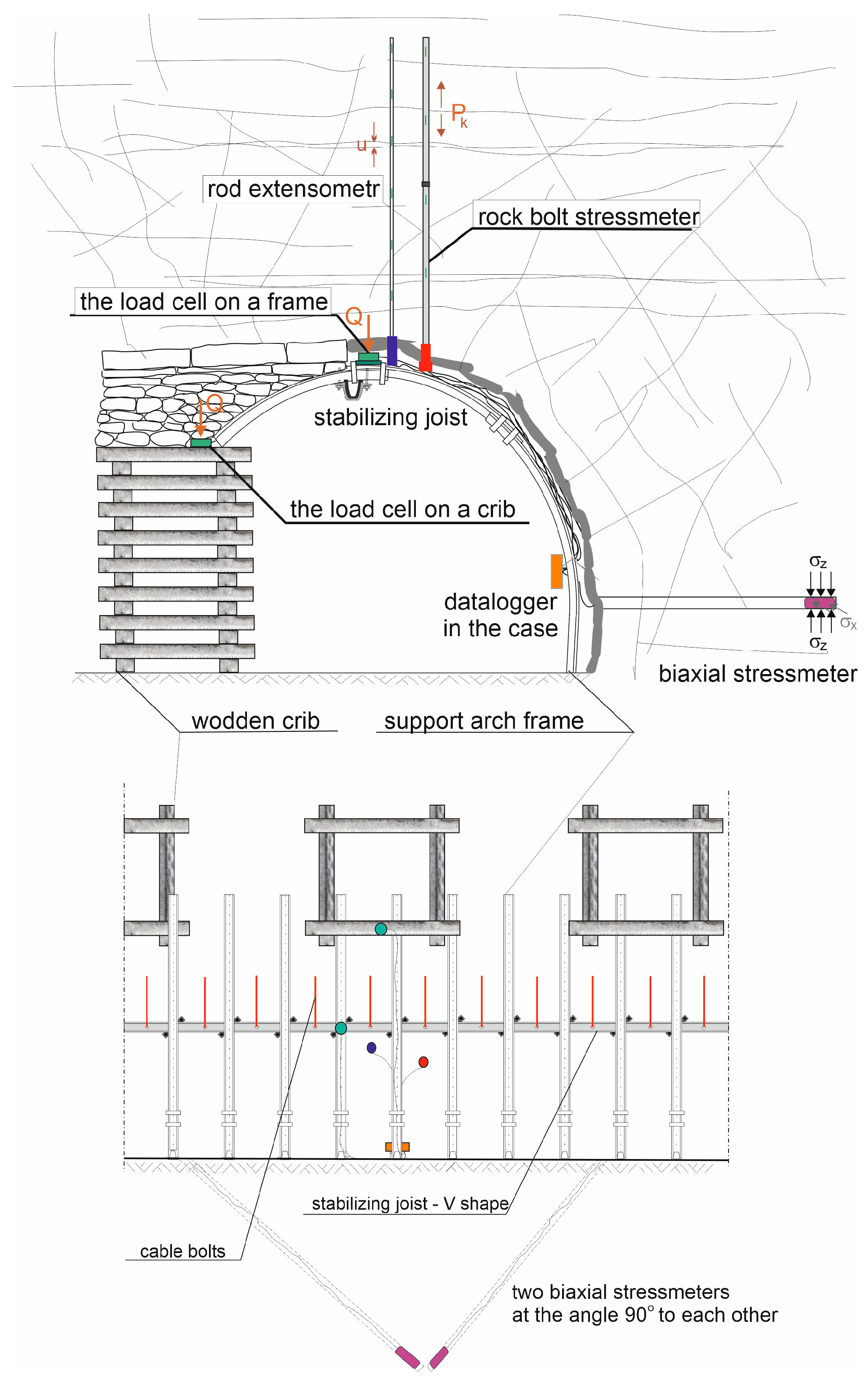
Figure 11.
Measurement results obtained from the load cells installed on the steel arch support in Bw-4 roadway.
Figure 11.
Measurement results obtained from the load cells installed on the steel arch support in Bw-4 roadway.

Figure 12.
Measurement results obtained from the load cells installed on the wooden cribs in Bw-4 roadway.
Figure 12.
Measurement results obtained from the load cells installed on the wooden cribs in Bw-4 roadway.

Figure 13.
Total load along the bolt in Bw-4 roadway.
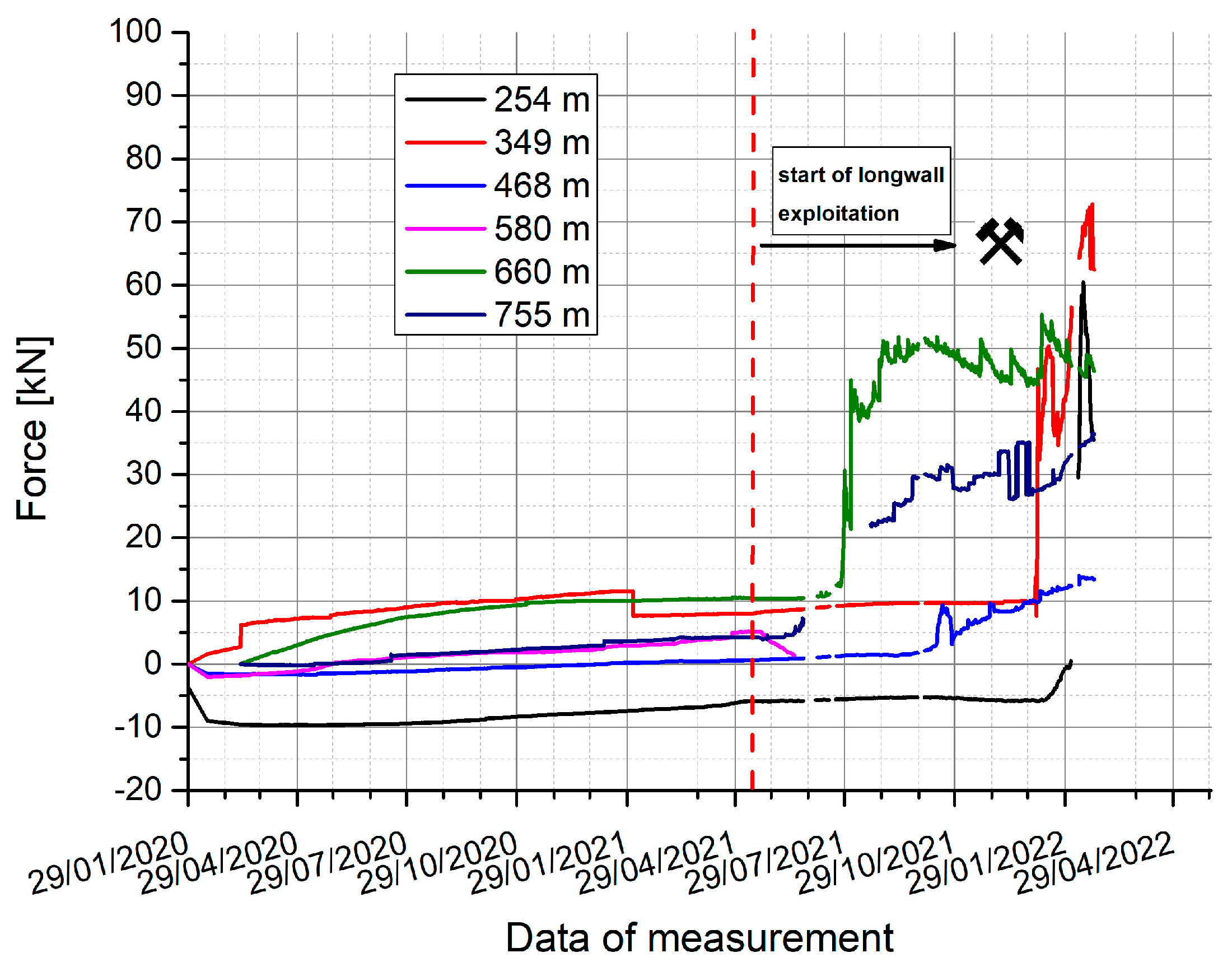
Figure 14.
Total displacement of rock layers in Bw-4 roadway.
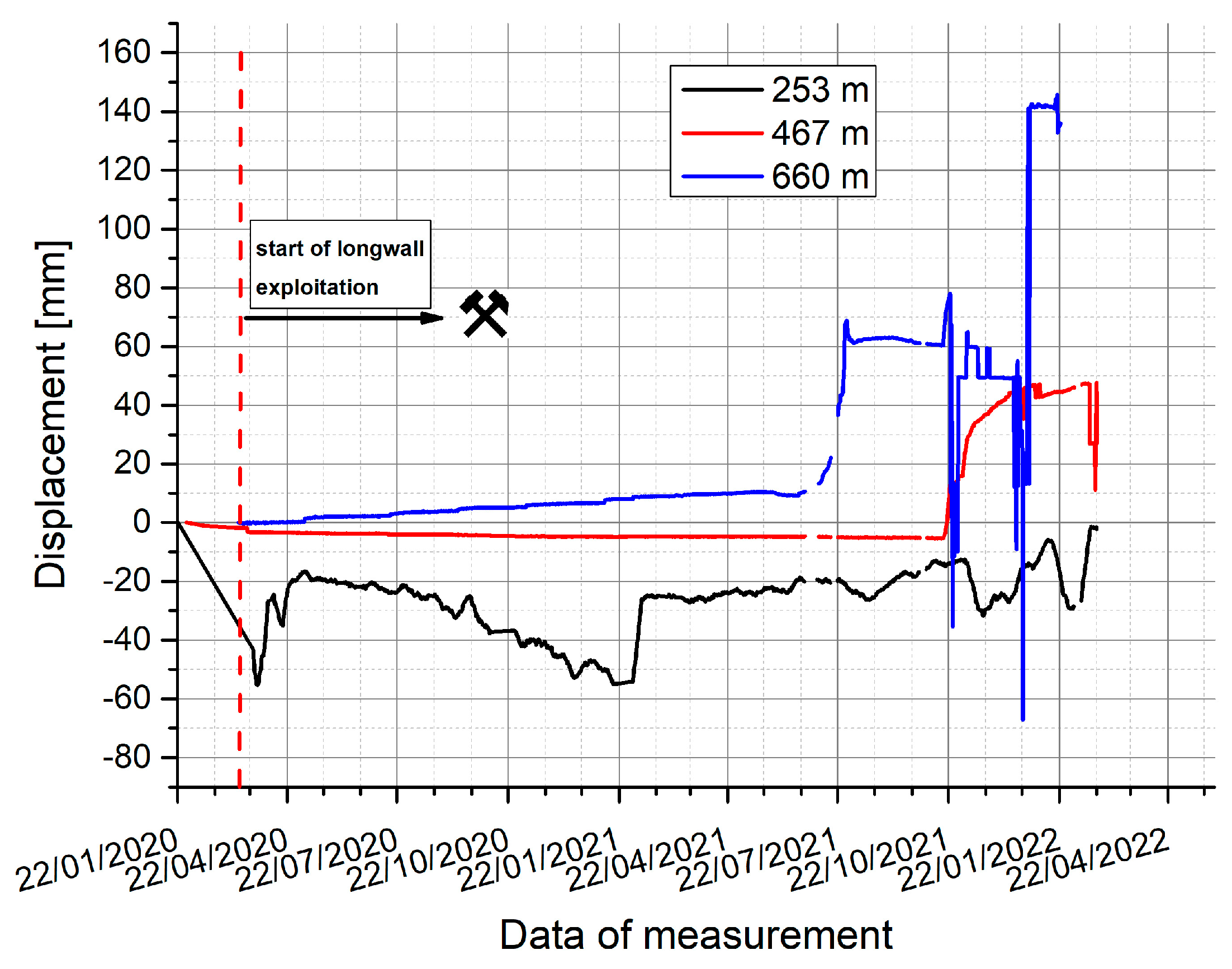
Figure 15.
Results of laser scanning in Bw-4 roadway, ahead (blue) and behind (red) the longwall face at chainage: (a) 250 m, (b) 300 m, (c) 350 m, (d) 450 m, (e) 500 m, (f) 550 m, (g) 650 m, (h) 700 m, (i) 750 m.
Figure 15.
Results of laser scanning in Bw-4 roadway, ahead (blue) and behind (red) the longwall face at chainage: (a) 250 m, (b) 300 m, (c) 350 m, (d) 450 m, (e) 500 m, (f) 550 m, (g) 650 m, (h) 700 m, (i) 750 m.


Figure 16.
Measurement results obtained from the load cells installed on the roof arch of support frames in PW-1 roadway.
Figure 16.
Measurement results obtained from the load cells installed on the roof arch of support frames in PW-1 roadway.
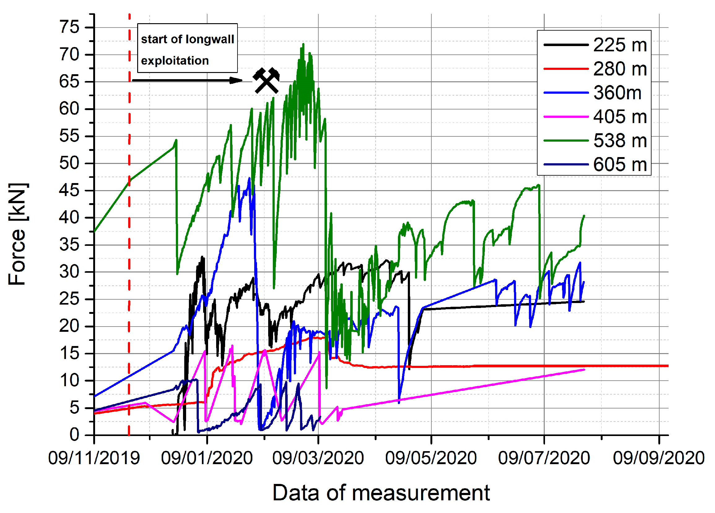
Figure 17.
Measurement results obtained from the load cells installed on wooden cribs in PW-1 roadway.
Figure 17.
Measurement results obtained from the load cells installed on wooden cribs in PW-1 roadway.
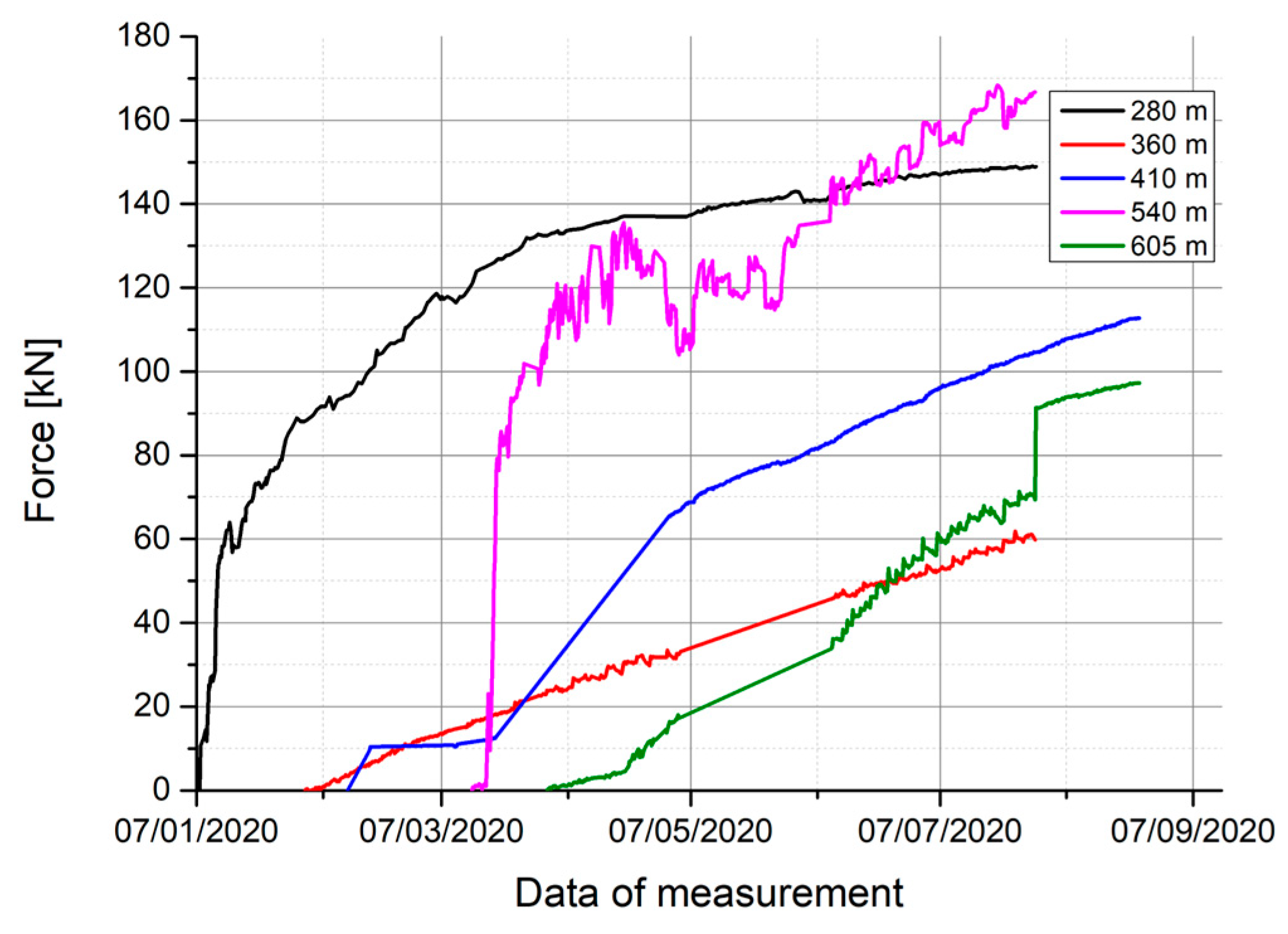
Figure 18.
Total load on the measuring bolt along its entire length in the PW-1 roadway.
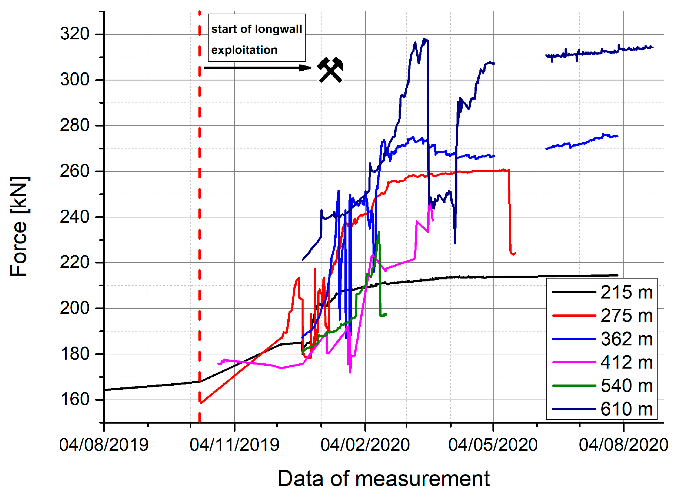
Figure 19.
Total displacement of roof rock beds in PW-1 roadway.
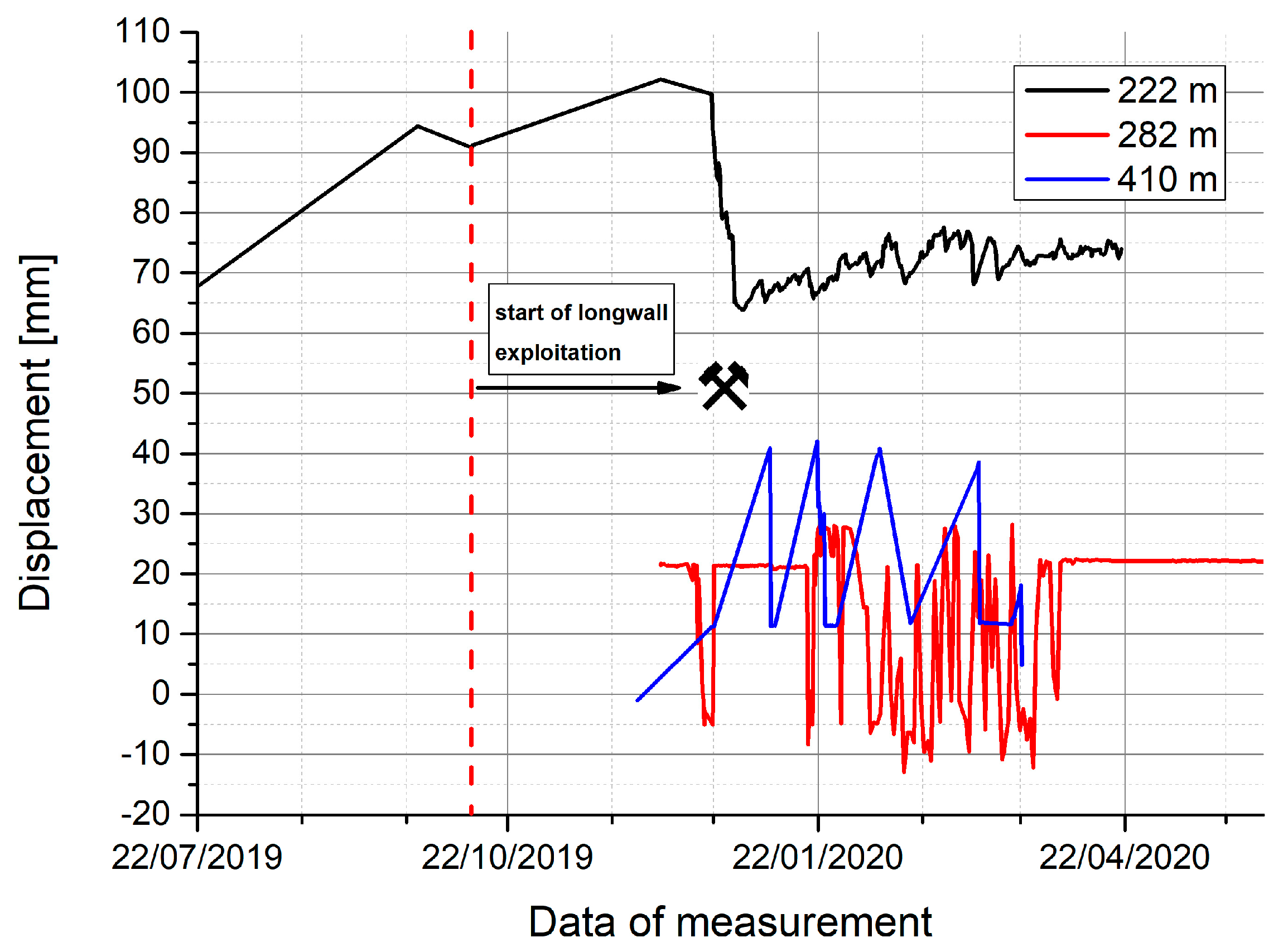
Figure 20.
Change of principal stresses in the rock mass around PW-1 roadway.

Figure 21.
Change of the angle between the resultant and vertical axis.
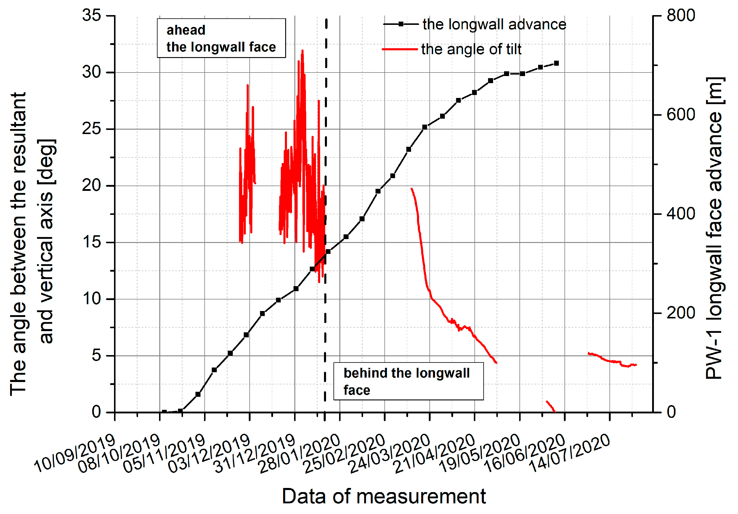
Figure 22.
Change of height in the PW-1 roadway behind the longwall exploitation.

Table 1.
Geomechanical rock properties.
| Roadway | Rock Bed | Unit Weight γ [kN/m3] | Young Modulus E [GPa] | Poisson Ratio ν [-] | UCS [MPa] | Tensile Strength [MPa] |
|---|---|---|---|---|---|---|
| Bw-4 | shale | 26.42–26.61 | 7.88–9.52 | 0.21–0.22 | 25–35 | 1.6–2.58 |
| sandstone | 24.71 | 9.12 | 0.22 | 37.3 | 2.49 | |
| coal | 12.62 | 1.77 | 0.30 | 20.9 | 0.33 | |
| PW-1 | shale | 25.1–26.1 | 4.81–6.27 | 0.26 | 25.7–32.7 | 1.93–2.42 |
| mudstone | 26.3 | 6.73 | 0.22 | 36.3 | 2.83 | |
| sandstone | 26.1 | 9.99 | 0.20 | 42.6 | 2.84 | |
| coal | 12.2 | 2.10 | 0.30 | 7.2 | 0.46 |
Table 2.
Suggestion for the reinforcements of the roof support scheme, depending on the anticipated scenario.
Table 2.
Suggestion for the reinforcements of the roof support scheme, depending on the anticipated scenario.
| Parameter | Reinforcement Scenario for Steel Arch Support | |||
|---|---|---|---|---|
| I | II | III | IV | |
| <1 | ≥1 | <1 | ≥1 | |
| >0 | >0 | ≤0 | ≤0 | |
| Additional reinforcement for the support scheme | No reinforcement | Rock bolts or cable strand bolts | Yielding arch support of high steel grade, rock bolts or cables and hoisting joists (steel beams) | Yielding arch support of high steel grade, hoisting joists fixed to the roof with the help of high-bearing capacity strand cable bolts |
Table 3.
List of parameters in the tested roadways with the forecast scenario.
| Roadway | Chainage [m] | H [m] | UCS [MPa] | Number of Cracks ls [-] | Number of Layers lw [-] | n | WL | Hkr [m] | Forecast Scenario | ||
|---|---|---|---|---|---|---|---|---|---|---|---|
| Bw-4 | 250 | 1050 | 37.30 | 22 | 2 | 11.00 | 1.00 | 690 | YES | NO | IV |
| 354 | 1050 | 34.10 | 24 | 9 | 2.66 | 0.67 | 631 | YES | NO | IV | |
| 469 | 1050 | 32.90 | 3 | 3 | 1.00 | 0.72 | 609 | YES | NO | IV | |
| 580 | 1050 | 39.90 | 11 | 2 | 5.50 | 0.66 | 738 | YES | NO | IV | |
| 658 | 1050 | 27.50 | 21 | 2 | 10.50 | 0.66 | 509 | YES | NO | IV | |
| 754 | 1050 | 31.50 | 3 | 1 | 3.00 | 0.66 | 583 | YES | NO | IV | |
| PW-1 | 275 | 950 | 29.23 | 95 | 6 | 15.83 | 0.72 | 541 | YES | NO | IV |
| 358 | 950 | 34.67 | 89 | 6 | 14.83 | 0.76 | 642 | YES | NO | IV | |
| 570 | 950 | 22.06 | 34 | 8 | 4.25 | 0.74 | 408 | YES | NO | IV |
Table 4.
Effectiveness of maintaining roadways in hard coal mines.
| Class | Description | RFM [Points] |
|---|---|---|
| I | Easy possibility of maintaining the roadway for a specified period | 86–100 |
| II | Maintenance of the roadway for a specified period without significant difficulties | 71–85 |
| III | Maintenance of the roadway for a specified period with some difficulties | 56–70 |
| IV | Difficulties in maintaining the roadway for a specified period | 41–55 |
| V | Significant difficulties in maintaining the roadway for a specified period | 26–40 |
| VI | No possibility of maintaining the roadway | 5–25 |
Table 5.
Comparison of the Roadway Design Efficiency index (RDE) and the Roadway Functionality Maintenance index (RFM) for the analysed roadways.
Table 5.
Comparison of the Roadway Design Efficiency index (RDE) and the Roadway Functionality Maintenance index (RFM) for the analysed roadways.
| Roadway | Tested Section [m] | Geological Factors | Geomechanical Rock Properties | Mining Factors | RDE | RDE Class | Technical Conditions | RFM | RFM Class |
|---|---|---|---|---|---|---|---|---|---|
| [Points] | [Points] | ||||||||
| Bw-4 | 200–400 | 77.68 | 62.48 | 62.96 | 203.1 | III | 81.98 | 56 | III |
| 400–600 | 81.76 | 53.98 | 62.96 | 198.7 | III | 90.24 | 60 | III | |
| 600–800 | 87.34 | 53.98 | 62.96 | 204.3 | III | 86.28 | 59 | III | |
| PW-1 | 100–329 | 84.00 | 62.48 | 35.80 | 182.3 | III | 81.00 | 49 | IV |
| 350–451 | 84.00 | 55.26 | 35.80 | 175.1 | IV | 90.24 | 53 | IV | |
| 451–808 | 84.00 | 59.76 | 35.80 | 179.6 | IV | 81.00 | 48 | IV | |
Table 6.
Description of rock mass classes according to the ERMF index, along with suggested reinforcements.
Table 6.
Description of rock mass classes according to the ERMF index, along with suggested reinforcements.
| Rock Mass Class | Rock Mass Quality | Rock Mass Description | Numer of Cracks ls [-] | Total Delaminationrr [mm] | Range of Intense Crackszis [m] | Recommended Method of Reinforcing the Steel Yielding Arch Support |
|---|---|---|---|---|---|---|
| I | Perfect | Intact | ≤5 | ≤15 | ≤0.5 | Increase the number of arches |
| II | Very good | Block | 6–15 | 16–40 | 0.5–1.5 | Bolting the roof arches + increase the number of arches |
| III | Good | Weakly cracked | 16–25 | 41–60 | 1.5–2.5 | Increase the number of arches; bolting the roof arches; or bolting between steel arches |
| IV | Average | Cracked | 26–40 | 61–80 | 1.5–4.0 | Hoisting joist fixed to the roof by long cable strand bolts + rock bolts; Bullflex bags recommended |
| V | Weak | Strongly cracked | 41–60 | 81–100 | 4.0–6.0 | Two hoisting joists fixed to the roof by long cable strand bolts, pre-tension and fully grouted bolts recommended; rock bolts; Bullflex bags recommended |
| VI | Very weak | Damaged | >60 | >100 | >6.0 | Bolting between steel arches using injection; cable bolts with pre-tension; Bullflex bags recommended; reinforcement may be ineffective to maintain the roadway |
Table 7.
Values of the ERMF index in tested roadways.
| Roadway | Chainage [m] | Number of Cracks ls [-] | Total Separationrr [mm] | Range of Intensive Crack Zone zis [m] | Range of a Crack Zone fz [m] | ERMF Class | |||
|---|---|---|---|---|---|---|---|---|---|
| Value | Class | Value | Class | Value | Class | ||||
| Bw-4 | 250 | 22 | III | 50 | III | 0.90 | II | 1.65 | III |
| 354 | 24 | III | 27 | II | 0.90 | II | 3.30 | II | |
| 469 | 3 | I | 2 | I | 0 | I | 1.00 | I | |
| 580 | 11 | II | 18 | II | 0.80 | II | 3.80 | II | |
| 658 | 21 | III | 45 | III | 1.10 | II | 2.00 | III | |
| 754 | 3 | I | 8 | I | 0.90 | II | 1.50 | I | |
| PW-1 | 275 | 95 | VI | 976 | VI | 2.95 | IV | 10.30 | V |
| 358 | 89 | VI | 970 | VI | 1.90 | III | 10.35 | V | |
| 570 | 34 | IV | 159 | VI | 2.50 | III | 10.25 | V | |
Disclaimer/Publisher’s Note: The statements, opinions and data contained in all publications are solely those of the individual author(s) and contributor(s) and not of MDPI and/or the editor(s). MDPI and/or the editor(s) disclaim responsibility for any injury to people or property resulting from any ideas, methods, instructions or products referred to in the content. |
© 2024 by the authors. Licensee MDPI, Basel, Switzerland. This article is an open access article distributed under the terms and conditions of the Creative Commons Attribution (CC BY) license (https://creativecommons.org/licenses/by/4.0/).
Share and Cite
MDPI and ACS Style
Bednarek, Ł.; Małkowski, P.; Niedbalski, Z.; Mucha, K. Steel Arch and Rock Bolt Support in Terms of the Gateroad Stability Maintaining behind the Longwall Face. Appl. Sci. 2024, 14, 3594. https://doi.org/10.3390/app14093594
AMA Style
Bednarek Ł, Małkowski P, Niedbalski Z, Mucha K. Steel Arch and Rock Bolt Support in Terms of the Gateroad Stability Maintaining behind the Longwall Face. Applied Sciences. 2024; 14(9):3594. https://doi.org/10.3390/app14093594
Chicago/Turabian StyleBednarek, Łukasz, Piotr Małkowski, Zbigniew Niedbalski, and Kamil Mucha. 2024. "Steel Arch and Rock Bolt Support in Terms of the Gateroad Stability Maintaining behind the Longwall Face" Applied Sciences 14, no. 9: 3594. https://doi.org/10.3390/app14093594
Note that from the first issue of 2016, this journal uses article numbers instead of page numbers. See further details here.