Article

A Novel Hybrid Semi-Active Mass Damper Configuration for Structural Applications

by
Demetris Demetriou
* and
Nikolaos Nikitas
*
School of Civil Engineering, University of Leeds, Leeds, LS2 9JT, UK
*
Authors to whom correspondence should be addressed.
Appl. Sci. 2016, 6(12), 397; https://doi.org/10.3390/app6120397
Submission received: 19 October 2016 / Revised: 16 November 2016 / Accepted: 25 November 2016 / Published: 30 November 2016

Abstract

:
In this paper, a novel energy- and cost-efficient hybrid semi-active mass damper configuration for use in structural applications has been developed. For this task, an arrangement of both active and semi-active control components coupled with appropriate control algorithms are constructed and their performance is evaluated on both single and multi-degree of freedom structures for which practical constraints such as stroke and force saturation limits are taken into account. It is shown that under both free and forced vibrations, the novel device configuration outperforms its more conventional passive and semi-active counterparts, while at the same time achieving performance gains similar to the active configuration at considerably less energy and actuation demands, satisfying both strict serviceability and sustainability requirements often found to govern most modern structural applications.

Graphical Abstract

1. Introduction

Alleviating the vibration response of tall and slender structures under wind action becomes an increasingly challenging task. Generally speaking, the response of such structures subjected to wind excitation can be thought of as the summation of three components, namely static, background aerodynamic, and resonant dynamic, in the relevant modes of vibration. Mitigating the static and background aerodynamic response can be achieved through supplemental structural stiffness and/or reduction of the mean excitation forces through manipulation of the structural aerodynamics (shape). Still, as structures become taller and more slender, resonant contributions become more and more significant and eventually dominate [1].
One method of successfully and conveniently mitigating the resonant response of structures is by modifying their dynamic properties (frequencies and damping). Amongst the most popular devices used for resonant response reduction are the dynamic vibration absorbers (DVAs), which can be found in passive, active, hybrid and semi-active forms. The passive form of the DVA, the tuned mass damper (TMD), has been studied for more than a century and is shown to be effective and reliable at alleviating structural response under generic dynamic loading; however, this device being tuned to a single vibration mode of the structure thus has performance limited to a narrow band of operating frequencies that in turn compromise the system’s attenuation capacity when excited beyond the targeted mode. Overcoming the limitations of the passive TMD, the active version of the DVA, the active mass damper (AMD), achieves resonant response reduction by generating control forces via acceleration and deceleration of auxiliary masses using actuators in a way that at any given time and independent of the excitation and system’s characteristics, maximum energy is absorbed. Clearly, while the flexibility and adaptability of active devices allows for better vibration response reduction, this performance enhancement is achieved at the expense of considerable power-force demands and reliability. Adding to the limitations of the purely active AMD configuration, the performance of such devices on high-rise structures is typically limited by the capacity of the installed actuator and the auxiliary mass strokes [2,3,4]. Despite the attempts made to overcome these limitations, either by using different, more efficient and novel-at-the-time AMD configurations such as the swing-style AMD presented in [5], or the electromagnetic device with semi-active control properties presented in [6], amongst many other configurations [4,7], the crucial absence of a fail-safe mechanism limits the options to structural engineers to an approach that is based on the hybridisation of the AMD device with a component able to prevent instability upon active component failure. To this extent, most practical structural control configurations comprising a form of active DVA are found in an active-passive hybrid state [8], with an inspiring recent application on the 101-storey Shanghai World Financial Center, highlighting the prospects of hybrid control.
The conventional hybrid configuration of a DVA, entitled as active-tuned mass damper (ATMD), is one that requires a passive TMD device to work in conjunction with active control elements such as hydraulic, motor, ball-screw actuators, etc. Such devices are shown to achieve a compromise between performance and reliability at the expense of lower strokes and actuator demands. Studies such as those found in [9,10,11,12] are a few amongst the many illustrating the performance gains arising from the use of ATMDs on structural systems under both earthquake and wind excitations. Pushing the boundaries of hybrid control and innovation, Tan and Liu [13] proposed a hybrid mass damper configuration for Canton Tower in Guangzhou China. This configuration requires an AMD to work in parallel with a two-stage TMD, demonstrating significant vibration attenuation under strong wind and earthquake excitations. Following the same path, Li and Cao [14] later proposed a hybrid configuration that uses two interconnected ATMDs for the supply of the control action. More recently, Tso and Yuan [15] proposed an alternative approach to the design of the hybrid vibration absorber that incorporates detached passive and active parts, resulting in a non-collocated setup that was shown to achieve better performance than the traditionally bundled ATMD. In the field of mechanical engineering and away from DVA applications, but following the same logic, Khan and Wagg [16] proposed a hybrid configuration that requires a magnetorheological semi-active damper to work in conjunction with an active actuator placed at the base of the structural system, claiming the first-ever hybrid semi-active/active configuration. The aim of the study was to show how an active actuator can assist the semi-active device in a non-collocated configuration, in an attempt to achieve performance as close to that of a fully active system as possible. Prior to the publication of [16], a different configuration that still makes use of semi-active and active elements has been proposed by the authors of this paper in [17]. The fundamental novelty of the configuration and the main difference to any prior hybrid configuration is the use of collocated semi-active and active elements for the supply of control power directly to the DVA that in turn controls the structural system. In this paper, boundaries of innovation and the limitations of the TMD, AMD and ATMD are surpassed and the idea proposed by Demetriou and Nikitas [17] is extended through the use of a novel semi-active hybrid mass damper (SHMD) configuration proposed in this paper. This device extends the conventional ATMD logic, by employing semi-active dampers working in conjunction with actively controlled elements in a way that, by combining the two components using appropriately designed control algorithms, the potential of timed maximum energy extraction is exploited. To this end, the operating principle of the novel SHMD configuration requires the semi-active elements to be designed such that maximum kinetic energy is extracted from the system at the expense of low energy demands required to control: power operated valves, the fluid discharge through orifices, the magnetic field around a ferrous fluid piston, etc., and then allowing for energy addition to the system using active (hydraulic) actuators, that in turn enhance the system’s adaptability to ever-changing loading conditions. In other words, the active control components of the hybrid device are restricted to add energy while the semi-active components perform as usual by extracting energy. Critically, the control algorithm needs to be designed such that when energy is added to the system (and DVA’s mass is accelerated), the semi-active component drops to its minimum value such that it does not counteract the action of the active component.
In order to demonstrate the performance gains from the use of this novel SHMD device, comparative studies on a low frequency single-degree-of-freedom (SDOF) system subjected to free and forced vibrations are carried out. The selection of the input conditions was performed in an attempt to quantify the performance gains of the novel configuration over a wider band of operating conditions, through capturing a broader band of excitation frequencies. The study naturally extends the application of the novel configuration on a more realistic 76-storey benchmark structure on which realistic wind loading, actuation and damper stroke limits are applied.

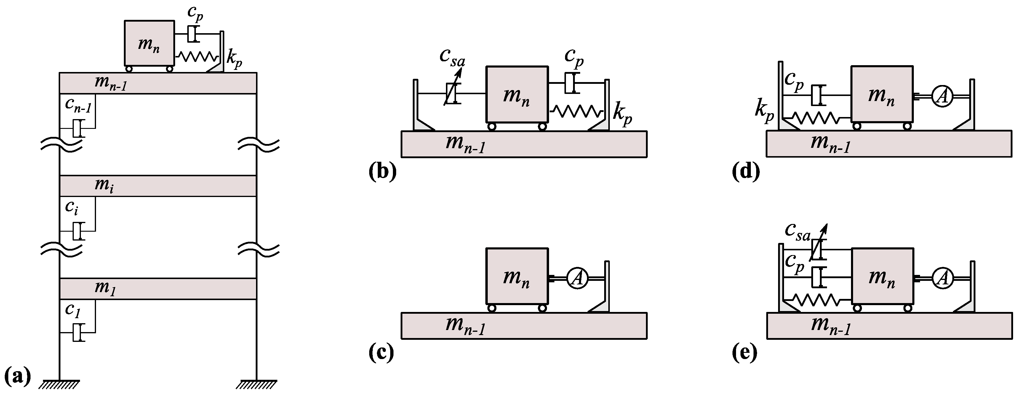
2. Modeling Principles

2.1. General Dynamic Vibration Absorbers (DVA) Modeling Approach

Modeling the novel SHMD device requires a thorough understanding of the modeling principles and procedures followed in the design of passive, active and semi-active systems. In order to do so, the dynamic behaviour of an n-DOF system coupled with a DVA (as depicted in Figure 1) under a random dynamic loading needs to be considered through its equation of motion:
M x ¨ ( t ) + C x ˙ ( t ) + K x ( t ) = B u ( t ) + D d ( t )
In Equation (1), each overdot declares single differentiation with respect to time, M , C and K are the n × n mass, damping, and stiffness matrices, respectively; x ( t ) and d ( t ) are in order of the displacement, and external force n × 1 column vectors; u ( t ) is the single scalar control force and B ( n × 1 ) and D ( n × n ) are the influence matrices assigning the control and external force contributions, respectively, to the individual degree of freedoms (DOFs). For each DOF in x ( t ) being the lateral displacement of the ith ( i = 1 , ... , n ) mass, M becomes diagonal, while for the classical viscous damping considered the damping matrix C attains a form identical to the symmetric stiffness matrix K . Without any loss of generality, the DVA is attached to the (n − 1)th DOF and its motion constitutes the nth DOF. For control implementation purposes, Equation (1) can be represented in the state space domain using a first order differential equation, such that:
z ˙ ( t ) = A z ( t ) + F u ( t ) + E d ( t )
where, z ˙ ( t ) represents the first order time-change of the states z ( t ) = [ x ( t ) x ˙ ( t ) ] T of the system, A is the system block matrix containing the system’s mass, damping, stiffness properties, F is the control force locator block matrix, and E is the external perturbation locator block matrix, such that:
A = [     0           I         M 1 K M 1 C ] , F = [ 0   M 1 B ] , E = [ 0   M 1 D ]
With I being the identity matrix of appropriate dimensions (i.e., ( n × n ) ).

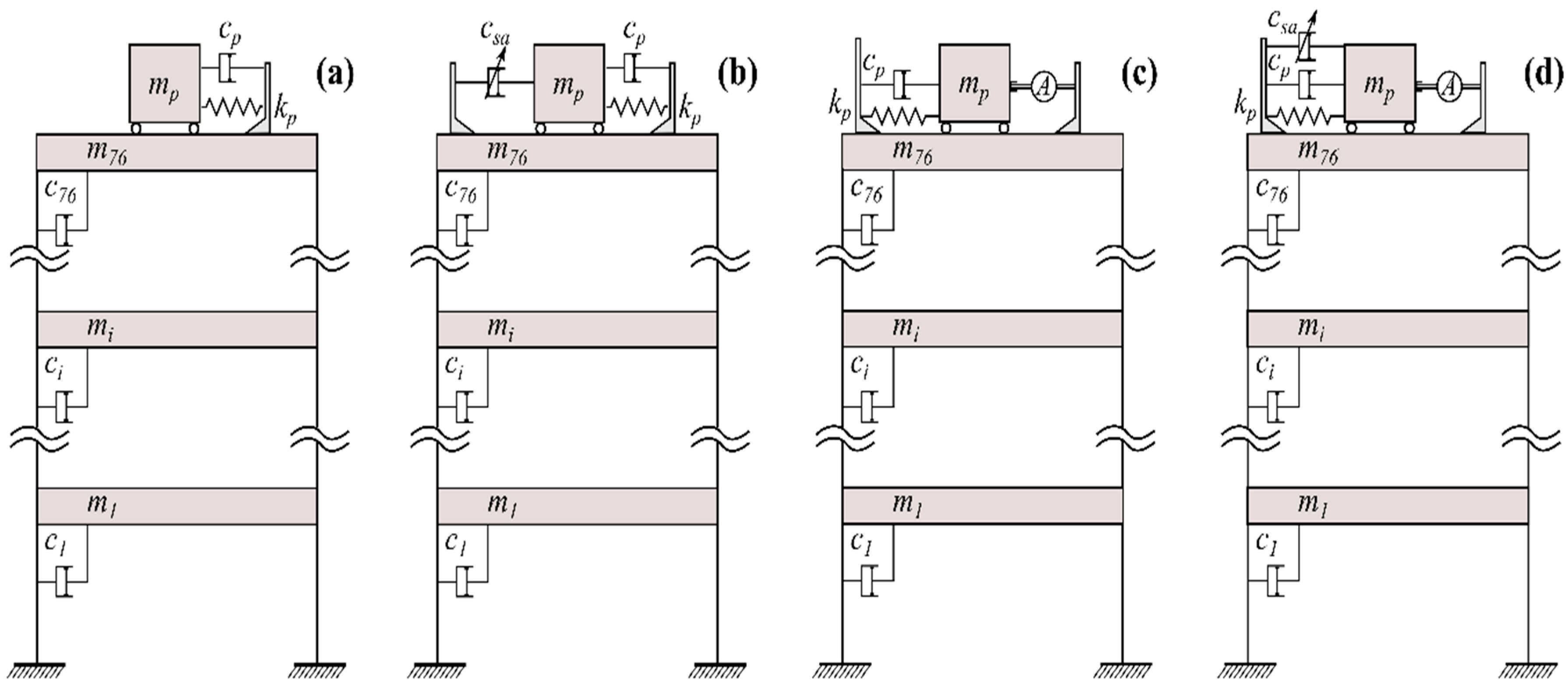
2.1.1. Passive Tuned Mass Damper (TMD) Control

A TMD device produces control actions as a result of the relative motion of its mass against the structural mass such that the control force term, u ( t ) in Equation (2) is calculated at each time step by:
u ( t ) = k p x r ( t ) + c p x ˙ r ( t )
In this equation, x ˙ r ( t ) and x r ( t ) are respectively the relative velocity and displacement between the nth and (n − 1)th DOFs and c p and k p , are the passive damping and stiffness coefficients respectively. To this date, most of the tuning of the mechanical parameters c p and k p of a TMD device is achieved via closed-form expressions derived from the minimisation of the rms acceleration response of a single degree of freedom (SDOF) subjected to white noise or harmonic excitation. While this approach is broadly accepted, representing civil engineering structures with an equivalent SDOF system can lead to significant errors in the estimation of their dynamic response. The problem amplifies when one considers the probabilistic nature of the knowledge of the system’s properties and the fact that the estimated properties can vary with time (e.g., amplitude dependence, fluid–structure interaction, etc.). Moreover, obtaining TMD mechanical parameters through the use of harmonic or flat spectrum inputs may not always yield optimum values [18]. In this paper, because the motion of long period structures is generally governed by the first modal response, the stiffness coefficient of the auxiliary device is selected just as the mass damper is tuned to the fundamental frequency of the structure, whereas the damping coefficient is obtained using the expressions found in [19,20], and validated and adjusted when necessary through numerical optimisation based on [21,22] for the case of the more complex, wind-excited multi-degree of freedom (MDOF) structural system.

2.1.2. Active Mass Damper (AMD) Control and Hybrid Active-Tuned Mass Damper (ATMD) Control

For a purely active system, the passive control force takes the form of a desired action, u a ( t ) determined via a control algorithm such as the Linear-Quadratic-Regulator (LQR), proportional-integral-derivative (PID) controller or similar. With reference to Figure 1c, for the case of AMD control, the force is delivered solely by means of mechanical actuation; thus the actuation force f a ( t ) is equal and opposite to the calculated desired action:
u a ( t ) = f a ( t )
Obviously, for the purpose of limiting the stroke and the requirement of a fail-safe mechanism, an ATMD is found in most practical applications [3,8]. To this end, and with reference to Figure 1d, for an ATMD, the desired force is mathematically expressed as the summation of the passive forces generated by the motion of the mass damper and an additional external force provided by means of mechanical actuation. Because the dynamic characteristics of the mass damper remain unaltered and the desired interaction force has been already calculated by the control algorithm, the required conventional hybrid actuation, f a _ a t m d ( t ) is determined from:
u a ( t ) = c p x ˙ r ( t ) + k p x r ( t ) f a _ a t m d ( t )
In Equation (6), the mechanical properties c p , k p of the device can be selected similarly to a purely passive device. Still, typically a higher damping coefficient c p is used along with the ATMD device for stroke-restraining purposes [3,21].

2.1.3. Semi-Active Tuned Mass Damper (STMD) Control

Similar to an active system, the semi-active counterpart makes use of control algorithms for the selection of appropriate control actions. The first step in the calculation of the semi-active control forces is the calculation of an equivalent active force using active algorithms and Equation (5). Next, the active force is tailored so that it can be physically realised by the semi-active device. In this regard, because of the fact that no energy can be added directly to the system, the semi-active device will produce control forces only when required, i.e., when the damper is requested to “consume” energy. This is achieved by applying semi-active force saturation limits such that the semi-active control force, u s a ( t ) is calculated by [23]:
u s a ( t ) = f a ( t ) ( 1 sgn [ f a ( t ) x ˙ r ( t ) ] 2 )
sgn [ f a ( t ) x ˙ r ( t ) ] = sgn ( q a ( t ) ) { 1 1 f o r f o r q a 0 q a < 0
The product of f a ( t ) x ˙ r ( t ) is the power, q a ( t ) , of the whole active system device. Similarly, the power of just the semi-active component, q s a ( t ) , is defined as the product of the force that can be physically translated by the device, u s a ( t ) , and its relative velocity, x ˙ r ( t ) :
q s a ( t ) = u s a ( t ) x ˙ r ( t ) < 0
A schematic representation of the power time histories of both an actively and a semi-actively controlled device is shown in Figure 2. It can be observed that the active device has the advantage of both adding and dissipating energy, as indicated by positive and negative powers, while the semi-active device only consumes power (indicated by only negative power—and its integral energy is also negative).
When a variable damping (VD) STMD is considered, the method of achieving enhanced performance is by appropriately and in a timely fashion adjusting the damping coefficient of the device within bands, in order for the required control force to be reached. By referring back to the system presented in Figure 1, the semi-active damping force contribution can be expressed as c s a ( t ) x ˙ r ( t ) . Inspection of Equation (9) easily leads to c s a ( t ) < 0 . Updating Equation (6), the resulting overall control force provided at each time instant by a VD-STMD can be expressed mathematically as:
u s a ( t ) = ( | c s a ( t ) | + c n ) x ˙ r ( t ) + k p x r ( t )
In Equation (10), c n is a small damping coefficient representing the inherent damping of the connection of a semi-active device and the structural system. In this equation, the time-varying semi-active damping coefficient, c s a ( t ) , is the only unknown, making the calculation of the real-time variation of the damping coefficient straightforward.

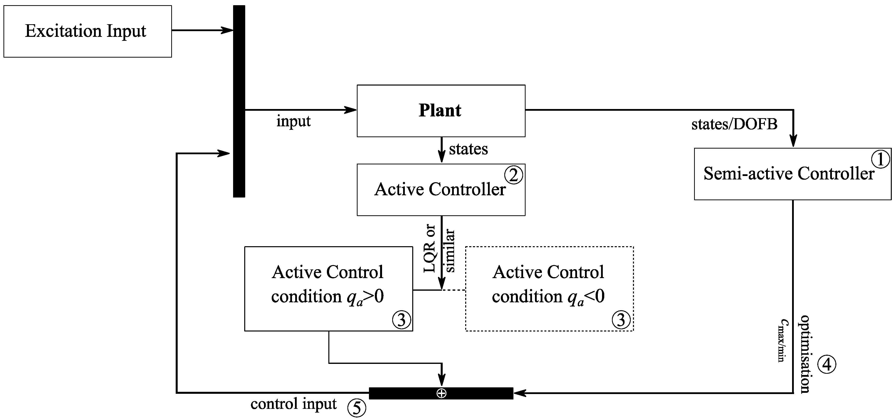
2.2. Modeling the Semi-Active Hybrid Mass Damper

Through the use of an SHMD, the energy-dissipation capacity of a semi-active device is exploited and energy is added only when required through force actuators. The main difference between an ATMD and the novel SHMD configuration lies in the fact that the actuators of the ATMD both add and dissipate energy, whereas the forcing provision of the SHMD can only add energy. To this end, it can be realised that when the actuators of the ATMD are required to add energy to the system, sufficient power should be provided so that the “braking” force acting on the DVA’s mass by the passive damping elements of the ATMD is surpassed for the mass to be accelerated, and sufficient control force can then be applied to the system. On the contrary, the novel SHMD configuration lowers the active actuation demands by lowering the semi-active damping component to its minimum value throughout the period of active actuation. The steps required for the implementation of this configuration and the calculation of the envisaged control action, u s h m d ( t ) , are explicitly introduced below and summarised in Figure 3:
(1)
Design of a semi-active controller based either on an active controller that is clipped using Equation (7) for semi-active control purposes or using direct output feedback control algorithms such as the ones found in the groundhook control scheme for alleviation of the online computational burden of Equations (7) and (8).
(2)
Design an active controller using active control algorithms such as LQR, PID or similar designed to satisfy performance and robustness specifications of the non-linear system (i.e., system including the semi-active controller).
(3)
Limit the capacity of the active actuator to only add power to the system:
q a ( t ) = f a ( t ) x ˙ r ( t ) > 0
(4)
Incorporation of both active and semi-active forces to the system using:
u s h m d ( t ) = u s a ( t ) + f a ( t )
(5)
Optimisation of maximum and minimum damping ratios of the semi-active control device for the case of on-off control.
Using the steps described, the resulting control signals relative to the active control counterpart should attain the form shown in Figure 4b,c. Evidently, the active control component of the novel device configuration (Figure 4c) can only supply force in the q a 0 regions, whereas the semi-active control component is able to only supply force in the q a 0 regions. With reference to Figure 4b, the fifth and final step of the SHMD design procedure, the optimisation of the maximum and minimum damping coefficients of the semi-active component determines the slope and the magnitude of the control signal which in turn severely influence the performance of the hybrid system.

3. Control Methods

Obtaining the semi-active and active forcing components is achieved via the use of control algorithms. In this study, for the purely active control case, the algorithm of choice is the optimal LQR that was proven suitable in a series of studies [3,24,25,26] for use on flexible structural applications. The design of the controller (i.e., the determination of the weighting matrices which are required in the determination of the control gains) is based on the performance index defined in [25]. For the case of semi-active control, the displacement based groundhook algorithm that belongs to the category of direct output feedback controllers (i.e., the control actions are calculated based on a limited number of measurements) is selected. The choice of this direct output feedback controller for the case of semi-active control is based on the reduction of the computational effort required for the online calculation of Equations (7) and (8), requirement of minimum state measurements as well as its enhanced performance over other conventional direct output feedback controllers as shown in the studies of [21,27]. The mathematical expressions describing the control algorithm used in the derivation of the control actions are found in [28,29].
With reference to Section 2.2, and because of the fact that semi-active control precedes the design of the active controller, the incorporation of semi-active control to the system results in a configuration that is no longer linear but piecewise linear, generating the need for linearisation before a purely active controller is designed. In this study, the linearisation of the piecewise linear system is performed via input/output subspace SSARX identification using MATLAB’s (MATLAB2016a, The MathWorks Inc., Natick, MA, USA, 2016) system identification toolbox. To this end, a purely harmonic signal with known frequency and amplitude is used as the external input to the system. The displacement of the structural mass was used as the output. From this, a four-state equivalent linear system is constructed and the state matrices are extracted for use in the active controller design procedure.

4. Numerical Investigation

4.1. Single Degree of Freedom (SDOF) Structural Configuration

In order to quantitatively capture the performance gains of the proposed system on both the transient and steady-state components of the vibration response, four alternatives, namely passive (TMD), semi-active (STMD), active (ATMD) and semi-active hybrid (SHMD)-equipped (low-damped) SDOF structures, are investigated. For the simulations, the mass and stiffness of the SDOF structure is selected such that the resulting mass ratio of the structural mass to the mass of the damper is 1% and the frequency of the system is approximately 1 rad/s, typical for high-rise structural applications. The resulting mass, stiffness and damping matrices used in the simulations are:
M = ( 1000 0 0 10 ) Kg K = ( 1009.9 9.9 9.9 9.9 ) Ns / m C = ( 51.22 1.22 1.22 1.22 ) Ns / m C w = ( 50.04 0.04 0.04 0.04 ) Ns / m
In Equation (13), C is the damping matrix used for the case of TMD control, and C w is the damping matrix used for the case of STMD, ATMD and SHMD control. It is evident that for the case of passive control, a damping ratio of 6.1% and stiffness tuning ratio of 0.9 derived using Den Hartog’s expressions found in [19] are used for optimal passive behaviour and maximum rms reduction at steady state. For the remaining three control cases, a minimal damping ratio of 0.2% is used in order to capture the inherent damping of the connection of the damper and the structural mass.

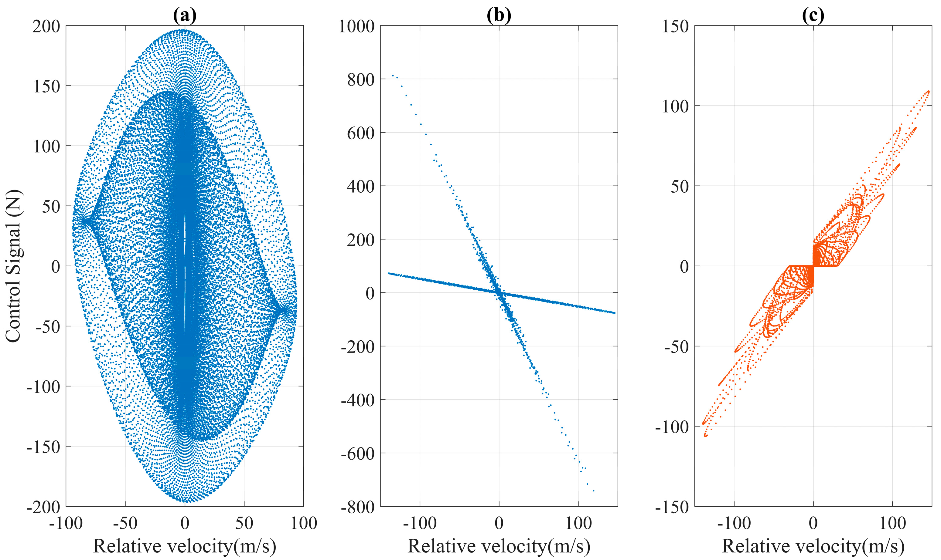
4.2. Variable Damping Coefficient Configuration

For the fairness of the comparison and consistency with the optimisation procedure followed for the case of passive TMD control, the selection of the variable damping coefficients for the case of the semi-active and hybrid controlled SDOF systems is performed via examination of the rms acceleration response of the system at steady state. To this end, an investigation of the acceleration response for maximum damping ratios ( ζ max = c max / 2 m d ω n ) ranging from 1% to 100% of the critical damping is carried out, the results of which are presented in Figure 5 and Figure 6. With reference to Figure 5a, for the STMD-equipped system, at higher damping ratios, the acceleration response of the structural mass reduces and the distance between the side lobes increases. On the contrary, for the SHMD-equipped system (Figure 5b), it can be observed that at low damping ratios, it has a performance inferior to its STMD-equipped counterpart. Nevertheless, as the damping ratios increase beyond the value of 0.3, the performance of the SHMD-equipped system drastically improves, reducing the acceleration response while at the same time pushing the side-lobes of the response further apart. The comparison of the two systems as a function of the damping ratio is shown in Figure 5c which presents the difference of the acceleration responses of the two systems (i.e., x ¨ s h m d ( ω ) x ¨ s t m d ( ω ) ). Owing to the selected sign convention, negative values in Figure 5c indicate performance gains of the SHMD over the STMD system, while positive values indicate performance loss. For clarity, the two-dimensional acceleration response of the STMD and SHMD controlled systems for maximum damping ratios of 0.3, 0.5, 0.75 and 1 is presented in Figure 6. The average response of the systems over the wider range of frequencies is captured by the area under the response curves as illustrated in the same figure.
For the case of the SDOF, the performance of the novel hybrid configuration is investigated at the average maximum damping ratio of 0.5. Similar to the passive (TMD) optimisation procedure, when practical constraints are applied such as force and stroke saturation limits (for the case of the MDOF system), further numerical optimisation is carried out and appropriate values of maximum damping coefficients are selected. For the fairness of the comparison, the SDOF the STMD configuration is also designed with a maximum damping ratio of 0.5.

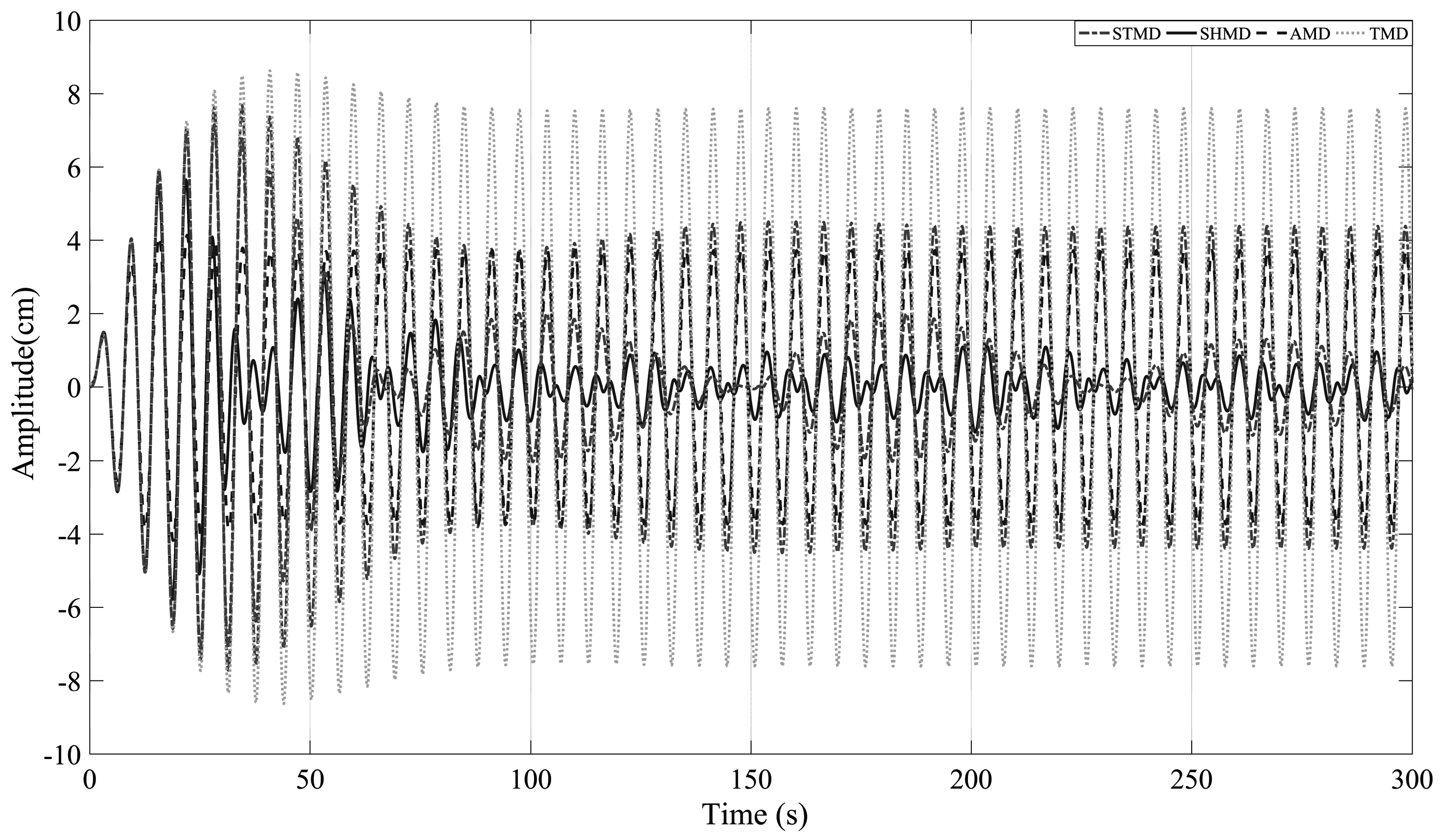
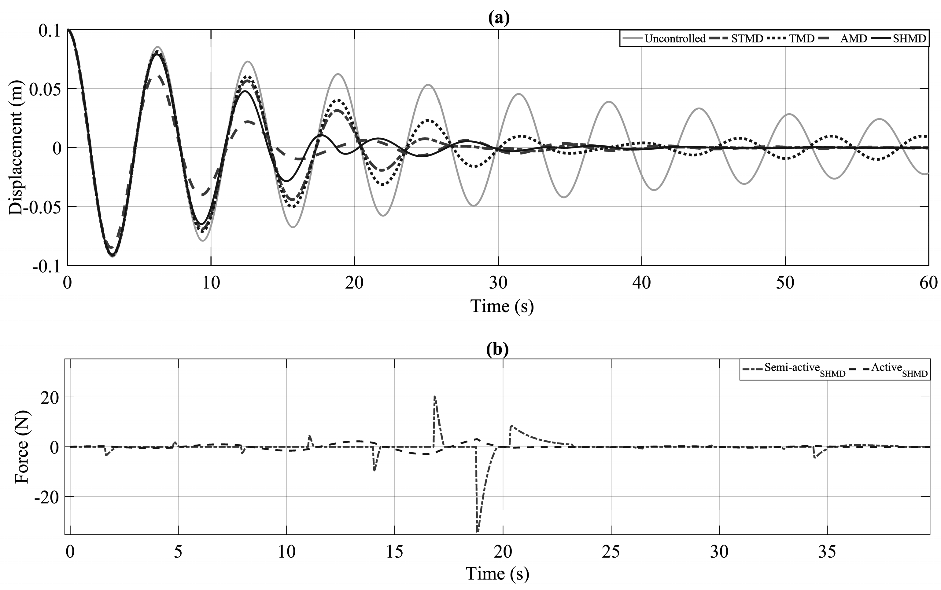
4.3. Free Vibration Analysis

For the first set of simulations, the SDOF is given an arbitrary initial displacement of 10 cm and is allowed to vibrate freely. Figure 7a,b illustrate the system’s displacement along with the active and semi-active forces required by the SHMD system.
Clearly, the rate of decay of the system’s response is a good primary indication of its effective damping. In this regard, it is shown that at the absence of a DVA, the low damped structure requires a much longer settling time. On the other hand, once a DVA is employed in the form of TMD, STMD, ATMD and SHMD the settling times drastically decrease, thereby demonstrating the effective damping of each of the five structural configurations. More specifically, out of the four DVA configurations, the SHMD and ATMD seem to be superior to their purely passive and semi-active counterparts. As a matter of fact, it is evident that the system coupled with an SHMD device follows closely the trajectory of the AMD-equipped, one particularly at the late part of the vibration response.

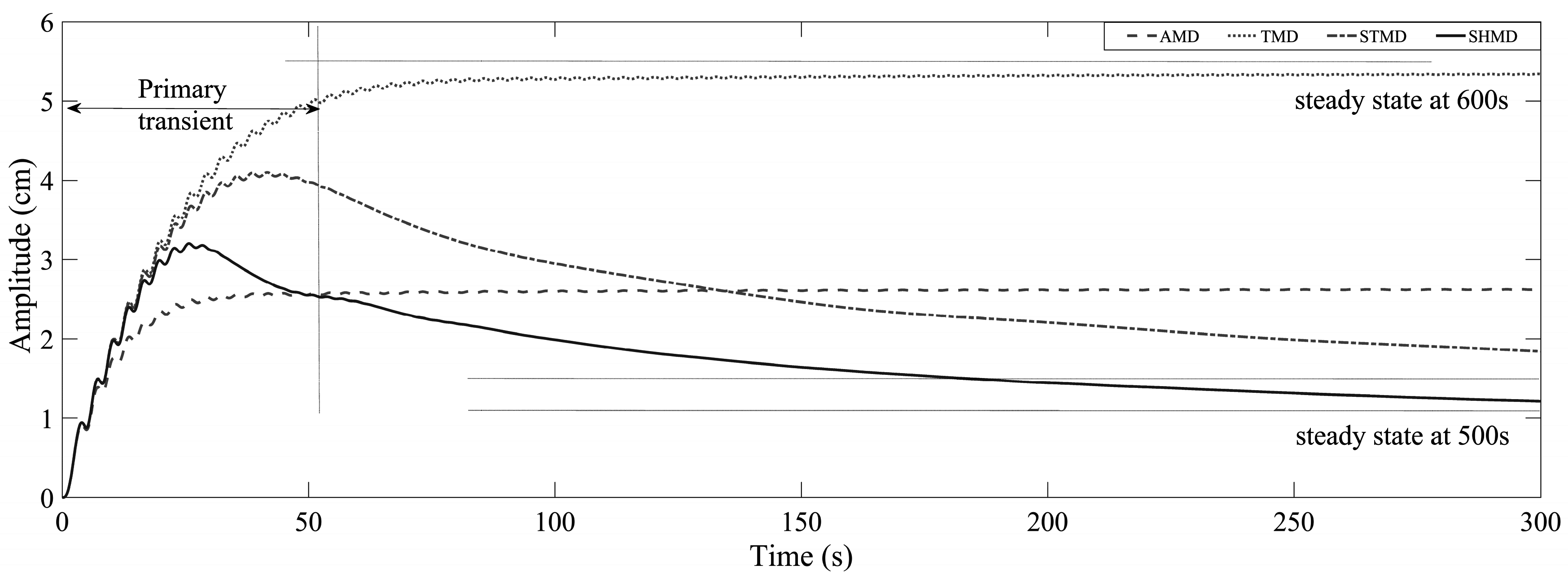
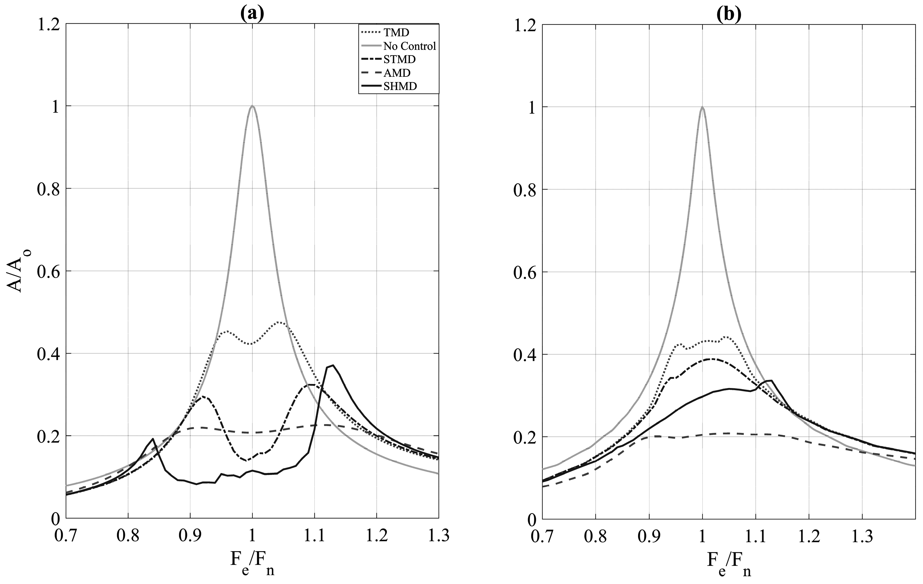
4.4. Forced Vibration

Systems equipped with devices such as STMD (and also SHMD) are no longer linear but piecewise linear. For many non-linear systems, the response magnification factor may depend on the type and magnitude of the excitation and the resulting structural response might be of random non-periodic nature. Yet, following the proof of Hac and Youn [30,31], the response of piecewise linear second-order systems to periodic excitation is also periodic, and the amplitude ratio is independent of the excitation amplitude. In other words, exciting the structure using a periodic wave of notional amplitude allows for meaningful performance information in the frequency domain. Figure 8 exhibits the time history response of the structural configurations under harmonic excitation with frequency equal to the structural frequency. For clarity, only the response time histories for the cases of STMD, ATMD and SHMD and TMD are presented. Complementing these results, Figure 9 illustrates the continuous (running) displacement rms for each of the different structural configurations.
It is evident that under resonant forced vibration, the ATMD, STMD and SHMD clearly outperform the more conventional passive TMD under both the transient and steady-state parts of the vibration. Additionally, under the transient component of the vibration, the ATMD and SHMD devices are superior to the STMD. On the other hand, under steady state, the STMD is shown to be significantly better than the ATMD configuration, achieving steady-state response closer to the system equipped with the novel SHMD configuration. Similar remarks can be made after investigating the steady-state and peak frequency response functions (the response of the system at different frequencies, shown here as the ratio of the frequency of the external perturbation, F e and the natural frequency, F n of the structure) of the systems. Figure 10a,b illustrate that the novel device configuration achieves the best compromise between steady-state and transient performance.

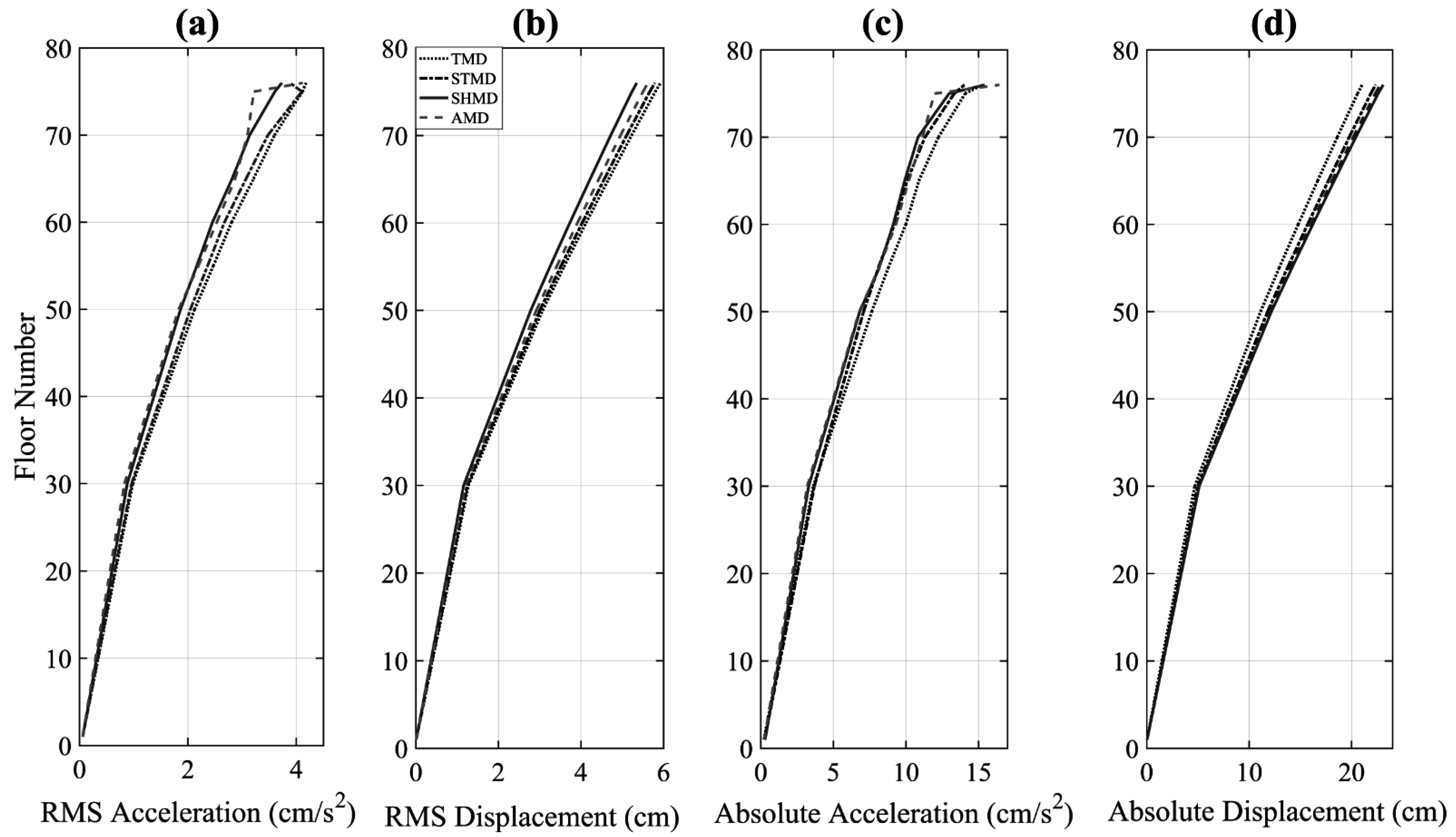
4.5. High-Rise Structural Configuration

In order to establish the robustness of the novel device and its ability to reduce wind vibration response, it is important to evaluate its performance on realistic high-order systems for which constraints such as actuator force-power demands and damper strokes can be taken into account. To achieve this, the 76-storey benchmark wind-sensitive sway structure proposed by Yang et al. [3] is used in this study. The building has a square 42 m × 42 m cross-section, with a height to width aspect ratio of 7.3 and a low natural frequency that lends it the wind sensitivity attribute. A simplified planar finite element model of the structure is constructed by considering the portion of the building between two adjacent rigid floors as a classical beam element of uniform thickness, leading to 76 rotational and 76 translational degrees of freedom. From these, all the rotational degrees of freedom have been removed using static condensation, leading to a lumped mass sway model with degrees of freedom, representing the displacement of each floor in the lateral direction. The resulting simulated structure has a total mass of 153,000 tons, with the first five frequencies at 0.16, 0.765, 1.992, 3.790 and 6.395 Hz, and corresponding modal structural damping ratios of 1% calculated using Rayleigh’s approach. In this study, four alternatives, namely: passive (TMD), semi-active (STMD), active (ATMD) and semi-active hybrid (SHMD) controlled structures are used for the establishment of the comparison metrics. The assemblage of the different control configurations is depicted in Figure 11.
In every control configuration, the dynamic absorber comprises an inertial mass of 500 tons that corresponds to 0.356% of the total structural mass, limited by realistic structural design constraints. For DVA configurations that require tuning of the device (i.e., TMD, SHMD and STMD), appropriate spring stiffness, k p , is chosen such that the device is tuned to the fundamental frequency of the structure (i.e., ≈ 0.16 Hz).
In order to ensure the fairness of the comparison, it was deemed necessary to restrain the maximum damper stroke of each of the alternatives by increasing the damping coefficient of the device appropriately so as to limit strokes to a maximum of 95 cm. Because control configurations that damper strokes are not a cause of concern, such as the case of the TMD, the damping ratio is numerically optimised (and kept low, approximately to the value calculated using Den Hartog’s equations [19]) for maximum rms acceleration response reduction. The resulting damping coefficients that equalise the maximum strokes at maximum rms acceleration response reduction are outlined in Table 1 below:

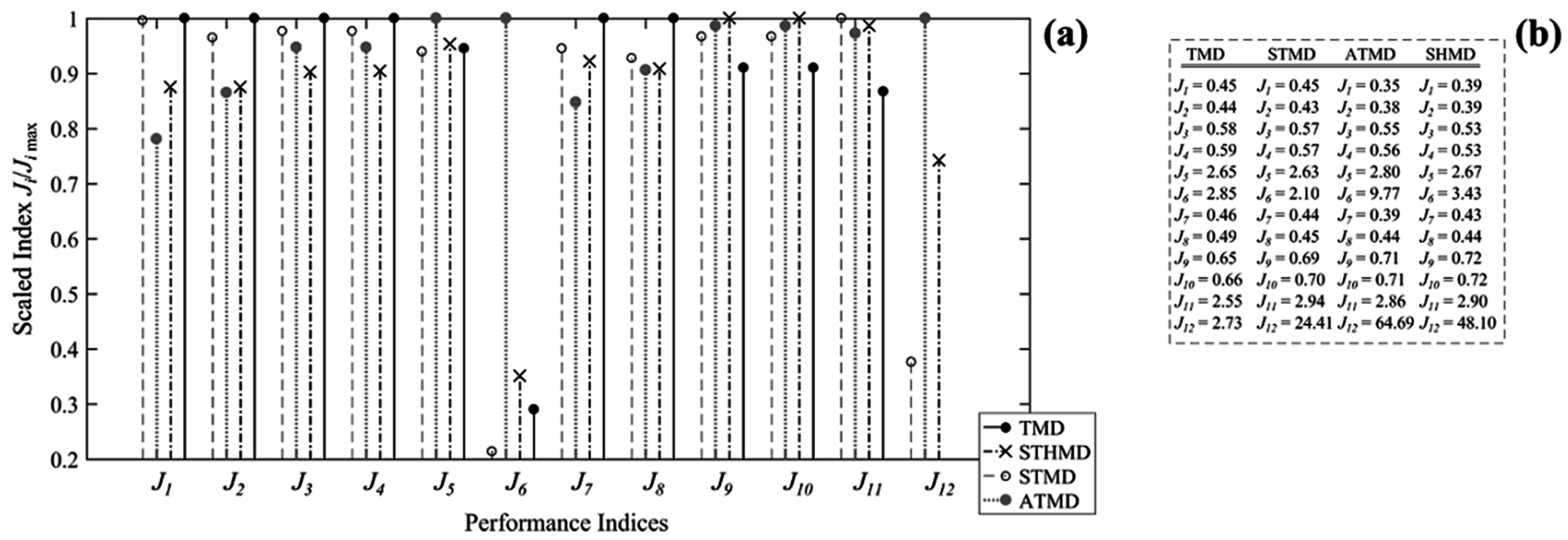
4.6. Evaluation Criteria

The comparison of the different control strategies is based on the stationary response properties of the different control structures. From the response time histories, the rms and peak accelerations and displacements at different storeys were obtained. From the obtained values, 12 performance criteria were identified. The first criterion, J 1 , appraises the ability of the control strategy to reduce rms accelerations:
J 1 = max ( σ x ¨ 1 , σ x ¨ 30 , σ x ¨ 50 , σ x ¨ 55 , σ x ¨ 60 , σ x ¨ 65 , σ x ¨ 70 , σ x ¨ 75 ) / σ x ¨ 75 o
where σ x ¨ i is the rms acceleration of the ith storey and σ x ¨ 75 o is the rms acceleration of the 75th floor (last occupied floor) without control. The second performance criterion evaluates the average performance of six floors above the 49th floor:
J 2 = 1 6 ( σ x ¨ i / σ x ¨ i o )
For i = 50 , 55 , 60 , 65 , 70 , 75 ; where, σ x ¨ i o is the rms of the ith floor without control. The third and fourth performance indices assess the ability of the control system to reduce top floor displacements:
J 3 = σ x 76 / σ x 76 o
J 4 = 1 7 i ( σ x i / σ x i o )
For i = 50 , 55 , 60 , 65 , 70 , 75 , 76 ; where, σ x i is the rms displacement of the ith floor, σ x i o is the rms displacement of the ith storey without control and σ x 76 o is 10.136 cm. The fifth and sixth indices take into account the rms stroke of the damper (i.e., i = 77) and the average power respectively:
J 5 = σ x 77 / σ x 76 o
J 6 = { 1 T 0 T [ x ˙ 77 ( t ) u ( t ) ] 2 d t } 1 / 2
In which, σ x 77 is the rms stroke of the damper, x ˙ 77 ( t ) is the damper velocity and T is the total time of integration. Similarly to the first performance indices, the next four criteria (i.e., J 7 to J 10 ) evaluate the performance in terms of peak response quantities:
J 7 = max ( x ¨ p 1 , x ¨ p 30 , x ¨ p 50 , x ¨ p 55 , x ¨ p 60 , x ¨ p 65 , x ¨ p 70 , x ¨ p 75 ) / x ¨ p 75 o
J 8 = 1 6 i ( x ¨ p i / x ¨ p i o )
For i = 50 , 55 , 60 , 65 , 70 , 75 ;
J 9 = x p 76 / x p 76 o
J 10 = 1 7 i ( x p i / x p i o )
For i = 50 , 55 , 60 , 65 , 70 , 75 , 76 ; where, x ¨ p i is the peak acceleration of the ith floor with control and x ¨ p i o is the peak acceleration of the ith floor without control. Similarly, x p i is the peak displacement of the ith floor and x p i o is the peak displacement of the ith floor without control and x p 76 o = 32.3 cm. The 11th criterion assesses the ability of the control strategy to minimise the stroke of the damper:
J 11 = x p 77 / x p 76 o
In which x p 77 is the peak stroke of the actuator. The last criterion examines the control effort by calculating the maximum required power by:
J 12 = max | x ˙ 77 ( t ) u ( t ) |
From the above-defined criteria, it can be observed that the better the performance, the smaller the performance indices J 1 , J 2 , .. , J 12 [3].

5. Simulation Results and Discussion

Four structural configurations consisting of passive, semi-active, hybrid active and semi-active hybrid control devices were considered for investigating the efficacy of the SHMD device for the vibration control of high-rise structures. Figure 12 summarises the peak and rms (displacement and acceleration) responses at every floor. The results of the evaluation for the different performance criteria J 1 , J 2 , .. , J 12 are presented in Figure 13.
The results indicate that, for approximately the same damper strokes, the SHMD-equipped structure is able to achieve similar performance as the ATMD-equipped one, while clearly outperforming the passive and semi-actively controlled alternative. With reference to Figure 13 and Figure 14, it is evident that the SHMD device requires much less energy and actuation demands for achieving the aforementioned performance increase. As a matter of fact, the SHMD device requires approximately 26% of the total energy required by the ATMD device (1245 kJ compared to 4863 kJ). This is due to the large control effort and consequently the large amount of energy required to be added by the active actuators (approximately 4125 kJ or 82% of the total required active energy) in order to effectively accelerate the mass so that sufficient control force is provided in order to overcome the “braking” force acted by the passive component of the ATMD. Conversely, in the SHMD configuration, while the actuators are accelerating the mass, the semi-active damping component attains its minimum value, minimising the “braking” force needed to be counteracted by the actuators, thus requiring a lower control power (Figure 14b top). The energy required to be added in the SHMD configured structure is only 1245 kJ compared to 4125 kJ (which accounts for the 82% of the total energy required) (Figure 14). On the other hand, for energy dissipation purposes (Figure 14a,b bottom), the ATMD configuration is required to supply only a fraction (737 kJ and the remaining 18% of the total energy) of energy, while the SHMD-equipped structure requires consumption of a staggering 4600 kJ. However, since energy dissipation in the SHMD configuration occurs exclusively in the semi-active elements, the required energy depends solely on the selected semi-active device. Still, regardless of the device, the energy required for semi-active control is not expected to exceed the order of a few watts [32].
For more tolerant damper stroke limits, a lower passive damping ratio can be chosen for the ATMD which will reasonably lower the actuation demands for energy addition. On the contrary, lower damping ratios of the damping device will require the actuators to work harder in dissipating energy by decelerating the mass (and essentially work as an energy-expensive passive damper). The aforementioned arguments are illustrated in Figure 15, in which the power required by a purely active AMD device (i.e., absence of passive damping component) is investigated. As can be observed, the AMD is required to expend most of its energy for dissipation (4500 kJ as opposed to the 720 kJ required by the ATMD counterpart), while only a small fraction of that energy is required for energy addition (approximately 1100 kJ). It should be clarified that no further comparisons can be made with the purely active AMD system, as its performance is theoretically uncapped (the larger the control effort, the lower the response).

6. Conclusions

In this study, a novel hybrid control device configuration termed semi-hybrid mass damper (SHMD) has been proposed as an alternative design to the traditional hybrid active-tuned mass damper (ATMD) for vibration suppression of dynamic structural systems. The fundamental novelty of this configuration is that it enables modulation of the instantaneous effective system damping via the successive and appropriate action of active and semi-active elements. For this case, the active components of the SHMD device are regulated by an optimal Linear-Quadratic-Regulator (LQR) controller, while the semi-active components are controlled via a direct output feedback displacement based groundhook (DBG) controller. A numerical step-by-step procedure for the calculation of the control actions and the coupling of the devices has been proposed in this paper. Under vibration analyses run on both single degree of freedom (SDOF) and multi-degree of freedom (MDOF) SHMD configured structures, it is shown that the device is effective in reducing both the steady-state, as well as the peak frequency responses of the structural system, achieving similar performance gains to that of an ATMD-equipped structure. However, its achievement is not only the use of this novel hybrid mass damper configuration as a vehicle for enhancing vibration attenuation performance or providing a fail-safe mechanism, it is also shown that the successive action of active and semi-active elements allows an improvement in efficiency both in terms of power and actuation demands. By providing a feasible, reliable, effective and efficient alternative structural control approach, this novel hybrid configuration allows the concept of active control of structures to be extended to one of “active” structures for which both active and semi-active components are integrated and simultaneously optimised to produce a new breed of slenderer, longer and taller structures and structural forms.

Acknowledgments

The authors gratefully acknowledge EPSRC UK (Grant No. EP/L504993/1) and the University of Leeds for the financial support to this study.

Author Contributions

This work constitutes part of the doctoral dissertation of the first author who prepared the manuscript and practiced all the analytical work. The second author supervised, reviewed and edited the work where appropriate.

Conflicts of Interest

The authors declare no conflict of interest.

References

  1. Holmes, D.J. Wind Loading of Structures; CRC Press: Sound Parkway NW, FL, USA, 2007. [Google Scholar]
  2. Ricciardelli, F.; Pizzimenti, A.D.; Mattei, M. Passive and active mass damper control of the response of tall buildings to wind gustiness. Eng. Struct. 2003, 25, 1199–1209. [Google Scholar] [CrossRef]
  3. Yang, N.Y.; Agrawal, A.K.; Samali, B.; Wu, J.C. Benchmark Problem for Response Control of Wind-Excited Tall Buildings. J. Eng. Mech. 2004, 130, 437–446. [Google Scholar] [CrossRef]
  4. Zhang, Y.; Li, L.; Cheng, B.; Zhang, X. An active mass damper using rotating actuator for structural vibration control. Adv. Mech. Eng. 2016, 8. [Google Scholar] [CrossRef]
  5. Haertling, G. Rainbow ceramics: A new type of ultra-high displacement actuator. Am. Ceram. Soc. Bull. 1994, 73, 93–96. [Google Scholar]
  6. Scruggs, J.; Iwan, W. Control of a civil structure using an electric machine with semiactive capability. J. Struct. Eng. 2003, 129, 951–959. [Google Scholar] [CrossRef]
  7. Zhang, C.; Ou, J. Modeling and dynamical performance of the electromagnetic mass driver system for structural vibration. Eng. Struct. 2015, 82, 93–103. [Google Scholar] [CrossRef]
  8. Ikeda, Y. Active and semi-active vibration control of buildings in Japan—Practical applications and verification. Struct. Control Health Monit. 2009, 16, 703–723. [Google Scholar] [CrossRef]
  9. Fujinami, T.; Saito, Y.; Masayuki, M.; Koike, Y.; Tanida, K. A hybrid mass damper system controlled by Hinfity control theory for reducing bending-torsion vibration of an actual building. Earthq. Eng. Struct. Dyn. 2001, 30, 1639–1643. [Google Scholar] [CrossRef]
  10. Nakamura, Y.; Tanaka, K.; Nakayama, M.; Fujita, T. Hybrid mass dampers using two types of electric servomotors:AC servomotors and linear-induction servomotors. Earthq. Eng. Struct. Dyn. 2001, 30, 1719–1743. [Google Scholar] [CrossRef]
  11. Watakabe, M.; Tohdp, M.; Chiba, O.; Izumi, N.; Ebisawa, H.; Fujita, T. Response control performance of a hybrid mass damper applied to a tall building. Earthq. Eng. Struct. Dyn. 2001, 30, 1655–1676. [Google Scholar] [CrossRef]
  12. Mitchel, R.; Kim, Y.; El-Khorchi, T. Wavelet neuro-fuzzy control of hybrid building-active tuned mass damper system under seismic excitations. J. Vib. Control 2012. [Google Scholar] [CrossRef]
  13. Tan, P.; Liu, Y.; Zhou, F.; Teng, J. Hybrid Mass Dampers for Canton Tower. CTBUH J. 2012, 24–29. [Google Scholar]
  14. Li, C.; Cao, B. Hybrid active tuned mass dampers for structures under the ground acceleration. Struct. Control Health Monit. 2015, 22, 757–773. [Google Scholar] [CrossRef]
  15. Tso, M.H.; Yuan, J.; Wong, W.O. Hybrid vibration absorber with detached design for global vibration control. J. Vib. Control. 2016. [Google Scholar] [CrossRef]
  16. Khan, I.U.; Wagg, D.; Sims, N.D. Improving the vibration suppression capabilities of a magneto-rheological damper using hybrid active and semi-active control. Smart Mater. Struct. 2016, 25, 085045. [Google Scholar] [CrossRef]
  17. Demetriou, D.; Nikitas, N.; Tsavdaridis, K.D. A Novel Hybrid Semi-active Tuned Mass Damper for Lightweight Steel Structural Applications. In Proceedings of the IJSSD Symposium on Progress in Structural Stability and Dynamics, Lisbon, Portugal, 21–24 July 2015.
  18. Ricciardelli, F.; Occhiuzzi, A.; Clemente, P. Semi-active tuned mass damper control strategy for wind-excited structures. J. Wind Eng. Ind. Aerodyn. 2000, 88, 57–74. [Google Scholar] [CrossRef]
  19. Hartog, D. Mechanical Vibrations; McGraw-Hill Book Company: New York, NY, USA, 1956. [Google Scholar]
  20. Ghosh, A.; Basu, B. A closed-form optimal tuning criterion for TMD in damped structures. Struct. Control Health Monit. 2007, 14, 681–692. [Google Scholar] [CrossRef]
  21. Demetriou, D.; Nikitas, N.; Tsavdaridis, K.D. Performance of fixed-parameter control algorithms on high-rise structures equipped with semi-active tuned mass dampers. Struct. Des. Tall Spec. Build. 2016, 25, 340–354. [Google Scholar] [CrossRef]
  22. Nelder, J.; Mead, R. A simplex method for function minimization. Comput. J. 1965, 7, 308–313. [Google Scholar] [CrossRef]
  23. Hrovat, D.; Barak, P.; Rabins, M. Semi-Active Versus Passive or Active Tuned Mass Dampers for Structural Control. J. Eng. Mech. 1983, 109, 691–705. [Google Scholar] [CrossRef]
  24. Yang, N.J.; Akbarpour, A.; Ghaemmaghami, P. New Optimal Control Algorithms for Structural Control. J. Eng. Mech. 1987, 113, 1369–1386. [Google Scholar] [CrossRef]
  25. Soong, T.T. Active Structural Control: Theory and Practice; John Wiley & Sons, Inc.: New York, NY, USA, 1990. [Google Scholar]
  26. Cheng, F.Y.; Jiang, H.; Lou, K. Smart Structures: Innovative Systems for Seismic Response Control; Taylor & Francis Group: New York, NY, USA, 2008. [Google Scholar]
  27. Viet, L.D.; Nghi, N.B.; Hieu, N.N.; Hung, D.T.; Linh, N.N.; Hung, L.X. On a combination of ground-hook controllers for semi-active tuned mass dampers. J. Mech. Sci. Technol. 2014, 28, 2059–2064. [Google Scholar] [CrossRef]
  28. Koo, J.H. Using Magneto-Rheological Dampers in Semiactive Tuned Vibration Absorbers to Control Structural Vibrations; Virginia Polytechnic Institute and State University: Blacksburg, VA, USA, 2003. [Google Scholar]
  29. Koo, J.H.; Murray, T.M.; Setareh, M. In search of suitable control methods for semi-active tuned vibration absorbers. J. Vib. Control 2004, 10, 163–174. [Google Scholar] [CrossRef]
  30. Hac, A.; Youn, I. Optimal semi-active suspension with preview based on a quarter car model. J. Acoust. Vib. 1992, 114, 84–92. [Google Scholar] [CrossRef]
  31. Pinkaew, T.; Fujino, Y. Effectiveness of semi-active tuned mass dampers under harmonic excitation. Eng. Struct. 2001, 23, 850–856. [Google Scholar] [CrossRef]
  32. Nagarajaiah, S.; Varadarajan, N. Short time Fourier transform algorithm for wind response control of buildings with variable stiffness TMD. Eng. Struct. 2005, 27, 431–441. [Google Scholar] [CrossRef]
Figure 1. Structural configuration and mathematical models for (a) tuned mass damper (TMD); (b) semi-active tuned mass damper (STMD); (c) active mass damper (AMD); (d) active-tuned mass damper (ATMD); and (e) semi-active hybrid mass damper (SHMD) systems.
Applsci 06 00397 g001
Figure 2. Indicative example of the “power” scheme/demand practised in (a) active; and (b) semi-active control.
Applsci 06 00397 g002
Figure 3. A schematic representation of the procedure followed for modeling the semi-active hybrid mass damper.
Applsci 06 00397 g003
Figure 4. Control signals as a function of relative velocity for the (a) purely active system; (b) semi-active component; and (c) active component of the hybrid configuration subjected to a white noise excitation.
Applsci 06 00397 g004
Figure 5. Acceleration response of (a) STMD; and (b) SHMD; and their (c) difference at different damping ratios. (Units of acceleration response in m 2 / s 3 / rad ).
Applsci 06 00397 g005
Figure 6. Acceleration response at steady state for damping ratios of (a) 0.3; (b) 0.5; (c) 0.75; and (d) 1. Shaded area illustrates average system response.
Applsci 06 00397 g006
Figure 7. (a) Displacement response time history of different control configurations; (b) control signal of active component and semi-active component of the hybrid configuration.
Applsci 06 00397 g007
Figure 8. Transient and steady-state response of the different control device configuration under harmonic loading at tuning frequency (excitation frequency 1 rad/s).
Applsci 06 00397 g008
Figure 9. Transient and steady-state Crms response of the different control device configuration under harmonic loading at tuning frequency (excitation frequency 1 rad/s).
Applsci 06 00397 g009
Figure 10. (a) Steady-state; and (b) Peak frequency acceleration response of the different structural configurations.
Applsci 06 00397 g010
Figure 11. Ensemble of all the different control options (a) TMD; (b) STMD; (c) ATMD; (d) SHMD studied herein for the model 76-storey structure of Yang et al. [3].
Applsci 06 00397 g011
Figure 12. Illustration of the performance of different control measures in terms of (a) RMS acceleration; (b) RMS displacement; (c) absolute acceleration; and (d) absolute displacement at different floor levels.
Applsci 06 00397 g012
Figure 13. (a) Normalised; and (b) non-normalised performance indices (lower index indicates better performance).
Applsci 06 00397 g013
Figure 14. Power and its time integral (dotted line) energy for (a) ATMD; and (b) SHMD configuration. Positive stands for energy addition and negative for energy dissipation.
Applsci 06 00397 g014
Figure 15. Power and its time integral (dotted line) energy of a purely active mass damper (AMD) system (no passive damping component) along with the corresponding performance indices. Positive stands for energy addition and negative for energy dissipation.
Applsci 06 00397 g015
Table 1. Damping coefficients. For clarity i) TMD, ii) STMD, iii) ATMD, iv) SHMD stand for i) tuned, ii) semi-active tuned, iii) active-tuned and iv) semi-active hybrid mass damper.
Control StrategyMax Damping Coefficient (kNs/m)Min Damping Coefficient (kNs/m)Equivalent Damping Ratio
TMD47474.7%
STMD163.42.6116%–2.6%
ATMD10010010%
SHMD1683916.8%–4%

