Review

Assessing the Dynamic Performance of Microbots in Complex Fluid Flows

by
Laura Campo-Deaño
CEFT, Faculdade de Engenharia da Universidade do Porto, Dr. Roberto Frias s/n, Porto 4200-465, Portugal
Appl. Sci. 2016, 6(12), 410; https://doi.org/10.3390/app6120410
Submission received: 29 September 2016 / Revised: 28 November 2016 / Accepted: 29 November 2016 / Published: 7 December 2016
(This article belongs to the Special Issue Applications of Complex Fluids)

Abstract

:
The use of microbots in biomedicine is a powerful tool that has been an object of study in the last few years. In the special case of using these microdevices in the human circulatory system to remove clots or to deliver drugs, the complex nature of blood flow must be taken into account for their proper design. The dynamic performance, defined in this context as the quantification of the disturbance of the flow around an object (which is essentially dependent on the microbot morphology and the rheological characteristics of the fluid) should be improved in order to diminish the damage inside the patient body and to increase the efficiency when they swim through the main veins or arteries. In this article, different experimental techniques (micro-Particle Image Velocimetry, flow visualization, pressure drop measurements, etc.) are analyzed to assess their dynamic performance when they swim through the human body immersed in complex fluid flows. This article provides a useful guide for the characterization of the dynamic performance of microbots and also highlights the necessity to consider the viscoelastic character of blood in their design.

1. Introduction

It is very common to find many examples of complex fluids in our daily lives. From food, health care products or materials for construction to human biofluids. These complex fluids are characterized by their intermediate behavior between a solid and a liquid. In the special case of the human biofluids, blood is a clear example of a complex fluid whose behavior is given by a complex mixture of its components: red blood cells, platelets, white blood cells and other elements in plasma [1,2]. The red blood cells are the most abundant component and also responsible for the rheological behavior of whole blood. When the blood is at rest for several seconds, the red cells begin to form rouleaux, leading to an interconnected network extending throughout the blood, thus increasing its resistance to deformation and imparting also an elastic response to blood. These rouleaux could be broken up by imposed shearing causing a relative decrease in the viscosity, and, therefore, a shear-thinning behaviour [1,2,3,4,5]. Another characteristic of this complex behavior is the viscoelasticity given by the relaxation time, which measures the time taken by the internal fluid structures to relax internal stresses imposed by the flow [6].
At the microscale, flows of viscoelastic fluids can be significantly different from those of their Newtonian counterparts. The most common dimensionless numbers that characterize these kinds of viscoelastic fluid flows are the Reynolds number (Re), defined as the ratio between inertial and viscous forces, Re = ρ V L / η , and the Weissenberg number (Wi), which is the ratio between elastic and viscous forces, Wi = λ V / L [7]. V represents the average velocity, L the characteristic length-scale and ρ, λ and η are the density, relaxation time and viscosity of the fluid, respectively.
Viscoelastic fluids are of great importance in some nanotechnological applications, for instance, a complete rheological characterization and understanding of the flow behavior of these fluids is crucial for the assessment of the movement of microbots immersed in complex fluids.
One of the most impressive inventions of nanotechnology is the creation of nanobots and microbots, which are mechanical or electromechanical devices that are able to perform specific functions at the nano- and micro-scale, respectively [8]. Nanobots (artificial machines sized down below 10 microns) have become very popular, although nobody has yet built artificial non-biological nanorobots, and they remain a hypothetical concept. However, microbots (sized between 10 and 1000 microns) are a reality [9] and they can be considered as "training wheels" for nanotechnology. Microbots have been developed for several purposes like industrial applications or biomedicine [10,11]. The area of biomedicine is currently one of the most challenging and offers a huge number of potential applications for the microbots to perform precise and delicate tasks inside the human body, i.e., providing a mobile viewing platform enhancing a surgeon’s view, or for protecting and treating the human body against pathogens. Microbots can provide a new method for unblocking blood clots, performing eye surgery and delivering drugs [12,13,14]. This latter application is especially interesting for the case of treatments to fight cancer, offering an alternative to the traditional chemotherapy, increasing its effectiveness while diminishing side-effects.
In this field, some research has been directed to the fabrication method of the microbot prototypes [15,16], to their control and propulsion [17,18,19,20,21,22], and to the study of their communication mechanisms [23,24,25]. It is well known that at a low-Reynolds number regime, non-reciprocal motion is required for a self-propelling device. Taylor [26] proposed that traveling waves propagating along a tail was the mechanism by which spermatozoa propel themselves. Later on, Berg and Anderson [27] discovered that some bacteria, such as E. coli, swim at Reynolds numbers as low as 10 4 by rotating their helical-shaped flagella. The various propulsion mechanisms of micro-organisms have inspired a number of magnetic microrobot designs. Inspired by the design of bacterial flagella, helical swimming microrobots with comparable dimensions to their natural counterparts have been recently developed in Nelson’s group at ETH Zurich Country. Abbott et al. [20] compared different swimming methods commonly used in literature utilizing magnetic fields, and they concluded that helical propellers are likely the best overall choice for in vivo applications; Peyer et al. [15,28] extensively reviewed the swimming mechanism of bacteria to model their motion and to fabricate artificial bacterial microbots. Moreover, they analyzed the movement of microbots through the eye monitored by an external microscope [13].
Other works developed at Antoine Ferreira’s group in France have been directed to investigating the design of magnetic microbots to be released from a catheter in the arterial system. These microbots are formed by aggregation of therapeutic magnetic microcarriers, and they studied the evolution of their shape during navigation [29]. In addition, they proposed an automated technique based on image processing and control algorithms for path finding, reconstruction and navigation control of a ferromagnetic microrobot using an MRI (Magnetic Resonance Imaging) system [21]. Peer Fischer and his co-workers analyzed the trajectories of scallop flowing through viscoelastic biofluids [30] and also the propulsion mechanisms of optimal chiral structures [31]. Venugopalan et al. [32] developed a system of magnetic nano voyagers that can be actuated in human blood at negligible dilutions. Schamel et al. [33] reported the fabrication of the smallest magnetically actuated helical propellers in complex viscoelastic media. Other investigations were focused on the computational fluid dynamics analyzing the flow due to the motion of microbots inside fluid-filled channels akin to bodily conduits with special emphasis on the effects of the radial position of the robot but only considering Newtonian fluids [34,35].
In spite of all the advances in the development of microbots for their use in biomedicine, studies about the influence of microbot morphology in the flow dynamics of viscoelastic biofluids are yet an unexplored territory demanding further investigations. In this paper, the applicability and classification of microbots is reviewed; however, most of this review paper is focused on the improving of their dynamic performance when they swim through the human circulatory system by the discussion of different experimental techniques.

2. Microbots

2.1. Applicability

Microbots have been developed in the last decade of the 20th century. They were conceived for several purposes and their range of applicability is huge starting from planetary exploration, information security systems to smart manufacturing or biomedical applications. The most promising utility is in this latter area, and, therefore, this work will be focused mainly on the development of microbots for biomedical applications.

2.2. Classification

The classification of microbots is not straightforward, and, for simplification, it can be made based on their fabrication and/or propulsion method. In this sense, most of the microbots can be sorted in one of the following categories.
  • Electrostatic microbots
    As it is well known, an electric field, which is created by an electric charge, applies a force to any other charged particles. Coulomb’s law states that the electrical force between two charged objects is directly proportional to the product of the quantity of charge on the objects and inversely proportional to the square of the separation distance between the two objects. This is the principle on which some Micro Electromechanical Systems (MEMS) are based for their control and propulsion. Specifically, electrostatic actuators have been highly explored to convert electrical energy into mechanical deformation for the propulsion of microbots [36]. For instance, Donald et al. [37] designed and fabricated MEMS microbots with an untethered scratch drive actuator used for their propulsion in order to allow the microbot to move freely without wires and rails. Other work carried out by Graule et al. [38] used electrostatic adhesion to perform robotic insets able to perch and take off.
  • Magnetic microbots
    A magnetic field is the magnetic effect of electric currents and magnetic materials. Magnetic fields have been used to apply forces and torques on magnetic microrobots, providing a valuable actuation method. The controlled magnetic fields can be generated in a variety of ways, and Nelson et al. [9] published a review article in which they detailed the power and locomotion of different microbots with special attention to magnetic microbots. Several works have been developed in this area. Pawashe et al. [39] reported the control of multiple robots by an array of electrostatic anchoring pads on the surface using also some fixed microbots to prevent translation. Later on, Mahoney and Abbott [40] demonstrated magnetic three-degree-of-freedom closed-loop position and two degree-of-freedom open-loop orientation control of a capsule used for endoscopy with a single permanent magnet. Diller et al. [41] achieved the control of multiple microbots in 3D using magnetic gradient. More recently, Diller et al. [42] proposed a theoretical framework and design for six degree-of-freedom actuation of a magnetic micro robot, and Floyd et al. [43] developed methods for controlling multiple untethered magnetic micro-robots.
  • Optically actuated microbots
    It is very common to use optical tweezers to trap particles at the scale of nanometers, and, therefore, this technique has also been being used as an actuator in microbots. However, several issues are limiting its applicability as they are low force generated, and a high aperture lens is needed to focus the laser, allowing only a very small workspace and the unsuitability for its use in vitro and in vivo [44]. Hu et al. [45] developed microrobot actuation and control using optically induced thermocapillary effects. The thermocapillary effect has been used to manipulate gas bubbles in oil using optically induced heating. Lozano et al. [46] demonstrated experimentally the orientational response and phototactic motion of spherical active colloids in an inhomogeneous laser field. Palagi et al. [47] reported that soft microrobots consisting of photoactive liquid-crystal elastomers can be driven by structured monochromatic light to carry out specific motions.
  • Catalytic microbots
    The idea of catalytic microbots is to mimic the biological motors able to convert chemical into mechanical energy [18]. Sanchez et al. [48] reported the use of catalytic microbots able to transport cells in a controllable manner and their delivery on desired targets. Moreover, Srivastava et al. [49] successfully used catalytic micro motors for the degradation of nitroaromatic pollutants in water, and other authors such as Dey et al. [50] described the pH taxis of a microbot self-propelled in the presence of an external pH gradient.
  • Bio-hybrid microbots
    These kinds of microbots are typically designed to be propelled by bacterial cells by integrating these biological cells into synthetic components [51,52]. On the other hand, these bio-hybrid microbots can also be designed by adding microhelices to artificially motorize biological cells, as, for example, sperm cells [53].

3. Complex Fluids in the Human Body for Blood Flow

The elastic properties of some human fluids like blood, saliva or vitreous humor plays an important role in their flow behavior. As it was mentioned previously, at the micro-scales (typical scales from the human circulatory system), the elastic effects are enhanced even at low Reynolds numbers [7,54,55]. The complex rheological behaviour of whole blood has been studied and continues to be investigated using new technological advances [56,57]. It is important to point out that conventional macrorheological techniques have certain limitations as they require a large amount of material, they typically operate at low frequency, and they measure motions over relatively large length scales (mms). On the contrary, microrheology (a branch of rheology defined as the science of deformation and flow of materials working on micron length scales [58]) has overcome these limitations, enabling the characterization of materials in situations wherein traditional rheometers are difficult to use, i.e., when the material is available only in very low quantities (<1 mL).
Microrheology methods typically use embedded micron-sized probes to locally deform a sample. It can be classified in two techniques: passive or active microrheology. The first one is based on the observation of a thermally excited particle on order of a micron, suspended in the solution under investigation. The second technique is based on the response of a single micro-bead to an external force field. Both techniques directly relate the bead trajectories to the viscoelastic properties (i.e., viscoelastic moduli G’ and G”). Microrheology has important advantages in comparison with conventional rheology: the need for small sample volumes, measurement acquisition times on the order of seconds, and the use of small colloidal particles theoretically extends the accessible frequency range by shifting the onset of inertial effects to the MHz regime [59]. Campo-Deano et al. [60] used microrheological techniques to measure the viscous and elastic properties of human blood, as the conventional rheology did not offer enough sensibility for the measurement. Nevertheless, if the probe size is much smaller than the particle size in the fluid, the microrheological properties may be totally different from the bulk fluid behavior. Jeong et al. [61] performed nanorheological measurements in blood using chiral magneto-plasmonic particles. They were able to provide the dynamic viscosity of bovine blood plasma even in the presence of red blood cells with different hematocrit level.
For this reason, a complete rheological characterization of the main human fluids and a thorough study of their flow dynamics when a microbot travels through characteristic geometries of the human body will provide a new insight for the development of an efficient motion of these microbots based on their optimized morphology.
The function of a human circulatory system is to transport blood around the body in which the main organ is the heart, and other main parts of the circulatory system include the arteries, arterioles, capillaries, venules, veins and blood. The lungs also play a major part in the pulmonary circulation system. There are three circulatory processes occurring simultaneously within the body. Firstly, systemic circulation carries blood around the body, pulmonary circulation carries blood to the lungs and coronary circulation provides the heart with its own supply of blood. For this reason, for any potential work to be developed by the microbot, knowing the characteristics of the human circulatory system is crucial.

4. Fluid Dynamic Performance

4.1. Factors

The dynamic performance of microbots when they move through the human body can be assessed based on the velocity field around the microbot and the size of the wake formed behind it. When the blood flow over the microbot is very slow, a laminar flow is expected, as the velocity gradient is small and adjacent layers within the boundary layer slip over each other in an orderly manner. On the other hand, at higher local velocities, the velocity gradient is likewise high and the friction between layers causes them to trip over one another, creating vortices. As in the case of aerodynamics studies, the frontal morphology of an object is such that the blood flow has a tendency to follow the shape, but as the fluid flow passes the widest cross section, the boundary layer becomes thicker and when the shape of the body departs too much from the ideal, the flow can no longer follow the shape, and the boundary layer becomes detached from the body. The object moving through the fluid flow then leaves a wake behind. Studies have shown that the drag force is approximately proportional to the size of the wake [62]. For this reason, it is crucial to diminish this wake to improve the performance of the prototype in order to get a more efficient movement, and, as a result, less injury inside the body of the patient.
The size and shape of the object and the speed are significant factors affecting the size of this wake. However, other very important factors are the characteristics of the fluid i.e., the viscosity and the elasticity especially enhanced due to the small length scale and the type of flow. These factors will be described in detail in this section.

4.1.1. Size and Shape of Microbots

The size and shape of the microbot prototypes varies according to their functionality. Most of the existing studies have based their prototypes in real bacterias or spermatozoa in order to simulate their movement to find the best way for the propulsion mechanism. However, in some cases, mimicking the morphology of some living organisms to simulate the propulsion mechanism does not mean an efficient movement in artificial microbots.
As is well-known, the drag force varies with the geometry (size and shape) of the body immersed in the fluid. Rounded or curved shapes travel through the fluid more easily. Figure 1 shows the differences in the velocity field of a Newtonian fluid flow around different body shapes. The upper half of each figure corresponds to the contour plots of the velocity field. Meanwhile, the bottom half of the figure shows the stream lines of the flow. It is obvious that there is an improvement in the flow disturbance from the bulkiest body to the most slender bodies. In the latter cases, the drag is minimized, and, therefore, the wake behind the object is also smaller than for the bulkier models.

4.1.2. Complex Fluid Nature, Viscosity and Elasticity

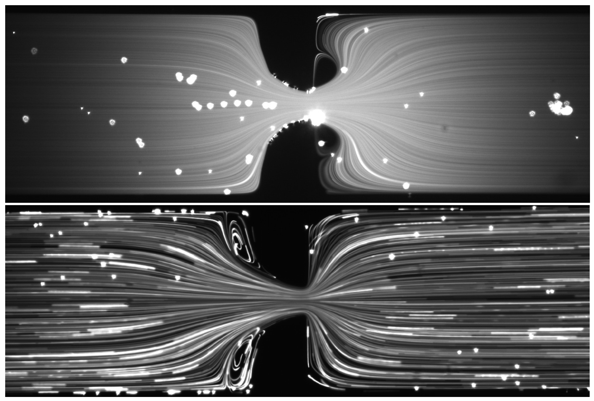
Viscoelasticity makes a big difference in the fluid flow around the prototypes. They behave in a different way depending on the flow conditions. For instance, Coelho and Pinho [64,65,66] studied at the macro scale the influence of the elasticity in the critical Reynolds number for different flow regimes. The presence of elasticity can increase the drag reduction at low Reynolds numbers. In the shear-layer transition regime, the increase of the wake angle and pressure rise coefficient reduced the drag coefficient and narrowed the near wake. At the micro scale, the relevance of fluid elasticity is enhanced and elastic instabilities can be observed easily even at low or negligible Re [7,67]. Campo-Deaño et al. [54] showed that, for a viscoelastic fluid (Boger fluid), symmetric vortices started to form upstream of a hyperbolic contraction at a critical Re of 0.82; meanwhile, for the same micro channel and flow conditions, for a Newtonian fluid, the critical Re at which symmetric vortices start to form downstream of the hyperbolic contraction is higher (Re = 49.3) due to inertial effects (Figure 2).
It has also been reported that, in viscoelastic fluids, both enhancement and inhibition of swimming of some microorganisms’ speed occurs depending on the swimming strategy and the rheological characteristics of the media. For instance, helical bacteria such as Leptospira and B. burgdorferi swims faster in a viscoelastic fluid than in a Newtonian fluid of the same viscosity [68,69], whereas C. elegans, which undulates its body in a planar wave, swims at a slower pace [70]. Zhu et al. [71] studied numerically the locomotion of spherical swimmers with tangential squirming motion in a viscoelastic fluid. They reported that the swimming speed of the viscoelastic fluid decreased in relation to the Newtonian fluid in all the cases analyzed, and also the required power for swimming is smaller for the viscoelastic fluid in addition to the hydrodynamic efficiency being higher than for the Newtonian case. Experiments carried out by Dasgupta et al. [72] to measure the speed of a swimmer immersed in Newtonian and viscoelastic fluids revealed differences between a viscoelastic fluid that has a viscosity independent of shear rate (Boger fluid) and more complex shear-thinning viscoelastic fluids that have multiple relaxation time scales. In the latter case, the speed was slower than in the Boger-like fluid. This is a controversial issue, and there is not yet a consensus with experimental studies leading to clarify whether viscoelasticity increases or decreases swimming velocity. Riley and Lauga [73] considered the general problem of swimming using small-amplitude periodic waves in a viscoelastic fluid described by the classical Oldroyd-B constitutive relationship, and they showed that if all travelling waves move in the same direction, the locomotion speed of the organism is systematically decreased. However, if the waves travel in two opposite directions, this can lead to enhancement of the swimming speed. Nevertheless, more investigation is still needed to check if the theoretical models are in agreement with biological tests.

4.1.3. Steady and Unsteady Blood Flows

The blood flow is generally laminar, with a smooth and ordered fluid motion. The values of the Reynolds number in the human circulatory system can vary until seven orders of magnitude depending on the geometry of the vessel (Table 1), and also, in some cases when the flow emerges from a narrow opening into a larger region in the form of a jet, the blood flow can be considered turbulent, as happens in stenosed arteries. Although the blood flow is considered in most of the cases laminar, it is unsteady, especially at the capillary level.
The pulsatile nature of the blood flow in arteries is due to the cyclic nature of the heart pump. The heart ejects and fills with blood in alternating cycles called systole (blood is pumped out) and diastole (no blood is pumped). Due to the different shape of the vessel of the circulatory system, the pressure and flow have different characteristic pulsatile shapes [75]. The Womersley number is defined as the ratio between the unsteady and viscous forces. For low values, viscous forces dominate, velocity profiles are parabolic in shape, and the centerline velocity oscillates in phase with the driving pressure gradient. On the other hand, for values ≥10, the unsteady inertial forces dominate, and the flow presents a flat velocity profile [76].
Nevertheless, an steady flow could be an acceptable approximation for some experimental and numerical works. In addition, the fluid structure interaction (FSI) is commonly not taken into account for simplification. More information about the steady and unsteady hemodynamic flows can be found in Campo-Deaño et al. [57].

4.2. Experimental Techniques

For the study of the dynamic performance of microbots immersed in viscoelastic biofluids, it is common to use simplified microbot prototypes based on living organisms as real bacteria or spermatozoa. For instance, Martinez-Aranda et al. [77] used different prototype morphology starting from square size to most blender geometries as ellipsoids with different aspect ratios. One example of these prototypes is shown in Figure 3, and the image represents an ellipsoid 1:2 in a straight fused silica microchannel.
Flow visualizations, pressure drop measurements, μ -PIV, and birefringence analysis are the most suitable experimental techniques to be developed in a micro hydrodynamic tunnel for the assessment of the dynamic performance of microbots. For improving the microbot morphology in order to increment its dynamic performance, and to minimize the impact of its presence inside the patient’s body, it is important to relate theoretically the drag force, velocity field and pressure drop with the rheological nature of the fluid and the morphology of the microdevice.

4.2.1. Flow Visualization

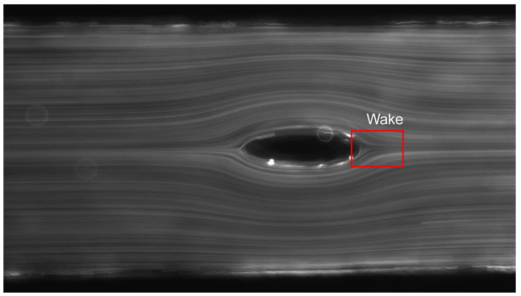
In order to perform flow visualization, the flow streak-line photography technique is a method in which the fluid is seeded with suitable tracer particles, and long-exposure photographs are taken in order to characterize the Lagrangian path of a fluid element particle. With this methodology, an analysis of the path line can be done to assess the length of the wake formed behind the prototype. An example of this type of measurement can be found in Figure 4, where an emerging wake appears. The length of this wake can be calculated using image processing analysis.

4.2.2. μ -PIV

μ -PIV is a flow diagnostic technique that quantifies the velocity field in microfluidic devices [78,79]. This technique measures the local velocity components from the trajectories of tracer particles in an interrogation region over a known time. In these kinds of measurements, the microchannel is placed on the imaging stage of an inverted confocal microscope equipped with objective lenses. The confocal microscope is able to deliver extremely thin images by true means of depth-wise optical slicing, and allows the gathering of 3D reconstructed information from the line of sight depth-wise resolved imaging without the need for physical slicing of specimens. A CCD (Charge-Coupled Device) camera connected to the microscope is used to acquire the images. A double-pulsed 532 nm wavelength Nd:YAG laser system is normally used for volume illumination and 0.5–2 μ m diameter fluorescent particles at a concentration of ∼20–300 ppm for the solids fraction are used as tracer particles. An epifluorescent filter cube will also be used to prevent the laser light from reaching the sensor of the camera, then receiving only the light emitted by the fluorescent particles. The time lapse between two consecutive frames is adjusted depending on the flow rate in order to ensure that the frame by frame particle displacement is optimal for subsequent analysis using an adaptive cross-correlation PIV algorithm with interrogation areas typically ranging from 16 × 16 pixels to 32 × 64 pixels, depending on the lens used. For each experiment, a minimum of 100 image pairs should be recorded and processed to perform an averaged cross-correlation analysis using a specific software in order to obtain the velocity field in the test section.
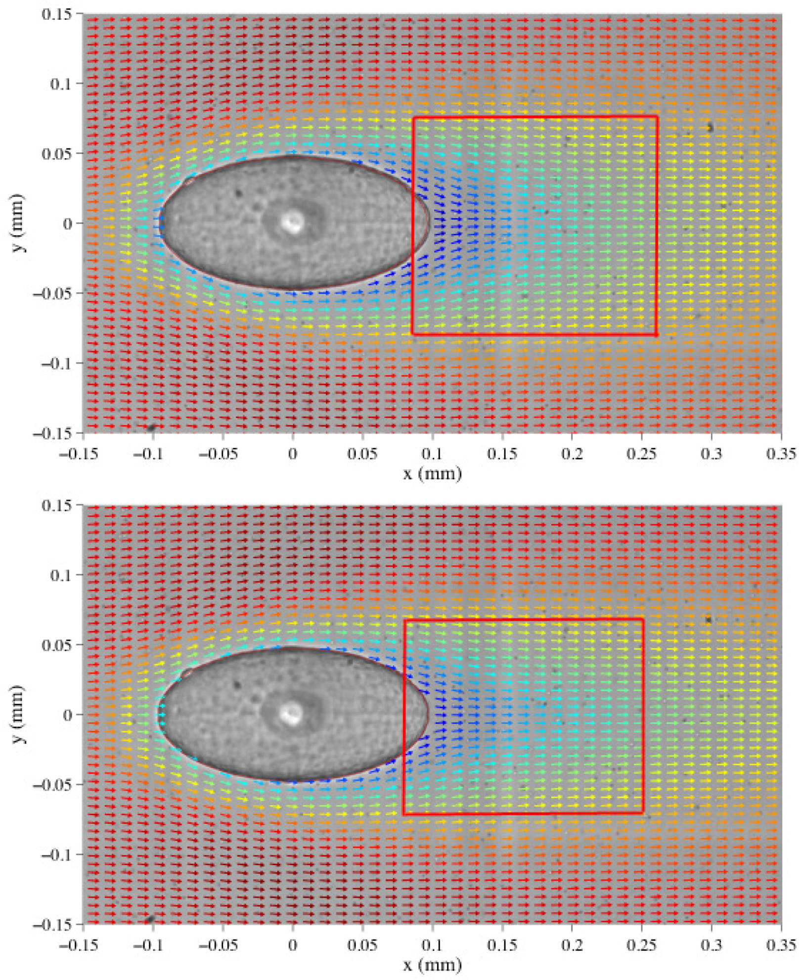
Images in Figure 5 show the velocity vectors of the fluid flow around an ellipsoid of 1:2 for a Newtonian (up) and for a viscoelastic (down) fluid. The differences between these two kind of fluids are clear. In the case of the fluid with elasticity and shear-thinning, the wake is sharper than for the Newtonian case at the same Re, which is in agreement with the region where the highest normal stresses are expected [77].

4.2.3. Pressure Drop Measurements

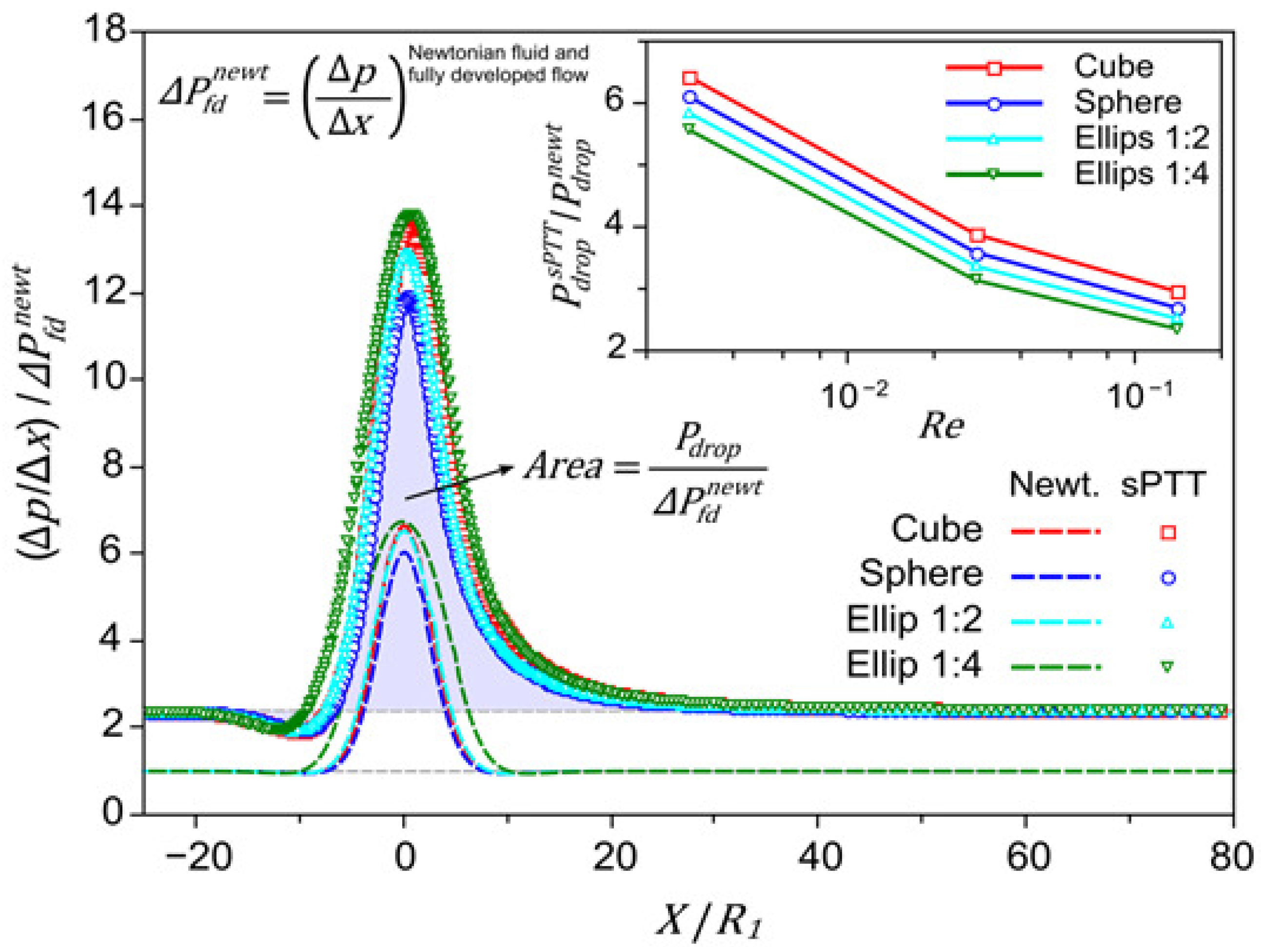
Pressure drop measurements will be also important in order to study the impact of the presence of the microbot in the channel walls during the flow. Figure 6 shows the numerical results of CFD simulations using Newtonian and viscoelastic model (Simplified-Phan-Thien-Tanner model, sPTT) for blood flow. It is clear that the pressure drop is higher for the viscoelastic case in relation to the Newtonian prediction for all the microbot prototypes studied.
Most of the micro pressure sensors normally used in microfluidics are capacitive and piezoresistive sensors, although there are also other types of sensors such as optical and resonant devices or microphones and hydroplanes, but their use is very scarce. These commercial differential pressure sensors should be previously calibrated using a static column of water. A 12V DC power supply is used to power the pressure sensors that were also connected to a computer via a data acquisition card in order to record the output data using LabView software (National Instruments Corporation, Austin, Texas, U.S.). The transient response of the pressure sensors is continuously recorded until a steady-state is reached.

4.2.4. Optical Birefringence

In the case of transparent polymers, birefringence is directly proportional to stress, and thus birefringence measurement provides an excellent method to obtain stress fields [6]. Optical birefringence generates a contour map of stresses; in order to obtain an optical birefringence pattern, the flowing sample is illuminated with monochromatic light. A 4 mW helium-neon laser is positioned such that the beam passes orthogonally through the walls of the flow cell and the observation area. The laser beam is detected by the cooled CCD camera, which is focussed on the stagnation point area. The polarizer and analyser are placed on either side of the flow cell with their axes at 45 to the flow axis, and at 90 to each other to minimize the signal received by the CCD camera. A λ/4 plate is inserted between the polarizer and analyser to compensate for residual birefringence in the walls of the channel. The λ/4 plate is rotated to achieve the minimum signal, and the polarizer and analyser are readjusted iteratively to achieve extinction of the beam. Twenty-five ms images are normally captured for a range of flow rates. When the flow is stopped, a 25 ms background image was captured. The background image was subtracted from the images captured under flow to reveal the birefringent signal. This is done within 1 s to provide the best possible background image for subtraction. The intensity of the detected signal was calibrated by placing a λ/30 compensator in the optical line. The change in the signal intensity is measured as the compensator is rotated to produce a range of retardation values. The retardation, R, is related to the birefringence, Δ n , by R = Δ n l, where l is the path-length through the birefringent material. Then, from Δ n , it is possible to obtain the normal stress and the shear stress actuating on the walls prototypes [82].
The stress-optic law states that the index of refraction tensor is proportional to the stress tensor according to Equations (1) and (2):
σ 12 = 1 2 C Δ n s i n ( 2 α ) ,
σ 11 σ 22 = 1 C Δ n c o s ( 2 α ) ,
where C is the stress-optic coefficient that is independent of molecular weight, polydispersity, and also is independent of polymer concentration over a wide range of compositions [83,84].

4.3. Comparison of Experimental Techniques

The experimental techniques mentioned above have been widely used in the study of the flow dynamics in micro channels; however, they have inherent advantages and disadvantages that are worthy of mentioning and analyzing.
Flow visualization is able to provide a quick and qualitative assessment of a flow field, that is, it allows identification of the flow distribution and flow regimes by the analysis of the streamlines without any post processing and time consumption. It is also an excellent tool to support the quantitative results provided by other techniques like μ -PIV. μ -PIV is used for the assessment of the velocity field. There are also other techniques such as micro Laser Doppler Velocimetry ( μ -LDV) and hot-wire anemometry to measure flows; however, they only provide the velocity at a point and not the two-dimensional or even three-dimensional vector fields as μ -PIV does. Therefore, it has several advantages as the capability of measuring flows in 3D or the high degree of accuracy. On the other hand, disadvantages worth mentioning are that it requires a proper selection of seeding particles and the high cost of its setup. For these two techniques (flow visualization and μ -PIV), the capture of fast transient phenomena on a microscale requires the use of a high speed camera.
Pressure drop measurements provide valuable information between different points along the micro channel. However, very accurate measurements are still a challenge. The problems are mainly related to the design of the micro channels where the pressure taps are located, and the presence of air and the surface tension play an important roles in complicating the measurement process.
Flow birefringence is generally considered as a very convenient method for measuring the stress distribution in polymer melts, and one advantage is that it can be applied without disturbing the flow field. However, it is worthy to address that, in spite of being a valuable experimental technique, it requires the use of birefringent materials, and this fact introduces a restriction to the fluids being used.

4.4. Performance Assessment

From the combination of some of these parameters, it is possible to calculate the drag force due to the viscoelastic flow around the model. The drag force can be described in terms of the wall shear stresses, due to viscous effects and normal stresses due to the pressure. Both wall shear stress and pressure vary in magnitude and direction along the surface. Thus, it is useful to know the detailed distribution of shear stress and pressure over the surface of the body to calculate the drag force, which is given by the following equation (Equation (3)):
F D = A d F x = A p c o s θ d A + A τ w s i n θ d A .
This implies that, apart from knowing the wall shear stress, it is important to know the pressure distribution along the surface of the body. The calculation of this pressure, as it was mentioned previously, is sometimes difficult due to the experimental limitations, and a good approximation would be the calculation of the pressure difference before and after the object. Nevertheless, CFD simulations are, in this case, an excellent tool to determine the pressure surface distribution around the object, and, subsequently, to calculate the drag force combining experimental and numerical techniques.
In order to propose a complete performance parameter, a combination of the result of these experimental techniques is crucial. Therefore, it is expected that a low pressure drop around the microbot, small length of the wake behind the object, low disturbance of the velocity field and low stress field would be the key combination for the maximum efficiency.
To theoretically conceive the morphology of the prototypes to get the optimum design as a function of the maximum performance, optimization numerical techniques, able to combine the characteristics of the object and the fluid flow conditions, are also available to determine the morphology able to diminish the drag and flow disturbance [85,86].
Martinez-Aranda et al. [77] also proposed an efficiency parameter that, in terms of energy dissipated in the flow by the presence of the object, allowed for classification of better efficiency of different microbot prototypes. Nevertheless, the drag force experienced by the prototypes was not reported.

5. Conclusions

The recent interest in the development of microbots for their use in biomedicine has been greatly increasing in the last years. Many published studies investigating the fabrication method of these devices, the remote control, and communication have emerged. However, none of the works in literature have been dealing with the morphology optimization of the microbot prototypes in order to achieve a higher dynamic performance on their movement. In this review paper, we proposed a methodology to assess the efficiency of the movement of the microbots based on different experimental techniques. Flow visualizations, μ -PIV, pressure drop measurements and optical birefringence tests were revealed as a good combination to evaluate the dynamic performance. The length of the wake behind the object, the velocity field, the change of pressure due to the presence of the object and the stress field are obtained from these techniques, respectively.
It is important to point out that this methodology constitutes a good tool for assessing the dynamic performance of microbots; however, a more realistic methodology would significantly improve this process. In this sense, fluid structure interactions that play an important role in the flow behavior is an interesting contribution. Therefore, it would be important to develop more complex geometries as patient-specific models in order to be closer to the real physiological and anatomic characteristics of the human body.

Acknowledgments

The author would like to acknowledge Francisco J. Galindo-Rosales for fruitful discussions and the financial support provided by Fundação para a Ciência e a Tecnologia (FCT), COMPETE and FEDER through Grant IF/00148/2013.

Conflicts of Interest

The author declares no conflict of interest.

Abbreviations

The following abbreviations are used in this manuscript:
ReReynolds number
WiWeissemberg number
G’storage modulus
G”loss modulus
μ -PIVmicro-Particle Image Velocimetry
CFDComputational Fluid Dynamics
FSIFluid Structure Interaction
σ 12 shear stress
σ 11 σ 22 first normal stress difference

References

  1. Thurston, G.B. Rheological parameters for the viscosity, viscoelasticity and thixotropy of blood. Biorheology 1979, 16, 149–162. [Google Scholar] [PubMed]
  2. Dintenfass, L. Blood Rheology in Cardio-vascular Diseases. Nature 1963, 199, 813–815. [Google Scholar] [CrossRef] [PubMed]
  3. Langstroth, L. Blood Viscosity. I Conditions affecting the viscosity of blood after withdrawal from the body. J. Exp. Med. 1919, 30, 597–606. [Google Scholar] [CrossRef] [PubMed]
  4. Chien, S.; Usami, S.; Dellenback, R.J.; Gregersen, M.I. Blood viscosity: Influence of erythrocyte deformation. Science 1967, 157, 827–829. [Google Scholar] [CrossRef] [PubMed]
  5. Chien, S.; Usami, S.; Dellenback, R.J.; Gregersen, M.I.; Nanninga, L.B.; Guest, M.M. Blood viscosity: Influence of erythrocyte aggregation. Science 1967, 157, 829–831. [Google Scholar] [CrossRef] [PubMed]
  6. Morrison, F.A. Understanding Rheology; Oxford University Press, Inc.: Oxford, UK, 2001. [Google Scholar]
  7. Galindo-Rosales, F.J.; Campo-Deaño, L.; Sousa, P.C.; Ribeiro, V.M.; Oliveira, M.S.N.; Alves, M.M.; Pinho, F.T. Viscoelastic instabilities in micro-scale flows. Exp. Ther. Fluid Sci. 2014, 59, 128–139. [Google Scholar] [CrossRef] [Green Version]
  8. Haberzettl, C.A. Nanomedicine: Destination or journey? Nanotechnology 2002, 13, R9–R13. [Google Scholar] [CrossRef]
  9. Nelson, B.J.; Kaliakatsos, I.K.; Abbott, J.J. Microrobots for minimally invasive medicine. Annu. Rev. Biomed. Eng. 2010, 12, 55–85. [Google Scholar] [CrossRef] [PubMed]
  10. Takeda, M. Applications of MEMS to Industrial Inspection. In Proceedings of the 14th IEEE International Conference on Micro Electro Mechanical Systems, Interlaken, Switzerland, 21–25 January 2001.
  11. Ghanbari, A.; Bahrami, M. A Novel Swimming Microrobot Based on Artificial Cilia for Biomedical Applications. J. Intell. Robot. Syst. 2011, 63, 399–416. [Google Scholar] [CrossRef]
  12. Martel, S. Magnetic Microbots to Fight Cancer; IEEE Spectrum: New York, NY, USA, 2012. [Google Scholar]
  13. Kummer, M.P.; Abbott, J.J.; Dinser, S.; Nelson, B.J. Artificial Vitreous Humor for in vitro experiments. In Proceedings of the 29th Annual International Conference of the IEEE EMBS Cite Internationale, Lyon, France, 23–26 August 2007.
  14. Ergeneman, O.; Chatzipirpiridis, G.; Pokki, J.; Marin-Suarez, M.; Sotiriou, G.A.; Medina-Rodriguez, S.; Sanchez, J.F.; Fernandez-Gutierrez, A.; Pane, S.; Nelson, B.J. In vitro oxygen sensing using intraocular microrobots. IEEE Trans. Biomed. Eng. 2012, 59, 3014–3109. [Google Scholar] [CrossRef] [PubMed]
  15. Peyer, K.E.; Siringil, E.C.; Zhang, L.; Suter, M.; Nelson, B.J. Bacteria-inspired magnetic polymer composite microrobots. Lect. Notes Comput. Sci. 2013, 8064, 216–227. [Google Scholar]
  16. Zeeshan, M.; Grisch, R.; Pellicer, E.; Sivaraman, K.M.; Peyer, K.E.; Sort, J.; Ozkale, B.; Sakar, M.S.; Nelson, B.J.; Pane, S. Hybrid helical magnetic microrobots obtained by 3D template-assisted electrodeposition. Small 2014, 10, 1284–1288. [Google Scholar] [CrossRef] [PubMed]
  17. Singh, A.K.; Dey, K.K.; Chattopadhyay, A.; Mandal, T.K.; Bandyopadhyay, D. Multimodal chemo-magnetic control of self-propelling microbots. Nanoscale 2014, 6, 1398. [Google Scholar] [CrossRef] [PubMed]
  18. Solovev, A.A.; Sanchez, S.; Pumera, M.; Mei, Y.F.; Schmidt, O.G. Magnetic control of tubular catalytic microbots for the transport, assembly, and delivery of micro-objects. Adv. Funct. Mater. 2010, 20, 2430–2435. [Google Scholar] [CrossRef]
  19. Fountain, T.W.R.; Kailat, P.V.; Abbott, J.J. Wireless control of magnetic helical microrobots using a rotating-permanent-magnet manipulator. In Proceedings of the IEEE International Conference on Robotics and Automation, Anchorage, AK, USA, 3–7 May 2010.
  20. Abbott, J.J.; Peyer, K.E.; Dong, L.X.; Nelson, B.J. How should microrobots swim? Springer Tracts Adv. Robot. 2011, 66, 157–167. [Google Scholar]
  21. Belharet, K.; Folio, D.; Ferreira, A. Three-dimensional controlled motion of a microrobot using magnetic gradients. Adv. Robot. 2011, 25, 1069–1083. [Google Scholar] [CrossRef]
  22. Palagi, S.; Jager, E.W.H.; Mazzolai, B.; Beccai, L. Propulsion of swimming microrobots inspired by metachronal waves in ciliates: from biology to material specifications. Bioinspir. Biomim. 2013, 8, 046004. [Google Scholar] [CrossRef] [PubMed]
  23. Sharafi, A.; Olamaei, N.; Martel, S. A new communication method for untethered intelligent microrobots. In Proceedings of the IEEE/ASME International Conference on Advanced Intelligent Mechatronics (AIM), Wollongong, Australia, 9–12 July 2013.
  24. Corradi, P.; Scholz, O.; Knoll, T.; Menciassi, A.; Dario, P. An optical system for communication and sensing in millimeter-sized swarming microrobots. J. Micromech. Microeng. 2009, 19, 015022. [Google Scholar] [CrossRef]
  25. Boillot, N.; Dhoutaut, D.; Bourgeois, J. Using nano-wireless communications in micro-robots applications. In Proceedings of the NANOCOM 2014, 1st ACM International Conference on Nanoscale Computing and Communication, Atlanta, GA, USA, 6–9 May 2014.
  26. Taylor, G.I. Analysis of the swimming of microscopic organisms. Proc. R. Soc. Lond. A 1951, 209, 447–461. [Google Scholar] [CrossRef]
  27. Berg, H.C.; Anderson, A.R. Bacteria swim by rotating their flagellar filaments. Nature 1973, 245, 380–382. [Google Scholar] [CrossRef] [PubMed]
  28. Peyer, K.E.; Zhang, L.; Nelson, B.J. Bio-inspired magnetic swimming microrobots for biomedical applications. Nanoscale 2013, 5, 1259–1272. [Google Scholar] [CrossRef] [PubMed]
  29. Mellal, L.; Belharet, K.; Folio, D.; Ferreira, A. Optimal structure of particles-based super paramagnetic micro robots: Application to MRI guided targeted drug therapy. J. Nanopart. Res. 2015, 17, 2–18. [Google Scholar] [CrossRef]
  30. Qiu, T.; Lee, T.C.; Mark, A.G.; Morozov, K.I.; Munster, R.; Mierka, O.; Turek, S.; Leshansky, A.M.; Fischer, P. Swimming by reciprocal motion at low Reynolds number. Nat. Commun. 2014, 4, 5119. [Google Scholar] [CrossRef] [PubMed]
  31. Walker, D.; Kubler, M.; Morozov, K.I.; Fischer, P.; Leshansky, A.M. Optimal length of low Reynolds Number nano propellers. Nano Lett. 2015, 15, 4412–4416. [Google Scholar] [CrossRef] [PubMed]
  32. Venugopalan, P.L.; Sai, R.; Chandorkar, Y.; Basu, B.; Shivashankar, S.; Ghosh, A. Conformal Cytocompatible Ferrite Coatings Facilitate the Realization of a Nanovoyager in Human Blood. Nano Lett. 2014, 14, 1968–1975. [Google Scholar] [CrossRef] [PubMed]
  33. Schamel, D.; Mark, A.G.; Gibbs, J.G.; Miksch, C.; Morozov, K.I.; Leshansky, A.M.; Fischer, P. Nanopropellers and their actuation in complex viscoelastic media. ACS Nano 2014, 8, 8794–8801. [Google Scholar] [CrossRef] [PubMed]
  34. Temel, F.Z.; Yesilyurt, S. Simulation-based analysis of micro-robots swimming at the center and near the wall of circular mini-channels. Microfluid. Nanofluid. 2013, 14, 287–298. [Google Scholar] [CrossRef] [Green Version]
  35. Temel, F.Z.; Yesilyurt, S. Confined swimming of bio-inspired microrobots in rectangular channels. Bioinspir. Biomim. 2015, 10, 016015. [Google Scholar] [CrossRef] [PubMed]
  36. Tang, Y.; Chen, C.; Khaligh, A. An ultra compact dual-stage converter for driving electrostatic actuators in mobile microrobots. IEEE Trans. Power Electron. 2014, 29, 2991–3000. [Google Scholar] [CrossRef]
  37. Donald, B.R.; Levey, C.G.; McGray, C.D.; Paprotny, I.; Rus, D. An untethered, electrostatic, globally controllable MEMS micro-robot. J. Microelectromech. Syst. 2006, 15, 1–15. [Google Scholar] [CrossRef]
  38. Graule, M.A.; Chirarattananon, P.; Fuller, S.B.; Jafferis, N.T.; Ma, K.Y.; Spenko, M.; Kornbluh, R.; Wood, R.J. Perching and Takeoff of a robotic insect on overhangs using switchable electrostatic adhesion. Science 2016, 352, 978–982. [Google Scholar] [CrossRef] [PubMed]
  39. Pawashe, C.; Floyd, S.; Sitti, M. Multiple magnetic micro robot control using electrostatic anchoring. Appl. Phys. Lett. 2009, 94, 164108. [Google Scholar] [CrossRef]
  40. Mahoney, A.W.; Abbott, J.J. Five-degree-of-freedom manipulation of an untethered magnetic device in fluid using a single permanent magnet with application in stomach cap sue endoscopy. Int. J. Robot. Res. 2016, 35, 129–147. [Google Scholar] [CrossRef]
  41. Diller, E.; Giltinan, J.; Sitti, M. Independent control of multiple magnetic micro robots in three dimensions. Int. J. Robot. Res. 2013, 32, 614–631. [Google Scholar] [CrossRef]
  42. Diller, E.; Giltinan, J.; Lum, G.Z.; Ye, Z.; Sitti, M. Six-degree-of-freedom magnetic actuation for wireless micro robotics. Int. J. Robot. Res. 2016, 35, 114–128. [Google Scholar] [CrossRef]
  43. Floyd, S.; Diller, E.; Pawashe, C.; Sitti, M. IControl methodologies for a heterogeneous group of untethered magnetic micro-robots. Int. J. Robot. Res. 2011, 30, 1553–1565. [Google Scholar] [CrossRef]
  44. Chowdhury, S.; Jing, W.; Cappelleri, D.J. Controlling multiple micro robots: Recent progress and future challenges. J. Micro-Bio Robot. 2015, 10, 1–11. [Google Scholar] [CrossRef]
  45. Hu, W.; Ishii, K.S.; Ohta, A.T. Micro-assembly using optically controlled bubble microrobots. Appl. Phys. Lett. 2011, 99, 094103. [Google Scholar] [CrossRef]
  46. Lozano, C.; Hagen, B.T.; Löwen, H.; Bechinher, C. Phototaxis of synthetic micro swimmers in optical landscapes. Nat. Commun. 2016, 7, 12828. [Google Scholar] [CrossRef]
  47. Palagi, S.; Mark, A.G.; Reigh, S.Y.; Melde, K.; Qiu, T.; Zeng, H.; Parmeggiani, C.; Martella, D.; Sanchez-Castillo, A.; Kapernaum, N.; et al. Structured light enables biomimetic swimming and versatile locomotion of photo responsive soft microrobots. Nat. Mater. 2016, 15, 647–653. [Google Scholar] [CrossRef] [PubMed]
  48. Sanchez, S.; Solovev, A.A.; Schulze, S.; Schmidt, O.G. Controlled manipulation of multiple cells using catalytic microbots. Chem. Commun. 2011, 47, 698–700. [Google Scholar] [CrossRef] [PubMed]
  49. Srivastava, S.K.; Guix, M.; Schmidt, O.G. Wastewater mediated activation of micro motors for efficient water cleaning. Nano Lett. 2016, 16, 817–821. [Google Scholar] [CrossRef] [PubMed]
  50. Dey, K.K.; Bhandari, S.; Bandyopadhyay, D.; Basu, S.; Chattopadhyay, A. The pH taxis of an intelligent catalytic microbot. Small 2013, 9, 1916–1920. [Google Scholar] [CrossRef] [PubMed]
  51. Carlsen, R.W.; Edwards, M.R.; Zhuang, J.; Pacoret, C.; Sitti, M. Magnetic steering control of multi-cellular bio-hybrid microswimmers. Lab Chip 2014, 14, 3850. [Google Scholar] [CrossRef] [PubMed]
  52. Williams, B.J.; Anand, S.V.; Rajagopalan, J.; Saif, M.T.A. A self-propelled biohybrid swimmer at low Reynolds number. Nat. Commun. 2014, 5, 3081. [Google Scholar] [CrossRef] [PubMed]
  53. Medina-Sánchez, M.; Schwarz, L.; Meyer, A.K.; Hebenstreit, F.; Schmidt, O.G. Cellular cargo delivery: Toward assisted fertilization by sperm-carrying micromotors. Nano Lett. 2016, 16, 555–561. [Google Scholar] [CrossRef] [PubMed]
  54. Campo-Deaño, L.; Galindo-Rosales, F.J.; Pinho, F.T.; Alves, M.M.; Oliveira, M.S.N. Flow of low viscosity Boger fluids through a microfluidic hyperbolic contraction. J. Non-Newton. Fluid Mech. 2011, 166, 1286–1296. [Google Scholar] [CrossRef] [Green Version]
  55. Galindo-Rosales, F.J.; Campo-Deaño, L.; Pinho, F.T.; van Bokhorst, E.; Hamersma, P.J.; Oliveira, M.S.N.; Alves, M.M. Microfluidic system for the analysis of viscoelastic effects in flow through porous media. Microfluid. Nanofluid. 2012, 12, 485–498. [Google Scholar] [CrossRef] [Green Version]
  56. Sousa, P.C.; Pinho, F.T.; Alves, M.A.; Oliveira, M.S.N. A review of hemorheology: measuring techniques and recent advances. Korea-Aust. Rheol. J. 2016, 28, 1–22. [Google Scholar] [CrossRef] [Green Version]
  57. Campo-Deaño, L.; Oliveira, M.S.N.; Pinho, F.T. A review of computational hemodynamics in middle cerebral aneurysms and rheological models for blood flow. Appl. Mech. Rev. 2015, 67, 030801. [Google Scholar] [CrossRef]
  58. Chen, D.T.N. Microrheology of Soft Matter. Ph.D. Thesis, University of Pennsylvania, Philadelphia, PA, USA, 2010. [Google Scholar]
  59. Schultz, K.M.; Furst, E.M. Microrheology of biomaterial hydrogelators. Soft Matter 2012, 8, 6198–6205. [Google Scholar] [CrossRef]
  60. Campo-Deaño, L.; Dullens, R.P.A.; Aarts, D.G.L.A.; Pinho, F.T.; Oliveira, M.S.N. Viscoelasticity of blood and viscoelastic blood analogues for use in polydymethylsiloxane in vitro models of the circulatory system. Biomicrofluidics 2013, 7, 034102. [Google Scholar] [CrossRef] [PubMed]
  61. Jeong, H.H.; Mark, A.G.; Lee, T.C.; Alarcón-Correa, M.; Eslami, S.; Qiu, T.; Gibbs, J.G.; Fischer, P. Active Nanorheology with Plasmonics. Nano Lett. 2016, 16, 4887–4894. [Google Scholar] [CrossRef] [PubMed]
  62. Landau, L.D.; Akhiezer, A.I.; Lifshitz, E.M. General Physics: Mechanics and Molecular Physics; Pergamon Press: Oxford, UK, 1967. [Google Scholar]
  63. Martínez-Aranda, S.; Galindo-Rosales, F.J.; Campo-Deaño, L. Complex Fluid Dynamics of Swimming Microbots; Flowing Matter 2014: Lisboa, Portugal, 2014. [Google Scholar]
  64. Coelho, P.M.; Pinho, F.T. Vortex shedding in cylinder flow of shear-thinning fluids III. Pressure measurements. J. Non-Newton. Fluid Mech. 2004, 121, 55–68. [Google Scholar]
  65. Coelho, P.M.; Pinho, F.T. Vortex shedding in cylinder flow of shear-thinning fluids II. Flow characteristics. J. Non-Newton. Fluid Mech. 2003, 110, 177–193. [Google Scholar] [CrossRef]
  66. Coelho, P.M.; Pinho, F.T. Vortex shedding in cylinder flow of shear-thinning fluids I. Identification and demarcation of flow regimes. J. Non-Newton. Fluid Mech. 2003, 110, 143–176. [Google Scholar] [CrossRef]
  67. Sousa, P.C.; Pinho, F.T.; Oliveira, M.S.N.; Alves, M.M. Purely elastic flow instabilities in micro scale cross-slot devices. Soft Matter 2015, 11, 8856. [Google Scholar] [CrossRef] [PubMed] [Green Version]
  68. Berg, H.C.; Turner, L. Movement of microorganisms in viscous environments. Nature 1979, 278, 349–351. [Google Scholar] [CrossRef] [PubMed]
  69. Kimsey, R.B.; Spielman, A. Motility of Lyme Disease Spirochetes in Fluids as Viscous as the Extracellular Matrix. J. Infect. Dis. 1990, 162, 1205–1208. [Google Scholar] [CrossRef] [PubMed]
  70. Shen, X.N.; Arratia, P.E. Undulatory Swimming in Viscoelastic Fluids. Phys. Rev. Lett. 2011, 106, 208101. [Google Scholar] [CrossRef] [PubMed]
  71. Zhu, L.; Lauga, E.; Brandt, L. Self-propulsion in viscoelastic fluids: Pushers vr. pullers. Phys. Fluids 2012, 24, 051902. [Google Scholar] [CrossRef]
  72. Dasgupta, M.; Liu, B.; Fu, H.C.; Berhanu, M.; Breuer, K.S.; Powers, T.R.; Kudrolli, A. Speed of a swimming sheet in Newtonian and viscoelastic fluids. Phys. Rev. E 2013, 87, 013015. [Google Scholar] [CrossRef] [PubMed]
  73. Riley, E.E.; Lauga, E. Small-amplitude swimmers can self-propel faster in viscoelastic fluids. J. Theor. Biol. 2015, 382, 345–355. [Google Scholar] [CrossRef] [PubMed]
  74. Berger, S.A.; Goldsmith, W.; Lewis, E.R. Introduction to Bioengineering; Oxford University Press: Oxford, UK, 1996. [Google Scholar]
  75. Ku, D.N. Blood Flow in Arteries. Annu. Rev. Fluid Mech. 1997, 29, 399–434. [Google Scholar] [CrossRef]
  76. Womersley, J.R. Method for the calculation of velocity, rate of flow and viscous drag in arteries when the pressure gradient is known. J. Physiol. 1955, 127, 553–563. [Google Scholar] [CrossRef] [PubMed]
  77. Martínez-Aranda, S.; Galindo-Rosales, F.J.; Campo-Deaño, L. Complex flow dynamics around 3D microbot prototypes. Soft Matter 2016, 12, 2334. [Google Scholar] [CrossRef] [PubMed]
  78. Santiago, J.G.; Werely, S.T.; Meinhart, C.D.; Beebe, D.J.; Adrian, R.J. A particle image velocimetry system for microfluidics. Exp. Fluids 1998, 25, 316–319. [Google Scholar] [CrossRef]
  79. Meinhart, C.D.; Werely, S.T.; Gray, M.H.B. Volume illumination for two-dimensional particle image velocimetry. Meas. Sci. Technol. 2000, 11, 809. [Google Scholar] [CrossRef]
  80. Martínez-Aranda, S.; Galindo-Rosales, F.J.; Campo-Deaño, L. Blood flow dynamics around bioinspired microbots. In Proceedings of the 6th Iberian Meeting on Colloids and Interfaces (RICI6), Guimarẽs, Portugal, 8–10 July 2015.
  81. Martínez-Aranda, S.; Galindo-Rosales, F.J.; Campo-Deaño, L. Numerical Study on the Influence of the Swimming Microbot’s Morphology in Human Blood Flow. In Proceedings of the Annual Meeting on Rheology of the Society of Rheology, Philadelphia, PA, USA, 5–9 October 2014.
  82. Mitsoulis, E. Numerical simulation of confined flow of polyethylene melts around a cylinder in a planar channel. J. Non-Newton. Fluid Mech. 1998, 76, 327–350. [Google Scholar] [CrossRef]
  83. Takahashi, T.; Fuller, G. Stress tensor measurement using birefringence in oblique transmission. Rheol. Acta 1996, 35, 297–302. [Google Scholar] [CrossRef]
  84. Larson, R.G.; Khan, S.A.; Raju, V.R. Relaxation of Stress and Birefringence in Polymers of High Molecular Weight. J. Rheol. 1988, 32, 145–161. [Google Scholar] [CrossRef]
  85. Jensen, K.E.; Szabo, P.; Okkels, F. Topology optimization of viscoelastic rectifiers. Appl. Phys. Lett. 2012, 100, 234102. [Google Scholar] [CrossRef] [Green Version]
  86. Galindo-Rosales, F.J.; Oliveira, M.S.N.; Alves, M.M. Optimized cross-slot microdevices for homogeneous extension. RSC Adv. 2014, 4, 7799–7804. [Google Scholar] [CrossRef] [Green Version]
Figure 1. Computational fluid dynamics simulations for a Newtonian fluid around objects with different morphology at Re = 22.3. The flow direction is from right to left. Adapted from [63].
Applsci 06 00410 g001
Figure 2. Flow patterns for distilled water (Re = 49.3) and 400 ppm polyacrylamide (PAA) solution with 1% NaCl (Re = 0.82). The flow direction is from left to right. Images adapted from Campo-Deaño et al. [54]. Copyright Journal of Non-Newtonian Fluid Mechanics, 2011.
Applsci 06 00410 g002
Figure 3. Scanning Electron Microscopy images of a simplified 3D microbot prototype in a microchannel.
Applsci 06 00410 g003
Figure 4. Example of the formation of a wake in a Newtonian fluid around an ellipsoid. The flow direction is from left to right.
Applsci 06 00410 g004
Figure 5. Velocity vector for a fluid flow at the same Re. Newtonian fluid (up) and viscoelastic fluid (down). Adapted from [80].
Applsci 06 00410 g005
Figure 6. Normalized static pressure drop distribution along the x-direction for different prototypes (cube, sphere, ellipsoid 1:2 and ellipsoid 1:4) for Newtonian and viscoelastic fluid. Inset: increment of the pressure drop for a viscoelastic fluid with respect to the Newtonian case as a function of Re. Adapted from [81].
Applsci 06 00410 g006
Table 1. Characteristics of different veins and arteries of the human circulatory system and the Reynolds numbers under the peak flow conditions [9,74].
VesselInner Diameter (mm)Blood Velocity (mm/s)Reynolds Number
Aorta254003000
Vena cava3050–3003000
Medium artery4100–400500
Vein53–50150
small arteriole0.031–1000.7
Venule0.02<30.01
Capillary0.008<10.002