Grasping Claws of Bionic Climbing Robot for Rough Wall Surface: Modeling and Analysis


1
School of Mechanical Engineering, Suzhou University of Science and Technology, Suzhou 215009, China
2
College of Automation, Nanjing University of Posts and Telecommunications, Nanjing 210003, China
*
Author to whom correspondence should be addressed.
Appl. Sci. 2018, 8(1), 14; https://doi.org/10.3390/app8010014
Submission received: 16 November 2017
/
Revised: 12 December 2017
/
Accepted: 21 December 2017
/
Published: 22 December 2017
(This article belongs to the Special Issue Bio-Inspired Robotics)
Abstract
:Aiming at the inspection of rough stone and concrete wall surfaces, a grasping module of cross-arranged claw is designed. It can attach onto rough wall surfaces by hooking or grasping walls. First, based on the interaction mechanism of hooks and rough wall surfaces, the hook structures in claw tips are developed. Then, the size of the hook tip is calculated and the failure mode is analyzed. The effectiveness and reliability of the mechanism are verified through simulation and finite element analysis. Afterwards, the prototype of the grasping module of claw is established to carry out grasping experiment on vibrating walls. Finally, the experimental results demonstrate that the proposed cross-arranged claw is able to stably grasp static wall surfaces and perform well in grasping vibrating walls, with certain anti-rollover capability. This research lays a foundation for future researches on wall climbing robots with vibrating rough wall surfaces.
1. Introduction
Climbing robot is a kind of special robot, which can climb and walk on a rough vertical wall or spherical surface. Installed with related equipment, it can clean the wall, detect flaws, lay pipes, and paint, etc.
Wall climbing robots, which are a special operation mechanism in extreme environment generally adhere to walls by virtue of negative suckers, permanent magnets, or bio-inspired adhesion [1,2,3,4,5,6]. However, magnetic adhesion fails for wall surfaces under long-term vibrations, such as diagonal cable bridge towers and viaduct bridge piers. Vacuum adhesion becomes instable due to the influence of vibrating wall surfaces. Bio-inspired viscous materials tend to detach from dusty and rough walls.
The climbing robot with grippers is a kind of climbing mechanism utilizing gripper for grasping and also an important part of climbing robot in the field of mobile robot. These climbing mechanisms are used widely in the domain of robotics. Bartsch et al. [7] designed a hexapod climbing robot based on the bionics principle. The robot could walk freely in an extreme complex environment with some slopes. The climbing robot can also imitate the climbing actions of human being and animals in some specific surfaces. Lam et al. [8] developed a kind of tree-climbing robot with a new flexible movement structure and analyzed the wormlike peristaltic movement to design grippers. They presented an algorithm to increase the motion stability. The robot could stably grasp some irregular objects. Asbeck et al. [9] designed a kind of climbing robot for hard vertical surfaces, which is inspired by the mechanisms that were observed in some climbing insects and spiders. The basic idea is to involve arrays of microspines that could catch on surface asperities.
Sintov et al. [10] proposed a wall-climbing robot with grippers. The robot was similar in structure to the bio-mimetic climbing robot in Reference [9]. There were extremely small barb-like spines on its feet to hook the uplifts on the rough surface. Parness et al. [11] developed a rock-climbing robot with grasping grippers using hook array. Each gripper contained hundreds of flexible hooks. There were distinct differences between bio-mimetic climbing robot and conventional climbing robots in the adsorption principle, movement mode, and appearance, where the former had a strong adaptive capacity on the wall. Liu et al. [12] proposed a climbing robot by imitating tarsi on the leg of Maladera orientalis. Furthermore, the robots were able to climb along the rough wall using the ratchet wheels with hooks arranged into circumference array as driving wheels. Guan et al. [13] desinged a biped modular robot with climbing capacity to replace workers in high risk environments. Wang et al. [14] presented a novel solution for the problem of multi-gaits for snake-like robots. Jiang et al. [15] designed a double claw modular biomimetic robot with climbing and operating functions for aerial work in agriculture, forestry, architecture, and other fields. Kalind et al. [16] proposed a microspine wheel consisting of multiple independent compliant hooks, which can climb up stairs, steps, and rough vertical walls. Arena et al. [17] presented a control system scheme for a biologically inspired walking hexapod robot. The control system is structured as an analog control system realized by Cellular Non-linear Networks (CNNs) generating the locomotion pattern as a function of the sensorial stimuli from the environment.
The power supply is one of the fundamental problems in climbing robots. Buscarino et al. [18] presented a realization and control scheme of a walking microrobot actuated by piezoelectric actuators. The control signals are generated by performing a frequency modulation driven by the chaotic evolution of Chua’s circuit state variables. The role of passive and active vibrations for the control of nonlinear large-scale electromechanical systems is analyzed in Reference [19], which makes it possible to regularize imperfect uncertain large-scale systems.
Applying the mode of gripping walls with tiny hooks, Xu et al. [20] designed a multi-legged wall climbing robot with claws and the mechanical model for the climbing of the robot. The climbing experiment showed that the robot could climb upward on walls. However, when there are large external disturbances (wind loads and wall vibrations), the hooks are likely to detach and thereby result in instable attachment onto the wall. This is because multiple hooks are not flexibly connected and the stress is distributed unevenly. In our work, the bionic claws model of “grabbing the wall” is designed to replace the existing form of hooking claws. The presented grasping claws cause the hook to form a force closure between the hooks and uplifts on the wall, and the active force can be exerted on each hook, so as to overcome the disadvantage of unequal force distribution in the hooking claws. Therefore, the grasping claws can improve the adsorption stability of the claws mechanism.
In this paper, by analyzing the interaction between hooks and rough wall surfaces, a grasping module of cross-arranged claws is designed, the grasping ability and disturbance resistance of wall climbing robots to rough walls are improved. The rest of the paper is organized as follows. The grasping module of cross-arranged claws is designed in Section 2. The minute claw is designed and analyzed in Section 3. The grasping claws module based on ANSYS Workbench is analyzed in Section 4. The experiments for climbing model of bionic robot are carried out in Section 5. Conclusions and future work are discussed in Section 6.
2. Design of the Grasping Module of Cross-Arranged Claws
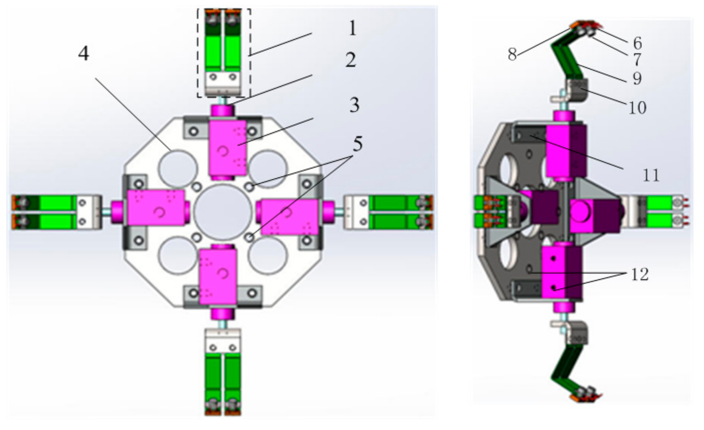
Based on the designed spine structure in Reference [20], two groups of spines were employed to collaboratively realize the grasping, and the grasping module of cross-arranged claws was proposed (Figure 1). Two pairs of secondary claws were installed on the main body, each of which was composed of two pairs of tiny hooks, screw nuts, elastic steel sheets, spring washers, and connecting plates. The two pairs of tiny hooks were symmetrically distributed on the tips of the secondary claws, and were fixed with the screw nuts and the elastic steel sheets. The elastic steel sheets were connected with the secondary claws and a connecting rod.
The grasping module works in accordance with the following principle: the two pairs of secondary claws are symmetrically fixed around the claw module and are connected with the cylinders with connecting rods. Two air injecting holes are drilled on each cylinder and connected with the external air source via hoses. When the air source inflates the cylinder through the inside gas hole, the pressure in the cylinder increases, pushes the connecting rod, and thereby drives the motion of the claws. In this way, it controls the outward stretching of the four claws. When the air source inflates via the outside gas hole, it increases the pressure outside the cylinder, thus pushing the connecting rod to draw back the claws. By doing so, it controls the claws to draw back. Through the stretching or draw back of the connecting rod, the hooks at the tips of claws can slip on rough wall surfaces to search stable points that can be grasped. When large enough friction force is produced between the hook and the rough wall, the elastic steel sheet undergoes elastic deformation on the contact wall surface, which enables the robot to adapt to uneven rough wall surfaces.
The designed cross-arranged claws allow for the robot to more stably attach to wall surfaces, prevent sideslip overturn, and have certain vibration resistance. It dramatically improves the adaptability of robots to walls.
3. Design and Analysis of the Miniature Claws
The interaction mechanism of the micro-hook with the microbulges on wall surfaces suggests that the grabbing effect of the bionic hook on the bulges is directly correlated with the wall surface roughness and the top size of the bionic hook.
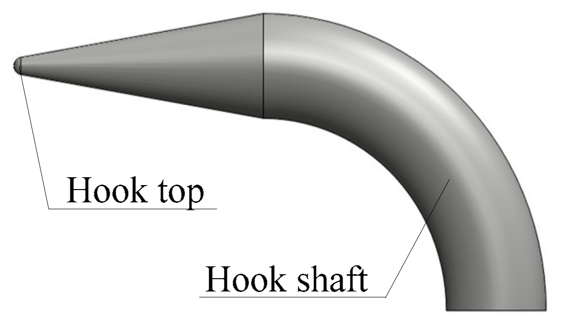
3.1. Calculation of Hook Top Size
The maximum top size of the micro-hook is associated with the linear profile roughness of wall surface , the frictional coefficient between hook and wall , and the average width of wall profile unit . The maximum top size of the micro-hook is derived from Reference [21]. The top size of the micro-hook should be lower than the maximum size. Asbeck et al. [9] established the models of hook and surface profile, and experimentally measured the relationships of the number of unit centimeter micro-bulges with the hook top size, hook load angle, and surface roughness. SpinybotII, the wall-climbing robot, as proposed by Asbeck, had a hook top diameter of and a hook neck diameter of . Dai et al. [22] established the relationship between the hook top sizes with the surface roughness of objects and pointed out that, the stable stressing point could be achieved as long as the hook top radius was lower than the average radius of the micro-bulges on the wall surface. The smaller that the hook top size is, the stronger is the adhering ability on the rough wall surface.
In present study, the concrete surface was taken as an example. Related parameters were measured as follows: surface profile linear roughness , frictional factor between hook and concrete surface , average width of wall profile unit , distance from the centroid of the robot to the wall , and distance of the upper and lower claws of the robot . We derived and the contact angle . Using MATLAB simulation, we calculated that the maximum radius of the micro-hook top (Figure 2) was . We set the radius of the micro-hook top as , which was approximately equivalent to the size calculated by Kim. The accuracy of the interaction model of the micro-hook and the micro-bulges on the wall was also validated.
3.2. Failure Form of Hook
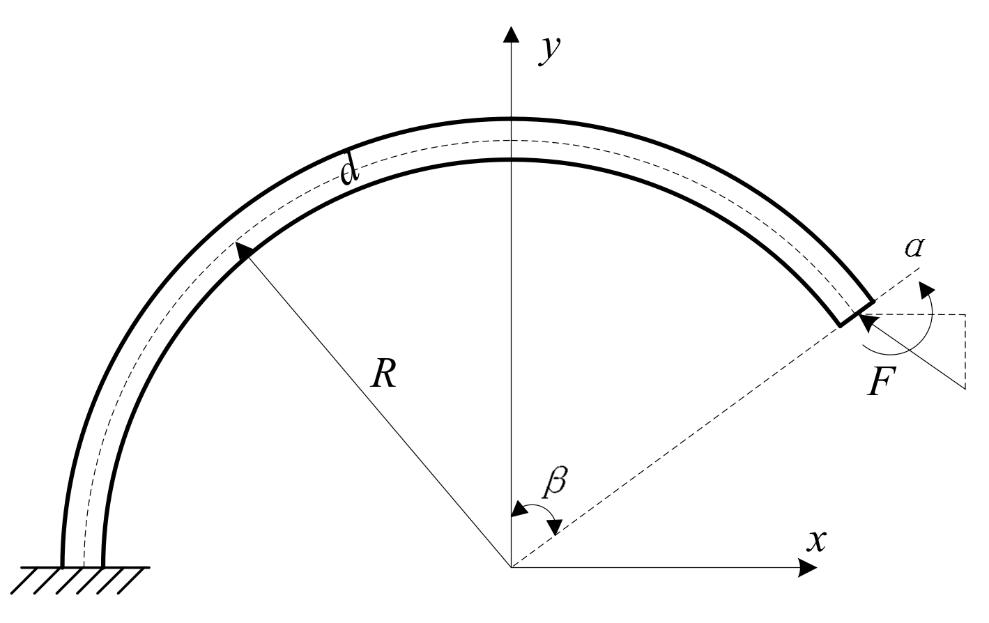
The hook should maintain sufficient strength during the hook–wall surface interaction, which is the basic condition to ensure stable grabbing. The stress model of the hook is equivalent to a bended suspension beam (Figure 3), where is the curvature radius of the hook, is the diameter of the hook section, is the angle of the hook top with the y axis, is the stress on the hook top, and is the rotation angle of the hook top with the z axis under the effect of force .
The following failure forms were concluded in accordance with the interaction mechanism of the hook with bulges on the wall surface:
- (1)
- failure of the bending stress on the hook base;
- (2)
- bending deformation of the hook and separation from micro-bulges; and,
- (3)
- separation induced by the strength deficiency of the micro-bulge.
In the first failure form, the bending stress on the arbitrary section of the hook can be obtained according to the mechanics of the materials. Failure is avoidable as long as the maximum bending stress is less than the allowable stress of the hook and a certain safety factor can be ensured.
In the second failure form, a virtual torque can be added to the beam end when calculating the deflection deformation and rotation deformation on the end of the bending beam, according to Castigliano’s theorem of mechanics of materials. The rotational angle is calculated is as follows:
where is the strain energy of beam, is the elastic coefficient of material, and is a constant.
In the third failure form, failure is generally analyzed through the Hertz stress distribution on the contact point for the surface made of cementitious materials such as concrete and irregular water brush stone. The maximum pressure at the center of the contact point is achieved by the following equations:
where is the material Poisson’s ratio, is the radius of contact spot, is the positive pressure acting on the contact point of the hook and the microbulge, and subscripts and represent the hook top and the microbulge on wall surfaces, respectively.
The maximum tensile stress occurs at the edge of the contact spots, i.e.,
Failure depends on the local strain condition, fracture number, and fracture toughness. The positive pressure on the contact spot is the function of the maximum positive stress.
where the part in the square brackets is constant depending on the properties of the material. Therefore, the maximum tolerable load is determined by the hook top size and the square of the curvature radius of the micro-bulges on the surface.
3.3. Calculation of Supporting Shaft Size
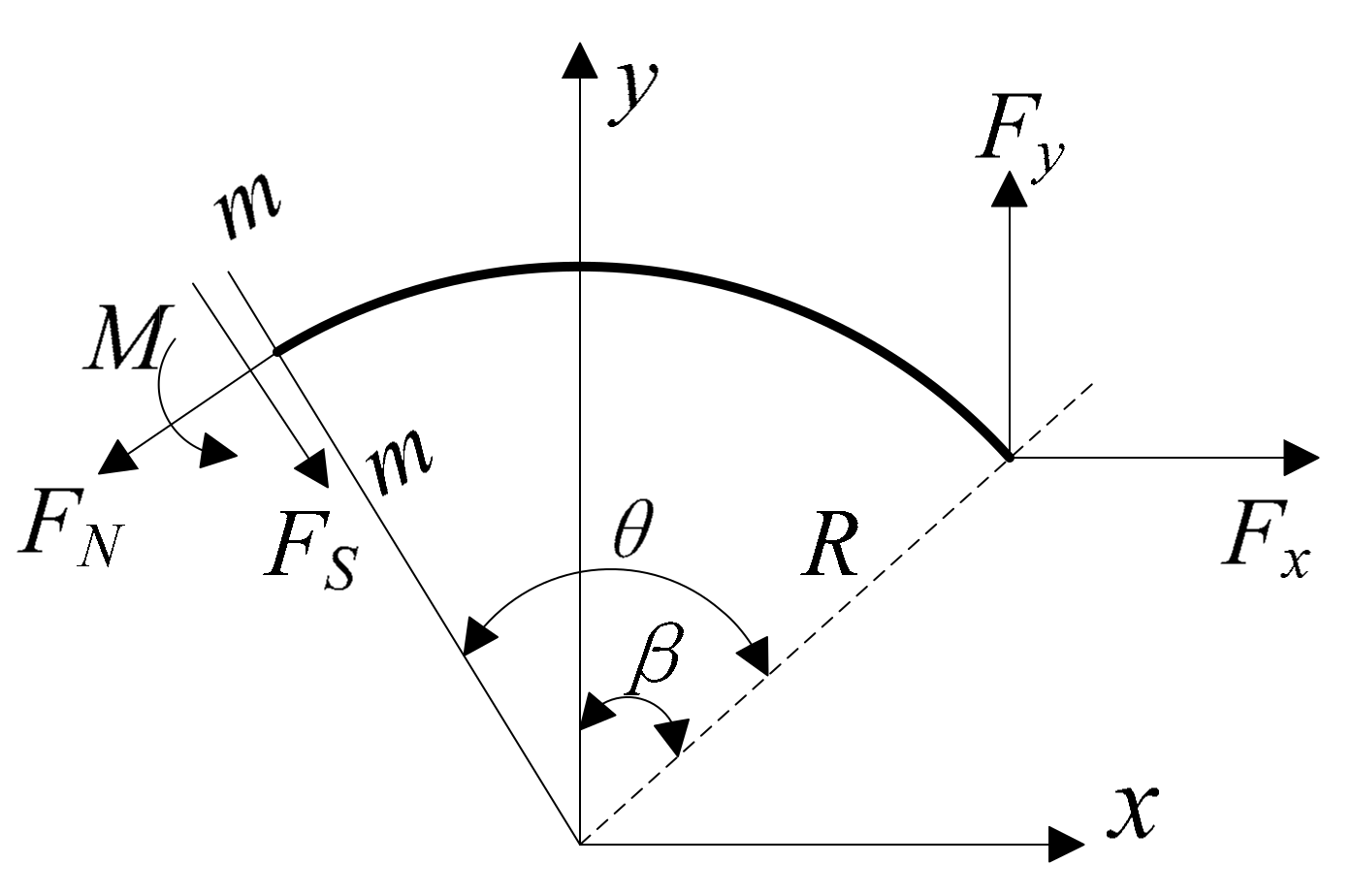
We should calculate the supporting shaft of the hook to determine the cross-sectional diameter of the hook shaft and satisfy the requirements of bending stress. The internal forces on the cross-sectional generally contain moment , shear force , and axial force during the bending deformation of the hook. We used the section method to analyze the stresses on the curved hook. The curved bars were divided into two parts by the cross-sectional (radial section) , with an angle with a hook top. Stresses on curved bar of hook using section method are illustrated in Figure 4.
Stressing analysis of section shows that
where and . are the hook number on a single claw.
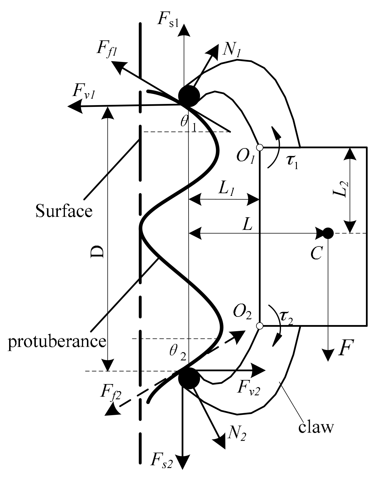
For the whole grasping claw, the claw with minimum hooks (such as two hooks arranged on the upper and lower limbs) is taken as an example to examine the interactions between the grasping claws and the wall surface. Figure 5 shows the forces exerting on the hooked claw by the climbing models constructed in the previous section. are the dimensions of the claw. The direction of friction on the lower claw tip is directly related to the torque magnitude of the torsional spring. When , points downward along the tangent plane of the micro-protuberance. When , points upward along the tangent plane of the micro-protuberance. When , . In this study, is the critical value of the torque of torsional spring.
The angles of the upper and lower micro-protuberances are set to be equal to simplify the problem; that is, , and for the upper claw. Thus, . Therefore, the angles of micro-protuberances must be smaller than the self-locking angle between the claw tip and the micro-protuberance, i.e., . Otherwise, the upper claw slides away and does not grasp the micro-protuberances steadily.
In Figure 5, and are the support force and friction exerted on the upper claw tip by the micro-protuberance, respectively; and are the tangential and normal forces along the wall surface of the support force and friction exerted on the upper claw tip, respectively; and are the support force and friction exerted by the micro-protuberance on the lower claw tip, respectively; and, and are the tangential and normal forces along the wall surface of the support force and friction exerted on the lower claw tip, respectively. is the mass center of the whole hooked claw; and are the torques of torsional spring for the upper and lower hooked claws, respectively; and are the angles of the upper and lower micro-protuberances, respectively; and, G is the gravity of the claw.
Therefore, the normal and tangential forces of the hook along the wall surface are directly correlated with the torque of the coiling spring. The following equations are obtained, according to Equations (1)–(5):
In Equation (6), , , and . Figure 6 shows the relationship between the maximum bending stress of the hook and the hook shaft diameter. The hook was made of 45 steel and was subjected to modulation processing. The top was unitized to increase wear resistance. The diameter of the hook neck shaft was set as by comprehensively considering the influences of strength, stiffness, and safety.
4. Analysis of the Grasping Claws Module Based on ANSYS Workbench
4.1. Secondary Claws
An analysis of the claw structure of reptiles revealed that the claws need to meet the following requirements: (1) loading forces applied on hook tips are reasonably distributed to prevent failure of elastic joints caused by stress concentration; and, (2) multiple hooks are independent. That is, while slipping on a rough wall surface, if a hook grasps a protuberance on the wall and forms mechanical interlocking, other hooks can still search regions that can be grasped along the slipping direction.
In order to analyze whether the design of the elastic claws meets the above requirements and verify the operating safety of the hooks, Solidworks was adopted for modeling, and the model was simplified according to the actual demand (Figure 7). After being imported in the ANSYS Workbench for mesh generation (Figure 8), nodes and elements were attained. The properties of the materials that were used for producing the claws are listed in Table 1.
The connecting plate was fabricated with steel with large yield strength, while the hooks were manufactured with #45 steel. When the two pairs of tiny hooks were mechanically interlocked with the wall surface, the hooks and the elastic steel sheets were deformed and the resulting grasping force pointed to the interior of the wall surface. Suppose that the mass of the grasping module of the claws was 0.5 kg, then 5 N pointing to the interior of the wall and vertical to the tips hooks was applied to the claws in each simulation.
The simulation results are shown in Figure 9.
Figure 9a illustrates the displacement when a hook detaches from the wall surface, while the other hooks the wall. The largest displacement (0.82302 mm) was found at the tip hook. Figure 9b demonstrates the displacement when each of the pair of hooks bears 2.5 N. Under this condition, the largest displacement was found to be 0.82527 mm at the tip of the hooks. It can be seen from Figure 9a,b that the displacement of the other pair of tiny hooks was 0. It indicates that even though a pair of hooks grasp the wall, the other pair of hooks can still search positions that can be grasped along the slipping direction.
Figure 9c shows the displacement when the four hooks of two pairs of claws grip the wall. The displacement of the hooks was 0.41203 mm. The displacement under the condition that one pair of the hooks bear 3.75 N, while the other pair is subjected to 1.25 N, as illustrated in Figure 9d. The largest displacement ( mm) was observed at the tip hook that bore 3.75 N. The above two conditions reveal that, when the two pairs of tiny hooks simultaneously hook the wall, they are independent and not affected by each other.
4.2. Modal Analysis of the Grasping Claws Module
In order to analyze the vibration characteristics of the grasping claws module and provide the theoretical basis for fault diagnosis and optimal design, this section investigated the modal of the grasping claws module.
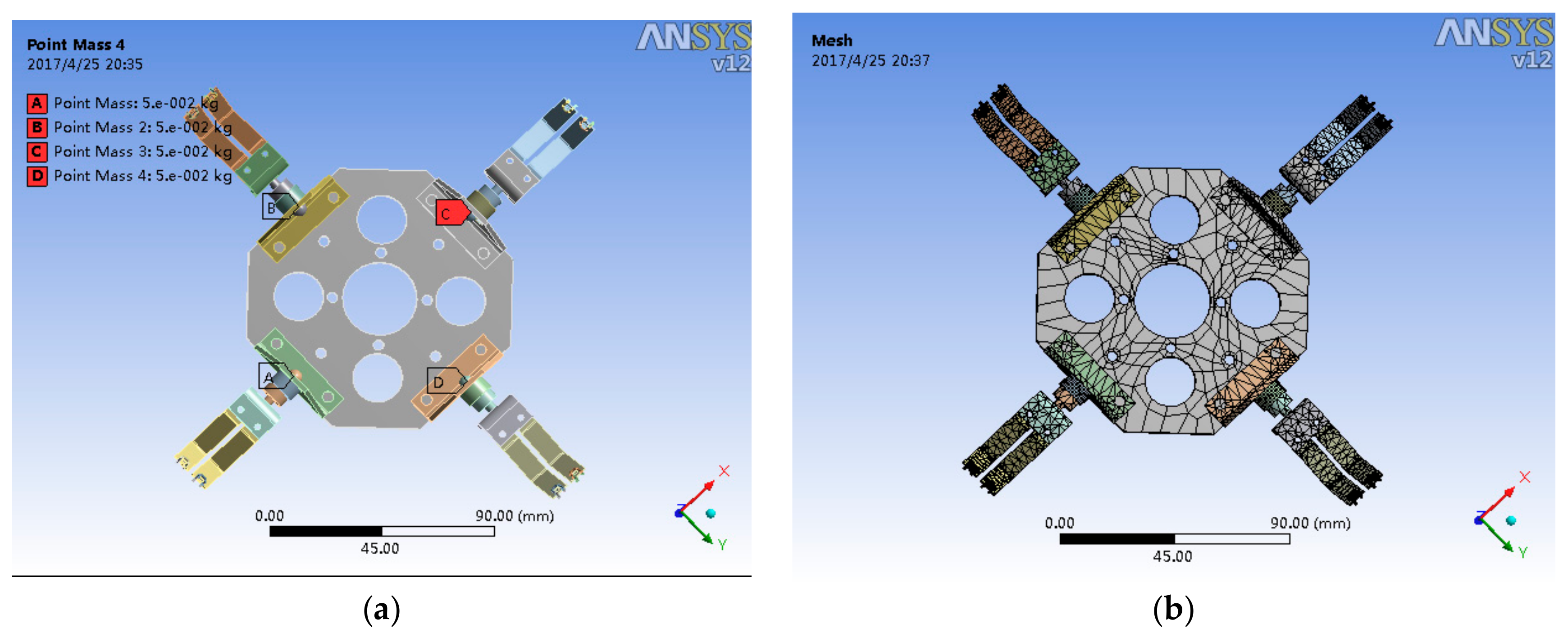
At first, the claws are modeled and simplified by (1) eliminating small holes having little influences on the whole structure, and (2) using the lumped mass to replace the cylinder. According to the material properties in Table 1, constraints are applied to the fixture screw thread and the tips of the hooks. Then, mesh generation was carried out (shown in Figure 10).
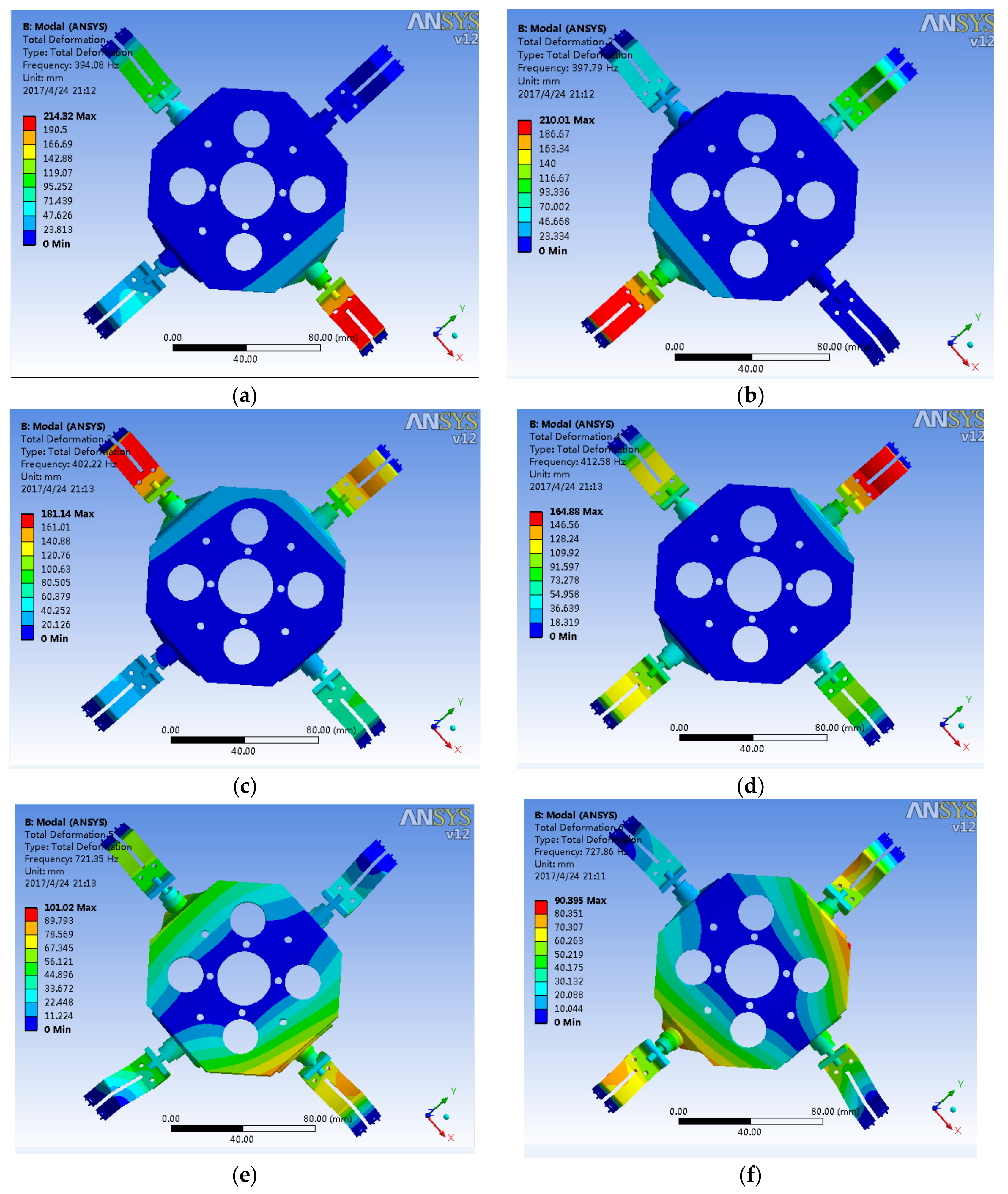
Based on the design of the pre-processing module, loads were applied for solution. The first six orders of modal were set and solved in the solution item max models to find, and the total deformation was inserted into each order of modal. Through solution, the vibration modes and natural frequencies of the first six orders of the grasping module were obtained. The cloud pictures of the displacement are illustrated in Figure 11.
The analysis from Figure 11 reveals that:
The natural frequencies of the first six orders of the grasping claws module mainly range from to . Among them, the natural frequencies of first four orders are close to each other, and those of the last two orders are approximate.
The vibration modes of the first four orders are all the upward and downward flexural vibrations of the corresponding secondary claws and the corresponding hooks have larger amplitudes, while the central part is stable. The vibration modes of the fifth and sixth orders are the folded vibrations of the two ends of the main body, with obvious amplitudes.
When the external exciting frequency approaches the natural frequency in Figure 8, it is likely to incur the resonance of the grasping claws module, leading to large amplitudes, and finally damaging the grasping claws module.
5. Experiments of Bionic Robot
We propose the climbing model of the bionic robot and design a simple prototype. On this basis, the climbing condition of the micro-hook is investigated experimentally.
5.1. Grasping Claws Module Structure
According to the results of finite element analysis in Section 4.2, #45 steel was used to produce the hooks, and the tips were subjected to nitriding treatment to enhance the wear resistance. The elastic steel sheets made of 65 Mn steel underwent surface finish and the holes were smoothed to avoid stress concentration. The main body was manufactured with aluminum alloy. The mechanism is illustrated in Figure 12.
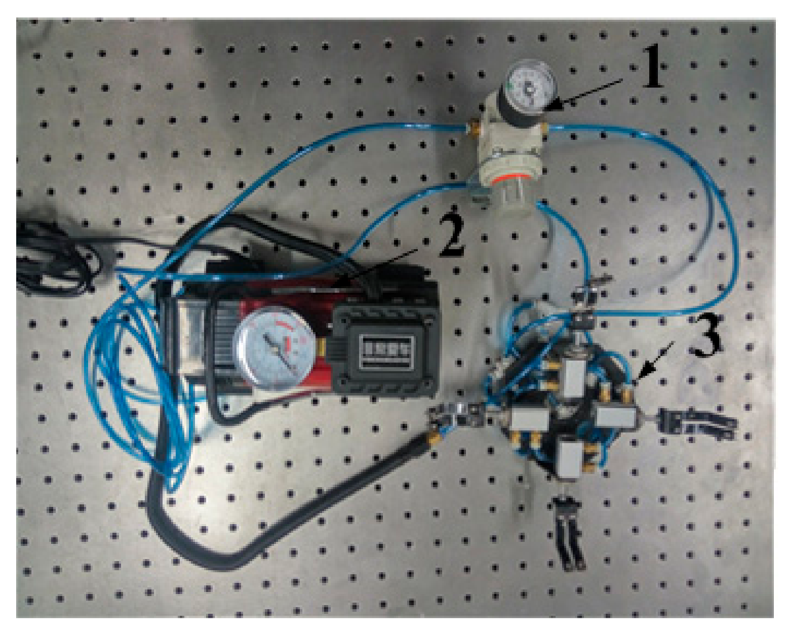
According to the results of modal analysis of claws, the natural frequencies of the grasping claws module are and , so these frequency bands need to be avoided during the simulation experiment. The experiment utilized a vehicle mounted pump as the power source, which was connected with each actuating cylinder through a pneumatic circuit of hoses. A pressure control valve was installed between the actuating cylinder of the secondary claws and the vehicle mounted pump. The pressure inside the cylinder and the driving force can be controlled by adjusting the pressure control valve. So, in the experiment, the pressure control valve mainly played its role according to turning on or off the driving force. During the operation of the vehicle mounted pump, the atmospheric pressure inside the cylinder of the grasping module can be quickly reduced by unplugging the quick connector in one side of the pressure control valve. The total mass of the grasping module of the claws was 431 g. The maximum stroke of the cylinder was 1.75 cm, which proves that the claw can search the grasping rough wall surface in this scope. During the normal work of the vehicle mounted pump in the experiment, the driving force applied by the cylinder to the spiny feet was about 12.7 N.
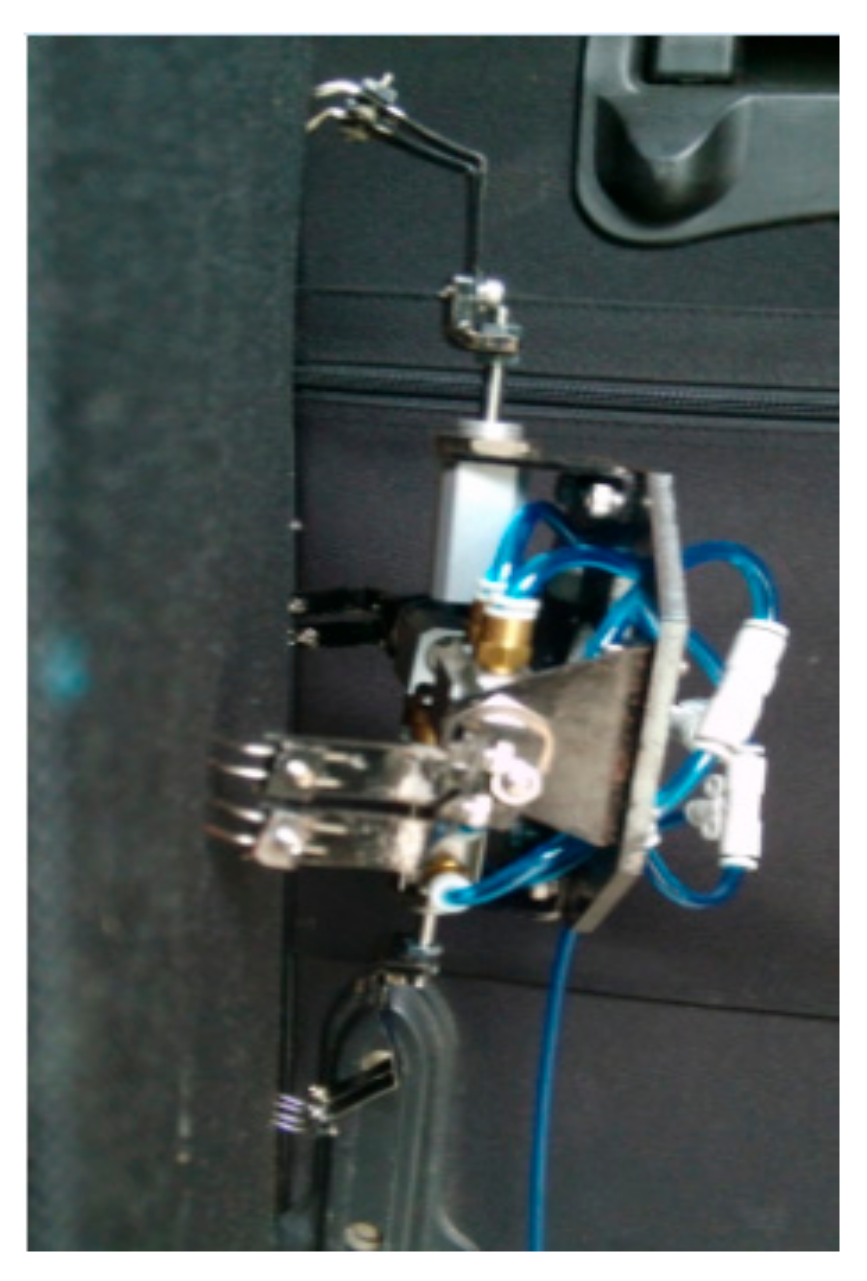
Figure 13 shows the grabbing states of the grasping claws and the working conditions of each spiny foot during the experiment. In the experiment, when the claws contact the wall, the spiny feet had slight reciprocating vibrations in the direction vertical to the wall under the effect of the driving force applied by the connecting rod. Then, the elastic steel sheets were elastically deformed, resulting in the mutual transformation between and the final stabilization of the kinetic energy and elastic potential energy, allowing for the spiny feet to stably hook the rough wall surface. As the spiny feet in the left and the right can also firmly hook and attach onto the rough wall surface, the grasping claws module is able to stably grab the wall when the wall was slightly vibrated.
5.2. Indoor Grabbing Experiments of the Grasping Claws
We carry out the bending experiment for the grasping claws in the laboratory, and verify the strength of single claw, as well as bending property. Moreover, we carry out the vibration experiment to verify the vibration resistance performance of the grabbing method.
(1) Experiment of bending performance for tip claw
In this paper, pneumatic system is used in the innovative mechanism. We carry out some experiments to test whether the pneumatic drive is feasible when the precision in demand is not high. Meanwhile, the new designed pneumatic system can be used with the in-car air pump, so as to carry out some field experiments conveniently.
The grasping process is controlled with a pneumatically driven system to provide adequate grasping force for the robot so it can stably attach to the wall. This method has the advantages of low-energy consumption and low noise. In the laboratory, a test system was established using two types of processed rough walls to perform a grasping test for the designed grippers of the climbing robot. One is the extra rough surface and the other is a random surface. The wall’s dimension (especial the thickness) is too large, which is too heavy to adjust the slanting angles. We also tested the grasping claw on several vertical walls besides the inclined wall. In an effective stroking range of a 1.75 cm air cylinder, if the pressure of 5–10 MPa (it can produce up to 80 N forces on the tiny hook) is controlled and an appropriate angle of the claws are adjusted, then the appropriate uplifts could be found.
The experimental results show that the tip claw is not flexed when sliding on the wall, and there is no obvious deformation and fracture when various forces are applied to the cylinder.
(2) Vibration experiment of the grasping claws
As shown in Figure 14, the grasping claws were attached to the grabbing position. With grabbing force, the claw can withstand the maximum frequency of 12.3 Hz applied through the test platform and the maximum amplitude vibration intensity were 76.2% (1.5875 mm). When without grabbing force, the values were 12.3 Hz, 20.1% (0.41875 mm). The result indicated that the grabbing mode could significantly enhance the vibration resistance performance.
In order to better verify this problem, we divide the claws grabbing experiment with driving force into two stages: the stage of stability grasping when the driving force is applied, and the phase of the removal of the driving force. The transition between two phases is achieved by closing the pressure control valve.
In the experiment, we select output frequency as 12 Hz and intensity as 60% in the vibration platform. For a more intuitive and accurate description of the claw desorption process, we used high-speed camera to capture the image around closing the cylinder, and introduce the image analysis software Image Pro. The experimental results show that the grasp mode has a better vibration resistance performance than the hanging method after the closure of the cylinder.
5.3. Outdoor Grabbing Experiments of the Grasping Claws
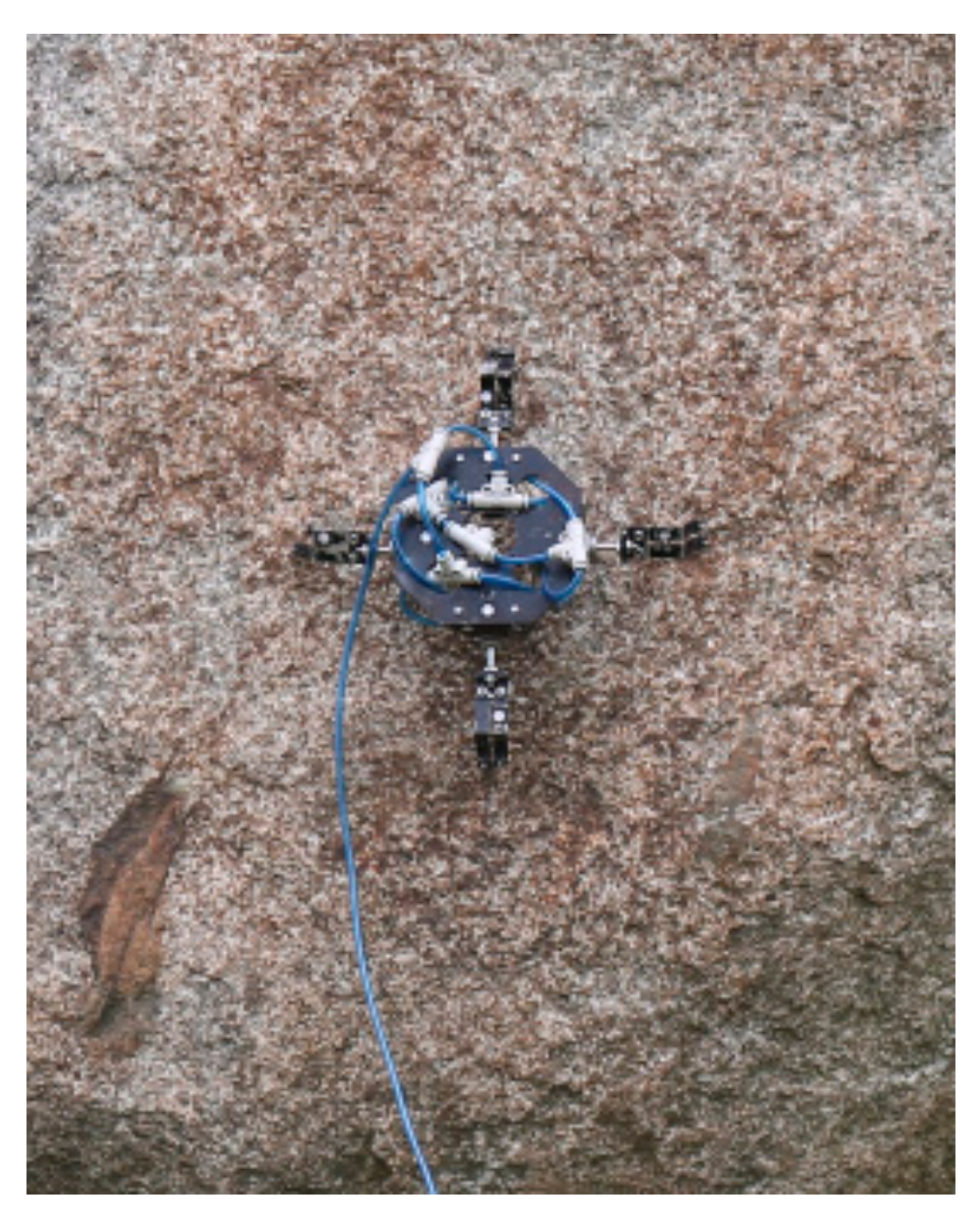
To verify the grabbing ability of the designed mechanism for all kinds of rough wall surfaces, large amounts of outdoor grasping experiments were carried out. Figure 15 shows the grasping claws can achieve stability in the granitic plaster wall. Figure 16 illustrates that the claws can stably grab the rough rock wall. Therefore, the grasping module of cross-arranged claws shows superior robustness against the wall surfaces in the above two cases, indicating that it can work on various rough wall surfaces.
6. Conclusions
Based on the analysis of the grasping mechanism of cockroaches, this paper proposed a bio-inspired compliant spiny feet mechanism, and designed the grasping claws module. By studying the interaction between tiny hooks and rough wall surfaces, the size of miniature hooks was analyzed according to the results of the discriminant algorithm for graspable positions on three-dimensional (3D) rough wall surfaces. Furthermore, the proposed grasping module of the cross-arranged claws was verified based on the grasping model of the claws.
By analyzing the designed mechanism with ANSYS Workbench, the reasonability and reliability of the design of the spiny feet were verified. Meanwhile, the modal of the grasping module of claw was analyzed, which yielded the natural frequencies and vibration modes of the first six orders. On this basis, the authors found that the resonance can be avoided by changing the mass and mass distribution of the grasping claws module. This provides an optimization direction for the overall design of the grasping claws module.
Acknowledgments
This work was supported by the National Natural Science Foundation of China (No. 51775284, 51005025), and Natural Science Foundation of Jiangsu Province (BK20151505, BK20151199). The authors would like to appreciate all the reviewers for their constructive suggestions and comments.
Author Contributions
Quansheng Jiang and Fengyu Xu co-organized the work, designed the experiments, and wrote the paper.
Conflicts of Interest
The authors declare no conflict of interest.
References
- Koo, I.M.; Trong, T.D.; Lee, Y.H.; Moon, H.; Koo, J.; Park, S.K.; Choi, H.R. Development of Wall Climbing Robot System by Using Impeller Type Adhesion Mechanism. J. Intell. Robot. Syst. 2013, 72, 57–72. [Google Scholar] [CrossRef]
- He, B.; Wang, Z.; Li, M. Wet Adhesion Inspired Bionic Climbing Robot. IEEE/ASME Trans. Mechatron. 2014, 19, 312–320. [Google Scholar] [CrossRef]
- Liu, R.; Chen, R.; Shen, H.; Zhang, R. Wall climbing robot using electrostatic adhesion force generated by flexible interdigital electrodes. Int. J. Adv. Robot. Syst. 2013, 10, 1–9. [Google Scholar] [CrossRef]
- Wang, W.; Wang, K.; Zong, G.; Li, D. Principle and experiment of vibrating suction method for wall-climbing robot. Vacuum 2010, 85, 107–112. [Google Scholar] [CrossRef]
- Gao, X.; Xu, D.; Wang, Y. Multifunctional robot to maintain boiler water-cooling tubes. Robotica 2009, 27, 941–948. [Google Scholar] [CrossRef]
- Guo, C.; Sun, J.; Ge, Y.; Wang, W. Biomechanism of Adhesion in Gecko Setae. Chin. Sci. Life Sci. 2012, 42, 135–142. [Google Scholar]
- Bartsch, S.; Birnschein, T.; Rommermann, M.; Hilljegerdes, J.; Kuhn, D. Development of the Six-Legged Walking and Climbing Robot SpaceClimber. J. Field Robot. 2012, 29, 506–532. [Google Scholar] [CrossRef]
- Lam, T.L.; Xu, Y.S. Motion planning for tree climbing with inchworm-like robots. J. Field Robot. 2013, 30, 87–101. [Google Scholar] [CrossRef]
- Asbeck, A.T.; Kim, S.; Cutkosky, M.R.; Provancher, W.R.; Lanzetta, M. Scaling hard vertical surfaces with compliant microspine array. Int. J. Robot. Res. 2006, 25, 1165–1179. [Google Scholar] [CrossRef]
- Sintov, A.; Avramovich, T.; Shapiro, A. Design and motion planning of an autonomous climbing robot with claws. Robot. Auton. Syst. 2011, 59, 1008–1019. [Google Scholar] [CrossRef]
- Parness, A.; Frost, M.; Thatte, N. Gravity-independent Rock-climbing Robot and a Sample Acquisition Tool with Microspine Grippers. J. Field Robot. 2013, 30, 897–915. [Google Scholar] [CrossRef]
- Liu, Y.; Sun, S.; Wu, X.; Mei, T. A Wheeled Wall-Climbing Robot with Bio-Inspired Spine Mechanisms. J. Bion. Eng. 2015, 12, 17–28. [Google Scholar] [CrossRef]
- Guan, Y.; Zhu, H.; Wu, W. A Modular Biped Wall-Climbing Robot with High Mobility and Manipulating Function. IEEE/ASME Trans. Mechatron. 2013, 18, 1787–1798. [Google Scholar] [CrossRef]
- Wang, K.; Gao, W.; Ma, S. Snake-Like Robot with Fusion Gait for High Environmental Adaptability: Design, Modeling, and Experiment. Appl. Sci. 2017, 7, 1133. [Google Scholar] [CrossRef]
- Jiang, L.; Guan, Y.; Cai, C.; Zhu, H. Gait Analysis of a Novel Biomimetic Climbing Robot. J. Mech. Eng. 2010, 46, 17–22. [Google Scholar] [CrossRef]
- Kalind, C.; Nick, W.; Aaron, P. Rotary Microspine Rough Surface Mobility. IEEE/ASME Trans. Mechatron. 2016, 21, 2378–2390. [Google Scholar]
- Arena, P.; Fortuna, L.; Frasca, M. Attitude control in walking hexapod robots: An analogic spatio-temporal approach. Int. J. Circuit Theory Appl. 2002, 30, 349–362. [Google Scholar] [CrossRef]
- Buscarino, A.; Fortuna, L.; Frasca, M.; Muscato, G. Chaos does help motion control. Int. J. Bifurc. Chaos 2007, 17, 3577–3581. [Google Scholar] [CrossRef]
- Buscarino, A.; Fortuna, C.F.L.; Frasca, M. Passive and active vibrations allow self-organization in large-scale electromechanical systems. Int. J. Bifurc. Chaos 2016, 26, 1650123. [Google Scholar] [CrossRef]
- Xu, F.; Wang, X. Design Method and Analysis for Wall-climbing Robot based on Hooked-claws. Int. J. Adv. Robot. Syst. 2012, 9, 1–12. [Google Scholar] [CrossRef]
- Xu, F.; Shen, J.; Hu, J.; Jiang, G. A Rough Concrete Wall Climbing Robot Based on Grasping Claws: Mechanical Design, Analysis and Laboratory Experiments. Int. J. Adv. Robot. Syst. 2016, 13. [Google Scholar] [CrossRef]
- Dai, Z.; Stanislav, N.; Uli, S. Roughness-dependent friction force of the tarsal claw system in the beetle Pachnoda marginata. J. Exp. Biol. 2002, 205, 2479–2488. [Google Scholar] [PubMed]
Figure 1.
The grasping module of cross-arranged claws. 1—Secondary claws, 2—connecting rod, 3—cylinder, 4—main body, 5—fixture screw thread, 6—single tiny hook, 7—crew nut, 8—spring washer, 9—elastic steel sheet, 10—connecting plate, 11—support frame, 12—hose insertion of the cylinder.
Figure 1.
The grasping module of cross-arranged claws. 1—Secondary claws, 2—connecting rod, 3—cylinder, 4—main body, 5—fixture screw thread, 6—single tiny hook, 7—crew nut, 8—spring washer, 9—elastic steel sheet, 10—connecting plate, 11—support frame, 12—hose insertion of the cylinder.

Figure 2.
Microhook.

Figure 3.
Bending beam model of micro-hook.

Figure 4.
Stresses on curved bar of the hook using section method.

Figure 5.
Analysis of stresses on hooked claw.

Figure 6.
Relationship of maximum bending stress of hook with hook shaft diameter.

Figure 7.
Simplified geometric model of the spiny foot.

Figure 8.
Mesh model of the spiny foot.

Figure 9.
Displacement of the spiny feet. (a) Cloud picture for the displacement of a single hook under 5 N; (b) Cloud picture for the displacement of a pair of hooks each bearing 2.5 N; (c) Cloud picture for the displacement of a pair of hooks each bearing 1.25 N; (d) Cloud picture for the displacement of a pair of hooks bearing 3.75 and 1.25 N respectively.

Figure 10.
Finite element models. (a) Finite element model of the grasping claws module; (b) Mesh plot of the grasping claws module.
Figure 10.
Finite element models. (a) Finite element model of the grasping claws module; (b) Mesh plot of the grasping claws module.

Figure 11.
Displacements under vibration modes of the first six orders. (a) Vibration mode of the first order; (b) Vibration mode of the second order; (c) Vibration mode of the third order; (d) Vibration mode of the fourth order; (e) Vibration mode of the fifth order; (f) Vibration mode of the sixth order.

Figure 12.
The grasping claws system prototype. 1—Pressure control valve, 2—vehicle mounted pump, 3—grasping module of the claws.
Figure 12.
The grasping claws system prototype. 1—Pressure control valve, 2—vehicle mounted pump, 3—grasping module of the claws.

Figure 13.
The grabbing posture.

Figure 14.
Indoor grabbing experiments of the grasping claws. (a) Vibration experiment of the grasping claws; (b) The picture of grabbing process.
Figure 14.
Indoor grabbing experiments of the grasping claws. (a) Vibration experiment of the grasping claws; (b) The picture of grabbing process.
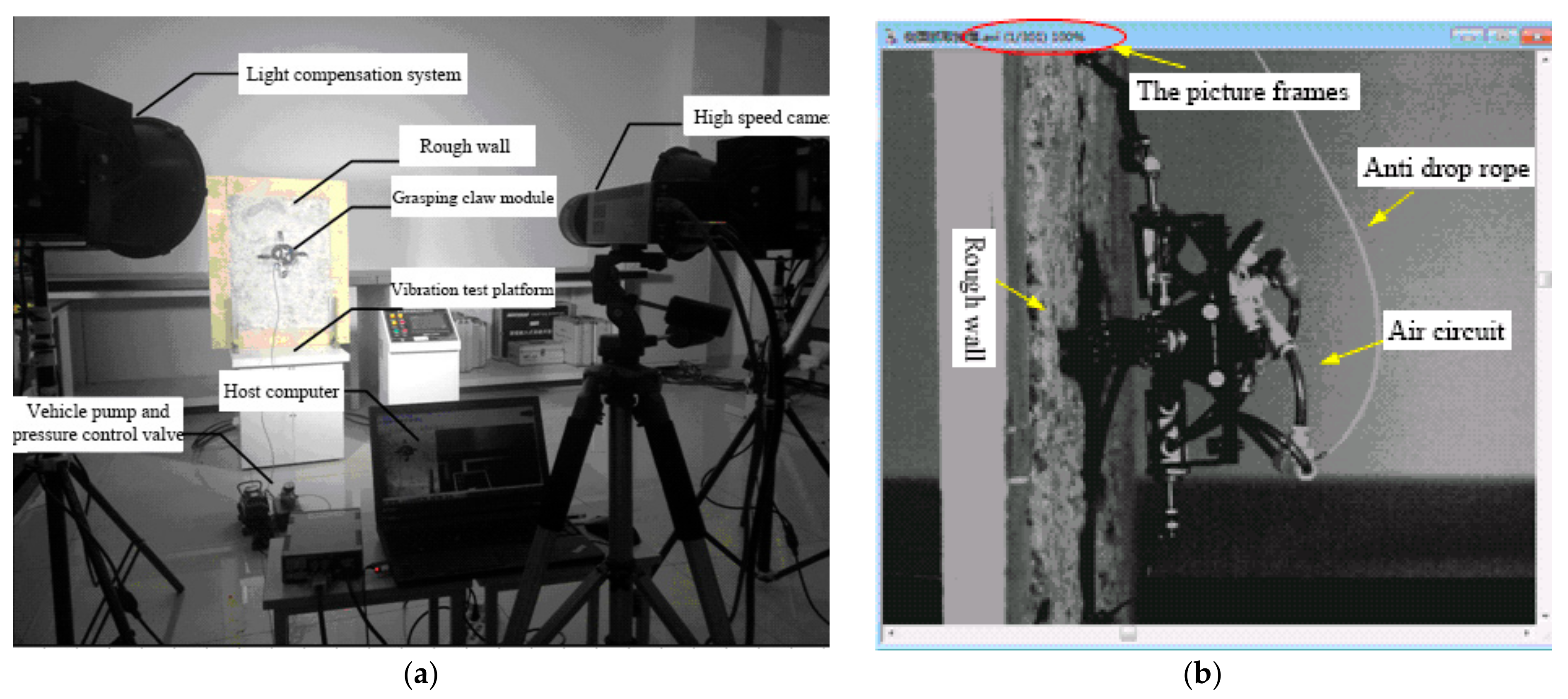
Figure 15.
Stably grabbing the granite wall.
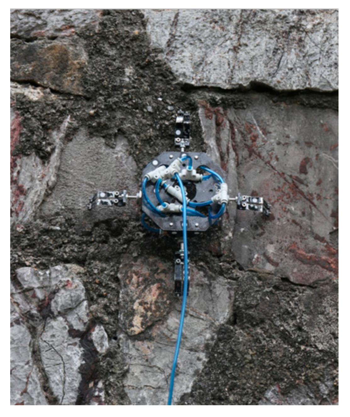
Figure 16.
Stably grabbing the rough rock wall.

Table 1.
Properties of materials used for the grasping claws module.
| Item | Density [kg/m3] | Young’s Modulus [MPa] | Poisson’s Ratio | Yield Strength [MPa] | Tensile Strength [MPa] |
|---|---|---|---|---|---|
| 45# | 7890 | 2 × 10⁵ | 0.3 | 355 | 610 |
| 65 Mn | 7810 | 1.98 × 10⁵ | 0.26 | 784 | 980 |
| Al | 2770 | 7.1 × 10⁴ | 0.33 | 250 | 250 |
© 2017 by the authors. Licensee MDPI, Basel, Switzerland. This article is an open access article distributed under the terms and conditions of the Creative Commons Attribution (CC BY) license (http://creativecommons.org/licenses/by/4.0/).
Share and Cite
MDPI and ACS Style
Jiang, Q.; Xu, F. Grasping Claws of Bionic Climbing Robot for Rough Wall Surface: Modeling and Analysis. Appl. Sci. 2018, 8, 14. https://doi.org/10.3390/app8010014
AMA Style
Jiang Q, Xu F. Grasping Claws of Bionic Climbing Robot for Rough Wall Surface: Modeling and Analysis. Applied Sciences. 2018; 8(1):14. https://doi.org/10.3390/app8010014
Chicago/Turabian StyleJiang, Quansheng, and Fengyu Xu. 2018. "Grasping Claws of Bionic Climbing Robot for Rough Wall Surface: Modeling and Analysis" Applied Sciences 8, no. 1: 14. https://doi.org/10.3390/app8010014
Note that from the first issue of 2016, this journal uses article numbers instead of page numbers. See further details here.