TFR: A Novel Approach for Clock Synchronization Fault Recovery in Precision Time Protocol (PTP) Networks


Abstract
:1. Introduction
2. The Standard PTP
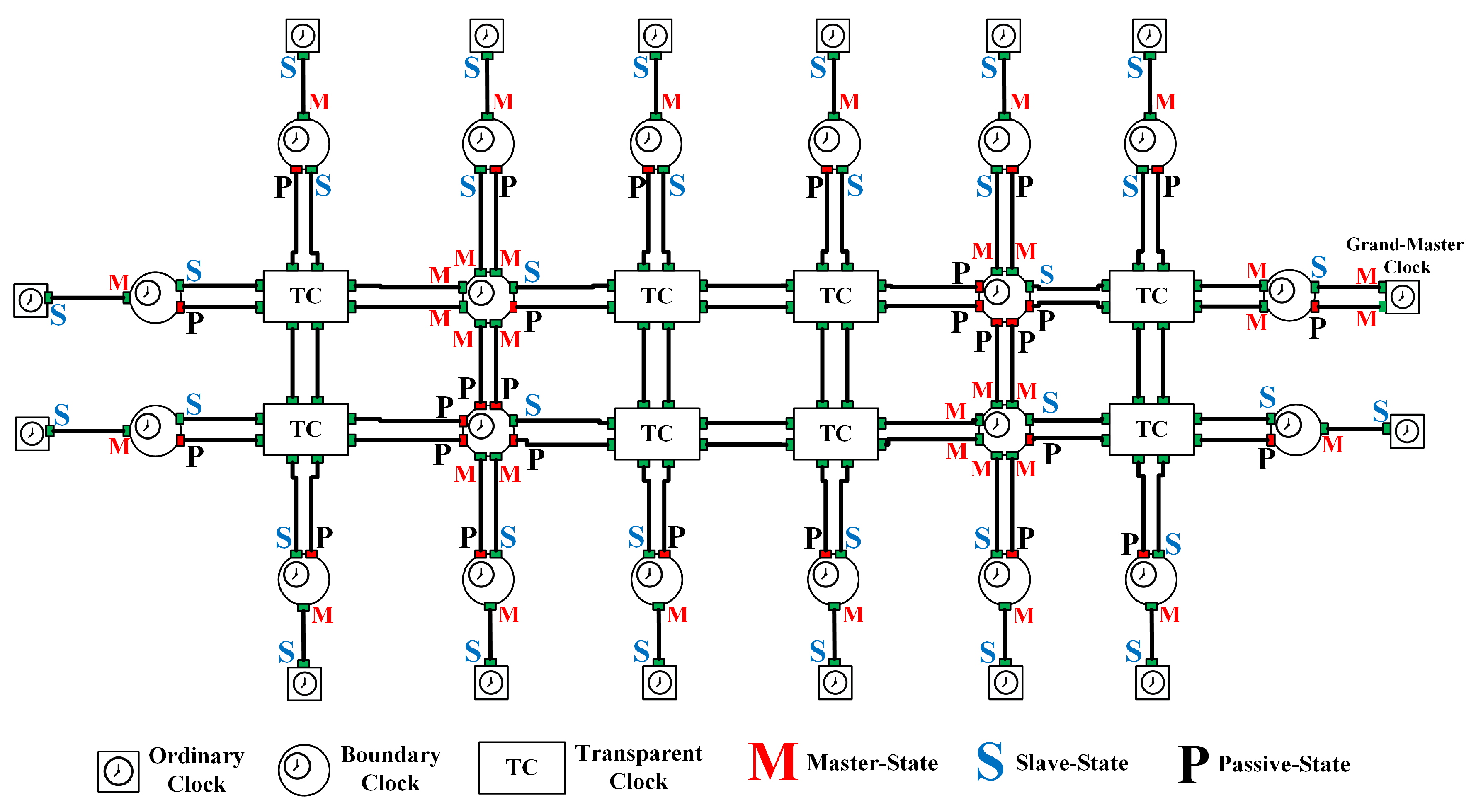
2.1. PTP Operation
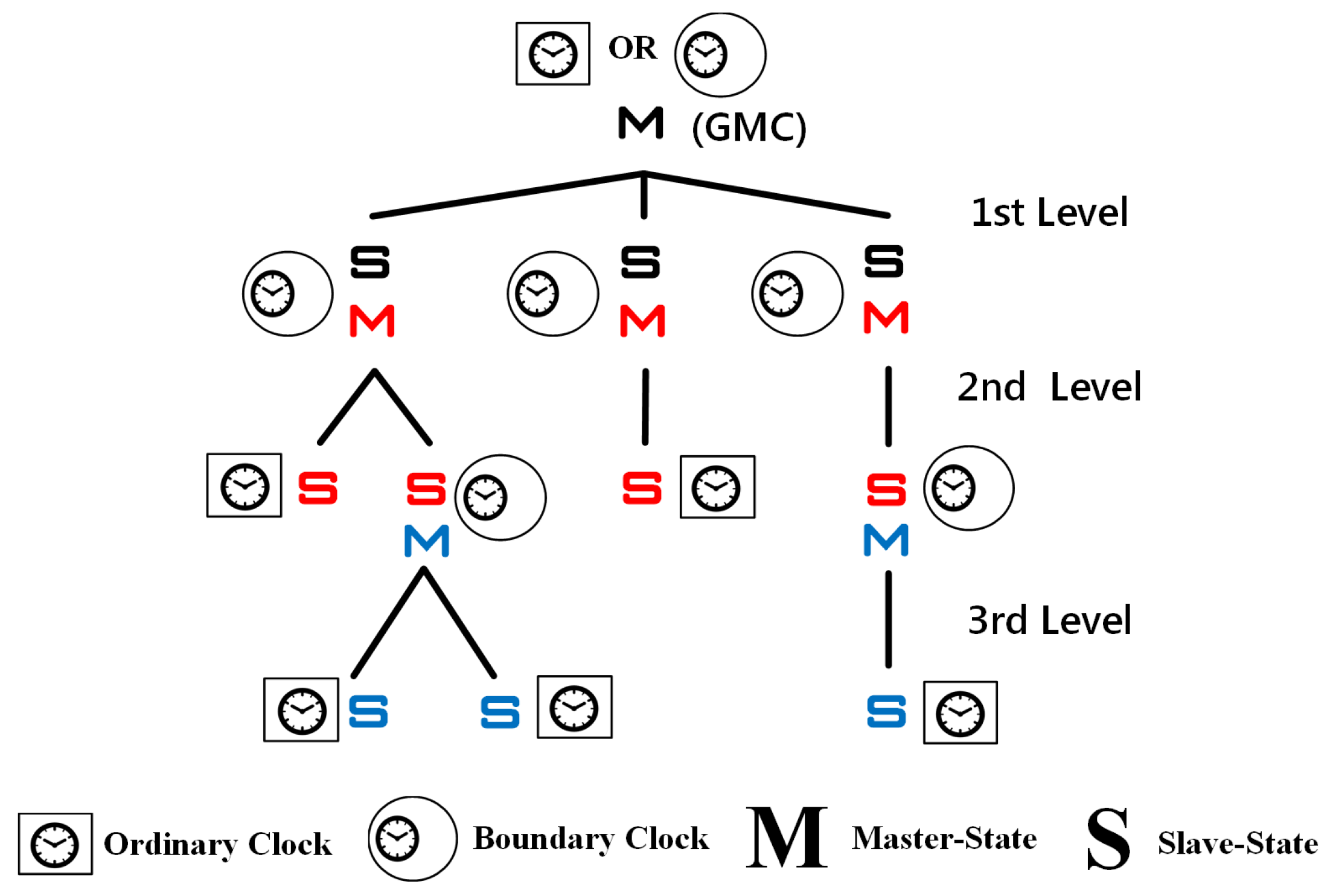
- Ordinary Clock (OC): a clock that has one PTP port in a single domain and that maintains the timescale used in the domain. It may serve as a source of time (i.e., the GMC) or it may synchronize to another clock (i.e., an SC).
- Boundary Clock (BC): a clock that has multiple PTP ports in a single domain or multiple domains and that maintains the timescale used in the domain. It may serve as the source of time (i.e., an MC) and it may synchronize to another clock (i.e., an SC).
- Transparent Clock (TC): a clock that measures and calculates the elapsing time (called the residence time) for PTP event messages, including measurement of the processing and queuing delays. Furthermore, TC measures and calculates the link-propagation delay between similarly equipped ports at the end of the communication path.
2.1.1. Establishing the Master–Slave Synchronization Hierarchy
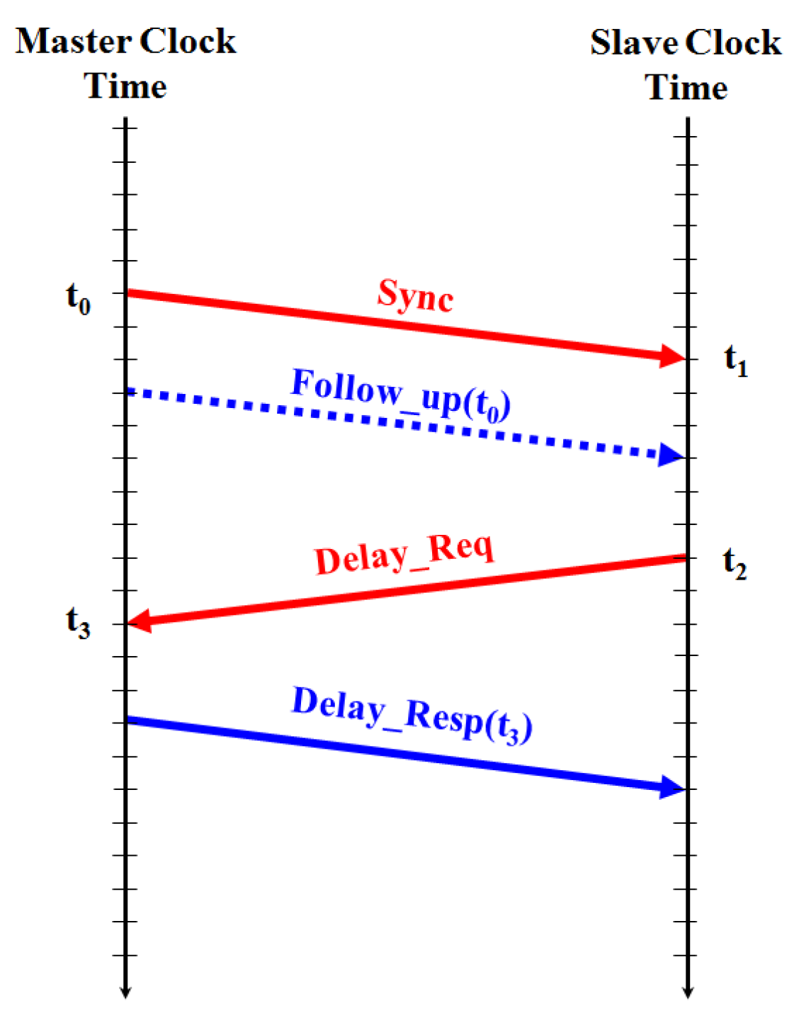
2.1.2. Timing-Exchange Mechanism
2.2. PTP Issues
3. Proposed TFR Approach
3.1. Concepts
- Link-Alive timer: a timer for counting the number of Sync-Intervals that have to pass without receiving Sync messages from the MC. Specifically, the timeout duration is equal to 3 × Sync-Interval.
- Announce timer: a timer for counting the number of Announce-Intervals that have to pass without receiving Announce messages from the MC. Specifically, the timeout duration is equal to 3 × Announce-Interval.
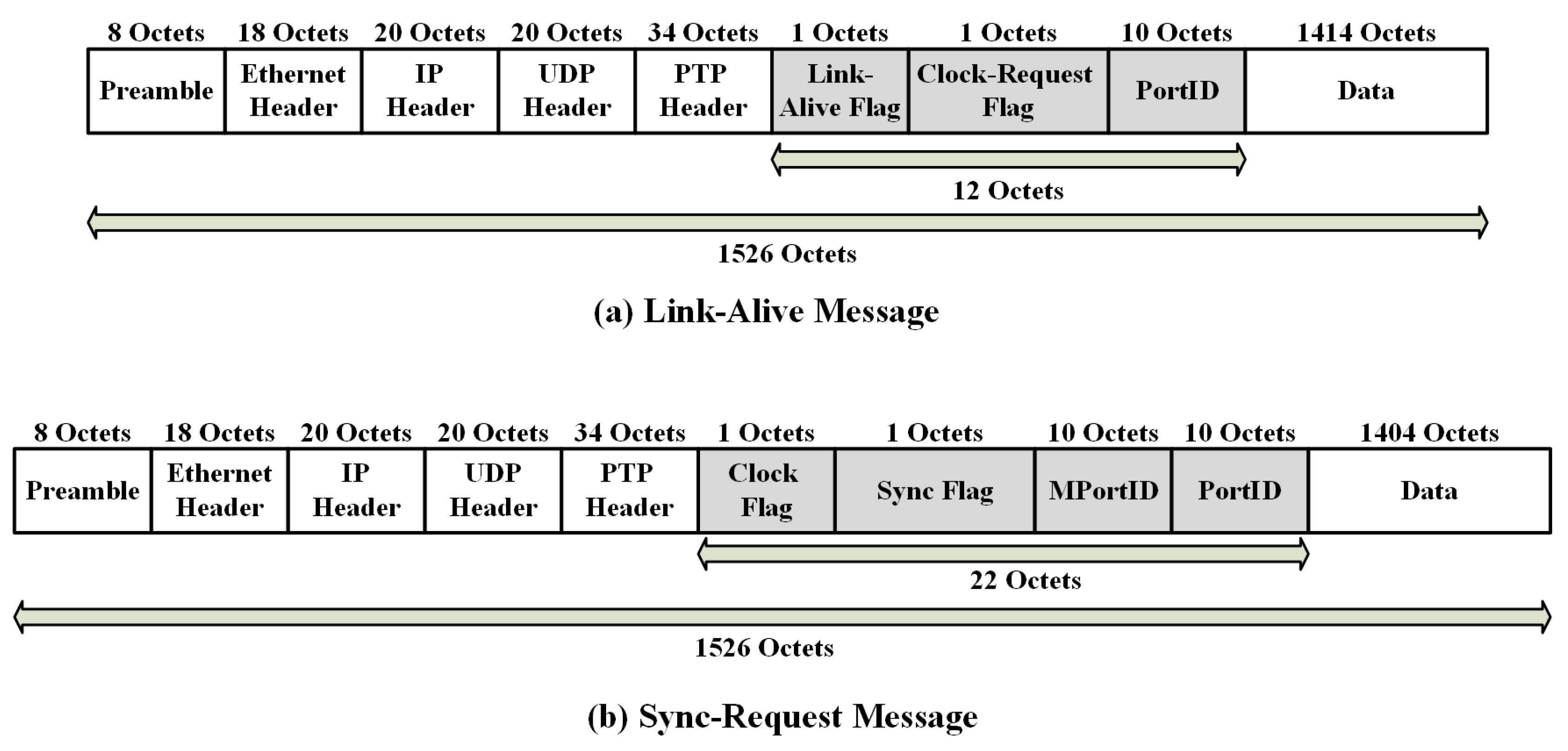
- Link-Alive message: a message that has been used to recover a failure in the network by using specific information inside the message. This message is used to identify a failure in the network of an SC.
- Sync-Request message: a message that has been used to acknowledge the recovery mechanism by the slave nodes after detecting a failure in the network using specific information inside this message.
3.2. Operations
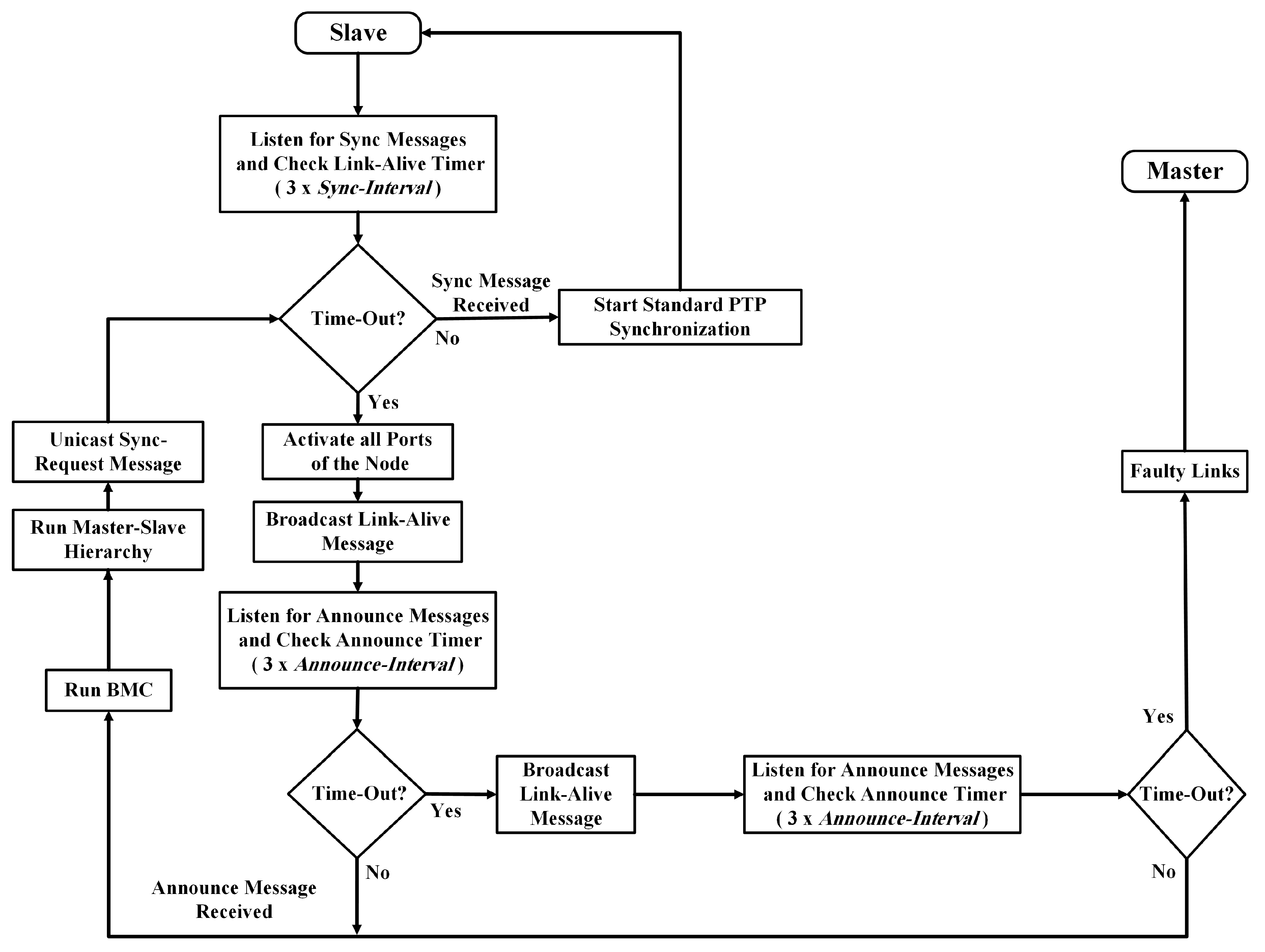
3.2.1. Detecting the Fault Occurrence
- Link-Alive flag: identifies the port state of the transmitting node as either a slave port (flag = 1) or a master port (flag = 0).
- Clock-Request flag: identifies the port of the transmitting node requesting clock synchronization (flag = 1).
- PortID: identifies the port identifier of the transmitting node (slave port).
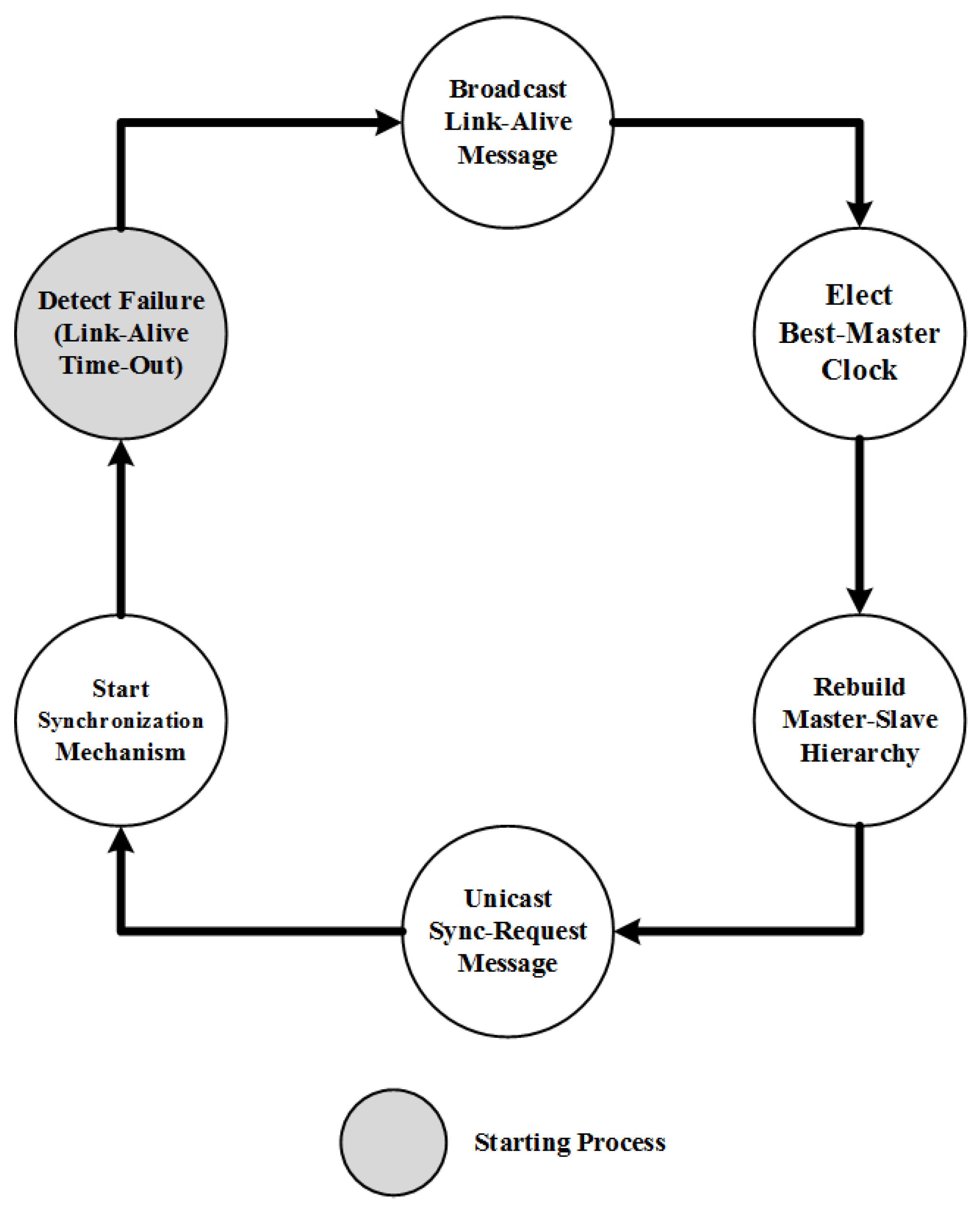
3.2.2. Re-establishing the Synchronization Hierarchy
3.2.3. Fault Recovery Acknowledgement
- Clock flag: identifies the port state of the transmitting node as either a slave port (flag = 1) or a master port (flag = 0).
- Sync flag: identifies the port of the transmitting node that is requesting to start the clock synchronization mechanism immediately (flag = 1).
- PortID: identifies the port identifier of the transmitting node (slave port).
- MPortID: identifies the port identifier of the receipt node (master port).
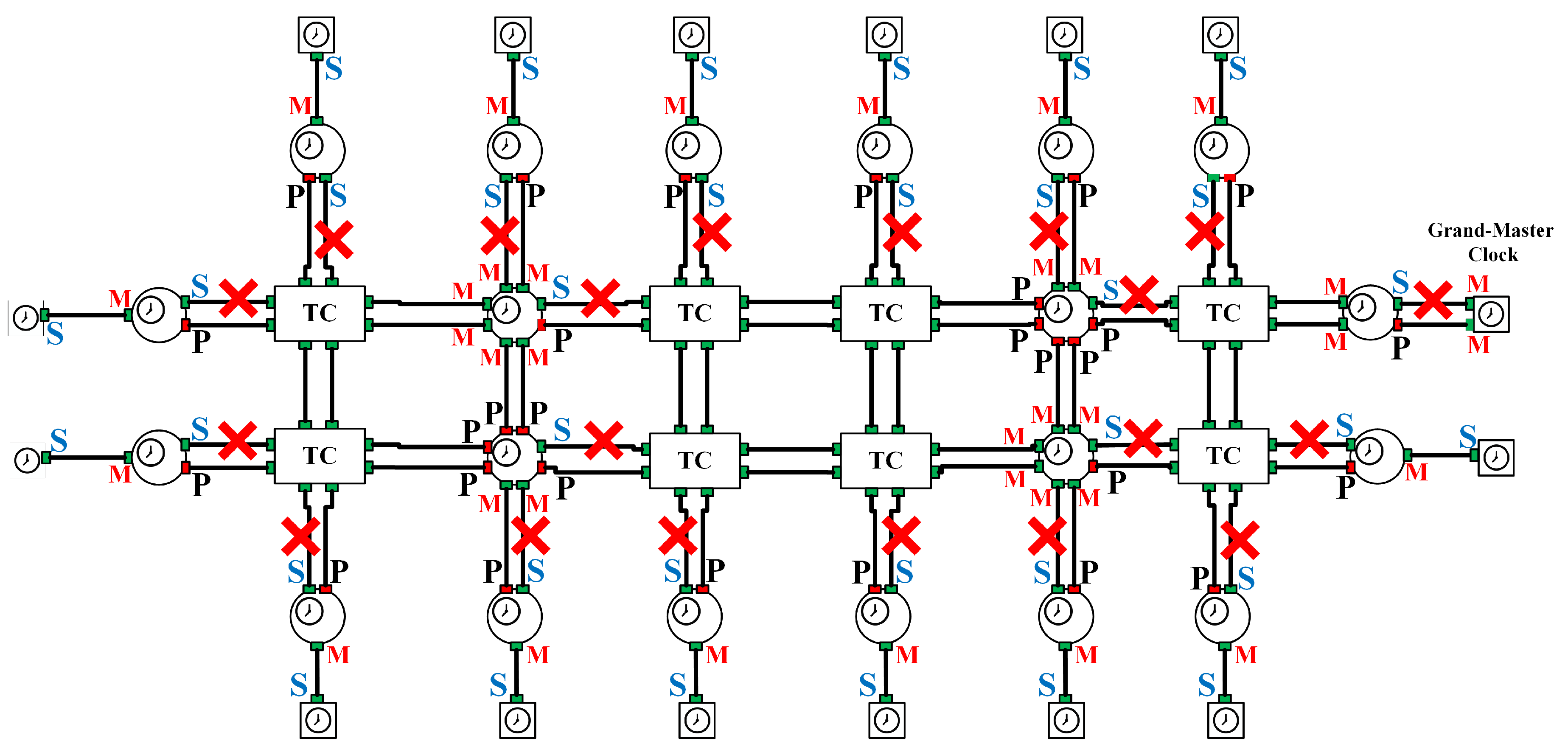
3.2.4. Repairing the Fault Recovery Mechanism Failure
- Fault occurrence after broadcasting a Link-Alive message: If a failure occurs after broadcasting a Link-Alive message, the SC starts an Announce timer. If the Announce timer times out, the slave port broadcasts the Link-Alive message once again toward the master and starts waiting for the Announce message from the MC.
- Fault occurrence after broadcasting a Link-Alive message for the second time: If a failure occurs after broadcasting a Link-Alive message for the second time, the SC starts an Announce timer. Consequently, the slave port starts waiting for the Announce message from the MC; if the SC does not receive an Announce message after this duration, it converts the slave port state to an MC state and distributes its local clock in the same network segment.
- Fault occurrence after unicasting a Sync-Request message: If a failure occurs after unicasting the Sync-Request message, the SC starts a Link-Alive timer. If the Link-Alive timer times out, the slave port starts the fault recovery mechanism once again to detect and recover the failure occurrence in the network.
3.3. State Machine and Algorithm
4. Performance Analysis
| Algorithm 1: TFR Algorithm |
 |
4.1. PTP with RSTP
4.2. TFR
5. Simulations
5.1. Simulation Description
5.2. Simulation Results
5.3. Discussion
6. Conclusions
Acknowledgments
Author Contributions
Conflicts of Interest
References
- Mills, D.L. Internet time synchronization: The network time protocol. IEEE Trans. Commun. 1991, 39, 1482–1493. [Google Scholar] [CrossRef]
- Subrahmanyan, R. Implementation considerations for IEEE 1588v2 applications in telecommunications. In Proceedings of the 2007 IEEE International Symposium on Precision Clock Synchronization for Measurement, Control and Communication, Vienna, Austria, 1–3 October 2007; pp. 148–154. [Google Scholar]
- Mills, D.; Martin, J.; Burbank, J.; Kasch, W. Network Time Protocol Version 4: Protocol and Algorithms Specification; Technical Report; Internet Engineering Task Force (IETF): Fremont, CA, USA, 2010. [Google Scholar]
- IEEE Standard for A Precision Clock Synchronization Protocol for Networked Measurement and Control Systems; IEEE Std 1588-2002; IEEE: Piscataway, NJ, USA, 2002; pp. i–144.
- IEEE Standard for A Precision Clock Synchronization Protocol for Networked Measurement and Control Systems; IEEE Std 1588-2008 (Revision of IEEE Std 1588-2002); IEEE: Piscataway, NJ, USA, 2008; pp. 1–300.
- Gaderer, G.; Loschmidt, P.; Sauter, T. Improving fault tolerance in high-precision clock synchronization. IEEE Trans. Ind. Inf. 2010, 6, 206–215. [Google Scholar] [CrossRef]
- Kozakai, Y.; Kanda, M. Keeping clock accuracy on a master clock failure in substation network. In Proceedings of the 2010 IEEE International Symposium on Precision Clock Synchronization for Measurement, Control and Communication (ISPCS), Portsmouth, NH, USA, 27 September–1 October 2010; pp. 25–29. [Google Scholar]
- Murakami, T.; Horiuchi, Y. A master redundancy technique in IEEE 1588 synchronization with a link congestion estimation. In Proceedings of the 2010 IEEE International Symposium on Precision Clock Synchronization for Measurement Control and Communication (ISPCS), Portsmouth, NH, USA, 27 September–1 October 2010; pp. 30–35. [Google Scholar]
- Puhm, A.; Mahmood, A.; Bigler, T.; Kerö, N. Synchronizing an IEEE 1588 slave clock over both paths of a redundant Ethernet system. In Proceedings of the 2016 IEEE International Symposium on Precision Clock Synchronization for Measurement, Control, and Communication (ISPCS), Stockholm, Sweden, 4–9 September 2016; pp. 1–6. [Google Scholar]
- Shpiner, A.; Revah, Y.; Mizrahi, T. Multi-path time protocols. In Proceedings of the 2013 IEEE International Symposium on Precision Clock Synchronization for Measurement Control and Communication (ISPCS), Lemgo, Germany, 22–27 September 2013; pp. 1–6. [Google Scholar]
- Ferrari, P.; Flammini, A.; Rinaldi, S.; Prytz, G. High availability IEEE 1588 nodes over IEEE 802.1aq Shortest Path Bridging networks. In Proceedings of the 2013 IEEE International Symposium on Precision Clock Synchronization for Measurement, Control and Communication (ISPCS), Lemgo, Germany, 22–27 September 2013; pp. 35–40. [Google Scholar]
- TC57. Communication Networks and Systems in Substations Part 90-4: Network Engineering Guidelines; Technical Report; TR 61850-90-4; IEC: Geneva, Switzerland, 2013. [Google Scholar]
- IEEE Standard for Local and Metropolitan Area Networks: Media Access Control (MAC) Bridges; IEEE Std 802.1D-2004 (Revision of IEEE Std 802.1D-1998); IEEE: Piscataway, NJ, USA, 2004; pp. 1–277.
- Prytz, G. Redundancy in industrial Ethernet networks. In Proceedings of the 2006 IEEE International Workshop on Factory Communication Systems, Torino, Italy, 28–30 June 2006; pp. 380–385. [Google Scholar]
- Meier, S.; Weibel, H. IEEE 1588 applied in the environment of high availability LANs. In Proceedings of the IEEE International Symposium on Precision Clock Synchronization for Measurement, Control and Communication (ISPCS), Vienna, Austria, 1–3 October 2007; pp. 100–104. [Google Scholar]
- Precision Time Protocol Telecom Profile for Time/Phase Synchronization with Partial Timing Support From the Network; ITU-T G.8275.2 Recommendation; International Telecommunication Union/ITU Telcommunication Sector: Geneva, Switzerland, 2016; pp. 1–46.
- OMNeT++ Discrete Event Simulator. Version 4.6. Available online: http://www.omnetpp.org/ (accessed on 10 October 2017).


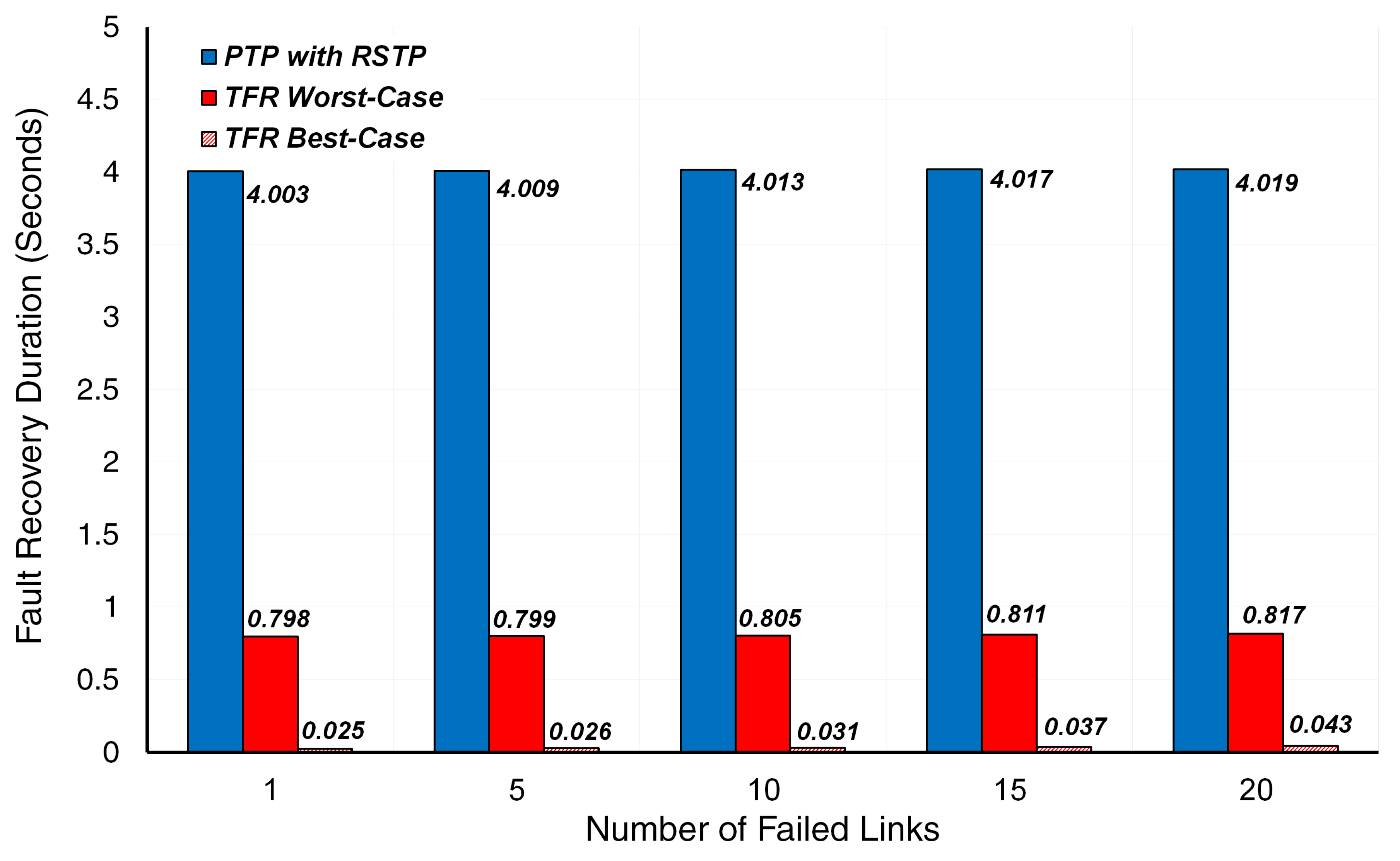
| Number of Failed Links | PTP with RSTP | TFR Best-Case Scenario | TFR Worst-Case Scenario |
|---|---|---|---|
| 1 | 4 | 0.0234 | 0.7969 |
| 2 | 4 | 0.0236 | 0.7970 |
| 3 | 4 | 0.0238 | 0.7972 |
| 4 | 4 | 0.0241 | 0.7975 |
| 5 | 4 | 0.0245 | 0.7979 |
| 6 | 4 | 0.0250 | 0.7984 |
| 7 | 4 | 0.0256 | 0.7990 |
| 8 | 4 | 0.0262 | 0.7997 |
| 9 | 4 | 0.0270 | 0.8004 |
| 10 | 4 | 0.0278 | 0.8012 |
| 11 | 4 | 0.0287 | 0.8022 |
| 12 | 4 | 0.0297 | 0.8032 |
| 13 | 4 | 0.0309 | 0.8043 |
| 14 | 4 | 0.0320 | 0.8055 |
| 15 | 4 | 0.0322 | 0.8068 |
| 16 | 4 | 0.0347 | 0.8081 |
| 17 | 4 | 0.0361 | 0.8096 |
| 18 | 4 | 0.0377 | 0.8111 |
| 19 | 4 | 0.0393 | 0.8128 |
| 20 | 4 | 0.0411 | 0.8145 |
© 2017 by the authors. Licensee MDPI, Basel, Switzerland. This article is an open access article distributed under the terms and conditions of the Creative Commons Attribution (CC BY) license (http://creativecommons.org/licenses/by/4.0/).
Share and Cite
Alshaikhli, A.O.; Rhee, J.M. TFR: A Novel Approach for Clock Synchronization Fault Recovery in Precision Time Protocol (PTP) Networks. Appl. Sci. 2018, 8, 21. https://doi.org/10.3390/app8010021
Alshaikhli AO, Rhee JM. TFR: A Novel Approach for Clock Synchronization Fault Recovery in Precision Time Protocol (PTP) Networks. Applied Sciences. 2018; 8(1):21. https://doi.org/10.3390/app8010021
Chicago/Turabian StyleAlshaikhli, Alfarooq Omar, and Jong Myung Rhee. 2018. "TFR: A Novel Approach for Clock Synchronization Fault Recovery in Precision Time Protocol (PTP) Networks" Applied Sciences 8, no. 1: 21. https://doi.org/10.3390/app8010021
APA StyleAlshaikhli, A. O., & Rhee, J. M. (2018). TFR: A Novel Approach for Clock Synchronization Fault Recovery in Precision Time Protocol (PTP) Networks. Applied Sciences, 8(1), 21. https://doi.org/10.3390/app8010021