Article

Upper-Body Control and Mechanism of Humanoids to Compensate for Angular Momentum in the Yaw Direction Based on Human Running

1
Department of Modern Mechanical Engineering, Waseda University, 2-2 Wakamatsu-cho, Shinjuku-ku, Tokyo 162-8480, Japan
2
Waseda Institute for Advanced Study, Waseda University, No. 41-304, 17 Kikui-cho, Shinjuku-ku, Tokyo 162-0044, Japan
3
Humanoid Robotics Institute (HRI), Waseda University, 2-2 Wakamatsu-cho, Shinjuku-ku, Tokyo 162-8480, Japan
4
Graduate School of Science and Engineering, Waseda University, No. 41-304, 17 Kikui-cho, Shinjuku-ku, Tokyo 162-0044, Japan
5
ASICS Corporation, Institute of Sport Science, 6-2-1 Takatsukadai, Nishi-ku, Kobe, 651-2271, Japan
6
Faculty of Sport Sciences, Waseda University, 2-579-15 Mikajima, Tokorozawa-shi, Tokyo 359-1192, Japan
7
Faculty of Engineering, Kanagawa University, 3-27-1 Rokkakubashi, Kanagawa-ku, Yokohama 221-8686, Japan
*
Author to whom correspondence should be addressed.
These authors contributed equally to this work.
Appl. Sci. 2018, 8(1), 44; https://doi.org/10.3390/app8010044
Submission received: 23 October 2017 / Revised: 25 December 2017 / Accepted: 27 December 2017 / Published: 3 January 2018
(This article belongs to the Special Issue Bio-Inspired Robotics)

Abstract

:
Many extant studies proposed various stabilizing control methods for humanoids during the stance phase while hopping and running. Although these methods contribute to stability during hopping and running, humanoid robots do not swing their legs rapidly during the flight phase to prevent rotation in the yaw direction. Humans utilize their torsos and arms when running to compensate for the angular momentum in the yaw direction generated by leg movement during the flight phase. In this study, we developed an angular momentum control method based on human motion for a humanoid upper body. The method involves calculation of the angular momentum generated by the movement of the humanoid legs and calculation of the torso and arm motions required to compensate for the angular momentum of the legs in the yaw direction. We also developed a humanoid upper-body mechanism having human link length and mass properties, using carbon-fiber-reinforced plastic and a symmetric structure for generating large angular momentum. The humanoid robot developed in this study could generate almost the same angular momentum as that of a human. Furthermore, when suspended in midair, the humanoid robot achieved angular momentum compensation in the yaw direction.

Graphical Abstract

1. Introduction

Humanoid robots are expected to be useful in various environments where people live. The reason for this is that humanoid robots, which are close to humans in behavior and functionality, are easy to adapt to the living environment designed for human beings. In addition, while other robots have only a few controllable joints, humanoid robots have more than 20 joints and can negotiate various scenarios. Locomotion is necessary to work in various situations, and so far, many studies have been performed on stable walking motion generation techniques. In recent years, running, which is a movement mode including the flight phase with a faster moving speed compared to walking, has also attracted attention, and research is being advanced on running motion generation methods to improve the movement ability of a humanoid robot. Raibert et al. developed a running robot with a single linear leg [1]. The bipedal robot ATRIAS has a four-bar leg mechanism that includes a series of elastic springs [2,3]. Hyon et al. developed a biologically inspired robot based on a dog-leg model [4]. However, these robots do not have a human-like structure. Some studies have shown that bipedal humanoid robots can run [5,6,7,8,9]. For example, the Advanced Step in Innovative MObility (ASIMO) humanoid robot, which was designed and developed by Honda, can run at a speed of 2.5 m/s [10]. Toyota’s bipedal humanoid robot can run using a zero-moment-point (ZMP)-based running control system [11]. The athlete robot developed by Niiyama et al. has a human-like musculoskeletal system built to execute dynamic motions, such as running [12]. The bipedal robot MABEL, developed by researchers at the University of Michigan, has leg elasticity that originates from a leaf spring. It is the fastest-running of all currently available bipedal robots, having achieved a speed of 3 m/s with axial constraints on the y-axis [13].
However, present humanoid robots cannot run as fast and stably as human beings, who can run at speeds ranging between 2 m/s and 13 m/s. The reason that ordinary humanoid robots cannot run as fast and stably as humans because they require both a large power output for kicking the ground and various stabilization control methods. In general, to increase the power output, actuators having large power output capacity are required. However, high power actuators are heavy and their use in the humanoid robots renders the robots heavy. Moreover, the actuators require higher power. Therefore, it is difficult to design humanoid robots that can achieve high power output and are light enough to jump. Ordinary humanoid robots can attain a power output of approximately 3.5 W/kg for the joints in the leg; however, humans generate around 16.7 W/kg in leg joints while running [14]. In addition, various stabilization control methods such as considering the center of mass position, landing point, ground reaction force, and linear and angular momentum, are needed for stable running. However, present running stabilization methods do not consider motion during the flight phase. For example, several studies on running control have used the spring-loaded inverted pendulum (SLIP) model [15,16,17]. This simple model does not consider the mass of the legs, which generates angular momentum by leg swinging [18]. However, a humanoid that can perform human-like fast lower-leg swinging, generates large angular momentum during the flight phase, especially in the yaw direction. Some studies considered the angular momentum of the entire body; however, they focused mainly on only stance-phase movement [19,20]. Thus, in these studies, humanoids could run slowly without leg swing during the flight phase to decrease the angular momentum generated by leg motion. Therefore, the humanoid requires a method to compensate for angular momentum during the flight phase for high speed running.
For fast and stable running, various characteristics of human running have been identified in studies on human sciences and sport sciences, including the following:
  • The stance leg acts like a linear spring. A human leg can be modeled as a SLIP model.
  • The knee and ankle joints in the stance leg serve as torsion springs that provide leg elasticity and the ability to kick the ground strongly [21,22].
  • The leg and joint stiffness change depending on the running speed [23].
  • Rapid knee bending occurs in the swing phase to avoid contact of the foot with the ground [24].
  • The pelvis rotates in the frontal plane to increase the jumping force [25].
  • Moment compensation is accomplished using torso and arm swinging in yaw direction [26,27].
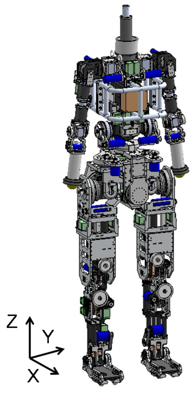
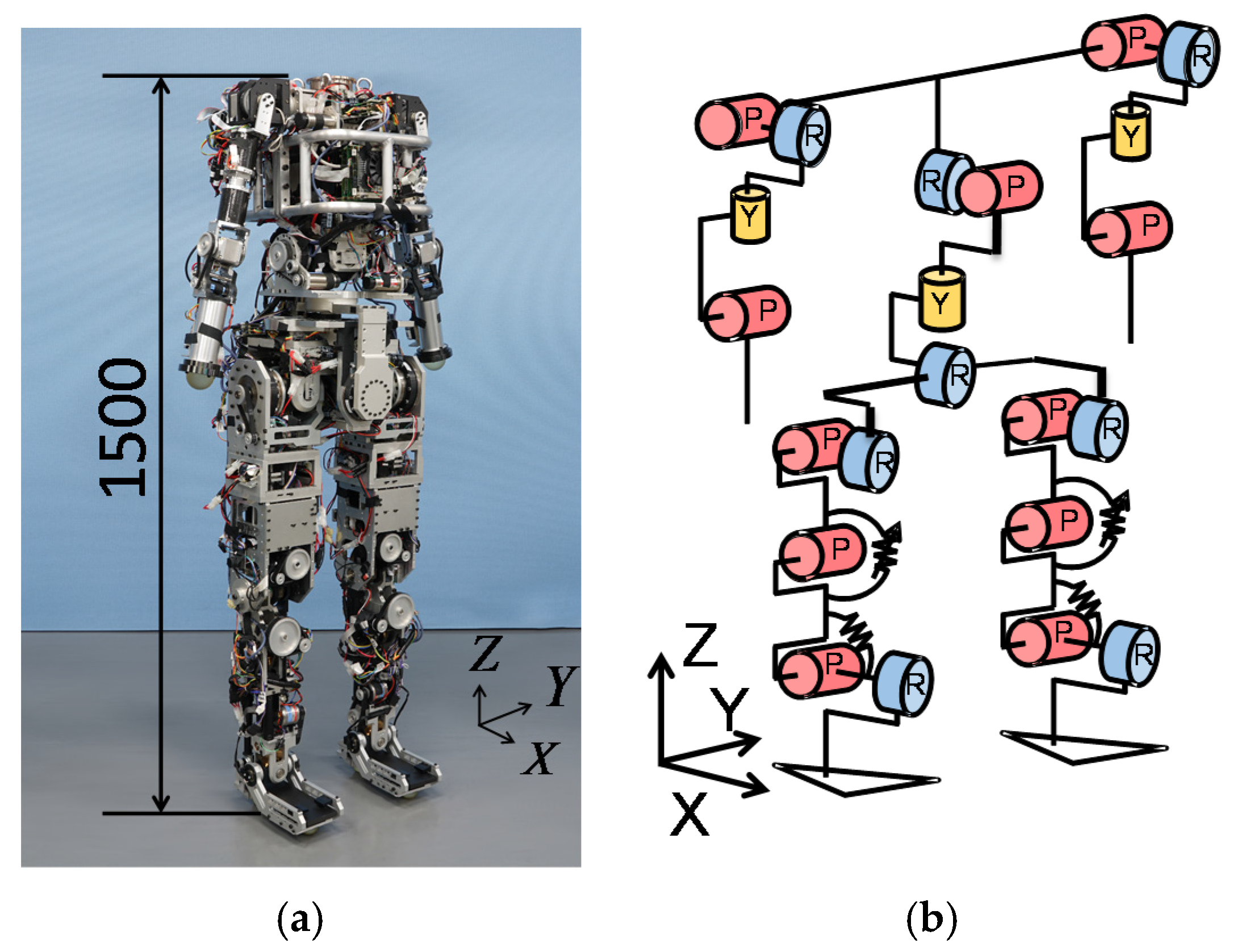
We are working to develop a robot that can run like a human by mimicking the above characteristics. Previously, we developed a lower-body robot that mimics human characteristics, such as leg joint stiffness and pelvic rotations in the frontal plane and can hop with a large joint output of approximately 1000 W by not dissipating the energy at landing but storing the energy in its elastic parts [25,28,29]. In addition, the lower-body robot has the human link length and mass properties, such as the mass, center-of-mass (COM) position in the link, and inertial matrix of each link. The reason for this is that link length and mass properties would result in angular momentum. The currently available humanoid robots do not have human like link lengths or mass properties. These humanoid robots are presumed to have been developed with a focus on walking, which is a movement slower than running. When the angular velocities of joints are not very large, the angular momentum generated is not large and has little influence on the whole-body motion. Some researchers are interested in methods of generating stable motion during the stance phase. Sugihara et al. are developing stable control based on the momentum as a norm during walking exercises [30]. Hyon et al. investigated a back-handspring motion with a multi-link robot and proposed motion planning considering global physical quantities such as the center of mass or angular momentum during the stance phase [31]. On the other hand, during the flight phase, the angular momentum of the whole body of the robot cannot be modified. The upper body and legs are connected to the waist, where the movement of legs and an upper body are generated. It means that when the robot swings only its legs without active moving of the upper body joints during the flight phase, the waist and upper body rotate in yaw direction due to the angular momentum generated by the legs movement. As a result, when the direction of the waist deviates from the traveling direction, the robot cannot perform straight running. To solve it, humans move their upper body actively including arms for generating the angular momentum in opposite direction from that generated by the legs movement [26,27].
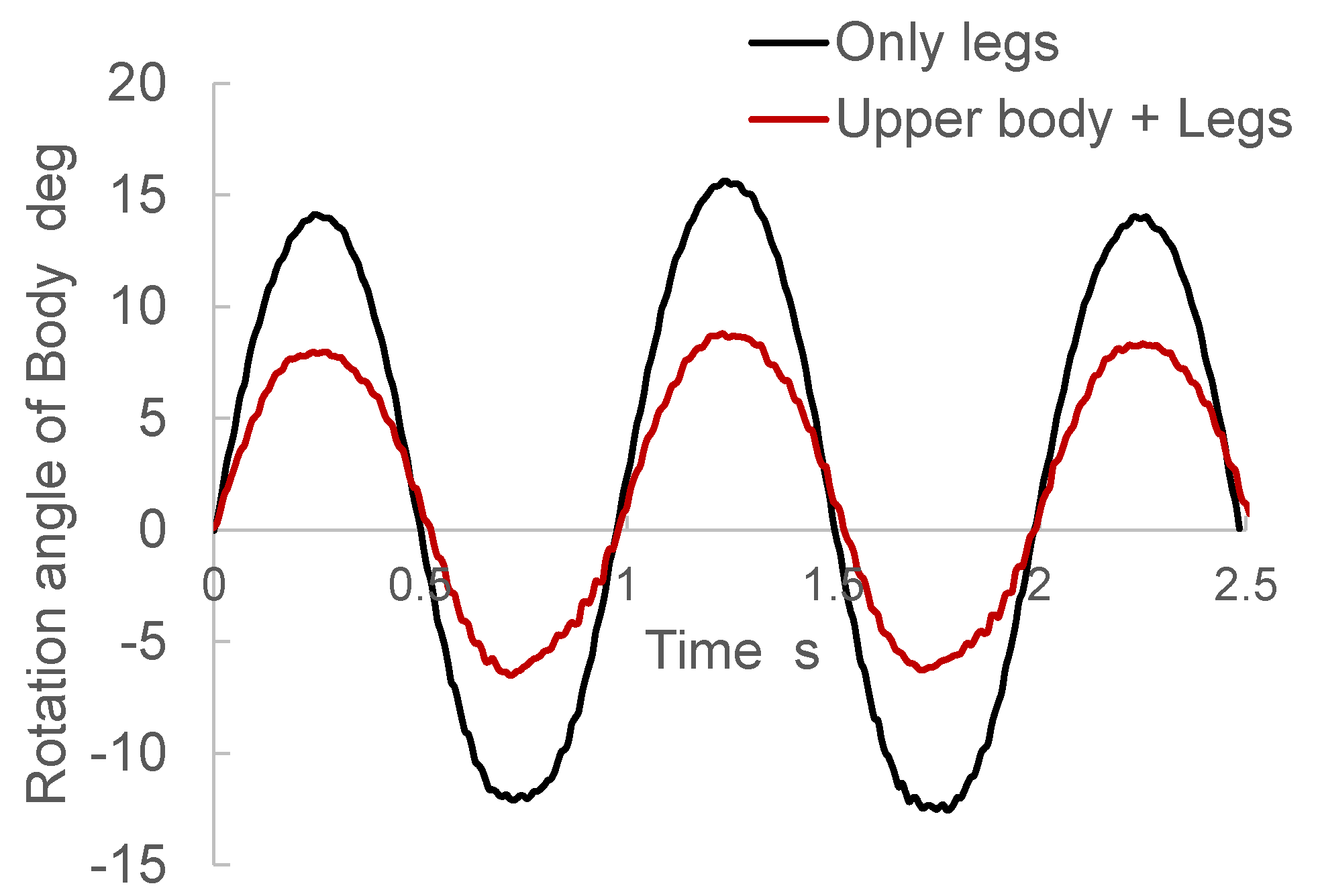
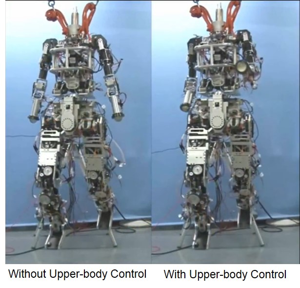
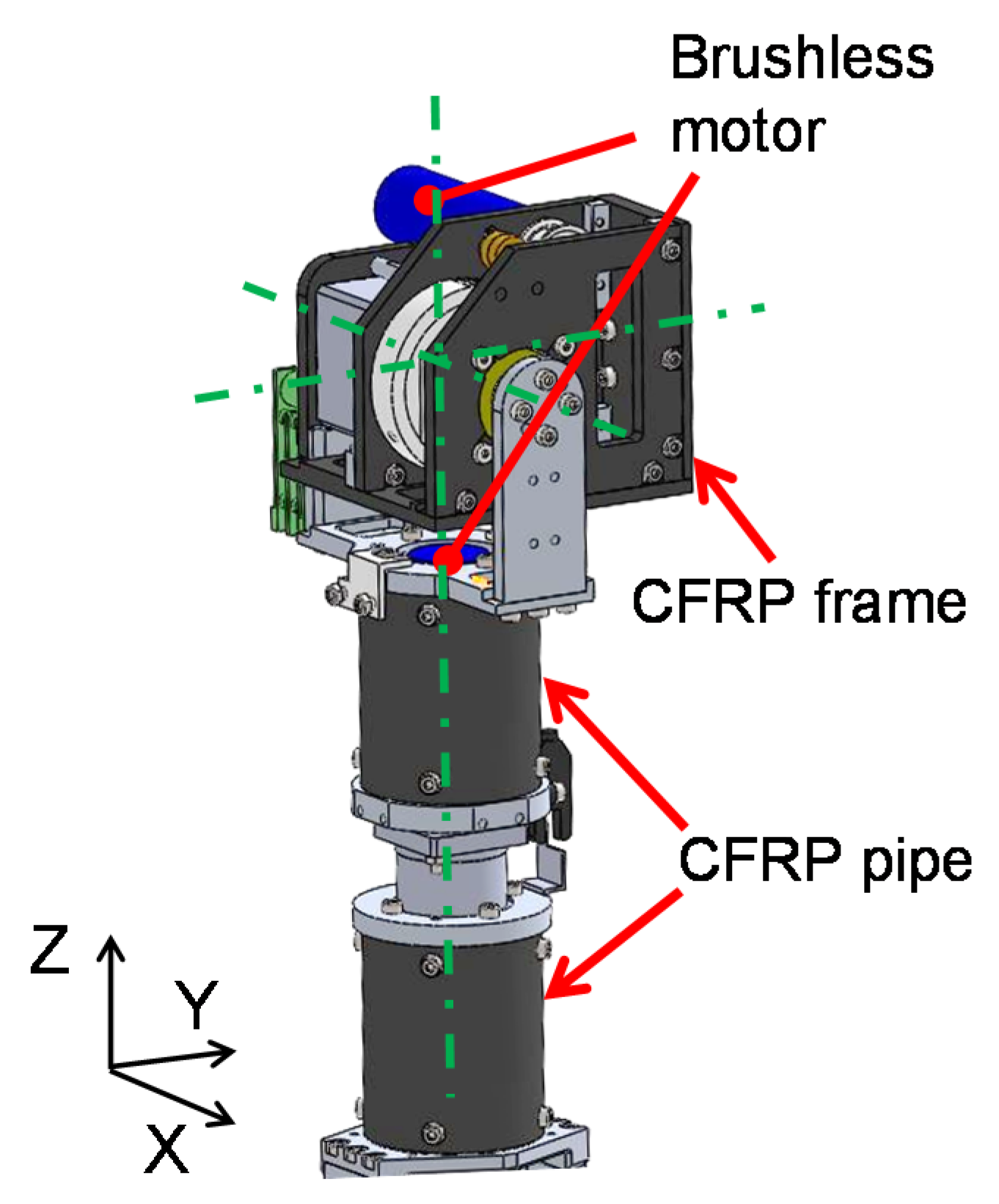
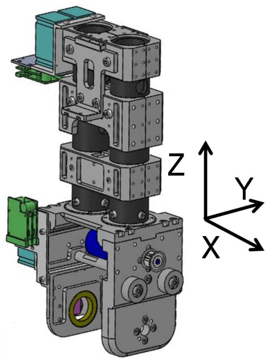
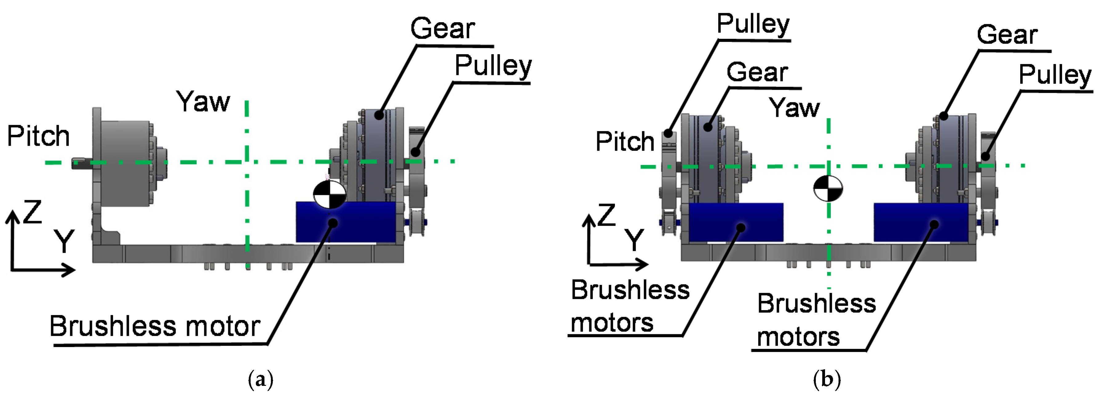
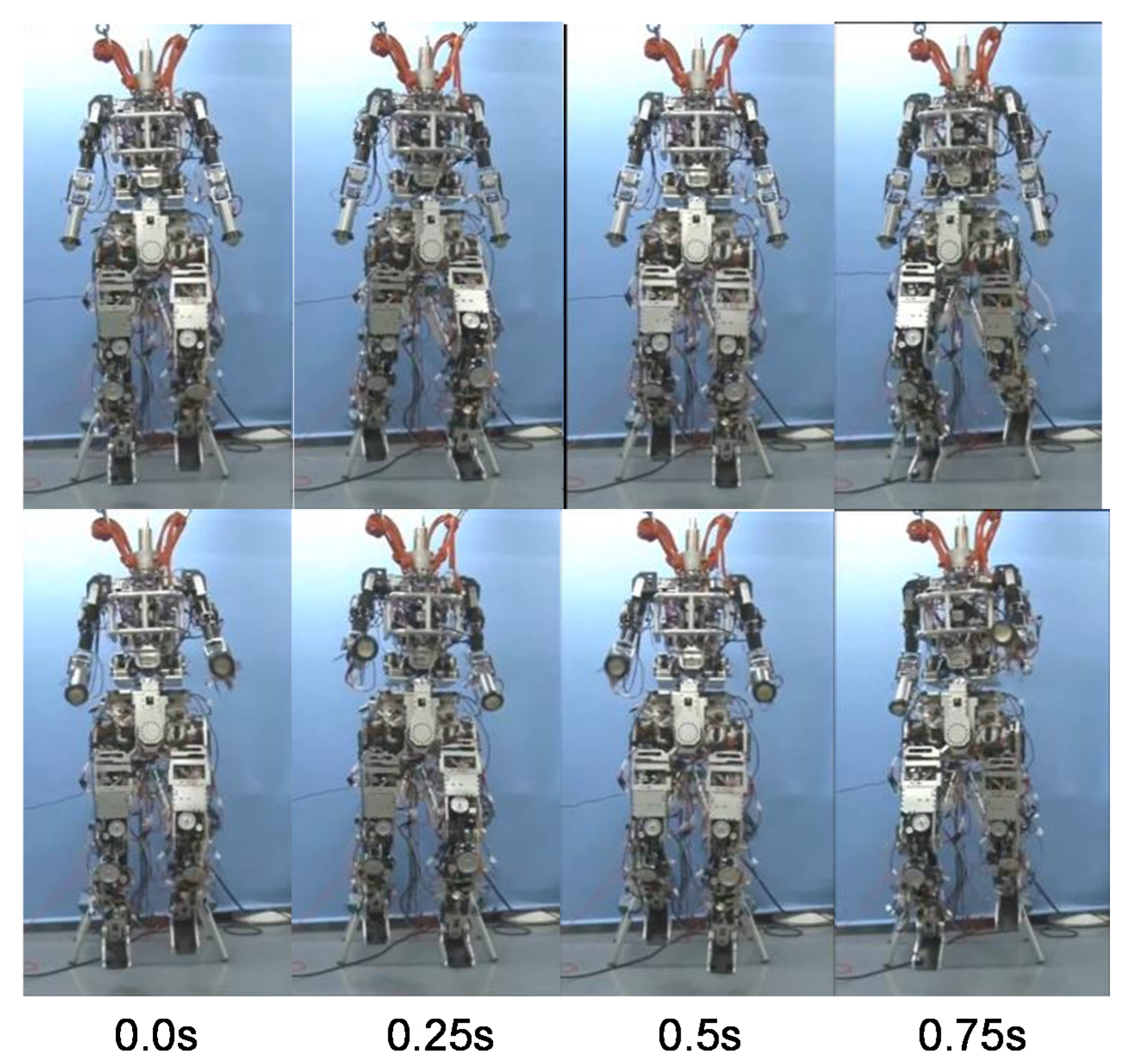
In this study, our focus is on the flight phase that occurs during the hopping or running motion of a robot, and we aimed to prevent rotation of the waist by aggressively generating angular momentum with the upper body equivalent to that generated by the legs during the flight phase. To this end, we propose an angular momentum compensation control method that uses the arms and torso inspired by the mechanisms of human running. Moreover, to realize the proposed method with a real humanoid, we developed an upper-body mechanism to mimic human link lengths and mass properties. We performed experiments with the robot that we developed to evaluate the proposed methods. We confirmed that the humanoid robot could compensate for the angular momentum in the yaw direction that is generated by lower-body movement in midair.
The remainder of this paper is organized as follows. In Section 2, we describe the proposed method for compensating for angular momentum in the yaw direction and the design of the upper-body mechanism that mimics the human mass properties. In Section 3, we present the experimental results. In Section 4, we present a discussion. Finally, in Section 5, we present our conclusions.

2. Angular Momentum Compensation

2.1. Requirements for Angular Momentum Compensation

We identified the characteristics of upper-body movement of human running on the basis of previous research in human and sport sciences, and we based our determination of the requirements for a control method and an upper-body mechanism on these characteristics. Table 1 summarizes the characteristics we identified. Humans utilize the torso and arms to compensate for angular momentum in the yaw direction generated by the movement of the lower body during the flight phase, during which the human is not in contact with the ground [26]. Here, the trunk refers to the parts higher than the lumbar vertebrae, and the trunk joints refer to the virtual joint between the trunk and the lumbar vertebrae, which consolidates the complex movements of the spine. Rapid leg swinging during the flight phase is responsible for the large angular momentum produced. To compensate for the large angular momentum, both the torso yaw joint and the shoulder pitch joints swing. The shoulder pitch joints swing widely and rapidly because of the inertial moment of the arms in the yaw direction. Most of that upper-body movement is in the yaw direction. In addition, the shoulder roll and yaw joints can change arm postures. A human extends his/her elbow joints according to his/her running speed [27]. The elbow joints can be used to adjust the inertial moment of the arms when large angular momentum is generated by quick lower-body movements. Therefore, we determined that the requisite joint motions of the upper-body mechanism are the three torso joint motions (pitch, roll, and yaw), the three shoulder joint motions (pitch, roll and yaw), and one elbow joint motion inspired by the human configuration.
Furthermore, we determined the requirements for the link lengths and mass properties of the upper-body mechanism based on human data [32,33] (see Table 2 and Table 3; note that in the tables, S.D. means the standard deviation). In Table 3, the moment of inertia is with respect to the center of mass position of each link. These parameters influence the angular momentum; however, ordinary humanoid robots have very light arms so as to decrease the required output power of the leg joint, and thereby cannot generate the large angular momentum to compensate that generated by the leg. Therefore, we assumed that employing human-like parameters would be useful to utilize the human-inspired angular momentum compensation method. The requirements of the total mass and total height are 60 kg and 1600 mm based on human data [33]. In addition, we determined the requirements of the joints. The requirements for the movable angles of the joints were determined based on those of a human [34]. The angular velocity was determined based on human running data obtained in our previous research [25]. The torque was calculated from the angular velocity and mass properties of each link. These requirements are listed in Table 4.

2.2. Upper-Body Control Method Based on Angular Momentum

We developed an angular momentum compensation method inspired by humans. In this method, the upper body, including the torso and arms, is controlled to compensate for the angular momentum generated by the movement of the legs during the flight phase. By using both torso and arms, the upper body can generate large angular momentum. In this paper, we present all vectors of position, angular velocity, linear momentum and angular momentum, and all rotation matrices in the Cartesian frame fixed on the ground. The inertia matrix is basically with respect to the center of mass position of the link presented in the Cartesian frame fixed on the ground. The process of the proposed method consists of four steps:
(1)
Selection of an angular momentum reference for a waist of the robot;
(2)
Calculation of the angular momentum generated by legs movement;
(3)
Calculation of the angular momentum that needs to be generated by movement of the torso and arms;
(4)
Generation of movement of each upper-body joint.
The angular momentum of the waist is first determined, based on if rotation in the yaw direction is needed. The angular momentum reference of the waist L w a i s t _ target should be 0 kgm2/s to perform straight running motion. Second, the angular momentum generated by leg movement is determined. The legs are controlled with controllers for running. In our previous studies, the controller decided a landing position and swung the legs to achieve the desired landing. When the leg movement is different, the angular momentum generated by the legs also changes. The legs’ angular momentum L l e g s is described by the following equation, considering the angular momentum of each link.
L l e g s = i = 1 L e g s _ l i n k L i
where, L i is the angular momentum of the ith link, which is generally calculated as shown in Equation (2) [19].
L i = c i × P i + R i T I ¯ i R i ω i
where, c i is the COM position of the ith link, P i is the linear momentum of the ith link, R i is the rotation matrix of the ith link, I ¯ i is the inertia matrix of the ith link with respect to the COM position of the link, and ω i is the angular velocity of the ith link. The inertia matrices are known as the designed parameters including the moment of inertia and products of inertia. The rotation matrix and the angular velocity are measured by the joint angle sensors implemented in the robot, and the linear momentum is calculated with mass and the COM position.
In the third step of the process, the angular momentum reference of the upper body L u p p e r b o d y _ target is calculated from the angular momentum of the whole body at take-off L a l l and the angular momentum L l e g s generated by the leg movement. By the same method for the calculation of the angular momentum L l e g s generated by the legs, the angular momentum of the whole body L a l l is calculated at take-off because it does not change during the flight phase.
L u p p e r b o d y _ target = L a l l L l e g s L waist _ target
The angular momentum reference of the upper body is divided into torso and arms components for compensation in the yaw direction. L t r u n k _ target and L a r m s _ target are the references of angular momentums generated by the movements of the torso and arms, respectively. The arm movement contribution is represented with gain K as shown in Equations (4) and (5).
L a r m s _ target = K L u p p e r b o d y _ target
L t r u n k _ target = ( E K ) L u p p e r b o d y _ target
The gain should be determined by the desired motion and the capacity of generating the angular momentum by each part of the robot. For stable running, both the trunk and arms should be used for generating large angular momentum. When the robot has very light arms and cannot generate angular momentum with arms, the gain should be lower.
Finally, the movements of the joints are determined. To generate L t r u n k _ target and L a r m s _ target , the robot controls its trunk and shoulder joints. The joint angular velocity reference of each joint is calculated using Equations (6)–(8).
ω r i g h t _ s h o u l d e r _ r e f = R r i g h t _ a r m T I ¯ r i g h t _ a r m 1 R r i g h t _ a r m ( L a r m s _ target 2 c r i g h t _ a r m × P r i g h t _ a r m )
ω l e f t _ s h o u l d e r _ r e f = ω r i g h t _ s h o u l d e r _ r e f
ω t r u n k _ r e f = R u p p e r b o d y T I ¯ u p p e r b o d y 1 R u p p e r b o d y ( L t r u n k _ target c u p p e r b o d y × P u p p e r b o d y )
where, c r i g h t _ a r m and c u p p e r b o d y are the COM positions of the right arm and the upper body, respectively. P r i g h t _ a r m and P u p p e r b o d y are the linear momentum of the right arm and the upper body, respectively. R r i g h t _ a r m and R u p p e r b o d y are the rotation matrices of the right arm and the upper body, respectively. I ¯ r i g h t _ a r m and I ¯ u p p e r b o d y are the inertial matrices of the right arm and the upper body with respect to the COM position of each part, respectively. The left and right shoulder joint motions are symmetrical with respect to the center.
Using this method, the joints of the torso and arms are controlled so that the angular momentum of the waist in the yaw direction is kept close to zero. The method will be used for various humanoid robots by changing the arm movement gain according to the capacity of generating the angular momentum by each part of the robot.

2.3. Design of the Upper-Body Mechanism

To fulfill the above requirements of an upper-body robot mechanism, we developed an upper-body mechanism that has human-like mass properties and can perform the motions observed during human running (see Figure 1). Some studies have been conducted using humanoid robots with upper-body mechanisms [7,10,11,35], but it is difficult to achieve human-like size, mass properties and motion. The reason for this is that human-like motion requires a high-power output, but high-power actuators are too heavy to mimic a human mass properties. For example, the mass of the upper arm of a human may be 1600 g. Three actuators are required in the upper arm for the shoulder and elbow joints. However, the mass of each actuator, including the gear, is approximately 400 g. We considered the use of brushless direct-current (DC) motors as actuators, because they are small and light and can output high power. Based on the upper body motion during human running shown in Table 4, the maximum joint power of the shoulder pitch and trunk joints is around 150 W, and that of other joints is even smaller. Implementation of such actuators requires that the mass of the other parts, such as the frames connecting each joint and the electric parts, be less than 400 g. We must save the weight of frames; however, the frames must bear the load derived from large angular momentum for preventing yaw rotation.
Therefore, we considered the material properties required for the structural members of the humanoid robot to best mimic the size and mass properties of a human. Aluminum is typically used for the structural members of a robot. The structure of the upper body of most humanoid robots are exoskeleton structures, wherein the frame shapes the body, and every component, such as motors and electrical parts, is stored in the frame. It is difficult to save the weight of the upper body because the amount of aluminum parts for shaping the body are increased. For weight saving in the links, we used carbon-fiber-reinforced plastic (CFRP), which is extremely strong yet also light. The density of CFRP (1.5 g/cm3) is much lower than that of aluminum (2.7 g/cm3). CFRP pipes were used in the center of each link, similar to the inner skeleton structure based on the human structure, with actuators, motor controllers and cables placed around the pipes (see Figure 2 and Figure 3). In the torso link, a large twisting moment is loaded for generating angular momentum in yaw direction. To stand the twisting moment, two pipes were implemented instead of one big pipe (Figure 3). Consequently, the size of each link was close to that of a human’s, and the mass of each link was approximately 11% less than if it were made of aluminum.
Achieving a human-like COM position and inertial moment requires axial symmetry of the structure of the torso. Some humanoids have a torso mechanism actuated by a motor and a gear implemented on only one side (see Figure 4a). In this type of mechanism, the COM position of the torso is inclined from the center in the frontal plane and is thus different from that of a human. It therefore produces an angular momentum that is different from that of a human. A humanoid robot developed using this type of mechanism cannot mimic human-like motion by generating the same angular momentum. A counterweight can be used to shift the COM position, but the total mass of the mechanism may still be too large compared with that of a human. To solve this problem, we implemented a symmetrical joint mechanism with two of the same actuators and gears (see Figure 4b). The COM position was thus shifted to the center of the torso, as in a human. With two actuators in parallel, each actuator and gear required less power when only one actuator was used, which made it possible to decrease the size and weight of the actuator. As a result, the mass of the mechanism was decreased by approximately 550 g compared to that associated with using a counterweight. The weight of each part of the upper-body mechanism could therefore be decreased. Thus, the weight could be freely distributed, and the COM position could be regulated more easily.
We combined the upper body developed as described above with the lower body to produce a whole-body humanoid (see Figure 5). The humanoid has 22 degrees-of-freedom (DOF) in total. The brushless DC motors which can output 200 W are implemented in the joints which needs large output such as the shoulder pitch, trunk, hip pitch, and knee joints. On the other hand, the smaller motors which can output 100 W are implemented in other joints. The specifications of the upper body for the link length and mass properties are listed in Table 5 and Table 6. The parameter values of the humanoid mimic those of a human in almost every respect. The mass of the humanoid is 60 kg, and the height is 1500 mm. In the case of a human, the COM position of the whole body is located near the pelvis, the height of which is approximately 56% of the standing body height [36]. The robot mimics the whole-body COM position by mimicking the link length, mass, and COM position of each link.

3. Experiments and Results

We performed two experiments to verify the capacity of generating angular momentum of the upper body and the effectiveness of the developed control method.

3.1. Verification of Active Generation of Angular Momentum as Large as that of a Human

We conducted an experiment using the humanoid upper body developed in this study to evaluate its capability to generate large angular momentum with human-like motion. We implemented the upper body on a six-axis force sensor for measuring the moment which the upper body applies to the lower part such as the waist of the robot. We calculated the angular momentum generated by the upper body of the robot integrating the moment data measured by the six-axis force sensor. The motion of the upper body was the same as that of human running motion obtained in our previous research [25]. The motion of each joint of human can be expressed as an approximate sine wave as Equation (9).
θ J O I N T = θ J O I N T _ I N I T I A L A J O I N T sin ( ω t )
where, θ J O I N T _ I N I T I A L is the initial joint angle, A J O I N T is the amplitude of the joint motion, ω is the natural frequency of the joint motion, and t is the elapsed time from the start of the experiment. Therefore, we determined the motion of the upper body of the robot as Equation (9). The experimental parameters and their value of each joint are listed in Table 7.
Moreover, we calculated the angular momentum generated by the human upper body and the simulation model with a 300 g lighter forearm at the same motion for evaluating the influence of the difference of the weight of the link on the generated angular momentum. After that, we compared the angular momentum generated by the upper body of the developed robot with that of human. The angular momentum of a human’s upper body was calculated with the human motion data and body parameters in Table 2 and Table 3.
Table 8 summarizes the results for angular momentum generated in the experiment, in simulation, and in human running. The results confirm that the upper-body mechanism developed in this study can generate angular momentum as large as in human motion. In addition, we calculated the angular momentum in the yaw direction with the upper-body model, which has a forearm 300 g lighter than a robot forearm. The maximum angular momentum generated with the upper-body model was 1.7 kgm2/s. On the other hand, a maximum angular momentum of 1.5 kgm2/s was generated with the lighter forearm model. The total weight of the lighter forearm model decreased by only 2.3%; however, the angular momentum in the yaw direction decreased by 12%. We confirmed the developed upper body can be used for active angular momentum control as human.

3.2. Angular Momentum Compensation in the Yaw Direction

We conducted an experiment to evaluate how effectively the humanoid could compensate for the angular momentum generated by the leg motion during the flight phase. In this experiment, the humanoid was suspended in midair to perform running motion during the flight phase without any constraint in the yaw direction. The lower-body joints were controlled according to the joint angle references based on the human motion data [25]. We verified the humanoid turning angles in the yaw direction depends on whether control is provided, which depended on the angular momentum in the yaw direction. We measured the turning angle of the waist in the yaw direction using a motion capture system that included infrared cameras used to determine three-dimensional marker positions at 120 Hz. Spherical retro-reflective markers were attached to the surface of the waist parts of the humanoid near the COM of the whole body. The motion capture system calculated the segment attitude using the position data for some of the markers. When angular momentum compensation was not employed, each joint of the upper body maintained a neutral position. When angular momentum compensation was employed, the angular momentum generated by the leg motion was calculated, and the upper body moved to compensate for the angular momentum actively. The ratios of the arms contribution and trunk contribution were determined to be 0.8 and 0.2, respectively, based on the human running data [26] in which the angular momentum generated by the arms was 1.2 kgm2/s and that generated by the trunk was 0.3 kgm2/s. The lower-body motion of each joint was determined to follow an approximate sine wave as Equation (10), based on the human running data [15].
θ H I P = θ H I P _ I N I T I A L A H I P sin ( ω t )
where, θ H I P _ I N I T I A L is the initial joint angle, A H I P is the amplitude of the joint motion, ω is the natural frequency of the joint motion, and t is the elapsed time from the start of the experiment. The experimental parameters and their values of joint movements are listed in Table 9.
Figure 6 illustrates the rotation angle of the humanoid waist in the yaw direction. Figure 7 presents photographs of the experiment. When the angular momentum compensation control was not employed, the humanoid rotated approximately 15 deg in the yaw direction. On the other hand, when the control was used, the rotation decreased to approximately 8 deg. The results confirm the effectiveness of the proposed angular momentum compensation control for stabilization in the yaw direction. It was assumed that the friction force in the yaw direction of the hanger influenced the angular momentum because it was small but not zero.

4. Discussion

In experiment 2, we could not perform a running experiment with the humanoid developed in this study because more work is required to develop methods for stabilization in the pitch and roll directions. During running, the vertical component of the ground reaction force can be up to 1800 N, which is much larger than the horizontal component of approximately 180 N [37]. Therefore, the ground reaction force influences stabilization in the pitch and roll directions but not in the yaw direction. When the ground reaction force does not act in alignment with the COM of the humanoid, angular momentum is generated and the robot falls. To prevent this situation, some researchers have focused on stabilization in the pitch and roll directions by controlling the ground reaction force [38,39]. In contrast, in this study, we focused on yaw stabilization using the upper body, because the ground reaction force does not have a large influence on stabilization in the yaw direction.
In this study, we designed an upper-body mechanism that has human-like link length and mass properties to achieve angular momentum compensation in the yaw direction during running. In experiment 1, we confirmed that the upper body could generate almost the same angular momentum as a human’s upper body during running. In addition, we calculated the angular momentum in the yaw direction with the 300 g lighter forearm. These results indicate that mass parameters have a large influence on the angular momentum generated during running. To achieve angular momentum compensation during running, it is important to incorporate the capacity of generating angular momentum in designing a humanoid robot. The upper body developed in this study was found to be able to perform fast movement as well as a human. This upper body will be useful in future research on effective sports movements such as ball throwing.
We propose in this paper an angular momentum compensation method using a humanoid upper body. This method can be used with other humanoid robots that do not have human-like mass properties. The reason for this is that the robot can calculate the angular momentum required using its mass property data and the control method developed. In addition, the control method can be applied to active turning by changing the angular momentum reference of the waist. In experiment 2, which involved running on a straight course, the angular momentum reference of the waist was set to zero.
In addition, we assume that the proposed method for stabilization in the yaw direction can be applied to stabilization in the pitch and roll directions with a change in the ground reaction force. In general, the upper body has a large mass and moment of inertia, and it can thus generate large angular momentum in the pitch, roll and yaw directions. The angular momentum generated by the ground reaction force can be compensated for by the upper-body motion. When the humanoid cannot effectively use its upper body, the humanoid should generate motion within a range that maintains the stabilization with only its legs and torso. By integrating these methods, the humanoid can perform faster and wider-ranging motions. In future work, we intend to apply the proposed method for stabilization to the pitch and roll directions. In addition, we will utilize the robot in the place of human subjects to confirm various running characteristics.
In summary, we found that the angular momentum compensation in the yaw direction using the upper body during the flight phase can improve the capability of humanoid hopping and running performance. Moreover, the upper body design should focus on the capability of generating angular momentum for rapid movement such as hopping and running. For stable running without constraints, the proposed method should be integrated with other control methods; however, humanoid robots will perform stable and faster motions by using the proposed methods, and the developed upper body will be useful in research about finding effective sport movements such as ball throwing.

5. Conclusions

In this paper, we propose an angular momentum compensation method to achieve angular momentum compensation in the yaw direction during the flight phase of running. The method is based on the human-running mechanism. To compensate for the angular momentum generated by lower-body movement during the flight phase, the angular momentum compensation method calculates the angular momentum and generates upper-body motion that activates the torso and arms, as in humans. The humanoid robot can thereby change its upper-body motion according to changes that occur in the lower-body motion, such as shifts in running speed. We also developed an upper-body mechanism that has the link and mass parameters similar to that of a human, and that can generate large angular momentum. We evaluated the developed upper body and noted that it could generate large angular momentum similar to that of humans. Furthermore, the minor differences in the link and mass parameters can significantly influence the capacity of generating angular momentum. Moreover, we confirmed that the humanoid robot could compensate for the angular momentum generated by the lower-body movement when the robot was suspended in midair.
The developed control method can contribute to improving the stability of humanoids that can perform dynamic movements including the flight phase, such as jumping, hopping and running. Because most other control methods for stabilization of the dynamic motion of humanoids focus on the stance phase, the developed method will be integrated without interference. However, using the developed control method requires the generation of large angular momentum by the upper body. To do that, the upper body design, which was not focused on in relevant studies, will also be changed to consider the mass, mass position, inertia matrix and link length for generating large angular momentum. Thanks to improved stability, humanoids will be able to advance into human living spaces and work stably.

Acknowledgments

This study was conducted with the support of the Research Institute for Science and Engineering, Waseda University; the Institute of Advanced Active Aging Research, Waseda University; the Future Robotics Organization, Waseda University, and as part of the humanoid project at the Humanoid Robotics Institute, Waseda University. It was also financially supported in part by JSPS KAKENHI Grant Nos. 25220005, 25709019, 17H00767; a Waseda University Grant for Special Research Projects (Project number 2017K-215); SolidWorks Japan K.K.; the DYDEN Corporation; and Cybernet Systems Co., Ltd. We thank all of these for the financial and technical support provided. We would like to thank Editage (www.editage.jp) for the English language editing.

Author Contributions

Takuya Otani, Kenji Hashimoto, Hiroki Ueta, Akira Natsuhara, Hum-Ok Lim, and Atsuo Takanishi developed the upper-body control; Takuya Otani, Kenji Hashimoto, and Shunsuke Miyamae performed the experiments; Masanori Sakaguchi and Yasuo Kawakami analyzed the human motion data; Hum-Ok Lim and Atsuo Takanishi helped to draft the manuscript, Takuya Otani wrote the paper, and all of the authors read and approved the final manuscript.

Conflicts of Interest

The authors declare no conflict of interest.

References

  1. Raibert, M.H. Legged Robots that Balance; MIT Press: Cambridge, MA, USA, 1986. [Google Scholar]
  2. Grimes, J.A.; Hurst, J.W. The Design of ATRIAS 1.0 a Unique Monopod, Hopping Robot. In Proceedings of the International Conference on Climbing and Walking Robots (CLAWAR), Baltimore, MD, USA, 23–26 July 2012; pp. 548–554. [Google Scholar]
  3. Martin, W.C.; Wu, A.; Geyer, H. Experimental Evaluation of Deadbeat Running on the ATRIAS Biped. IEEE Robot. Autom. Lett. 2017, 2, 1085–1092. [Google Scholar] [CrossRef]
  4. Hyon, S.; Emura, T.; Mita, T. Dynamics-based control of one-legged hopping robot. J. Syst. Control Eng. Proc. Inst. Mech. Eng. Part I 2003, 217, 83–98. [Google Scholar] [CrossRef]
  5. Nagasaka, K.; Kuroki, Y.; Suzuki, S.; Itoh, Y.; Yamaguchi, J. Integrated motion control for walking, jumping and running on a small bipedal entertainment robot. In Proceedings of the 2004 IEEE International Conference on Robotics and Automation, New Orleans, LA, USA, 26 April–1 May 2004; pp. 3189–3194. [Google Scholar]
  6. Kajita, S.; Nagasaki, T.; Kaneko, K.; Yokoi, K.; Tanie, K. A Running Controller of Humanoid Biped HRP-2LR. In Proceedings of the 2005 IEEE International Conference on Robotics and Automation, Barcelona, Spain, 18–22 April 2005; pp. 618–624. [Google Scholar]
  7. Cho, B.K.; Park, S.S.; Oh, J.H. Controllers for running in the humanoid robot, HUBO. In Proceedings of the IEEE-RAS International Conference on Humanoid Robots 2009, Paris, France, 7–10 December 2009; pp. 385–390. [Google Scholar]
  8. Wensing, M.P.; Orin, E.D. High-speed humanoid running through control with a 3D-SLIP model. In Proceedings of the 2013 IEEE/RSJ International Conference on Intelligent Robots and Systems, Tokyo, Japan, 3–7 November 2013; pp. 5134–5140. [Google Scholar]
  9. Tamada, T.; Ikarashi, W.; Yoneyama, D.; Tanaka, K.; Yamakawa, Y.; Senoo, T.; Ishikawa, M. High Speed Bipedal Robot Running Using High Speed Visual Feedback. In Proceedings of the 14th IEEE-RAS International Conference on Humanoid Robots, Madrid, Spain, 18–20 November 2014; pp. 140–145. [Google Scholar]
  10. Takenaka, T.; Matsumoto, T.; Yoshiike, T. Real-time Dynamics Compensation with Considering Ground Reaction Force and Moment Limit for Biped Robot. J. Robot. Soc. Jpn. 2014, 32, 295–306. [Google Scholar] [CrossRef]
  11. Tajima, R.; Honda, D.; Suga, K. Fast Running Experiments Involving a Humanoid Robot. In Proceedings of the IEEE International Conference on Robotics and Automation, Kobe, Japan, 12–17 May 2009; pp. 1571–1576. [Google Scholar]
  12. Niiyama, R.; Nishikawa, S.; Kuniyoshi, Y. Biomechanical Approach to Open-loop Bipedal Running with a Musculoskeletal Athlete Robot. Adv. Robot. 2012, 26, 383–398. [Google Scholar] [CrossRef]
  13. Grizzle, J.W.; Hurst, J.; Morris, B.; Park, H.W.; Sreenath, K. MABEL, a new robotic bipedal walker and runner. In Proceedings of the American Control Conference, St. Louis, MO, USA, 10–12 June 2009; pp. 2030–2036. [Google Scholar]
  14. Endo, T.; Miyashita, K.; Ogata, M. Kinetics factors of the lower limb joints decelerating running velocity in the last phase of 100 m race. Res. Phys. Educ. 2008, 53, 477–490. [Google Scholar] [CrossRef]
  15. Cavagna, G.A.; Franzetti, P.; Heglund, N.C.; Willems, P. The determinants of the step frequency in running, trotting and hoppin in man and other vertebrates. J. Physiol. 1988, 29, 81–92. [Google Scholar] [CrossRef]
  16. Blickhan, R. The Spring-mass Model for Running and Hopping. J. Biomech. 1989, 22, 1217–1227. [Google Scholar] [CrossRef]
  17. McMahon, T.; Cheng, G. The Mechanics of Running: How does Stiffness Couple with Speed? J. Biomech. 1990, 23, 65–78. [Google Scholar] [CrossRef]
  18. Ounpuu, S. The biomechanics of walking and running. Clin. Sports Med. 1994, 13, 843–863. [Google Scholar] [PubMed]
  19. Kajita, S.; Kanehiro, F.; Kaneko, K.; Fujiwara, K.; Harada, K.; Yokoi, K.; Hirukawa, H. Resolved Momentum Control: Humanoid Motion Planning based on the Linear and Angular Momentum. In Proceedings of the 2003 IEEE/RSJ International Conference on Intelligent Robots and Systems, Las Vegas, NV, USA, 27–31 October 2003; pp. 1644–1650. [Google Scholar]
  20. Orin, D.E.; Goswami, A.; Lee, S.H. Centroidal dynamics of a humanoid robot. Auton. Robots 2013, 35, 161–176. [Google Scholar] [CrossRef]
  21. Gunther, M.; Blickhan, R. Joint stiffness of the ankle and the knee in running. J. Biomech. 2002, 35, 1459–1474. [Google Scholar] [CrossRef]
  22. Kuitunen, S.; Komi, P.V.; Kyrolainen, H. Knee and ankle joint stiffness in sprint running. Med. Sci. Sports Exerc. 2002, 34, 166–173. [Google Scholar] [CrossRef] [PubMed]
  23. Ferber, R.; Davis, I.M.; Williams, D.S., III. Gender Differences in Lower Extremity Mechanics during Running. Clin. Biomech. 2003, 18, 350–357. [Google Scholar] [CrossRef]
  24. Chapman, A.E.; Caldwell, G.E. Factors determining changes in lower limb energy during swing in treadmill running. J. Biomech. 1983, 16, 69–77. [Google Scholar] [CrossRef]
  25. Otani, T.; Hashimoto, K.; Yahara, M.; Miyamae, S.; Isomichi, T.; Hanawa, S.; Sakaguchi, M.; Kawakami, Y.; Lim, H.; Takanishi, A. Utilization of Human-Like Pelvic Rotation for Running Robot. Front. Robot. 2015. [Google Scholar] [CrossRef]
  26. Hinrichs, N.R. Upper Extremity Function in Running. II: Angular Momentum Considerations. Int. J. Sport Biomech. 1987, 3, 242–263. [Google Scholar] [CrossRef]
  27. Hinrichs, N.R. Whole Body Movement: Coordination of Arms and Legs in Walking and Running. In Multiple Muscle Systems; Springer: New York, NY, USA, 1990; pp. 694–705. [Google Scholar]
  28. Otani, T.; Hashimoto, K.; Isomichi, T.; Sakaguchi, M.; Kawakami, M.; Lim, H.O.; Takanishi, A. Joint Mechanism That Mimics Elastic Characteristics in Human Running. Machines 2016, 4, 5. [Google Scholar] [CrossRef]
  29. Otani, T.; Hashimoto, K.; Yahara, M.; Miyamae, S.; Isomichi, T.; Sakaguchi, M.; Kawakami, Y.; Lim, H.O.; Takanishi, A. Running with Lower-Body Robot That Mimics Joint Stiffness of Humans. In Proceedings of the of the IEEE International Conference on Intelligent Robots and Systems 2015, Hamburg, Germany, 28 September–2 October 2015; pp. 3969–3974. [Google Scholar]
  30. Sugihara, T.; Nakamura, Y.; Inoue, H. Realtime Humanoid Motion Generation through ZMP Manipulation based on Inverted Pendulum Control. In Proceedings of the IEEE International Conference on Robotics and Automation, Washington, DC, USA, 11–15 May 2002; pp. 1404–1409. [Google Scholar]
  31. Hyon, S.H.; Yokoyama, N.; Emura, T. Back handspring of a multi-link gymnastic robot—Reference model approach. Adv. Robot. 2006, 20, 93–113. [Google Scholar] [CrossRef]
  32. Ae, M.; Tang, H.; Yokoi, T. Estimation of inertia properties of the body segments in Japanese athletes. Soc. Biomech. 1992, 11, 23–33. [Google Scholar] [CrossRef]
  33. Kouchi, M.; Mochimaru, M. Human Dimension Database; AIST Digital Human Research Center: Tokyo, Japan, 2005. [Google Scholar]
  34. Nakamura, R.; Saito, H. Fundamental Kinesiology, 4th ed.; Kendall Hunt Publishing Company: Dubuque, IA, USA, 1992. [Google Scholar]
  35. Nagasaki, T.; Kajita, S.; Kaneko, K.; Yokoi, K.; Tanie, K. A Running Experiment of Humanoid Biped. In Proceedings of the IEEE/RSJ International Conference on Intelligent Robots and Systems, Sendai, Japan, 28 September–2 October 2004; pp. 136–141. [Google Scholar]
  36. Shima, K. Effect of Masticatory Movement on Head, Trunk and Body sways during Standing Position. Ph.D. Thesis, Hokkaido University, Sapporo, Japan, 2015. [Google Scholar]
  37. Farley, C.T.; Ferris, D.P. Biomechanics of walking and running: Center of mass movements to muscle action. Exerc. Sport Sci. Rev. 1998, 26, 253–285. [Google Scholar] [CrossRef] [PubMed]
  38. Sreenath, K.; Park, H.W.; Poulakakis, I.; Grizzle, J.W. Embedding active force control within the compliant hybrid zero dynamics to achieve stable, fast running on MABEL. Int. J. Robot. Res. 2013, 32, 324–345. [Google Scholar] [CrossRef]
  39. Kajita, S.; Kaneko, K.; Morisawa, M.; Nakaoka, S.; Hirukawa, H. ZMP-based Biped Running Enhanced by Toe Springs. In Proceedings of the IEEE International Conference on Robotics and Automation, Roma, Italy, 10–14 April 2007; pp. 3963–3969. [Google Scholar]
Figure 1. Computer-aided design (CAD) of the developed humanoid.
Applsci 08 00044 g001
Figure 2. CAD of the humanoid robot arm. The green line is the rotational axis. CFRP: carbon-fiber-reinforced plastic.
Applsci 08 00044 g002
Figure 3. CAD of the humanoid robot trunk. Two CFRP pipes are implemented in the center. Bottom parts are connected to trunk joints.
Applsci 08 00044 g003
Figure 4. CAD of the trunk joint mechanism of the humanoid robot. The green line is the rotational axis. (a) Ordinary mechanism; (b) Mechanism developed in this study.
Applsci 08 00044 g004
Figure 5. Whole-body running robot. The blue joint is the roll axis, the red joint is the pitch axis, and the yellow joint is the yaw axis. In the knee and ankle joints, a variable joint stiffness mechanism is implemented for storing jumping energy. (a) Humanoid robot; (b) DOF (degrees-of-freedom) configuration.
Applsci 08 00044 g005
Figure 6. Experimental results for angular momentum compensation.
Applsci 08 00044 g006
Figure 7. Experiment with a real robot. Upper row shows the experiment without angular momentum control. Lower row shows the experiment with angular momentum control. The humanoid was suspended with orange cables connected to a hanger, which could rotate passively in the yaw direction, and did not contact with the ground.
Applsci 08 00044 g007
Table 1. Characteristics of the upper body during human running.
JointsCharacteristics
Trunk RollBending for angular momentum compensation
Trunk PitchBending for angular momentum compensation
Trunk YawSwing for generating angular momentum
Shoulder RollFor changing the position of the center of mass
Shoulder PitchWide and rapid swing for generating large angular momentum
Shoulder YawFor changing the position of the center of mass
Elbow PitchChanging the position of the center of mass and moment of inertia of the arm
Table 2. Mass, COM (center-of-mass) position, and link length requirements for an upper-body mechanism.
LinksMass (S.D.) kgCOM Position (S.D.) mmLink Length (S.D.) mm
Trunk16120 (10) a270 (20)
Upper arm1.6 (0.10)150 (10) b270 (14)
Forearm0.90 (0.06)90 (5.0) c220 (11)
a from the waist; b from the shoulder; c from the elbow.
Table 3. Moment of inertia requirements for an upper-body mechanism.
LinksIxx (Roll) kgm2Iyy (Pitch) kgm2Izz (Yaw) kgm2
Trunk1.5 × 10−11.4 × 10−11.0 × 10−1
Upper arm6.5 × 10−37.0 × 10−31.7 × 10−3
Forearm4.1 × 10−34.2 × 10−37.0 × 10−4
Table 4. Requirements for upper-body joints.
JointsMovable Range DegAngular Velocity (S.D.) rpmTorque (S.D.) Nm
Shoulder Pitch−180–5050 (15)21 (8.8)
Shoulder Roll0–18025 (5.9)12 (6.8)
Shoulder Yaw−80–6029 (1.9)4.8 (2.2)
Elbow Pitch−145–569 (12)17 (1.9)
Trunk Pitch−45–3018 (9.5)77 (27)
Trunk Roll−50–5014 (4.7)64 (25)
Trunk Yaw−40–4036 (9.2)40 (15)
Table 5. Upper-body specifications of the humanoid.
LinksMass (S.D.) kgCOM Position (S.D.) mmLink Length (S.D.) mm
Trunk16130270
Upper arm1.6140260
Forearm0.9090210
Table 6. Moment of Inertia of the upper body of the humanoid.
LinksIxx (Roll) kgm2Iyy (Pitch) kgm2Izz (Yaw) kgm2
Trunk1.4 × 10−11.3 × 10−10.60 × 10−1
Upper arm7.3 × 10−37.4 × 10−31.1 × 10−3
Forearm4.5 × 10−34.4 × 10−34.4 × 10−4
Table 7. Experimental conditions.
ParametersValue
Trunk pitch amplitudedeg4.7
Trunk pitch initial angledeg12
Trunk roll amplitudedeg13.8
Trunk roll initial angledeg0
Trunk yaw amplitudedeg15.5
Trunk yaw initial angledeg0
Shoulder pitch amplitudedeg20.5
Shoulder pitch initial angledeg37.8
Movement periods0.6
Table 8. Max. angular momentum generated by upper-body of human and the humanoid.
ObjectsMax. Generated Angular Momentum kgm2/s
RollPitchYaw
Humanoid upper body5.52.31.7
Simulation with light forearm5.32.31.5
Human upper body5.52.51.5
Table 9. Experimental conditions.
ParametersValue
Hip pitch amplitude A H I P deg15
Hip pitch initial angle θ H I P _ I N I T I A L deg10
Knee pitch amplitudedeg20
Knee pitch initial angledeg150
Ankle pitch amplitudedeg0
Ankle pitch initial angledeg90
Movement periods1.0
Arm gain of angular momentum controlK0.8
Torso gain of angular momentum control0.2

