Locomotion Efficiency Optimization of Biologically Inspired Snake Robots


1
Centre for Autonomous Marine Operations and Systems, Department of Engineering Cybernetics at NTNU, NO-7491 Trondheim, Norway
2
Department of Engineering Cybernetics at NTNU, NO-7491 Trondheim, Norway
*
Author to whom correspondence should be addressed.
Appl. Sci. 2018, 8(1), 80; https://doi.org/10.3390/app8010080
Submission received: 6 November 2017
/
Revised: 23 November 2017
/
Accepted: 21 December 2017
/
Published: 9 January 2018
(This article belongs to the Special Issue Bio-Inspired Robotics)
Abstract
:Snake robots constitute bio-inspired solutions that have been studied due to their ability to move in challenging environments where other types of robots, such as wheeled or legged robots, usually fail. In this paper, we consider both land-based and swimming snake robots. One of the principal concerns of the bio-inspired snake robots is to increase the motion efficiency in terms of the forward speed by improving the locomotion methods. Furthermore, energy efficiency becomes a crucial challenge for this type of robots due to the importance of long-term autonomy of these systems. In this paper, we take into account both the minimization of the power consumption and the maximization of the achieved forward velocity in order to investigate the optimal gait parameters for bio-inspired snake robots using lateral undulation and eel-like motion patterns. We furthermore consider possible negative work effects in the calculation of average power consumption of underwater snake robots. To solve the multi-objective optimization problem, we propose transforming the two objective functions into a single one using a weighted-sum method. For different set of weight factors, Particle Swarm Optimization is applied and a set of optimal points is consequently obtained. Pareto fronts or trade-off curves are illustrated for both land-based and swimming snake robots with different numbers of links. Pareto fronts represent trade-offs between the objective functions. For example, how increasing the forward velocity results in increasing power consumption. Therefore, these curves are a very useful tool for the control and design of snake robots. The trade-off curve thus constitutes a very useful tool for both the control and design of bio-inspired snake robots. In particular, the operators or designers of bio-inspired snake robots can choose a Pareto optimal point based on the trade-off curve, given the preferred number of links on the robot. The optimal gait parameters for the robot control system design are then directly given both for land-based and underwater snake robots. Moreover, we are able to obtain some observations about the optimal values of the gait parameters, which provide very important insights for future control design of bio-inspired snake robots.
1. Introduction
Several robotic systems have been developed over the last few decades with the overall goal to be used for different applications and take the place of humans in dull, distant, or dangerous environments, including space applications, subsea applications and manufacturing processes. Recently, bio-inspired robots have received significant attention in research. The overall idea of bio-inspired robots is to make systems learn the concepts of the locomotion from nature and apply them to the design and the locomotion of the robotic systems. In many instances, to address scientific problems, engineers seek for solutions by getting inspired from the nature. In particular, they study the robust motion capabilities of biological creatures that have emerged through millions of years of evolution, and this process is termed biomimetics. Nowadays, there has been increasing interest on using robotic systems for exploration, monitoring, and surveillance tasks. Bio-inspired robotic systems that mimic the motion of biological snakes or fish can be considered good candidates for these kinds of applications. Inspired by the robustness and the stability of biological snake locomotion, snake robots carry the potential to meet the growing need for new technology that can be used in challenging environments [1]. Several models have been proposed for bio-inspired snake robots moving on land [1]. In [2], the locomotion capabilities of biological snakes has been studied, while the world’s first snake-like robot was developed in Japan in 1972 [3]. Bio-inspired snake robots have the potential to be used in several applications such as inspection and intervention operations in hazardous environments in industrial plants, manipulator tasks in tight spaces for instance pipe inspection. In addition, the robotic community signified the need for new technology that can be employed to locate survivors inside a collapsed building. Hence, a very relevant application of bio-inspired snake robots can involve search and rescue missions in earthquake areas in the future [1]. Furthermore, several results have been published regarding the design, modeling and control of bio-inspired underwater robots [4]. One of the main characteristics of snake robots is their adaptability to different motion demands. This attribute is extremely important for snake robots, since they have the ability to move over land as well underwater, while the physiology remains the same.
Nowadays, different types of underwater vehicles and underwater robotic systems have been used for several challenging subsea inspection and interventions tasks [5]. In addition to the existing underwater robotic solutions, recently, the potential of using bio-inspired underwater snake robots has been studied. Due to their long, flexible and slender body the snake robots can be considered as an interesting alternative solution to improve the efficiency and maneuverability of conventional underwater vehicles [6,7,8,9]. The swimming snake robot as a mobile manipulator arm can be used for several applications such as inspection and maintenance of subsea oil and gas installations accessing tight structures, in biological community and marine archeology. However, several control related challenges must be addressed before we have fully functional swimming snake robots suitable for challenging tasks in highly uncertain subsea environment. An essential problem to be solved is related to the locomotion efficiency of the bio-inspired swimming snake robots. Hence, in this paper, the energy efficiency is studied since it constitutes the main important factor in order to obtain long term autonomy of these type of robots.
In [10], gait parameters of a land-based snake robot are obtained to optimize head stability and the speed of the robot simultaneously. However, the energy efficiency is not considered in the optimization framework. In [11], the genetic algorithm (GA) is used to find forward head serpentine gait parameters for a land-based snake robot. However, only the speed of the robot is considered in the optimization in order to find the optimal gait parameters of the head link. Moreover, in [12] gradient-free method is implemented by using Powell’s method in order to optimize the forward velocity of the land-based and swimming snake robots. However, the frequency of the motion pattern has not been included in the optimized parameters. In [13], empirical rules have been derived for underwater snake robots based on extensive simulation studies describing the relationship between the different gait parameters, the power consumption and the achieved velocity for lateral undulation and eel-like motion patterns. Furthermore, in [14], the energy consumption of underwater snake robots (USRs) and remotely operated vehicles (ROVs) have been studied. The obtained comparison results in [14] between USRs and ROVs showed that the USRs are more energy efficient. Experimental results regarding the locomotion efficiency of USRs have been presented in [15], showing the relationship between the gait parameters, the achieved forward velocity and the energy consumption for the lateral undulation and eel-like motion patterns. An optimization framework is proposed in [16] for underwater snake robots. In particular, in [16] the energy efficiency of underwater snake robots was investigated solving a multi-objective optimization problem for a robot with 10 links. To the best of our knowledge, however, no results have been presented formulating an effective and general optimization framework for bio-inspired snake robots with an arbitrary number of links. In this paper, we consider both the minimization of the power consumption and maximization of the forward velocity, and we propose a framework for solving a multi-objective optimization problem in order to obtain optimal gait parameters. Based on the proposed method, in this paper, we investigate the motion efficiency of both land-based and underwater snake robots using undulatory motion patterns. Furthermore, we here take into account the negative work effect of underwater snake robots, which was not considered in [16]. The optimization framework proposed in this paper is thus an extension of the method presented in [16] and may be used for bio-inspired snake robots locomotion both on land and in water.
In this paper, we solve a motion optimization problem to obtain the optimal gait parameters based on a dynamic model of USR. The optimization problem is challenging as the USR model includes highly nonlinear hydrodynamic effects. Several models have been proposed for USRs in previous studies [7,8,17,18,19,20]. A closed form model for USRs was presented in [6,21,22], where both the resistive and reactive fluid forces were considered. In particular, the proposed model in [6,21,22], considers several hydrodynamic effects such as the linear and the nonlinear drag forces, the added mass effect, the fluid moments and current effects. This model is general in the sense that it can be used to simulate the behavior of snake robots moving on land or swimming in the water by considering either ground friction [1] or fluid friction model [6]. In this paper, the optimization results are obtained based on this model.
To optimize both the power consumption and the forward velocity, a weighted sum of both objective functions is proposed as a single goal. Optimization algorithms can be divided into two main classes: gradient-based and derivative free algorithms. Gradient-based algorithms are generally faster than the derivative free ones. However, the optimization solution in the gradient-based methods often depends on the initial points, since these algorithms are more prone to get trapped in local optima [23]. Therefore, derivative-free and more specifically stochastic derivative-free methods are reported to be used more often in problems with highly non-smooth objective functions containing multiple optima, because these types of algorithms can avoid local solutions by their stochastic nature. Consequently, as also mentioned in [8], we find that stochastic derivative-free methods constitute a proper optimization algorithm for the motion optimization problem. In [24], a genetic algorithm (GA) is applied to a three-link swimmer to solve the swimming gait optimization problem. Moreover, pattern optimization of anguilliform swimming is studied in [25]. In particular, a combination of an evolutionary optimization algorithm and a three-dimensional numerical solution are implemented. Two objective functions of efficiency and velocity are considered in [25], and the optimization problem is addressed by solving Navier–Stokes equations. Because of the computational cost of solving the Navier–Stokes equations, only one optimization run is considered for each fitness goal. In [8], optimization is used to generate efficient hyper-redundant mechanism swimming gaits. In particular, the gait parameters were optimized in order to minimize the total required energy over a given distance for a desired swimming velocity. Therefore, a penalty term was added to the objective function to set the velocity to the desired value. Since the penalty factor is chosen relatively large, the velocity tends to stay at the desired value, and thus it is difficult to observe the trade-off between the velocity and the required energy. However, we will show in this paper that a slight reduction of velocity may result in a significant saving in power consumption. In particular, we propose to optimize both the energy and the velocity, simultaneously. Therefore, there is no need to tune the penalty factor or define the desired velocity.
We apply the particle swarm optimization (PSO) algorithm to optimize the power consumption and the forward velocity. PSO iterates on the gait parameters in order to improve a candidate solution. Kennedy and Eberhart [26] developed the PSO algorithm inspired by the social behavior of animals. A random velocity is assigned to each particle according to simple mathematical formulae including the experience of the particle itself and its neighborhoods. The position of the particle is updated using the obtained new velocity. More specifically, the movement of the particle is influenced by the best experienced position of the particle itself and also the best known position of the swarm. The later helps the swarm to move toward the best solutions. In the PSO algorithm, there is few or no assumption about the optimization problem. Moreover, the gradient information is not required in the optimization procedure. Therefore, there is no limitation about differentiability of the optimization problem. In contrast to GA, PSO acquires memory and saves the experience of good solutions during generations. More importantly, the particles in PSO share the information among the neighborhood. Therefore, the mechanism of constructive cooperation results in a quicker convergence rate. In addition, quite recently, the Reinforcement Learning (RL) method has been applied to address optimization problems in robotics field [27]. To converge to the solution, many objective function evaluations are required in both the PSO and RL methods. However, PSO can use parallel computing to evaluate the objective functions of the particles of each generation. Therefore, it is possible to reduce the computational time significantly. [28] compares the PSO and RL methods applied to solve the obstacle avoidance problem for multi-robotic systems. The results in [28] shows that PSO gives a higher fitness than RL.
In this paper, a multi-objective optimization framework is proposed with the overall goal to maximize the achieved forward velocity and simultaneously minimize the average power consumption for bio-inspired snake robots. The optimization problem is solved based on the dynamic model of snake robots proposed in [6,21,22]. In particular, multi-objective optimization is used in order to obtain results for lateral undulation and eel-like motion patterns for swimming snake robots with different numbers of links. Furthermore, results are obtained also considering the negative work effect [8] of underwater snake robots. In addition, for land-based snake robots, optimization results are presented for the lateral undulation motion pattern, which is the most common motion pattern for this type of robot. In [29], a multi-objective optimization method for objectives with input-dependent noise is proposed and applied to optimize the speed and head stability of the sidewinding gait of a snake robot. The energy efficiency of land-based snake robot with 16 links is studied in [30] by comparing the energy efficiency of sidewinding locomotion with that of lateral undulation and sinus-lifting motion. The multi-objective optimization approach is presented in [10] for land-based snake robots to optimize the head stability and speed, simultaneously. The dynamic model of the robot was considered as a black-box model. The speed was simply defined by the center of mass displacement after a given time. In order to consider the head stability, the estimated area through which the desired focal point swept was minimized. In [10], surrogate models are obtained by running a few experiments, while the objective functions are also optimized, simultaneously. Therefore, adding more optimization variables to the problem may lead to an increase in the number of experiments. In this paper, however, we propose to use a dynamic model of snake robots instead of a black-box model. Consequently, we reduce the cost of experiments. Moreover, we also consider minimizing the power consumption in our proposed optimization framework. Furthermore, the proposed optimization method obtains the optimal parameters giving the most efficient motion pattern for both land-based and swimming snake robots. The obtained results thus provide interesting insights regarding the control and the design of bio-inspired snake robots.
The rest of this paper is structured as follows. The dynamic models of underwater and land-based snake robots are presented in Section 2. Section 3 presents the proposed multi-objective optimization framework and Section 4 the results obtained for both land-based and swimming snake robots. Finally, conclusions and suggestions for further research are given in Section 5.
2. Modeling of Snake Robots
In this section, we briefly present the equation of motion of an USR since it will be used in the following sections to study the energy efficiency of snake robots based on the proposed multi-objective optimization framework in this paper. For more details, see [6,21,22].
2.1. Dynamic Model of Underwater Snake Robot
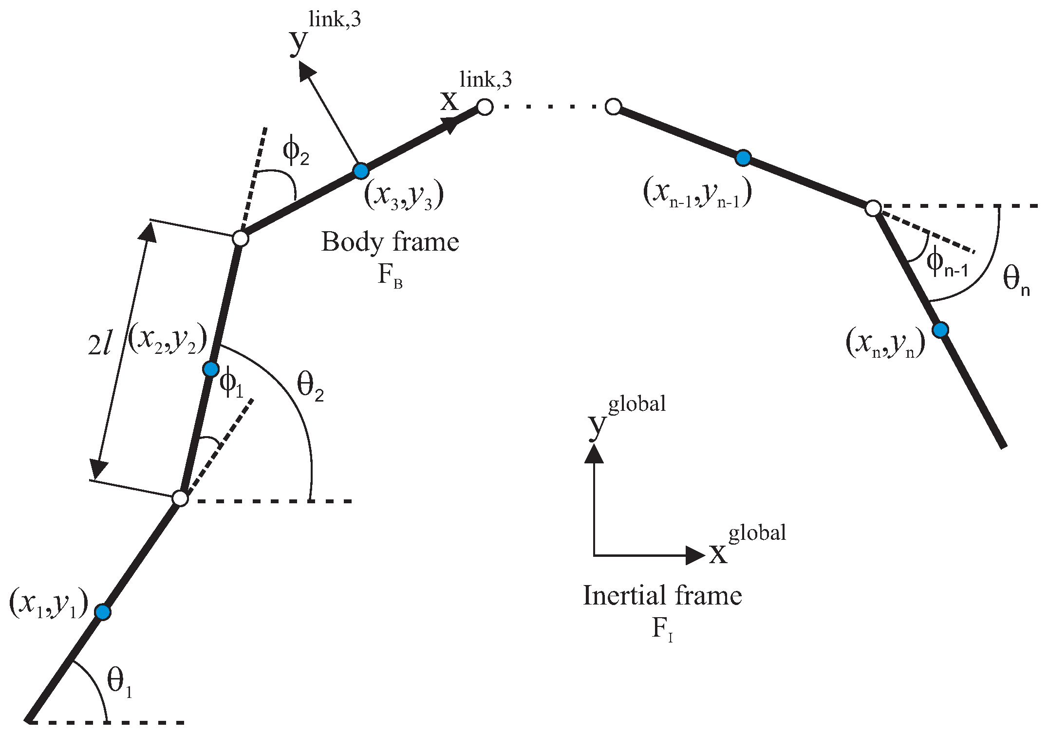
The robot is assumed to consist of n rigid links with each of them having length , mass m and moment of inertia . The links are interconnected by joints. The center of mass (CM) of the link is defined as the middle point, since it is assumed that the mass is uniformly distributed, with the total mass of the USR given by . The kinematics and dynamics of the robot will be described in terms of the mathematical symbols described in Table 1 and illustrated in Figure 1 and Figure 2. The following vectors and matrices are used in the subsequent sections:
where . Furthermore,
The kinematics of the robot is derived for a motion in horizontal plane. We assume that the robot is fully immersed in water and has in total n + 2 degrees of freedom (DOF). The parameters and represent the link angle and the joint angle of each link, respectively. The link angles and the joint angles are grouped in and . The position of the CM of the USR can be calculated as:
where are the global frame coordinates of the CM of link i, and .
Regarding the hydrodynamic modeling, in [6], it is shown that the global frame forces due to interaction of the links with the water can be assembled in vector form as follows:
where the added mass effects and in x and y direction, respectively, are given by
where , and represents the constant and irrotational ocean current effects. Furthermore, the linear and nonlinear drag forces on the robot are given by
where the relative velocities are given by
In addition, the fluid torques on all links are
where , and . The fluid parameters due to the drag and added mass effects are denoted by , , , and , , respectively. For more details see [6].
Combining the kinematics and the hydrodynamic model, in [6,21,22], it is shown that the equations of motion of an USR can be expressed as follows:
where and represent the drag forces in the x and y directions and the control input. For more details regarding the derivation of the vectors , , and and the matrices , , , , and , see [21,22].
2.2. Dynamic Model of Land-Based Snake Robot
Note that the dynamic model of an USR given by Equations (8) and (9) is general in the sense that it can be used to model the motion of amphibious snake robots moving both on land and in water. In particular, by setting the the fluid parameters to zero (i.e., setting , , , , and to zero) and replacing the drag forces Equations (4) and (5) with the following viscous friction model proposed in [1]:
the equation of motion of a land-based snake robot can be expressed as
The parameters and represent the viscous friction coefficients, while detailed derivation of the matrices and can be found in [1].
3. Optimization of Motion
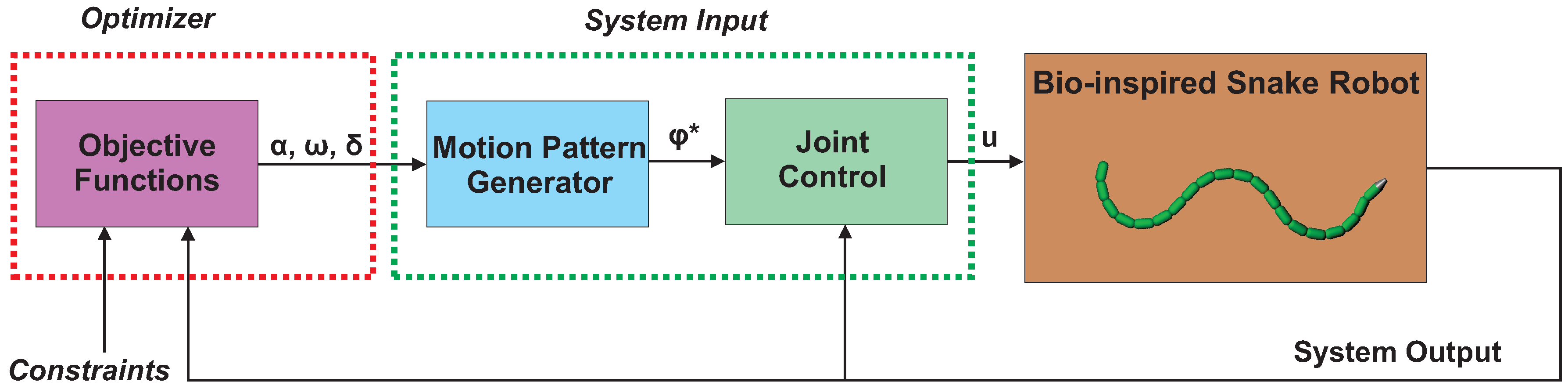
In this section, we propose an optimization framework to investigate the efficient motion of snake robots. As mentioned in the Introduction, the optimization approach presented in [16] for underwater snake robots is extended in this paper to consider both land-based and swimming snake robots, an arbitrary number of links, and also to take into account the negative work effect of swimming snake robots. Therefore, the proposed optimization framework of this paper is general since it can be widely applied to study locomotion efficiency of robotic systems using undulatory motion patterns to move forward. As shown in Figure 3, the optimization framework consists of three parts: (a) the plant, which in this paper is the model of a snake robot; (b) the system input, which combines the motion pattern generator with a joint actuation controller; and (c) an optimizer. Regarding the optimizer, the objective functions need to be evaluated for different values of the gait parameters for each simulation of the model in order to investigate the locomotion efficiency. The feasible region of the solution is also determined by defining the constraints, which are also inputs of the optimizer. More details regarding the system input and the optimizer parts used in this paper are given in the following sections.
3.1. System Input
As shown in Figure 3, the system input part consists of the motion pattern generator and the joint controller. In the following, both parts are discussed in detail.
3.1.1. Motion Pattern
Both land-based and swimming snake robots commonly use undulatory motion patterns in order to move forward. Previous studies on snake robots moving on land mostly adopt the lateral undulation motion pattern, which is considered as the fastest form of land-based snake robot locomotion [1]. Furthermore, studies on swimming snake robots often consider both lateral undulation and eel-like motion patterns as common motion modes to achieve propulsion. In [31], a general sinusoidal (undulatory) motion pattern was proposed, which makes it possible to describe different undulatory motion patterns including the lateral undulation and eel-like motion. To achieve an undulatory motion pattern, each joint of the snake robot is commanded to follow the reference signal
where the proper choice of the scaling faction makes it possible to describe different undulatory motion patterns. For instance, it is possible to achieve lateral undulation by simply choosing , while results in an eel-like motion pattern. The gait parameters , and give the amplitude, frequency and the phase shift of the sinusoidal motion pattern, respectively. Furthermore, the joint offset parameter is commonly used to control the heading of the robot [1].
3.1.2. Joint Actuation Controller
For low-level joint actuation, the following proportional–derivative (PD) controller is used:
where and denote the gains of the controller. For more details, see [1].
3.2. Formulation of the Optimization Problem
Solving an optimization problem entails finding a solution from all feasible solutions to maximize (or minimize) an objective function. In this paper, we define the motion optimization problem to optimize two objective functions, simultaneously: energy consumption, and the forward velocity. This type of optimization problem is called multi-objective optimization, since more than one objective function is involved [32]. In the following, these two objective functions (the energy consumption and the forward velocity) are formulated. To solve the bi-objective optimization problem, the well-known weighted-sum approach is implemented to combine these two objective functions.
First, we formulate the total energy consumption as a function of the actuation torque and the angular velocity of the joints:
where T represents the time of a complete motion cycle. The actuation torque and the angular velocity for joint i are calculated by using (14) and , respectively, [8,15].
Note that in this paper, we assume the joint to be ideal. Therefore, the total energy of the system is equal to the summation of kinetic energy and the energy which is dissipated due to either the ground friction for the land-based snake robot or the surrounding fluid for the underwater snake robot. The average power consumption is calculated by using the following expression:
Note that Equation (16) gives the average power consumption taking into account only the absolute value of the power consumed for the joint motion. However, in order to take into account also the effects of negative work [8], the net joint power can be considered instead. In this case, the average power consumption can be calculated using the following expression:
For underwater snake robots, both Equations (16) and (17) are examined. In the latter case which is presented in [8], it is shown that by considering the negative work effect the simulated robot is able to recover energy. However, for the land-based snake robot only the absolute values of the theoretical joint power is considered because the ground friction consumes energy when the robot moves on land, i.e., Equation (16) is used.
In addition, the following expression is used to calculate the forward velocity:
where and denote the initial and final positions of CM of the robot.
It is shown in [16] that the motion optimization problem can be formulated by the following objective functions and bound constraints:
where Equation (19b) represents the physical limitations of the joints because of the servo motors and special design of the snake robot [33], and Equation (19c) limits the possible range of the parameters of the sinusoidal motion pattern Equation (13).
As stated in [16], for the bi-objective optimization problem Equation (19), instead of a single global solution, there are a set of optimal solutions. Moreover, in this problem, the objective functions are in conflict such that minimizing the power consumption clearly results in decreasing the velocity and vice versa. In [16], we suggested using a Pareto optimality concept for the bi-objective optimization problem. In the optimization problem Equation (19), a solution is called Pareto optimal [32], if any improvement in power consumption cannot be achieved without a penalty of decreasing the forward velocity, or the forward velocity cannot have any higher value without requiring more power. The collection of Pareto optimal solutions is called the Pareto frontier or efficient frontier. Since the considered problem in this paper has two objective functions, it is possible to show the frontier in Cartesian coordinates. As stated before, one of the well-known ways to formulate the multi-objective optimization problem into a standard single objective function problem, is the weighted-sum approach:
where and represent scaled values of the power consumption and forward velocity, respectively, and and are the weighting coefficients. The solution is always the Pareto frontier, if the weighting factors are positive.
By sweeping the values of in the range of 0 and 1 (and correspondingly varying ) and solving the problem for each set of weights, Pareto optimal solutions and consequently Pareto frontier plots can be obtained. The single-objective function optimization problem is formulated by replacing the objective function to in Equation (20). In order to solve the motion optimization problem, the PSO algorithm was proposed in [16]. The PSO algorithm was first introduced by Kennedy and Eberhart in 1995 [26]. The PSO algorithm is a population-based stochastic algorithm and searches the search space using a set of potential solutions at each iteration (or generation). Each potential solution is named a particle, and the set of particles is called a population. The location of each particle in the new generation is updated by some equations. These equations are inspired by the social behavior of animals such as bird flocks or fish schools. For details regarding the implementation of the PSO algorithm, see [16].
Remark 1.
As stated before, in the optimization algorithm the plant is only required to evaluate the measure of efficiency (the objective function). This means that the multi-objective optimization approach proposed in this paper is general and thus can used to study locomotion efficiency of robotic systems using undulatory (sinusoidal) motion patterns such as Equation (13) to move forward.
Remark 2.
Note that including other design alternatives such as the number of links obviously leads to increasing the size of the optimization problem. Therefore, it might require more function evaluations to converge to the solution. Moreover, the designers might not be able to give us an initial guess for some of the parameters, which in turn leads to more computational time. In this paper we only include bound constraints. Nonlinear constraints, if any, can be handled by some constraint handling methods. In [34], two different constraint handling methods are coupled with the PSO algorithm. In addition, note that the optimality of the Pareto solutions can be checked by perturbing the optimization parameters and comparing the obtained objective function.
4. Optimization Study
The optimization results presented in this section consider snake robots moving on land and swimming underwater. The models of underwater and land-based snake robots were simulated using Matlab R2013b (MathWorks, Natick, MA, U.S.A, 2013). In particular, the ode23tb solver with both the relative and absolute errors being set to was used to simulate the dynamic equations presented in Section 2. The PSO is implemented using GenOpt, 3.1.1 (Lawrence Berkeley National Laboratory, Berkeley, CA, U.S.A, 2016), which is developed by Lawrence Berkeley National Laboratory and has parallel simulation run options for computation time reduction and allows using any simulation software to evaluate the cost function [35].
4.1. Parameters of the Robot
For the obtained results, the parameters of the robot are chosen to be identical to the underwater snake robot Mamba [33], i.e., each link having the length m and mass kg. Different configurations of the robot are investigated. In particular, we present results for , and number of links. The hydrodynamic parameters , , , , and were calculated for m and m, kg/m, , , and . For more details, see [6]. Furthermore, based on the discussion in [1], the viscous friction parameters are set to and . The gains of the PD joint controller given by Equation (14) are set to , and the sinusoidal motion pattern is achieved using Equation (13). Note that for the optimization results presented in this paper, we have not taken into account the effects from the ocean current, which remains topic of future work.
4.2. Optimization Parameters
The optimization problem formulated in Equation (19) includes 3 decision variables. Following the suggestion in [36], to use a population size equivalent to approximately 5 times the decision vector size, we set the number of particles equal to 16. Like other stochastic approximation algorithms, PSO has a few tunable parameters. There are extensive discussion about tuning of the PSO parameters in the literature. We here follow the recommendations in [36,37], which are based on the trials on a selection of different benchmark problems, to initialize the tuning parameters in the PSO algorithm. The values of the constraints in Equation (19b) are chosen in accordance with the limitations of the servo motors used in the snake robot presented in [33]. Therefore, we set the physical constraints of the joints to Nm, , /s. Regarding the range of the gait parameters in Equation (19c), Table 2 gives the values for both the underwater snake robot and the land-based snake robot. As can be seen in Table 2 for a snake robot with links, the values of the parameters and . These upper and lower limits are set to avoid collisions between the links during the motion of the robot with a large number of links. In addition, note that in this paper we have chosen to use since we are not aiming to control the heading of the robot.
In this paper, we sweep the range from 0 to 1 for by the step size of . Therefore, the first optimization problem is to only optimize the velocity (, in Equation (21)). The next optimization problems, the weight of the velocity is reduced gradually, while is increased. In the next step, we start to reduce the weight of the velocity , while increasing the power consumption weight . In order to reduce the computation cost of the PSO algorithm, the initial value of the optimization parameter for the first optimization problem is tuned based on expert knowledge. Moreover, the optimal solution of each problem is used as an initial value for the next optimization problem.
To obtain a Pareto optimal point, 320 simulation runs are required (16 particles and 20 generations). Using a distributed computing framework, the computation time to obtain a Pareto optimal point for the optimization problem considered in this paper is approximately 65 minutes.
4.3. Results for Underwater Snake Robots
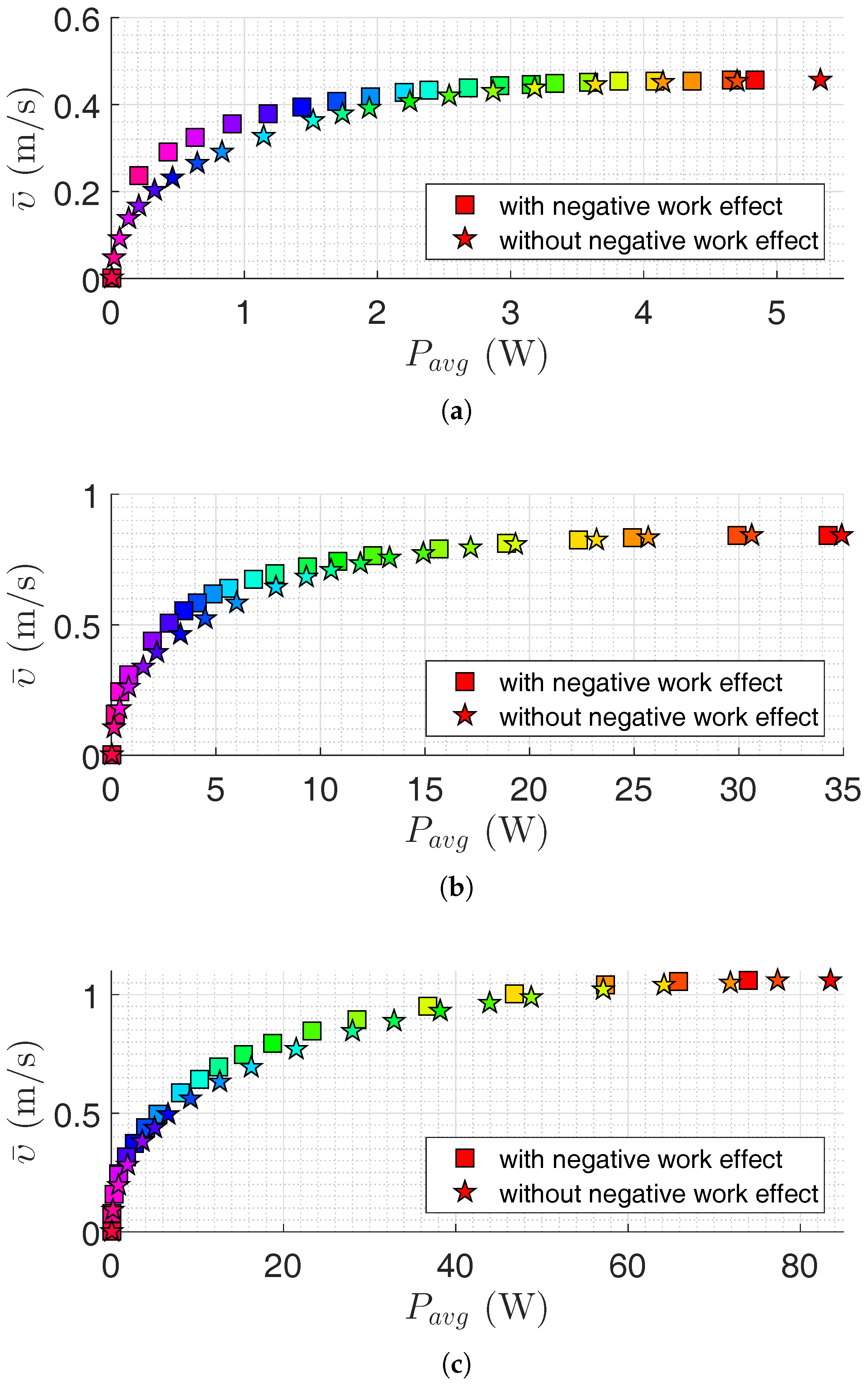
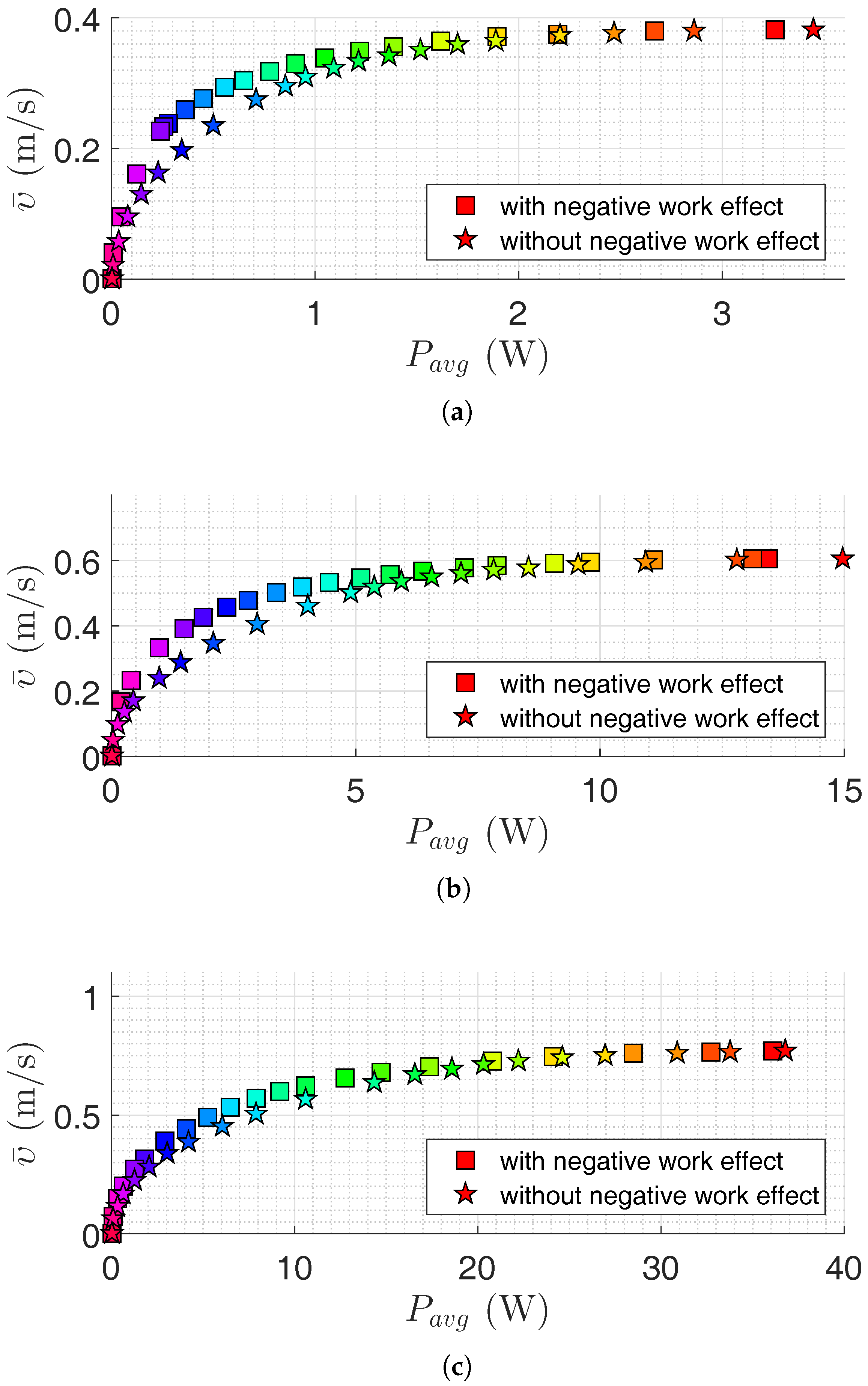
In this section, the results of motion efficiency optimization of underwater snake robots are presented for both lateral undulation and eel-like motion patterns. The parameters of the robot are specified in Section 4.1. Pareto fronts are presented in Figure 4 and Figure 5 for a different number of links for lateral undulation and eel-like motion pattern, respectively. In these figures, we also investigate the negative work effect in the calculation of average power consumption (see Equations (16) and (17)). Figure 6, Figure 7, Figure 8 and Figure 9 show Pareto optimal gait parameters of the sinusoidal motion pattern vs. Pareto optimal average power consumption and achieved forward velocity. As it was expected, the robot consumed the maximum power when moving with the highest forward velocity, while zero power is consumed when the robot is not moving (i.e., for zero forward velocity). To discuss some of the observations, selected Pareto optimal points are compared in Table 3, Table 4, Table 5 and Table 6. The maximum achieved forward velocities and corresponding optimal parameters for different numbers of links are presented in these tables. The maximum forward velocity for the underwater snake robot with lateral undulation motion pattern is equal to m/s, m/s, and m/s, respectively, for a number of links equal to 5, 10, and 20. The maximum average power consumption considering the negative work effect is equal to W, W, and W for a number of links equal to , and 20, respectively. If we neglect negative work effect the maximum average power consumption is increased to W, W, and W, respectively, for a number of links equal to 5, 10, and 20. The increment of average power consumption as a result of disregarding negative work effect is equal to 10.35%, 1.97% and 12.76%. As expected, the maximum forward velocity for eel-like motion pattern is lower than that of snake robot with a lateral undulation pattern: m/s for , m/s for , m/s for . The maximum average power consumption for eel-like motion pattern considering negative work effect is equal to W, W, W for and 20, respectively. In the case of disregarding negative work effect, the maximum power consumption is changed to W, W and W, for a number of links equal to 5, 10, and 20, respectively. This means neglecting negative work effect results in 5.83%, 11.31% and 1.94% increase of power consumption for and 20, respectively. One can observe from all Pareto optimal points of both motion patterns, the robot consumes more energy when the negative work effect is not considered. It is important to consider this observation in the development of underwater snake robots.
We can also compare the maximum values of objective functions in terms of the number of links. For the lateral undulation motion pattern, 82.61% and 26.19% increases in the forward velocity are achieved by doubling the number of links from 5 to 10 and from 10 to 20, respectively. The penalty of these velocity increments is an increase of power consumption of approximately 7 and 2.2 times, respectively. Similar results are observed for the eel-like motion pattern. We have approximately 4.1 and 2.7 times increment in the average power consumption for 57.89% and 28.33% increment in the achieved forward velocity, respectively, by multiplying the number of links by a factor of 2. In the case of disregarding negative work effect, one can observe that the robot with 10 links consumes approximately 6.55 and 2.4 times more power than a robot with 5 links for lateral undulation and eel-like motion pattern, respectively. Moreover, a robot with 20 links consumes 4.4 and 2.5 times more power than a robot with 10 links, for lateral undulation and eel-like motion patterns, respectively. Hence, the number of links is directly connected to the efficiency of the underwater snake robots. Therefore, it is important to also consider the number of links as a new optimization variable in the problem. The optimum value of the number of links gives useful inputs in the design stage and the implementation of the swimming snake robots.
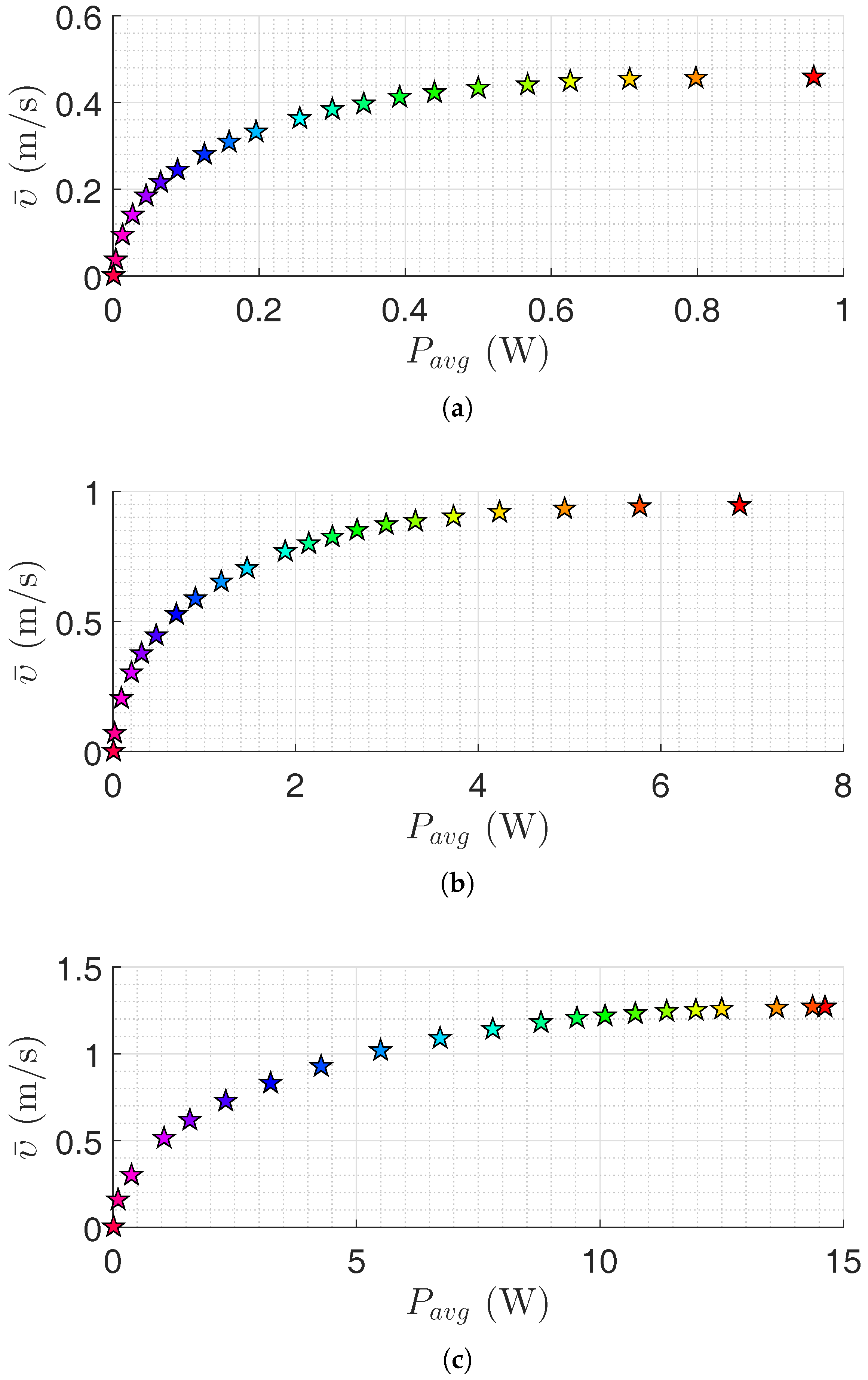
Figure 4 and Figure 5 show that it is possible to obtain a significant decrease in the consumed power by a slight decrease in the achieved forward velocity. This observation is also clearly presented in Table 3, Table 4, Table 5 and Table 6. For the lateral undulation motion pattern of the snake robot with five links, 44.51% (or ) decrease in the average power consumption leads to a slight decrease of (or ) in the forward velocity. Similarly for the eel-like motion pattern, by decreasing 42.02% (or ) in the power consumption, we have (or ) decrease in the forward velocity. Table 5 and Table 6 give similar results for the case that the negative work effect is not considered. In this case, we see that it is possible to decrease the consumed power about 40.34% (or ) and 45.22% (or ) for lateral undulation and eel-like motion pattern, respectively. Similar results are also obtained for an underwater snake robot with 10 and 20 links. For the robot with 10 links, we can observe that the robot can consume (or ) and (or ) less power by reducing the forward velocity by (or ) and (or ), for lateral undulation and eel-like motion, respectively. If we neglect negative work effect, the robot consumes (or ) less power for lateral undulation and (or ) less power for eel-like motion pattern. For the robot with 20 links with lateral undulation pattern, we can reduce the power consumption by and by reducing the achieved forward velocity by and , respectively. For the eel-like motion pattern, Figure 5c shows that the average power consumption can be reduced by 42.32% and 59.23% while the corresponding forward velocity is decreased only by 5.19% and 11.69%. If we calculate the power consumption without considering negative work effect, for the mentioned decrease of the forward velocity we can save and power for lateral undulation, and and power for eel-like motion pattern. In conclusion, this observation may attract the attention of designers to study Pareto fronts in order to reduce power consumption significantly while decreasing the corresponding forward velocity slightly.
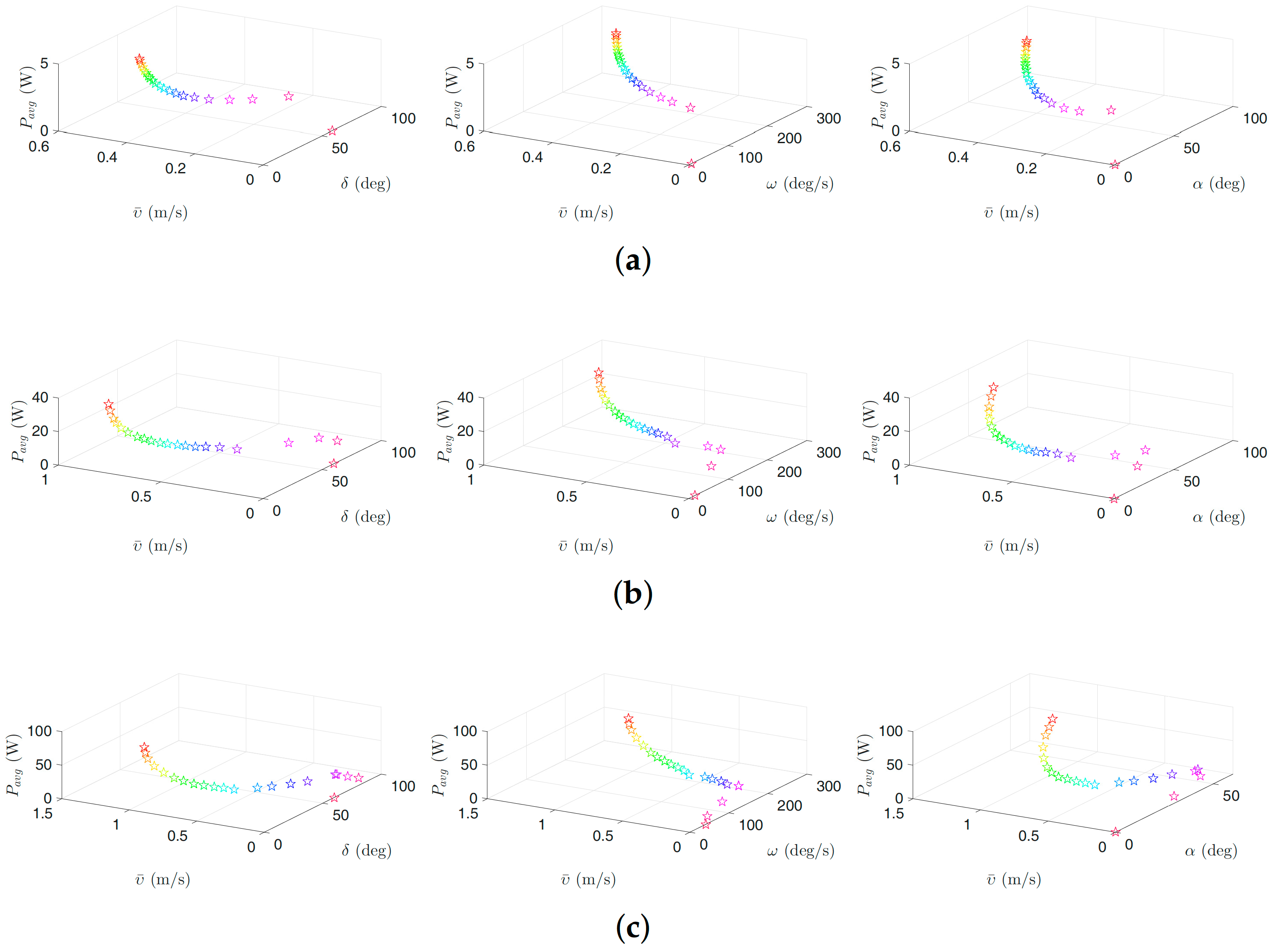
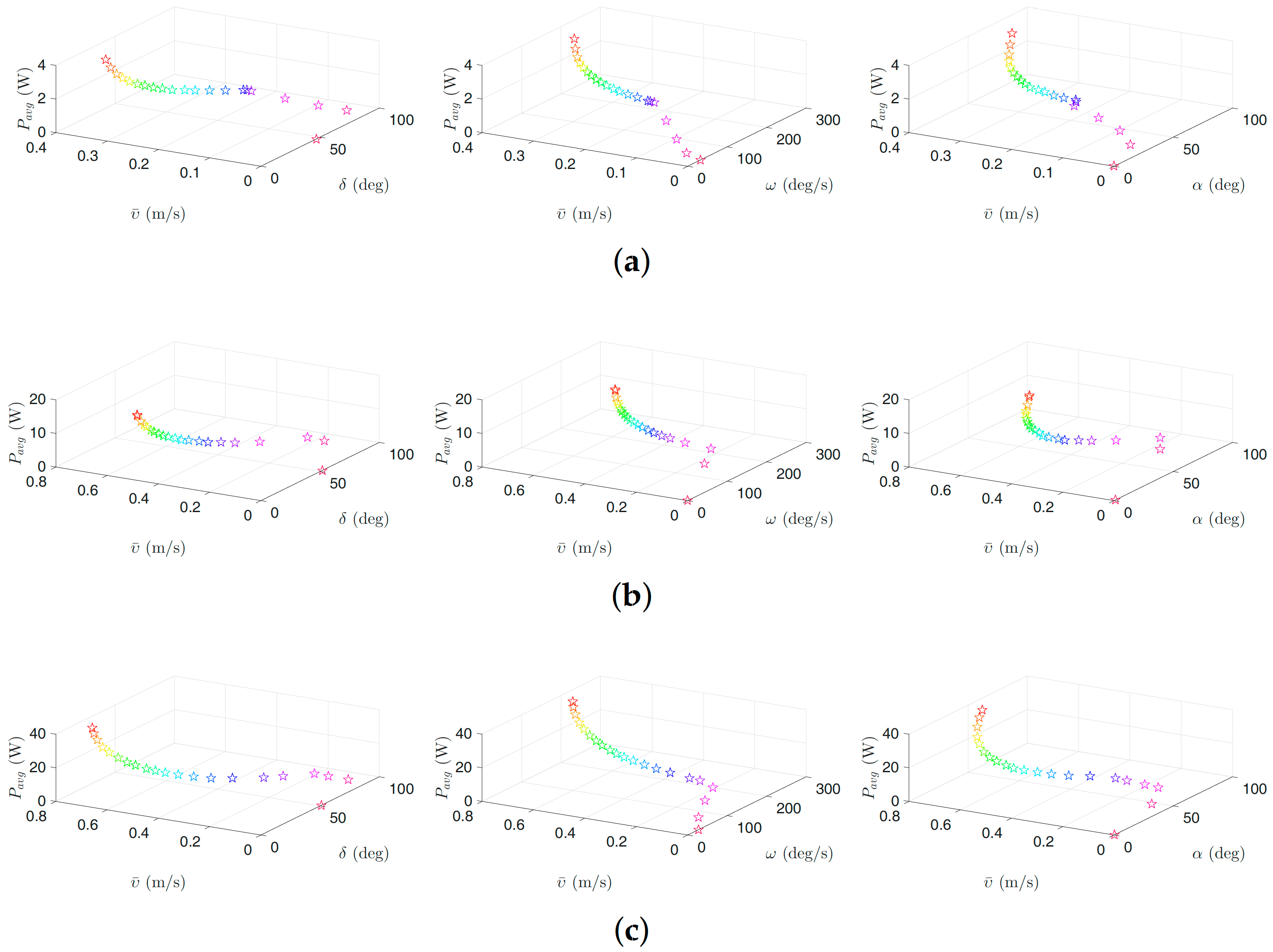
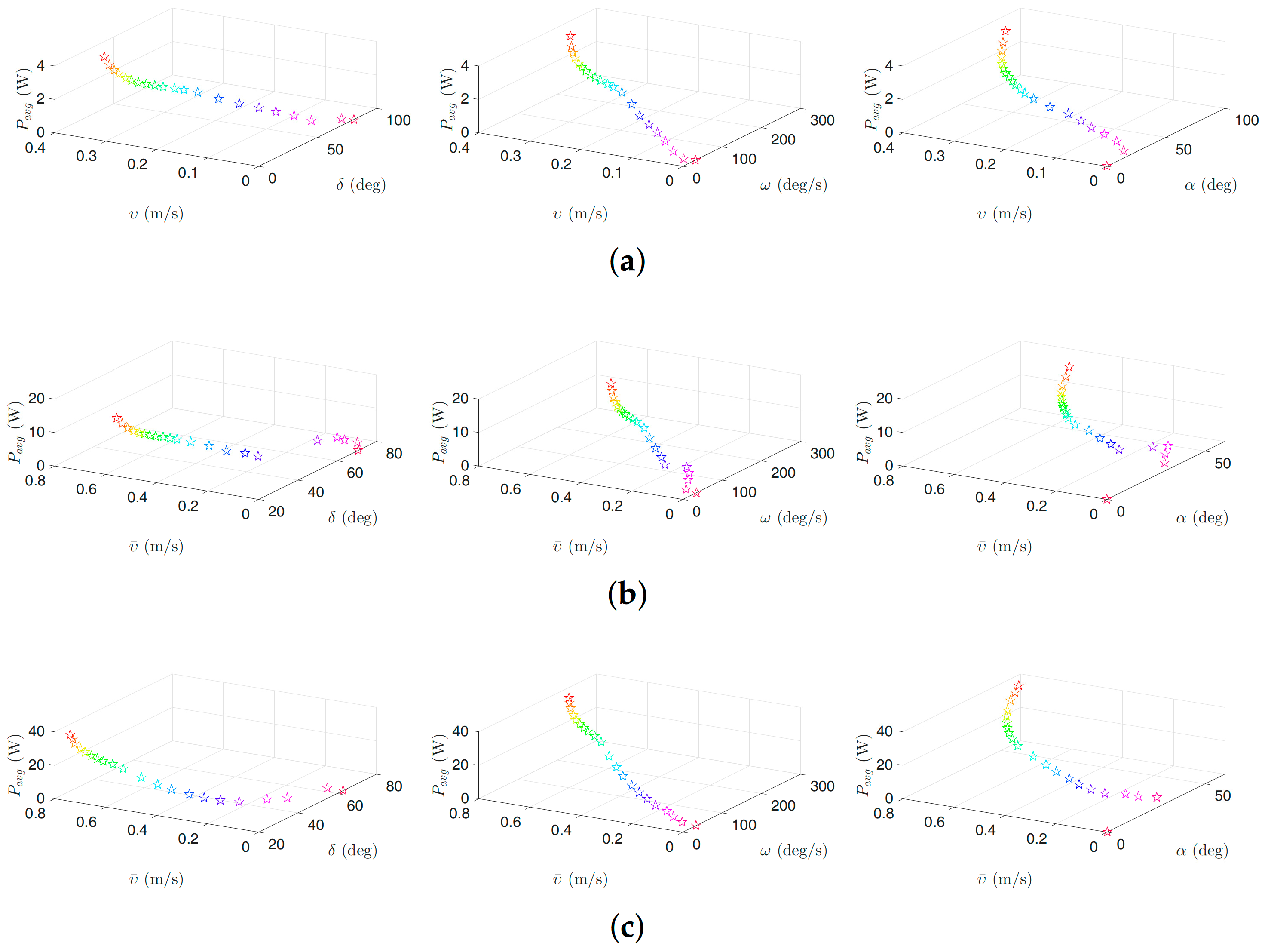
Figure 6, Figure 7, Figure 8 and Figure 9 present the inverse correlation of the parameter and the forward velocity or the power consumption. Furthermore, we can also observe in Figure 6 that, for the case of considering the negative work effect, the gait parameter takes values in the range of , and for all optimization trials for the underwater snake robot studied in this paper with , and links, respectively, for lateral undulation. Figure 7 shows that the range of change of the gait parameter is equal to , and for a robot with , and links, for an eel-like motion pattern. The values of the phase shift parameter are in the range of , , and , , for the robot with , , links for lateral undulation and an eel-like motion pattern, respectively. In the case that the negative work effect is not considered, the maximum amplitude for lateral undulation pattern is in the range of , , and when the number of links is, respectively, equal to 5, 10, and 20. For the eel-like motion pattern, the range of is equal to , , and , respectively, for , and 20. For lateral undulation pattern, the phase shift changes in the range of , , and for , and 20, respectively. For the eel-like motion pattern, the range of phase shift is equal to , , and for , and 20, respectively.
We can also observe that the maximum forward velocity is achieved using the maximum values of /s for all the cases, while the obtained values of the amplitude, , and the phase-shift, , are different for the investigated motion patterns. These observations are useful for both control design purposes and defining the range of the gait parameters for solving the optimization problem more precisely in the future.
4.4. Results for Land-Based Snake Robots
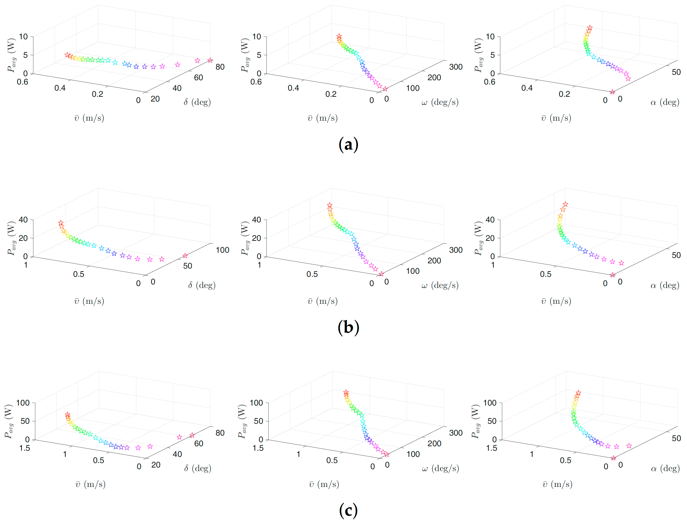
In this section, optimization results for the land-based snake robots are discussed. The motion pattern is considered lateral undulation which is the most common motion pattern for land-based snake robots [1]. Figure 10 presents the Pareto fronts (trade off curves) for different numbers of links. Figure 11 illustrates the Pareto optimal average power consumption and forward velocity versus corresponding optimal gait parameters. Table 7 summarizes a selected number of Pareto optimal objective functions and related Pareto optimal gait parameters. For a land-based snake robot with 5, 10, and 20 links, the maximum forward velocity is equal to m/s, m/s, and , respectively, and the corresponding average power consumption is equal to , , and , respectively. This means increasing the number of links from 5 to 10 leads to approximately a increase in forward velocity, while the average power consumption is increased approximately seven times. We observe about increment in the forward velocity by changing the number of links from 10 to 20, and as a result the average power consumption is increased approximately two times. From this table, we notice that the optimal frequency related to the maximum forward velocity is equal to /s for different numbers of links. The optimal maximum amplitude is equal to , , and , respectively, for 5, 10 and 20 links. The optimal phase shift for 5, 10, and 20 links is defined equal to , , and , respectively.
We observe from Figure 10 that one can obtain a significant decrease in the average power consumption as a trade-off for a negligible decrease in the achieved forward velocity. This trade-off is also stated in Table 7. For a snake robot with 5 links, the table gives a 40.79% decrease of the average power consumption (from W to W) results in just decrease in the forward velocity ( m/s to m/s). Another alternative is to decrease the average power consumption from W to W (about 54% increment) by decreasing the forward velocity from m/s to m/s (8.69% decrease). Similar results are also stated for a robot with 10 and 20 links. For a snake robot with 10 links, we see that the robot is able to consume and less power by reducing the forward velocity by and , respectively. Similarly, for a snake robot with 20 links, we can reduce the power consumption by and by reducing the achieved forward velocity by and , respectively. Consequently, based on these results, the operators can select the gait parameters in a way that would result in a significant decrease of the consumed power, while giving only a slight decrease of the forward velocity.
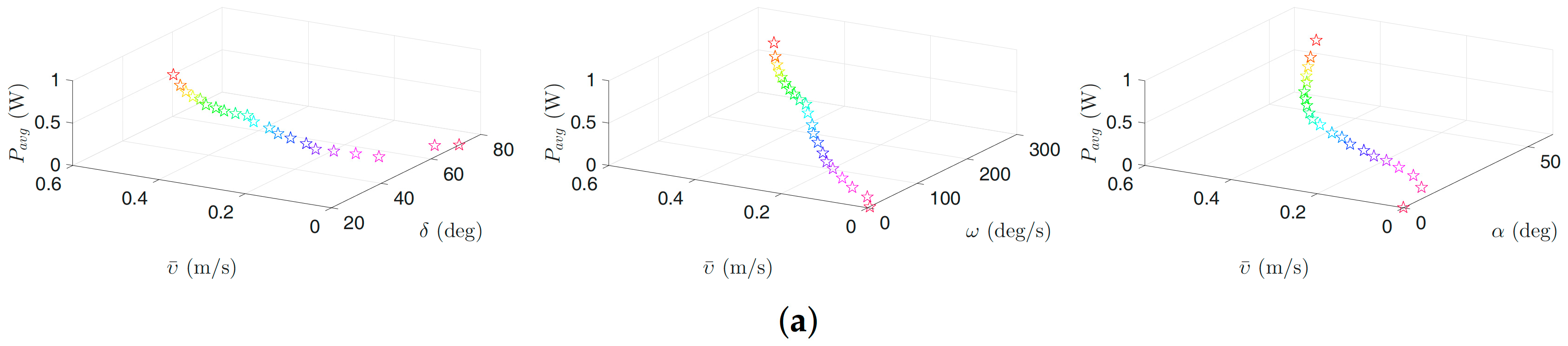
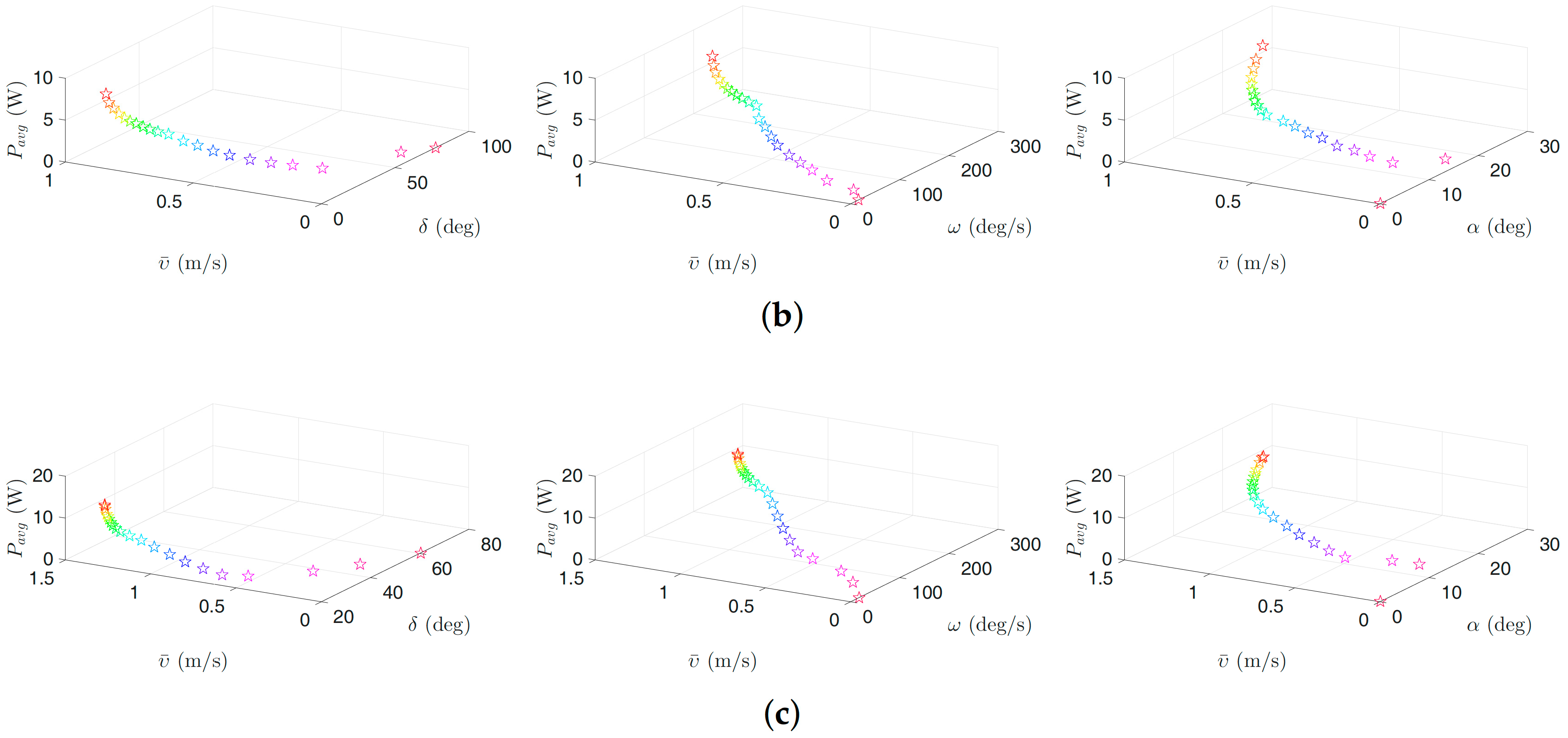
As we can see in Figure 11, the forward velocity and the power consumption decrease when the value of the gait parameter increases. In addition, we observe that the optimal value of the gait parameter is greater than 14, 17 and 13 in all weighting sets for the robot with , and links, respectively. In particular, the gait parameter takes values in the range of , and for all optimization trials for the land-based snake robot studied in this paper with , and links, respectively. The values of the phase shift parameter are in the range of , and for the robot with , and links, respectively. The maximum forward velocity is achieved for the maximum values of /s. Note that these insights are essential for control design purposes for bio-inspired snake robots. Furthermore, they can be used to customize the necessary constraints for future optimization investigations.
Remark 3.
Note that the Pareto fronts illustrated in Figure 4, Figure 5 and Figure 10 constitute an informative visualization tool, which helps control system designers to get full information about objective values (power consumption and velocity) and objective tradeoffs. Consequently, depending on the control objectives and the available power of the robot, the operators or designers of bio-inspired snake robots can choose the optimal operational point using the Pareto fronts. Afterward, the corresponding gait parameters can be obtained.
Remark 4.
We observe in Table 3, Table 4, Table 5, Table 6 and Table 7 that the frequency parameter ω tends to stay at the maximum value. Therefore, there is a possibility to reduce the dimension of the search space, , to 2 by eliminating ω from the decision variables and setting this parameter equal to the maximum possible value. This observation can also be embedded in the design of the bio-inspired snake robots. This means one should consider the maximum possible value for the frequency during actuation mechanism selection. As a result, it motivates designers to investigate possible high frequency actuation solutions in control and design of underwater and land-based snake robot.
5. Conclusions
A general multi-objective optimization framework was presented in this paper. The proposed framework was applied to study the locomotion efficiency for both swimming and land-based snake robots with different numbers of links. The optimal gait parameters were obtained for different configurations of the snake robots. The proposed optimization scheme is general in the sense that it can be used to study the locomotion efficiency for robotic systems using undulatory motion patterns. Using this framework, locomotion efficiency optimization was analyzed for both land-based snake robots moving according to the gait pattern lateral undulation, and for swimming snake robots, using lateral undulation and eel-like motion. In the latter case, the negative work effect was also taken into account. In particular, the energy efficiency of the underwater snake robots was studied using two different equations to calculate power consumption. In the first case, the absolute value of the theoretical joint power was considered as the power consumption, while, in the second case, the benefit of the negative work effect was also considered, i.e., taking into account that the robot is able to recover energy and thus calculating the power consumption using the net joint power. Optimization results for the land-based snake robot were presented considering only the absolute values of the theoretical joint power because of the energy consumption of the ground friction, which does not give a negative work effect. PSO was chosen as a suitable optimization algorithm to acquire the Pareto optimal solutions taking into account the trade-offs between the consumed power and the achieved forward velocity. From the obtained Pareto fronts, we concluded that improving energy efficiency corresponds to the decrements of the forward velocity. Consequently, depending on the control objectives and the available power of the robot, the operators or designers of bio-inspired snake robots can choose the optimal operational point using the Pareto fronts as an informative tool. Furthermore, based on the multi-objective optimization study, we managed to acquire useful insights regarding the optimal values of the gait parameters for both land-based and swimming snake robots. These observations are important to consider in the control and design of snake robots. Investigating the locomotion efficiency of bio-inspired snake robot using other types of sinusoidal motion patterns will be the subject of future work. It is likely that other design parameters could also improve the motion efficiency of the snake robots, and we plan to study the effect of these in future work. Moreover, the proposed optimization framework can also be used for optimizing gaits of biped robots by introducing newly revised optimization variables.
Acknowledgments
Research partly funded by VISTA a basic research program in collaboration between The Norwegian Academy of Science and Letters, and Statoil, and partly supported by the Research Council of Norway through its Centres of Excellence funding scheme, project no. 223254-NTNU AMOS.
Author Contributions
The authors have contributed equally to this work.
Conflicts of Interest
The authors declare no conflict of interest.
References
- Liljebäck, P.; Pettersen, K.Y.; Stavdahl, Ø.; Gravdahl, J.T. Snake Robots: Modelling, Mechatronics, and Control; Springer: London, UK, 2013. [Google Scholar]
- Gray, J. Studies in Animal Locomotion. J. Exp. Biol. 1933, 10, 88–104. [Google Scholar]
- Hirose, S. Biologically Inspired Robots: Snake-Like Locomotors and Manipulators; Oxford University Press: Oxford, UK, 1993. [Google Scholar]
- Colgate, J.; Lynch, K. Mechanics and control of swimming: A review. IEEE J. Ocean. Eng. 2004, 29, 660–673. [Google Scholar] [CrossRef]
- Fossen, T.I. Handbook of Marine Craft Hydrodynamics and Motion Control; John Wiley & Sons, Ltd.: Hoboken, NJ, USA, 2011. [Google Scholar]
- Kelasidi, E.; Pettersen, K.Y.; Gravdahl, J.T.; Liljebäck, P. Modeling of underwater snake robots. In Proceedings of the IEEE International Conference on Robotics and Automation (ICRA), Hong Kong, China, 31 May–7 June 2014; pp. 4540–4547. [Google Scholar]
- Boyer, F.; Porez, M.; Khalil, W. Macro-continuous computed torque algorithm for a three-dimensional eel-like robot. IEEE Trans. Robot. 2006, 22, 763–775. [Google Scholar] [CrossRef]
- Wiens, A.; Nahon, M. Optimally efficient swimming in hyper-redundant mechanisms: Control, design, and energy recovery. Bioinspir. Biomim. 2012, 7, 046016. [Google Scholar] [CrossRef] [PubMed]
- Khalil, W.; Gallot, G.; Boyer, F. Dynamic modeling and simulation of a 3-D serial eel-like robot. IEEE Trans. Syst. Man Cybern. Part C Appl. Rev. 2007, 37, 1259–1268. [Google Scholar] [CrossRef]
- Tesch, M.; Schneider, J.; Choset, H. Expensive multiobjective optimization and validation with a robotics application. In Proceedings of the Neural Information Processing Systems: Workshop on Bayesian Optimization & Decision Making, Lake Tahoe, NV, USA, 7 December 2012. [Google Scholar]
- Hasanzadeh, S.; Tootoonchi, A.A. Ground adaptive and optimized locomotion of snake robot moving with a novel gait. Auton. Robots 2010, 28, 457–470. [Google Scholar] [CrossRef]
- Crespi, A.; Ijspeert, A.J. Online optimization of swimming and crawling in an amphibious snake robot. IEEE Trans. Robot. 2008, 24, 75–87. [Google Scholar] [CrossRef]
- Kelasidi, E.; Pettersen, K.Y.; Gravdahl, J.T. Energy efficiency of underwater snake robot locomotion. In Proceedings of the 23th Mediterranean Conference on Control Automation (MED), Torremolinos, Spain, 16–19 June 2015; pp. 1124–1131. [Google Scholar]
- Kelasidi, E.; Pettersen, K.Y.; Gravdahl, J.T. Energy efficiency of underwater robots. In Proceedings of the 10th IFAC Conference on Manoeuvring and Control of Marine Craft (MCMC), Copenhagen, Denmark, 24–26 August 2015; pp. 152–159. [Google Scholar]
- Kelasidi, E.; Liljebäck, P.; Pettersen, K.Y.; Gravdahl, J.T. Experimental investigation of efficient locomotion of underwater snake robots for lateral undulation and eel-like motion patterns. Robot. Biomim. 2015, 2, 1–27. [Google Scholar] [CrossRef] [PubMed] [Green Version]
- Kelasidi, E.; Jesmani, M.; Pettersen, K.Y.; Gravdahl, J.T. Multi-objective optimization for efficient motion of underwater snake robots. Artif. Life Robot. 2016, 21, 1–12. [Google Scholar] [CrossRef]
- McIsaac, K.; Ostrowski, J. Motion planning for anguilliform locomotion. IEEE Trans. Robot. Autom. 2003, 19, 637–652. [Google Scholar] [CrossRef]
- Taylor, G. Analysis of the swimming of long and narrow animals. Proc. R. Soc. Lond. Ser. A Math. Phys. Sci. 1952, 214, 158–183. [Google Scholar] [CrossRef]
- Lighthill, M.J. Large-amplitude elongated-body theory of fish locomotion. Proc. R. Soc. Lond. Ser. B. Biol. Sci. 1971, 179, 125–138. [Google Scholar] [CrossRef]
- Chen, J.; Friesen, W.O.; Iwasaki, T. Mechanisms underlying rhythmic locomotion: Body-fluid interaction in undulatory swimming. J. Exp. Biol. 2011, 214, 561–574. [Google Scholar] [CrossRef] [PubMed]
- Kelasidi, E.; Pettersen, K.Y.; Liljebäck, P.; Gravdahl, J.T. Integral line-of-sight for path-following of underwater snake robots. In Proceedings of the IEEE Multi-Conference on Systems and Control, Juan Les Antibes, France, 8–10 October 2014; pp. 1078–1085. [Google Scholar]
- Kelasidi, E.; Liljebäck, P.; Pettersen, K.Y.; Gravdahl, J.T. Integral line-of-sight guidance for path following control of underwater snake robots: Theory and experiments. IEEE Trans. Robot. 2014, 33, 610–628. [Google Scholar] [CrossRef]
- Koziel, S.; Yang, X.S. (Eds.) Computational Optimization, Methods and Algorithms; Springer: Berlin/Heidelberg, Germany, 2011; Volume 356. [Google Scholar]
- Kuo, P.D.; Grierson, D. Genetic algorithm optimization of escape and normal swimming gaits for a hydrodynamical model of carangiform locomotion. In Proceedings of the Genetic and Evolutionary Computation Conference (GECCO), Chicago, IL, USA, 12–16 July 2003; pp. 170–177. [Google Scholar]
- Kern, S.; Koumoutsakos, P. Simulations of optimized anguilliform swimming. J. Exp. Biol. 2006, 209, 4841–4857. [Google Scholar] [CrossRef] [PubMed]
- Kennedy, J.; Eberhart, R. Particle swarm optimization. In Proceedings of the IEEE International Conference on Neural Networks, Perth, Australia, 27 November–1 December 1995; pp. 1942–1948. [Google Scholar]
- Kober, J.; Bagnell, J.A.; Peters, J. Reinforcement learning in robotics: A survey. Int. J. Robot. Res. 2013, 32, 1238–1274. [Google Scholar] [CrossRef]
- Di Mario, E.; Talebpour, Z.; Martinoli, A. A comparison of PSO and reinforcement learning for multi-robot obstacle avoidance. In Proceedings of the IEEE Congress on Evolutionary Computation (CEC), Cancun, Mexico, 20–23 June 2013; pp. 149–156. [Google Scholar]
- Ariizumi, R.; Tesch, M.; Kato, K.; Choset, H.; Matsuno, F. Multiobjective optimization based on expensive robotic experiments under heteroscedastic noise. IEEE Trans. Robot. 2017, 33, 468–483. [Google Scholar] [CrossRef]
- Ariizumi, R.; Matsuno, F. Dynamic analysis of three snake robot gaits. IEEE Trans. Robot. 2017, 33, 1075–1087. [Google Scholar] [CrossRef]
- Kelasidi, E.; Pettersen, K.Y.; Gravdahl, J.T. Stability analysis of underwater snake robot locomotion based on averaging theory. In Proceedings of the IEEE International Conference on Robotics and Biomimetics (ROBIO), Bali, Indonesia, 5–10 December 2014; pp. 574–581. [Google Scholar]
- Pareto, V. Manual of Political Economy; A. M. Kelley: New York, NY, USA, 1906. [Google Scholar]
- Liljebäck, P.; Stavdahl, Ø.; Pettersen, K.; Gravdahl, J. Mamba—A waterproof snake robot with tactile sensing. In Proceedings of the International Conference on Intelligent Robots and Systems (IROS), Chicago, IL, USA, 14–18 September 2014; pp. 294–301. [Google Scholar]
- Jesmani, M.; Bellout, M.C.; Hanea, R.; Foss, B. Well placement optimization subject to realistic field development constraints. Comput. Geosci. 2016, 20, 1185–1209. [Google Scholar] [CrossRef]
- Wetter, M. GenOpt—A generic optimization program. In Proceedings of the 7th International Conference of the International Building Performance Simulation Association Conference (IBPSA), Rio de Janeiro, Brazil, 13–15 August 2001; pp. 601–608. [Google Scholar]
- Parsopoulos, K.; Vrahatis, M. Recent approaches to global optimization problems through particle swarm optimization. Nat. Comput. 2002, 1, 235–306. [Google Scholar] [CrossRef]
- Carlisle, A.; Dozier, G. An off-the-shelf PSO. In Proceedings of the Workshop on Particle Swarm Optimization, Indianapolis, IN, USA, 6–7 April 2001. [Google Scholar]
Figure 1.
Kinematic parameters of the underwater snake robot.

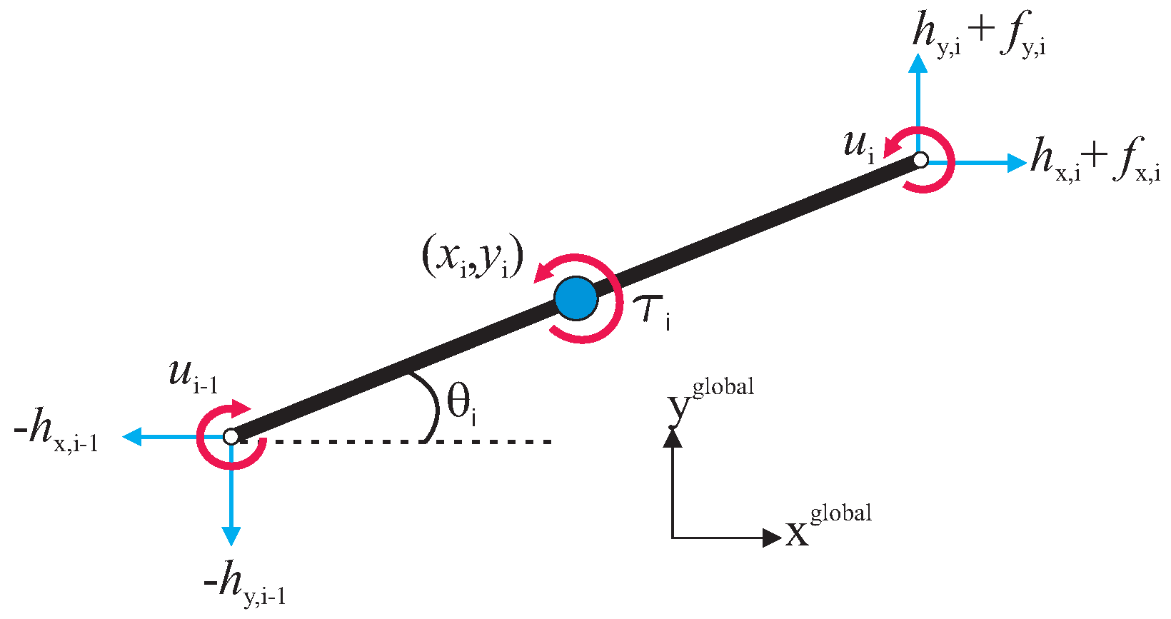
Figure 2.
Forces and torques acting on each link of the underwater snake robot.

Figure 3.
Illustration of the optimization framework.

Figure 4.
Pareto front for the USR using the lateral undulation motion pattern: (a) Pareto front for robot with links; (b) Pareto front for robot with links; and (c) Pareto front for robot with links. Colors illustrate different weights of the objective functions.
Figure 4.
Pareto front for the USR using the lateral undulation motion pattern: (a) Pareto front for robot with links; (b) Pareto front for robot with links; and (c) Pareto front for robot with links. Colors illustrate different weights of the objective functions.

Figure 5.
Pareto front for the USR using the eel-like motion pattern: (a) Pareto front for robot with links; (b) Pareto front for robot with links; and (c) Pareto front for robot with links. Colors illustrate different weights of the objective functions.
Figure 5.
Pareto front for the USR using the eel-like motion pattern: (a) Pareto front for robot with links; (b) Pareto front for robot with links; and (c) Pareto front for robot with links. Colors illustrate different weights of the objective functions.

Figure 6.
Optimal gait parameters for the lateral undulation motion pattern for the USR, considering the negative work effect: (a) 3D plots of optimal gait parameters for robot with links; (b) 3D plots of optimal gait parameters for robot with links; and (c) 3D plots of optimal gait parameters for robot with links. Colors illustrate different weights of the objective functions.

Figure 7.
Optimal gait parameters for the eel-like motion pattern for the USR, considering the negative work effect: (a) 3D plots of optimal gait parameters for robot with links; (b) 3D plots of optimal gait parameters for robot with links; and (c) 3D plots of optimal gait parameters for robot with links. Colors illustrate different weights of the objective functions.

Figure 8.
Optimal gait parameters for the lateral undulation motion pattern for the USR, without considering the negative work effect: (a) 3D plots of optimal gait parameters for robot with links; (b) 3D plots of optimal gait parameters for robot with links; and (c) 3D plots of optimal gait parameters for robot with links. Colors illustrate different weights of the objective functions.

Figure 9.
Optimal gait parameters for the eel-like motion pattern for the USR, without considering the negative work effect: (a) 3D plots of optimal gait parameters for robot with links; (b) 3D plots of optimal gait parameters for robot with links; and (c) 3D plots of optimal gait parameters for robot with links. Colors illustrate different weights of the objective functions.

Figure 10.
Pareto front for the land-based snake robot using the lateral undulation motion pattern: (a) Pareto front for robot with links; (b) Pareto front for robot with links; and (c) Pareto front for robot with links. Colors illustrate different weights of the objective functions.
Figure 10.
Pareto front for the land-based snake robot using the lateral undulation motion pattern: (a) Pareto front for robot with links; (b) Pareto front for robot with links; and (c) Pareto front for robot with links. Colors illustrate different weights of the objective functions.

Figure 11.
Optimal gait parameters for the lateral undulation motion pattern for the land-based snake robot: (a) 3D plots of optimal gait parameters for robot with links; (b) 3D plots of optimal gait parameters for robot with links; and (c) 3D plots of optimal gait parameters for robot with links. Colors illustrate different weights of the objective functions.


Table 1.
Definition of mathematical terms.
| Symbol | Description | Vector |
|---|---|---|
| n | The number of links | - |
| l | The half length of a link | - |
| m | Mass of each link | - |
| J | Moment of inertia of each link | - |
| Angle between link i and the global axis | ||
| Angle of joint i | ||
| Global coordinates of the CM of link i | ||
| Global coordinates of the CM of the robot | ||
| Actuator torque of joint between link i and link | ||
| Actuator torque of joint between link i and link | ||
| Fluid force on link i in the direction | ||
| Fluid force on link i in the direction | ||
| Fluid torque on link i | ||
| Ground friction force on link i in the direction | ||
| Ground friction force on link i in the direction | ||
| Joint constraint force in the direction on link i from link | ||
| Joint constraint force in the direction on link i from link | ||
| Joint constraint force in the direction on link i from link | ||
| Joint constraint force in the direction on link i from link |
Table 2.
Range of the parameters of the sinusoidal motion pattern.
| n | (/s) | |||||
|---|---|---|---|---|---|---|
| 5 | 0 | 0 | 210 | 0 | ||
| 10 | 0 | 0 | 210 | 0 | ||
| 20 | 0 | 0 | 210 |
Table 3.
Multi-objective optimization results for the lateral undulation motion pattern for the USR with different numbers of links, considering the negative work effect.
Table 3.
Multi-objective optimization results for the lateral undulation motion pattern for the USR with different numbers of links, considering the negative work effect.
| n | (deg) | (deg/s) | (deg) | (m/s) | (W) |
|---|---|---|---|---|---|
| 5 | 57.68 | 210 | 26.82 | 0.46 | 4.83 |
| 5 | 52.33 | 210 | 35.65 | 0.44 | 2.68 |
| 5 | 51.68 | 210 | 39.33 | 0.43 | 2.20 |
| 10 | 44.01 | 210 | 15.14 | 0.84 | 34.25 |
| 10 | 34.92 | 210 | 20.32 | 0.81 | 18.92 |
| 10 | 33.42 | 210 | 22.97 | 0.79 | 15.69 |
| 20 | 41.21 | 210 | 20.00 | 1.06 | 74.01 |
| 20 | 32.45 | 210 | 21.73 | 1.00 | 46.74 |
| 20 | 29.16 | 210 | 24.01 | 0.95 | 36.75 |
Table 4.
Multi-objective optimization results for the eel-like motion pattern for the USR with different numbers of links, considering the negative work effect.
Table 4.
Multi-objective optimization results for the eel-like motion pattern for the USR with different numbers of links, considering the negative work effect.
| n | (deg) | (deg/s) | (deg) | (m/s) | (W) |
|---|---|---|---|---|---|
| 5 | 79.21 | 210 | 34.23 | 0.38 | 3.26 |
| 5 | 72.04 | 210 | 43.73 | 0.37 | 1.89 |
| 5 | 69.69 | 210 | 50.09 | 0.36 | 1.39 |
| 10 | 59.24 | 210 | 26.20 | 0.60 | 13.44 |
| 10 | 52.61 | 210 | 33.47 | 0.58 | 7.88 |
| 10 | 51.33 | 210 | 36.69 | 0.57 | 6.37 |
| 20 | 55.13 | 210 | 23.97 | 0.77 | 36.08 |
| 20 | 43.83 | 210 | 29.48 | 0.73 | 20.81 |
| 20 | 42.03 | 210 | 33.86 | 0.68 | 14.71 |
Table 5.
Multi-objective optimization results for the lateral undulation motion pattern for the USR with different numbers of links, without considering the negative work effect.
Table 5.
Multi-objective optimization results for the lateral undulation motion pattern for the USR with different numbers of links, without considering the negative work effect.
| n | (deg) | (deg/s) | (deg) | (m/s) | (W) |
|---|---|---|---|---|---|
| 5 | 58.05 | 210 | 26.68 | 0.46 | 5.33 |
| 5 | 51.16 | 210 | 35.17 | 0.44 | 3.18 |
| 5 | 48.14 | 210 | 39.34 | 0.42 | 2.54 |
| 10 | 44.02 | 210 | 15.17 | 0.84 | 34.92 |
| 10 | 34.76 | 210 | 20.98 | 0.81 | 19.31 |
| 10 | 32.26 | 210 | 24.68 | 0.77 | 14.92 |
| 20 | 40.96 | 210 | 20.00 | 1.06 | 83.45 |
| 20 | 34.03 | 210 | 21.07 | 1.02 | 57.09 |
| 20 | 29.81 | 210 | 22.64 | 0.97 | 43.92 |
Table 6.
Multi-objective optimization results for the eel-like motion pattern for the USR with different numbers of links, without considering the negative work effect.
Table 6.
Multi-objective optimization results for the eel-like motion pattern for the USR with different numbers of links, without considering the negative work effect.
| n | (deg) | (deg/s) | (deg) | (m/s) | (W) |
|---|---|---|---|---|---|
| 5 | 79.21 | 210 | 34.23 | 0.38 | 3.45 |
| 5 | 69.37 | 210 | 45.38 | 0.37 | 1.89 |
| 5 | 66.13 | 210 | 50.18 | 0.35 | 1.52 |
| 10 | 59.24 | 209.98 | 26.20 | 0.60 | 14.96 |
| 10 | 51.83 | 210 | 34.41 | 0.58 | 8.53 |
| 10 | 50.17 | 209.98 | 37.48 | 0.56 | 7.14 |
| 20 | 55.13 | 210 | 23.97 | 0.77 | 36.78 |
| 20 | 43.49 | 210 | 29.28 | 0.73 | 22.21 |
| 20 | 40.39 | 209.95 | 31.23 | 0.70 | 18.62 |
Table 7.
Multi-objective optimization results for the land-based snake robot with different numbers of links.
Table 7.
Multi-objective optimization results for the land-based snake robot with different numbers of links.
| n | (deg) | (deg/s) | (deg) | (m/s) | (W) |
|---|---|---|---|---|---|
| 5 | 44.32 | 210 | 36.04 | 0.46 | 0.96 |
| 5 | 37.81 | 210 | 43.78 | 0.44 | 0.57 |
| 5 | 33.92 | 210 | 46.78 | 0.42 | 0.44 |
| 10 | 25.27 | 210 | 18.02 | 0.94 | 6.86 |
| 10 | 20.87 | 210 | 23.29 | 0.90 | 3.73 |
| 10 | 19.61 | 210 | 25.57 | 0.87 | 3.00 |
| 20 | 22.22 | 210 | 20.00 | 1.27 | 14.62 |
| 20 | 15.87 | 210 | 20.02 | 1.21 | 9.53 |
| 20 | 14.73 | 210 | 21.38 | 1.14 | 7.80 |
© 2018 by the authors. Licensee MDPI, Basel, Switzerland. This article is an open access article distributed under the terms and conditions of the Creative Commons Attribution (CC BY) license (http://creativecommons.org/licenses/by/4.0/).
Share and Cite
MDPI and ACS Style
Kelasidi, E.; Jesmani, M.; Pettersen, K.Y.; Gravdahl, J.T. Locomotion Efficiency Optimization of Biologically Inspired Snake Robots. Appl. Sci. 2018, 8, 80. https://doi.org/10.3390/app8010080
AMA Style
Kelasidi E, Jesmani M, Pettersen KY, Gravdahl JT. Locomotion Efficiency Optimization of Biologically Inspired Snake Robots. Applied Sciences. 2018; 8(1):80. https://doi.org/10.3390/app8010080
Chicago/Turabian StyleKelasidi, Eleni, Mansoureh Jesmani, Kristin Y. Pettersen, and Jan Tommy Gravdahl. 2018. "Locomotion Efficiency Optimization of Biologically Inspired Snake Robots" Applied Sciences 8, no. 1: 80. https://doi.org/10.3390/app8010080
Note that from the first issue of 2016, this journal uses article numbers instead of page numbers. See further details here.