1. Introduction
Various studies have been actively underway on underwater acoustic communication with a low probability of interception (LPI) to promote reliable communication [
1,
2,
3]. The covert underwater acoustic communication system satisfies both the LPI characteristic, in which the transmitted signal is not intercepted by receivers other than the intended receiver, and the low probability of detection (LPD) characteristic, which reduces the probability of being detected by transmitting signals at a low signal to noise ratio (SNR) below the surrounding background noise in order to maintain covertness. A number of methods have been proposed, and the most well-known communication method is a spread spectrum communication technique [
4,
5]. The typical methods used in the spread spectrum communication technique are direct sequence spread spectrum (DSSS) and frequency-hopping spread spectrum (FHSS). In this paper, a direct sequence spread spectrum that ensures covertness is applied by multiplying the pseudo noise (PN) code sequence that has P chips by the transmission signals to be transmitted. The spread spectrum technique can obtain diffusion gain in the multi-sensor communication and a frequency diversity effect in underwater acoustic communication, where selective frequency fading occurs even when data transmission efficiency is sacrificed [
6].
In this paper, the Bahl-Cocke-Jelinek-Raviv (BCJR)-based convolutional code, which is a coding technique that shows excellent performance even in a low SNR using the spread spectrum technique, is applied [
7]. From the receive side, a RAKE receiver that sums the power of signals received through multipath is applied by delaying the reception of signals by as much as the chip length of PN code to compensate for interference between signals due to multipath. In the RAKE processing process, a method that sets a threshold value and multiplies the received signal that is over the threshold by a weighting value was proposed. To compensate distorted data, a receive structure using the iterative turbo equalization structure that exchanges and updates external information of the decision feedback equalizer (DFE) and the decoder’s external information is proposed [
8,
9,
10].
Furthermore, in recent years much attention has been paid not only to information detection via single sensor but also to the information detection and acquisition problem via multiple sensors, such as simultaneous information collection at multiple places, environment monitoring, search, etc. in underwater acoustic communication. In the area of underwater communication, few studies have been conducted on multiple sensor accesses compared to studies on single sensor [
11,
12]. Thus, this paper proposes a transceiver for covert multiple accesses using the characteristics of the spread spectrum technique based on studies on covert underwater acoustic communication. The data from experiments in the underwater environment were collected, and the efficiency of the proposed structure was proven by changing the number of chips.
2. Model Using a Spread Spectrum Based on Turbo Equalization
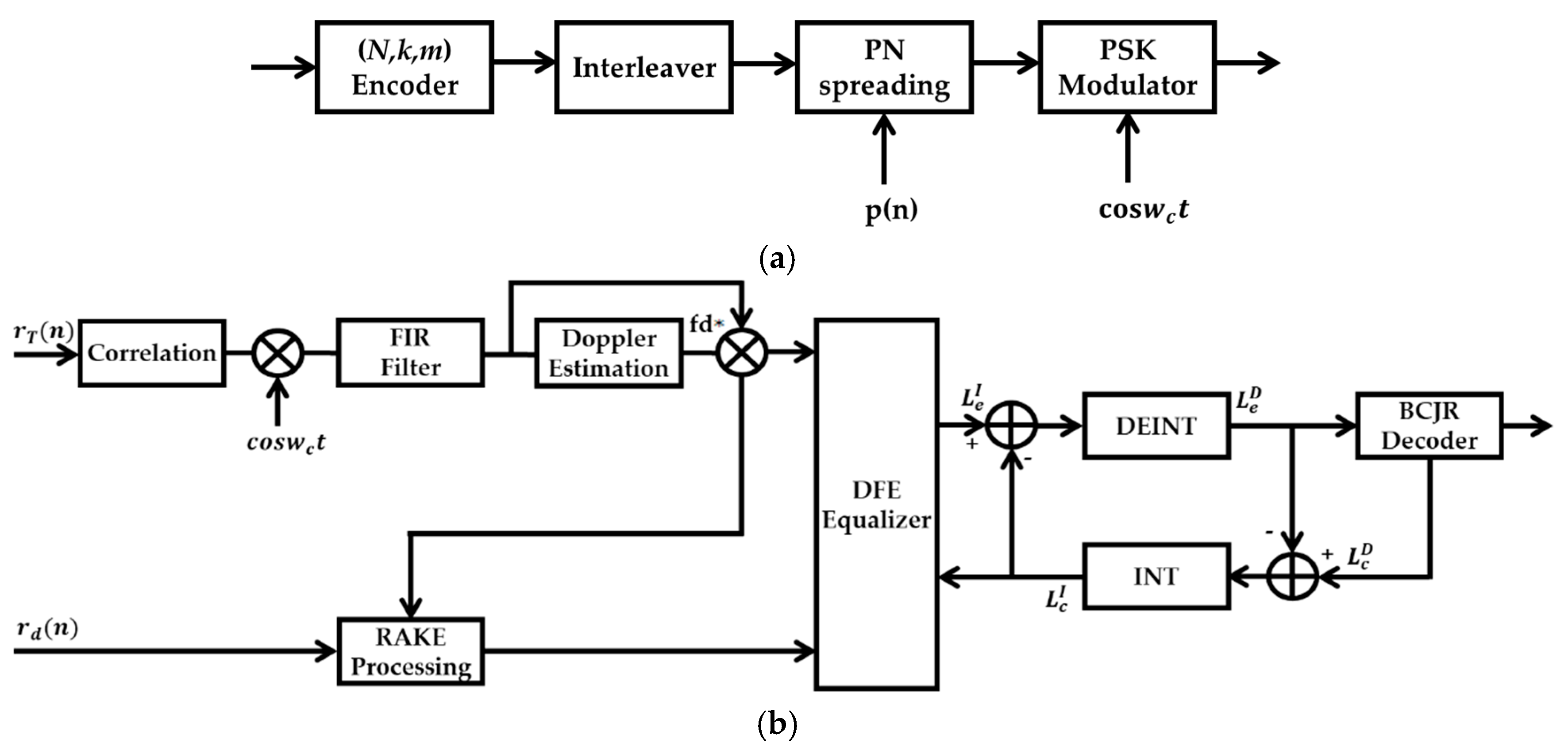
In the transmitter, as shown in
Figure 1a, the channel is coded through the (
N,
k,
m) convolutional encoder and then an interleaving process is conducted to change the burst error into the random error. To spread the spectrum, a PN spread process, in which the PN code is multiplied by a coded signal directly, is conducted, and then PN code is transmitted through modulation. In the receiver, the multiple path effect is removed through the equalizer after modulation, and then PN de-spreading is conducted to make the spread spectrum data into the original spectrum.
At the receiver side, as shown in
Figure 1b, the received signal distorted by multiple path channels is compensated by estimating channels and calculating a Doppler’s offset value using the frequency compensation algorithm and
, which is the training data portion [
13].
, which is a frequency compensation value, is transferred to the RAKE process.
, which is the data signal among the symbols received at the RAKE receiver, compensates the frequency using a frequency compensation value
and then is input to the turbo equalizer after the RAKE process. The RAKE process is as follows: The signal received at the RAKE receiver increases error due to the effect of fading, and induces interference between signals due to time delay. Thus, the RAKE receiver delays the signal arriving at the receiver through multipath as much as the chip length
of the PN code, thereby summing the calculated power of the received signal through the multipath. This process is not to sum all signals delayed as much as
, but only signals whose value is more than the threshold value from each of the branches are reflected to the output signal. The reason for this is that low-level signals whose value is lower than the threshold value can influence as an error component when producing a signal output. The threshold value is set to the second largest value after the largest value in the correlated values after de-spreading is conducted at each of the branches.
Previous work [
12] related to the successive interference cancelation (SIC) method, it required perfect channel estimation. Without perfect channel estimation, it cause performance degraded severely. Aspect to structure of RAKE receiver fields previous works, the receiver structure is very simple such as soft decision Viterbi decoder. In this paper, we employ turbo equalization technique combined with RAKE model to improve error performance. DFE as an outer codes and BCJR decoder as an inner codes, equalizer and decoder are connected through the interleaving and de-interleaving that update each other’s information repeatedly. Iteratively exchange probabilistic information between inner decoder and outer decoder makes the error rates significantly. The proposed RAKE-based turbo equalization technique improves performance by addressing a drawback of the existing RAKE-based model, as it applies the phase shift keying (PSK) technique. When the underwater channel environment is expressed with the tap delay line according to multipath, the RAKE structure selects and utilizes the optimum channel taps. The receive signal due to time delay passes through the PN de-spreading process to remove PN components using as many
taps as the number of PN code bits. A correlation is calculated by re-multiplying the frequency compensation value
at each of the taps by the PN code used for spread spectrum at the transmitter side. This operation includes the PN de-spreading procedure as well. If the PN code is not delayed for the ideal amount of time, the largest correlation value is obtained. Otherwise, a very small correlation value is obtained. A correlation is calculated and demodulation is performed through integration, and signals are decoded after combining the values using the maximum ratio combining (MRC) method through output value in each of the taps.
RAKE-Based Turbo Equalization Method with Threshold and Weighted Coefficient
The MRC method in the aforementioned RAKE-based turbo equalization technique overlaps input signals from multiple branches to obtain the optimum performance and synchronizes them before combining. The combining effect is maximized by making the contribution small for values whose correlation value is small—i.e., an extreme fading signal—and making the contribution large for values whose correlation value is large—i.e., when there is no time delay. In the MRC method, small value of correlation become self-noise among the output values in each of the taps. These self-noise values adversely affect the RAKE process. As a result, they can cause performance degradation of the receiver. This problem can be solved by giving the threshold value, which is threshold comparison based on received signal power of each of the taps. Therefore, noise is reduced from the sum of the signals by removing self-noise values which are smaller than the threshold value, by assigning the threshold value to the output value of each of the taps, thereby improving the performance. It is very important how the threshold value decide because this vale impact on performance directly. Before actual underwater experiment, we simulated transceiver model as shown in
Figure 1, based on bit error performance in accordance threshold values, we found optimal threshold value of 0.2.
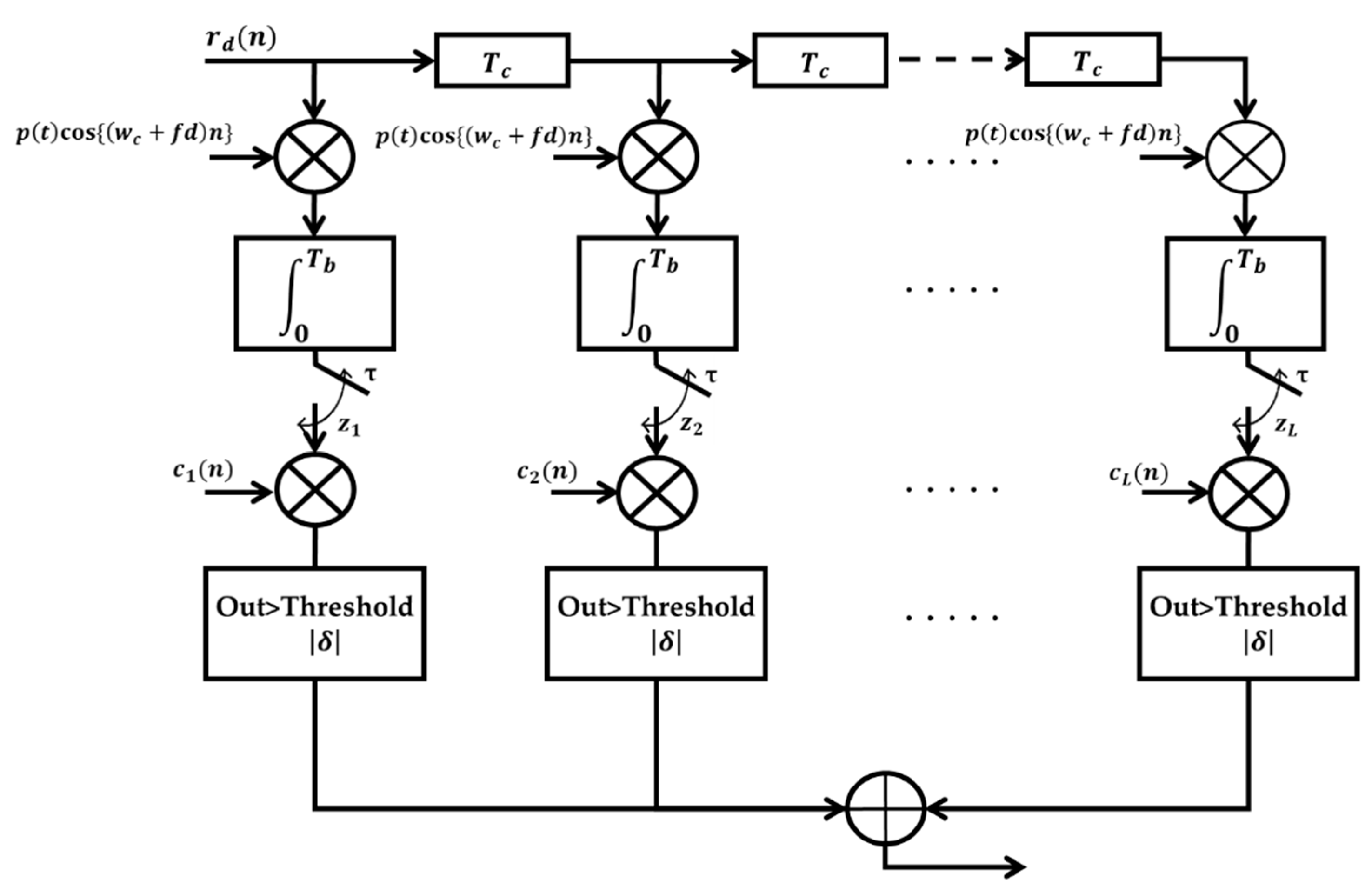
In addition, the performance of the RAKE receiver can be improved further using the weighted coefficient.
Figure 2 shows the RAKE receiver with a weighted coefficient and threshold value. The weighted coefficient plays a role in reducing self-noise at the RAKE receiver by making values whose correlation is large larger and making values whose correlation is small smaller for signals input to multiple branches in the RAKE receiver, and enlarging the combining effect in the MRC phase. The weighted coefficient is applied prior to the threshold process, and the weighted coefficient
can be expressed as follows:
refers to an output value from each of the branches and
refers to a size as much as
. After calculating the weighted coefficient
followed by multiplication with
, a correlation value output from the branch, the threshold process is carried out to combine the values.
3. Application of Multi-Sensor Covert Underwater Communication
To obtain information from each of the sensors for covert underwater communication using multiple sensors, a spread spectrum method is widely used that can obtain the information of each sensor individually from the receiver side by multiplying the codes that have orthogonal components which are different from each other in the same frequency band. Most single input single output (SISO) communication systems employ the RAKE receiver using the differential phase shift keying (DPSK) method, which is an asynchronous mode, and for multi-sensors, SIC mode [
12] is used to apply the RAKE method by eliminating interference from other sensors. This mode has drawbacks that may degrade performance if there is an error propagation effect and channel information is inaccurate. Thus, this section proposes an underwater communication structure for covert multi-sensors using an efficient decoding method and the covert underground acoustic communication technique mentioned in the previous section to overcome the above drawbacks. To do this, an efficient decoding structure is proposed.
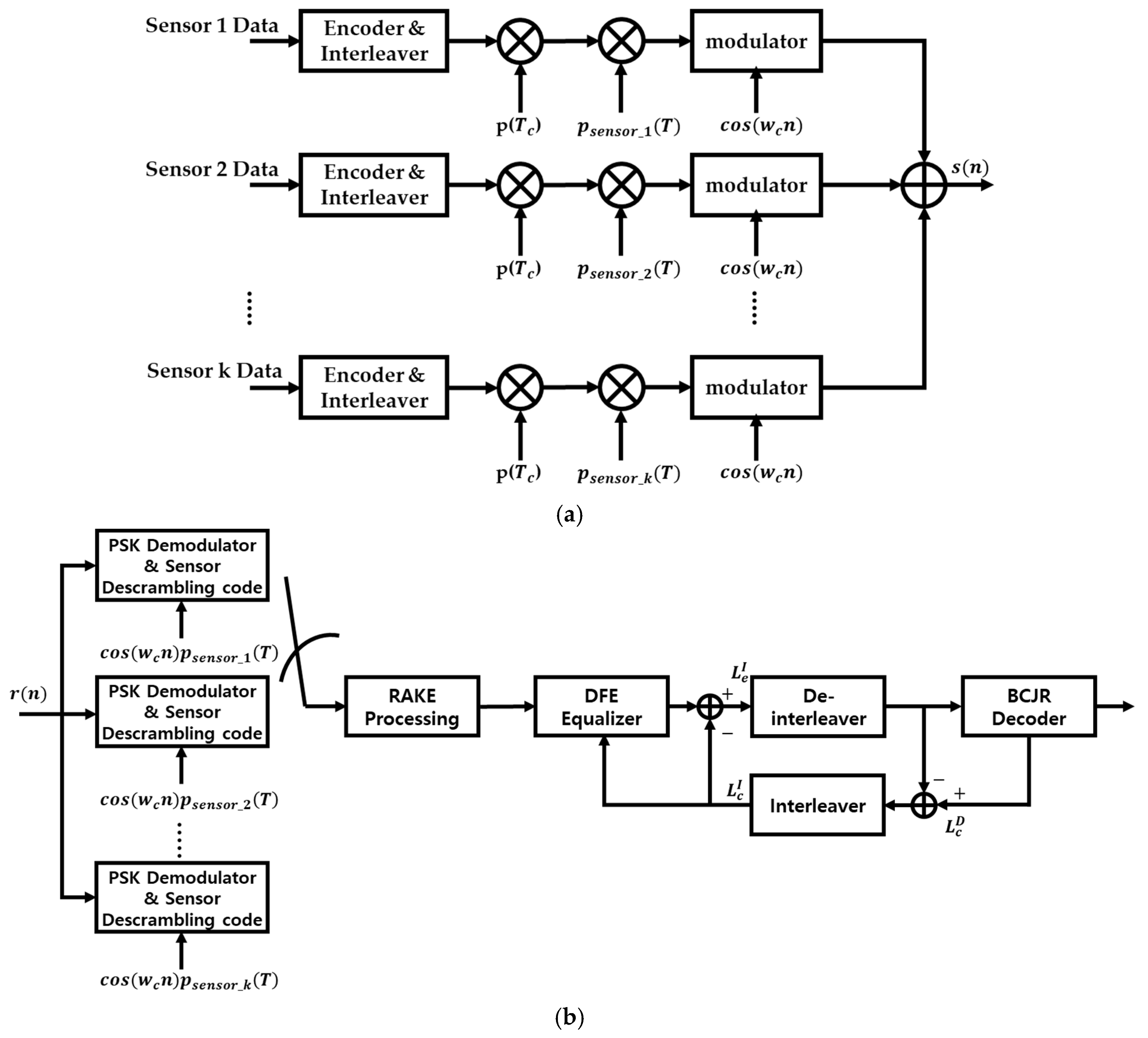
The configuration of the transmitter and receiver in the multi-sensor covert underwater communication based on the direct sequence spread spectrum is shown in
Figure 3. In transmitter model shown in
Figure 3a, data sent by the
-th sensor pass through the (2, 1, 7) convolution coding, which is a soft decision-based channel coding technology that shows excellent performance in underwater channels such as a multi-channel environment, and the interleaver in which cluster errors are changed into scatter errors. The data passing through the channel coding and interleaver are multiplied
, which is PN code for spread spectrum. Then,
, which is a sensor identification code to identify each sensor, is multiplied by the spread spectrum data, and then modulated and transmitted through the modulator.
The other sensors also transmit signals in the same manner. The final transmission signals are transmitted after summing all transmission signals from all other sensors.
Assuming that the
-th sensor’s transmission signal is
,
can be expressed as presented in Equation (2).
refers to data that is intended to be sent by the -th sensor, while and refer to lengths of PN code for spread spectrum and for sensor identification.
The
-th sensor’s transmission signal
after completing the modulation process is sent after summing transmission signals from other sensors. The final transmission signal
can be expressed with the sum of the data from all other sensors as presented in Equation (3).
refers to the total number of sensors.
At the receiver side, as shown in
Figure 3b, the transmission signal sent from the transmitter is received at the receiver after being distorted by the underwater channel characteristics. The receive signal
passes through multipath and noise is added so that it can be expressed by Equation (4) below.
refers to the total number of multipath and refers to the -th multi-path. refers to the channel response coefficient located in the -th sensor’s -th path and refers to the Gaussian noise.
The high frequency component is removed through the filter by multiplying the signal
by
for demodulation and
that is the sensor identification code, and the sensor identification code component disappears so that the
-th sensor’s data can be extracted. Equation (5) presents an equation that expresses the demodulation process to recover data of the
-th sensor from the receive signal
.
refers to the data of the signal extracted regarding the -th sensor from the receive signal, and refers to noise. After sensor identification is complete, data that require recovery pass through the RAKE process, which is a receive structure that shows excellent performance in an underwater channel environment such as multi-path. After completing the RAKE process, the receive symbols are input into the turbo equalizer. The turbo equalizer consists of DFE and BCJR encoder. The equalizer and encoder are connected via the interleaver and de-interleaver to update the other’s information iteratively, thereby improving the performance.
4. Results of Underwater Experiment
An actual underwater experiment was conducted to analyze the performance of the covert underwater acoustic communication. The underwater experiment was conducted around September 2016 at the coastal waters near Korea Maritime and Ocean University, located in Yeongdo-gu, Busan.
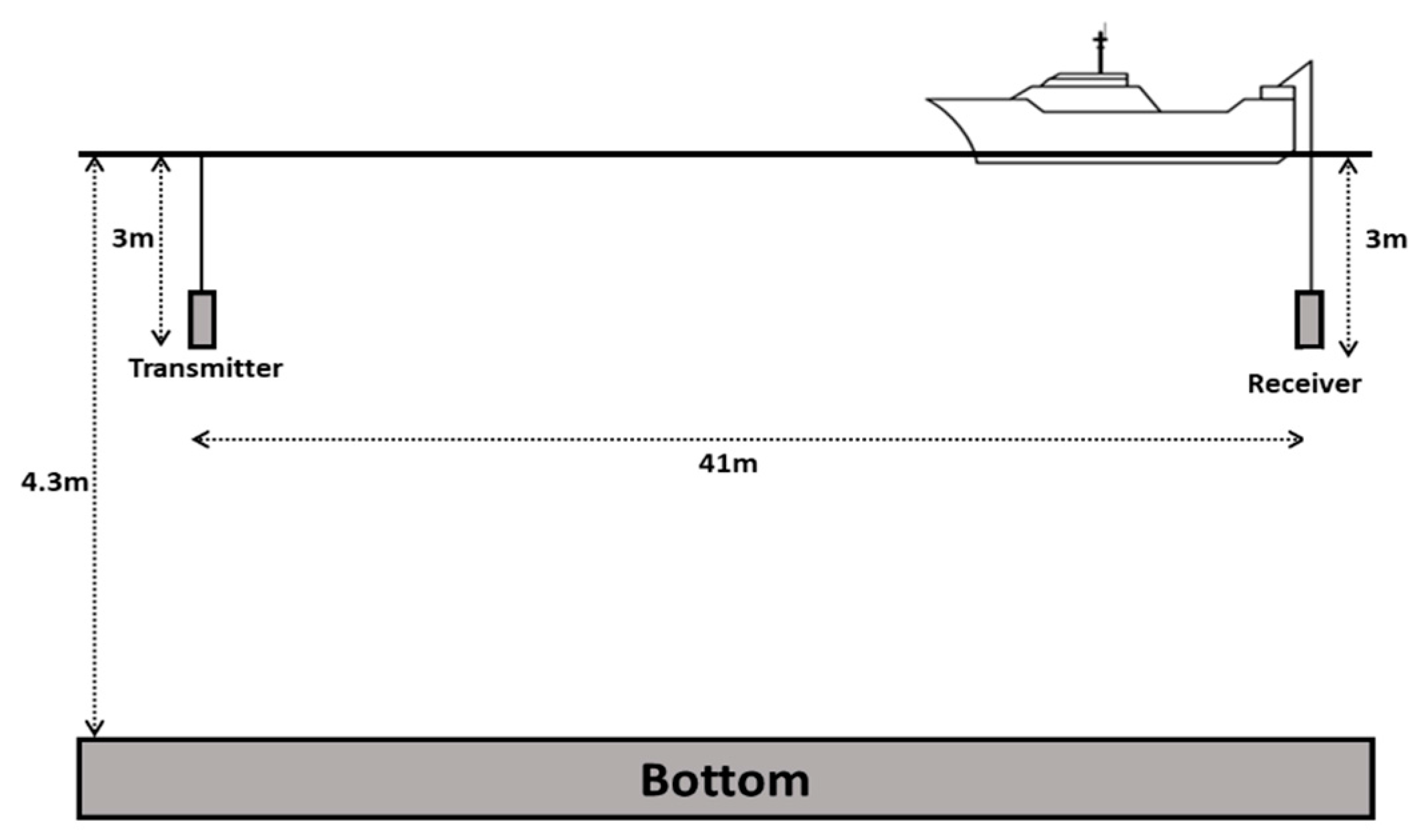
The underwater experiment environment is presented in
Table 1 and
Figure 4. The source signal was set to
bits, and bits of PN code for spread spectrum signal were 8, 16, and 32 bits. The center frequency and sampling frequency were set to 16 kHz and 192 kHz, respectively. Distance between transmitter and receiver was set to 41 m, and depth was set to 3 m from the surface of the water to conduct the underwater experiment.
4.1. Performance of Single Sensor Covert Underwater Communication
To analyze the performance of the proposed RAKE receiver, data were transmitted by varying the PN code bits . The signal is transmitted 10 times iteratively by placing a delay between data packets.
In the RAKE receiver, the threshold value and weighted coefficient proposed in this paper were applied and the number of iterations in the decoder was set to five to represent the number of errors, and packets were displayed by time. Out of 10 packets, only packets whose data were all decoded were used to compare and analyze the performance of the RAKE receiver. The performance category was divided into three cases: one in which the threshold value and the weighted coefficient were not applied to the RAKE receiver, one in which only the threshold value was applied, and one in which both the threshold value and the weighted coefficient were applied.
Table 2 presents a comparison and analysis of performance in the RAKE receiver using only packets data decoded out of 10 packets. Bit error rate listed in
Table 2 means how many errors occurred per information bits. The bit error rate is represented based on three cases: when the threshold value and the weighted coefficient were not applied to the RAKE receiver, when only the threshold value was applied, and when both the threshold value and the weighted coefficient were applied.
Through the experiment, it was found that when was 8 bits, all data were decoded in three packets out of 10; when was 16 bits, all data were decoded in four packets; and when was 32 bits, all data were decoded in five packets. With regard to packets whose data were all decoded, the performance was analyzed when the threshold value and weighted coefficient proposed in this paper were applied. When only the existing RAKE receiver was applied, errors were generated with regard to all . When the threshold value was applied, data in a majority of data packets were decoded without errors. However, even if the threshold value was applied, errors occurred in the second packet in , in the first packet in , and in the third packet in . Accordingly, the weighted coefficient was applied and all data were decoded without errors.
4.2. Multi-Sensor Covert Underwater Communication
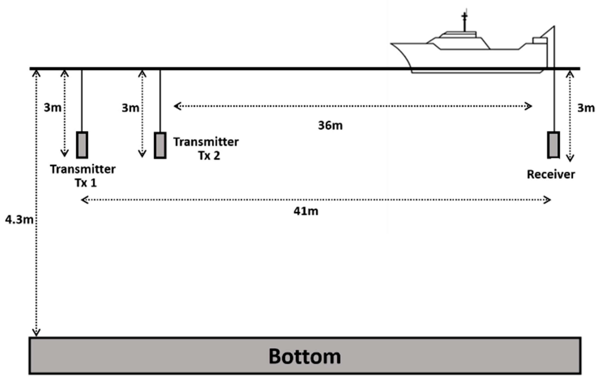
The actual underwater experiment was conducted to analyze the performance of the multi-sensor covert underwater communication. The underwater experiment was conducted in September 2016 at the coastal waters near Korea Maritime and Ocean University located in Yeongdo-gu, Busan. The experimental environment and schematic diagram are presented in
Table 3 and
Figure 5. The signal is transmitted 10 times iteratively by placing a delay between data packets.
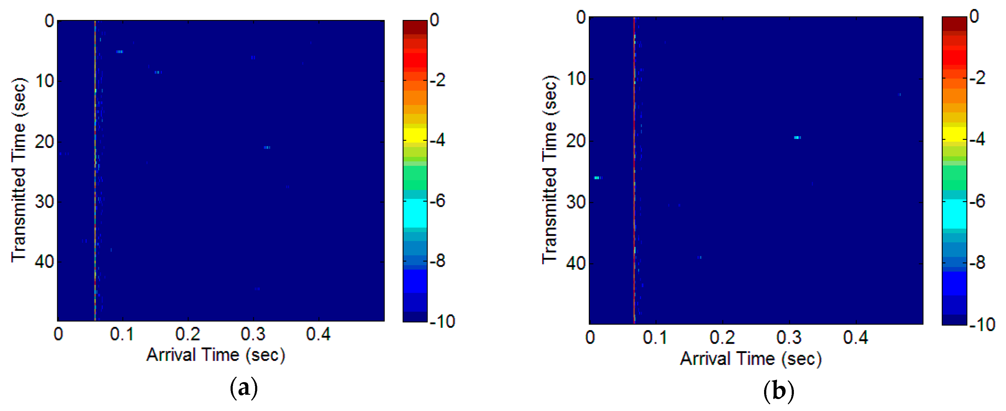
The number of actual underwater data bits was set to 500 bits, the number of transmitters was set to two, the number of sensors was two, distance to transmitter and receiver was 41 m and 36 m, distance between transmitters was 5 m, and depth of the transceiver was set to 3 m from the surface of the water. The response characteristics of each channel are shown in
Figure 6.
In the RAKE receiver, the threshold value and weighted coefficient proposed in this paper were applied, and the performance of the RAKE receiver was compared and analyzed using only packets whose data were all decoded, out of 10 packets which were performed 10 times iteratively by time.
As shown in
Table 4, as same as single user underwater communication, the result of this experiment verified that performance was improved more significantly when both the threshold value and the weighted coefficient were applied compared to when only the existing RAKE receiver was applied. When the threshold value and weighted coefficient proposed in this paper were applied, all data were decoded, with no errors.
This result indicated that the transmission and receive structure proposed through the actual underwater experiment was well-suited to the communication model for covert multiple accesses.
5. Conclusions
In recent years, a number of studies on underwater communication with the LPI characteristic have been carried out for individual and for military purposes. Previous studies on covert underwater communication have focused only on improving the transmission rate at the time varying underwater channel or increasing the transmission and receiver distance, and few studies have been conducted on transmission performance in an environment in which covertness must be emphasized. Thus, this paper proposed a transmission and receive model by applying the direct sequence spread spectrum method for LPI covert underwater communication. The RAKE receive structure was applied to the iterative decoding-based turbo equalization model to propose an efficient decoding mode, and performance was improved by applying the threshold value and weighted coefficient. Through actual underwater experiments according to by the number of PN code bits, with regard to packets whose data were all decoded, we confirmed turbo equalized RAKE model based on threshold value and weighted coefficient proposed in this paper has the best performance compared to conventional algorithms.
Furthermore, not only single sensor communication system but also multi-sensor transceiver structure was proposed based on the covert underwater communication study. As same as single user case, the results of the underwater experiments verified that performance of RAKE-based turbo equalization model proposed in this paper better than that of the conventional RAKE receive model.
In conclusion, the proposed covert underwater communication model can be effectively utilized the underwater channel environment such as multiple paths by maintaining covertness, as verified in the simulation and underwater experiments.


